 Open Access Article
Electroactive aniline tetramer–spider silks with conductive and electrochromic functionality†
Hung-Yu Wana,
Yi-Ting Chena,
Guan-Ting Lia,
Hsuan-Chen Wub,
Tsao-Cheng Huangc and
Ta-I. Yang *a
*a
aDepartment of Chemical Engineering, Chung-Yuan Christian University, Taoyuan, Taiwan. E-mail: taiyang@cycu.edu.tw; Fax: +886 3 2654199; Tel: +886 3 2654149
bDepartment of Biochemical Science and Technology, National Taiwan University, Taipei, Taiwan
cTechnical Department Plastics Division, Formosa Plastics Corporation, 814538, Kaohsiung, Taiwan
First published on 10th August 2022
Abstract
Electroactive aniline tetramer–spider silk composite fibers with high conductivity and mechanical strength were developed using a dip coating method. The fabricated spider silk composite fibers retain the high mechanical strength (0.92 GPa) and unique reversible relaxation–contraction behavior of spider dragline silks. The aniline tetramer modified on the silk surface imparted electroactive properties to the composite fibers. The color of aniline tetramer/spider silk composite fibers could be controlled by applying different pH values and voltages. Furthermore, the composite fiber's resistivity could reach 186 Ω m which can conduct electrical current to light LEDs. This study could provide a valuable guideline for developing highly-conductive electrochromic spider silks for use in E-textiles.
1. Introduction
Web-weaving spiders are well-known for their capability of producing silks with unique mechanical properties. A female orb weaving spider is able to produce up to seven different silks, including major ampullate silk, flagelliform silk, aggregate silk, minor ampupllate silk, pyriform silk, aciniform silk, and cylindriform silk, for specific purposes and they possess a range of mechanical properties.1 The most investigated spider silk is dragline silk (major ampullate silk), the main structural web silk, which is also used for the spider's lifeline, because of its unique combination of strength, extensibility, and toughness, which cannot be rivaled by most man-made fibers. For example, dragline silk has extensibility of 35% and toughness of 100 kJ kg−1 compared to extensibility of 5% and toughness of 30 kJ kg−1 for Kevlar fibers.2 The primary amino acid sequences of silk proteins combined with highly sophisticated spinning process, including acidification, ion exchange, dehydration, shearing force, and elongational flow, contribute to the outstanding mechanical properties of a dragline silk fiber.1 Furthermore, spider dragline can shrink or relax in response to the surroundings' humidity, which known as supercontraction.3 The spider dragline silk supercontracts up to 50% of its original length at high humidity and thus can build substantial stress to deliver work. The report in literature has shown that simply using wet/dry air can drive the spider dragline silk to produce work density up to 500 kJ m−3, which is 50 times higher than most biological muscles.4 The mechanism for supercontraction is not clear yet, but it could be contributed to that water molecules break the hydrogen bonds within amorphous domains of the silk proteins and enable the silks relax to their less ordered and lower energy state.3,5 In addition, spider dragline silk can also show a humidity-induced torsional deformation, which is related to the supercontraction behavior of spider dragline silk. Studies demonstrated that the dragline silk can generate a large twist deformation of more than 300° mm−1, and the torsional actuation could be tailored by tuning the surroundings' humidity.6 In addition to its unique mechanical behaviors, spider silk is a biodegradable, biocompatible, and hypo-immunogenic material so that it has great potential for biomedical and tissue engineering applications.7 For example, the spider dragline silk has been utilized as nerve guidance conduits to reconstruct peripheral nerve injuries and showed success in supporting nerve regeneration.8 In addition, the surface of the spider dragline could be modified with HfO2/ZrO2 nanoparticles or carbon nanotubes for potential bio-applications in the fields of biosensing/bioimaging or electrophysiological detection.9,10 Recently, Koop et al. revealed that the dragline silk of spiders might elicit granulomatous foreign body reaction in rat's spinal cord, yet, more researches are to be performed to elucidate the controversy.11 Furthermore, silk proteins are with highly organized secondary structures, such as β-sheets and α-helices, formed through intra- and intermolecular hydrogen bonding between their amino acid sequences. These structures are tightly-bound and behave elastic-like so that electrical dipoles could be generated reversibly, which enable silk to have piezoelectric effect to convert mechanical elastic strain energy into electrical energy. Researchers have utilized spider dragline silk to develop bio-nanogenerators for harvesting green energy, which exhibiting high energy conversion efficiency, high output voltage and current through simple mechanical or biomechanical activities.12,13 The fabricated device is biocompatible and ultra-sensitive towards physiological signal monitoring such as arterial pulse response which can be useful for potential smart biomedical applications.13Reports in literature have shown that spider silk can have various advanced applications, including artificial muscles, electro-tendons, biosensors, torsional actuators, and nanogenerators, originating from the primary and secondary structures of their constituent proteins.6,10,12–14 In this study, we further explored the feasibility of spider silks for applications in highly demanding wearable electronic textiles (E-textiles).15 Spider silks have significant potential to become a sustainable alternative to fossil-fuels-based materials not only because their remarkable mechanical properties and biocompatibility, but also their sustainability and biodegradability to meet the requirement of circular economy and green chemistry for fabricating E-textiles.16
Polyaniline has great potentials for applications in electrochromic systems, anticorrosion coatings, electronic sensors, and biomedical fields because of their high intrinsic electrical conductivity, biocompatibility, and controllable oxidation/protonation states.17,18 Several studies have reported that polyaniline could be utilized to increase the electrical conductivity of the spider silk.19,20 However, the poor solubility in common solvents makes polyaniline difficult to process.21 In this study, we utilized the aniline tetramer, which is the smallest aniline oligomer that can have the same oxidation-reduction/doping-undoping structures as polyaniline,22 to develop electroactive spider silks with appreciable electrical conductivity for potential applications in E-textiles. We demonstrated the feasibility, for the first time, that a simple dip coating method can modify the surface of spider dragline silk with aniline tetramer to impart the conductivity and electroactivity to the composite fibers. The developed spider silk composite fibers not only remain the high mechanical strength (0.92 GPa), but also the unique reversible relaxation–contraction behavior of spider dragline silks. Furthermore, the color of the composite fibers could be controlled by the applied voltage or adjusting their pH values. The electrical conductivity of the spider dragline silk could be improved with aniline tetramer and thus allow the composite fibers to conduct electrical current to light LEDs.
2. Experimental
2.1. Materials
N-Phenyl-p-phenylenediamine (98%, Alfa Aesar), ferric chloride hexahydrate (99%, Showa), and ethyl alcohol (Aldrich ACS grade, 95.0%) were used as received without further purification. The indium tin oxide (ITO) electrode (surface resistivity 7–10 Ω sq−1) was purchased from GemTech Optoelectronics Corp. Ltd in Taiwan.2.2. Collection of dragline silk fibers
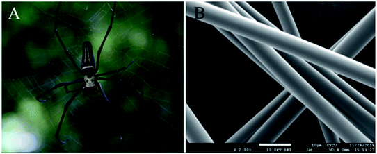
The dragline silks from Nephila pilipes were chosen to fabricate the electroactive composite fibers. The adult female Nephila pilipes with a unique body signature, black-to-yellow vertical stripes on the dorsum, was caught at Wufengchi Waterfall recreation area in Taiwan (Fig. 1(a)). Species validation was performed under a stereo-microscope, based on morphology and taxonomic signatures. For silk collection, the tailored-made motorized roller was fabricated as a silk collector. The reeling speed of the silk roller was adjustable (ranging from 1 m min−1 to 20 m min−1) by tuning the control knob and the speed was stably-maintained under the regulation by the gear set equipped to the roller. Additionally, a tachometer was utilized to calibrate and validate the actual collection speed of the roller in operation. The major ampullate dragline silks were force-pulled in air from its spinneret at a speed close to 3 m min−1. The surface of the dragline silk is smooth without any distinct feature as shown in Fig. 1(b).2.3. Aniline tetramer synthesis
Aniline tetramer was prepared using the procedure reported in literature.23,24 N-Phenyl-p-phenylenediamine (2 g) was dissolved in 200 mL of 1 N hydrochloric acid (HCl) and kept its temperature at 0 °C. Subsequently, a solution of ferric chloride hexahydrate (4.9 g in 30 mL of 1 N HCl) was added into the prepared N-phenyl-p-phenylenediamine solution. The resulting mixed solution was allowed to react for 4 hours at 0 °C. The greenish aniline tetramer precipitate (emeraldine salt state, ES) was collected using centrifugation and washed with 1 N ammonium hydroxide solution to obtain bluish emeraldine base (EB) of aniline tetramer.2.4. Preparation of electroactive aniline tetramer silk fibers
The dragline silks collect from Nephila pilipes were mounted on the frame and then immerse in aniline tetramer solution for two hours. The resulting aniline tetramer modified silks were dried in 60 °C oven after the dip-coating process shown in Scheme 1. The aniline tetramer solution was prepared by dissolving required amount of aniline tetramer (EB state) in 95% ethyl alcohol. The utilized concentrations are 0.01%, 0.05%, 0.1%, 1%, or 10%.2.5. Characterization
FTIR spectrometer (JASCO FTIR-4100) was utilized to characterize the chemical structure of the synthesized aniline tetramer and the resulting composite silk fibers. The samples for FTIR testing were embedded in the potassium bromide pellet and measured at room temperature. The morphology and size of spider dragline fibers were observed by using a scanning electron microscopy equipped with energy dispersive X-ray (EDX) analyzer (SEM, Hitachi S-2300). The samples were platinum-sputtered first and then observed in the secondary electron imaging mode at 10 keV. The mass spectrum of aniline tetramer was obtained using an electrospray ionisation mass spectrometer (ESI-MS, Bruker Compact ESI QTOF mass spectrometer). The breaking strength and extensibility of the aniline tetramer/spider dragline silk composite fibers were tested by a Compact Tabletop Testing Machine (EZ-X, Shimadzu Corporation, Tokyo, Japan). The composite silk threads were gently aligned and taped on paper cardboard frames separately, with an effective gauge length of 5 cm. To obtain the silk diameter, a Nikon Eclipse E600 microscope (Nikon Corporation, Tokyo, Japan) was utilized to evaluate the diameter of silk samples. Subsequently, the silk-carrying cardboard frame was mounted on the tensile tester. The side support of the frame was gently cut away by dissection scissors allowing direct force transmission through the silk fiber. The tensile measurement was carried out with a tensile speed of 0.5 mm min−1 and an environmental control of 28 °C and 40–60% RH. The final stress of the silk threads was calculated by normalizing the force to the total cross-section area of silk threads. The crystalline structure of the electroactive composite fibers were studied using X-ray diffraction. Their X-ray diffraction patterns were obtained at TLS 01C2 beamline (wavelength of 0.1 nm) located in National Synchrotron Radiation Research Center, Hsinchu, Taiwan. The composite spider silks were swathed on a steel frame and placed at a distance of 350 mm from the detector. The data collection time was five minutes each sample and then processed using GSAS software. For electrical conductivity measurement, the single composite fiber with a length of 2 cm was connected in a two-terminal conductivity configuration without any stress present within the fiber using a silver conductive paste. Subsequently, the current–voltage (I–V) measurements were performed at ambient pressure and temperature of 20 °C using a SourceMeter instrument (Keithley 2614B, Tektronix, USA). The resistance (R) of the sample could be deduced from the resulting I–V plot, and thus the resistivity (ρ) can be calculated according to eqn (1).| ρ = R × A/L | (1) |
Statistical analysis (ANOVA) was performed on the data (including tensile properties and electrical resistivity) for significance test.
2.6. Electrochemical cyclic voltammetry (CV) measurement
The electroactive property of the developed aniline tetramer/silk fibers was studied using CV measurement. For preparing a working electrode, a conductive indium tin oxide (ITO) glass was exposed to ethyl alcohol vapor first so that a thin layer of ethyl alcohol formed on the ITO surface. Subsequently, the composite fibers, a bundle of fibers containing 150 single threads with 6 cm in length, were immediately placed on it and dried in 60 °C oven. The ethyl alcohol on the ITO surface ensured a good contact between fibers and ITO surface for reliable CV measurement. The CV measurement was performed in 1.0 M sulfuric acid solution. The testing potentials ranged from −0.2 to 1.0 V vs. Ag/AgCl, at a scan rate of 50 mV s−1 using silver/silver chloride reference electrode and platinum counter electrode. In addition, the electrical conductivity of the virgin dragline silks is low so that its thin film was cast on the ITO electrode to increase the current response as testing potential applied. In preparation of virgin dragline silk thin films, 20 mg of dragline silk was dissolved in 1 mL of hexafluoroisopropanol and then the resulting solution was air-dried on the ITO electrode to form a silk thin film with an area of 4 cm2 and 40 μm in thickness.2.7. Ultraviolet-visible (UV-Vis) analysis
UV-Vis analysis of the aniline tetramer was performed with JASCO V-750 UV-Vis spectrophotometer (JASCO International Co. Ltd., Tokyo, Japan). The as-synthesized emeraldine base (EB) state of aniline tetramer was dissolved in N-methyl-2-pyrrolidone for measurement at room temperature. In addition, UV-Vis spectroscopy was also utilized to quantitatively determine the amount of aniline tetramer modified on the surface of dragline silk. Firstly, the specific amount of electroactive fiber was immersed in 95% ethyl alcohol with assisted with sonication to strip off all the aniline tetramer attached on the surface of the dragline silk. Subsequently, the resulting aniline tetramer solution was analysed with UV-Vis spectroscopy by measuring the absorbance at 588 nm wavelength and the aniline tetramer concentration could be calculated according to the calibration curve (eqn (2) in Fig. S1†). Therefore, the amount of aniline tetramer on the silk surface could be obtained.2.8. The dragline silks' humidity-driven behaviour
The behavior of humidity-driven reversible relaxation–contraction response of the composite fibers was investigated. The two ends of the prepared composite dragline silk bundle were fixed in a frame and a plastic ring (load) was hung on the middle of the bundle. For the “wet state”, the bundle was saturated with water at room temperature, leading to relaxation of silk and thus the position of the hung load was lowered. In the contrast, the “dry state” of the silk bundle was reached by blowing the 60 °C dry air so that the water within the silk was removed, causing the contraction of the silk and thus the hung load was elevated.3. Results and discussion
3.1. Characterization of synthesized aniline tetramer
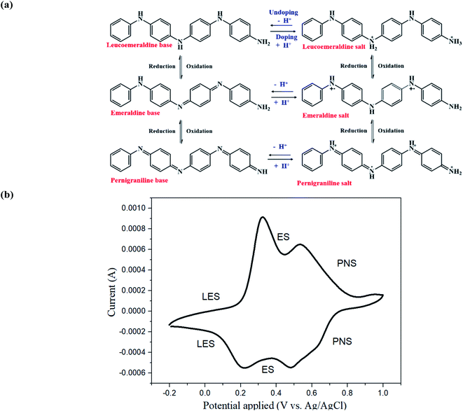
Aniline tetramer has three specific oxidation-reduction states and their related doping/undoping states: fully reduced state (leucoemeraldine salt, LES and leucoemeraldine base, LEB), the half oxidized state (emeraldine salt, ES and emeraldine base, EB) and the fully oxidized state (pernigraniline salt, PNS and pernigraniline base, PNB) (Fig. 2(a)25,26). Consequently, it possess unique electrical, chemical, and optical properties and has numerous advanced applications including bioseparating materials, electrochemical sensors, supercapacitors, and mediators for enhancing differentiation of neural stem cells or facilitating the photothermal effect for cancer therapy.21,27–30The as-prepared aniline tetramer in this study was in proton-doping state because of synthesizing in HCl solution. Subsequently, it was washed with ammonium hydroxide solution to become un-doping state for spider silk modification. The synthesized aniline tetramer was characterized by a mass spectrometer. The results shows [M + H]+ ions at m/z = 365.2, which indicates that it is in its most stable EB state C24H20N4 = 364.3 (Fig. S2†). The chemical structure synthesized aniline tetramer was analyzed by FTIR (Fig. S3†). The peak of 1504 cm−1 and 1594 cm−1 could be assigned to benzenoid and quinoid rings stretching vibrations, respectively. There three peaks at 1309, 1161 and 851 cm−1 are from the C–N stretching vibration of a secondary aromatic amine, the aromatic C–H in-plane deformation, and the C–H out-of-plane deformation of 1,4-aromatic substituted benzene rings, respectively.31
UV-Vis spectroscopy was utilized to investigate the UV-visible absorption behavior of the synthesized aniline tetramer. The as-synthesized emeraldine base (EB) of aniline tetramer exhibited two distinct absorption peaks (λmax) at 319 nm and 588 nm, which could contribute to the π–π* transition in the benzenoid ring and exciton absorption in the quinoid rings, respectively (Fig. S4†).32,33 The cyclic voltammetry measurement could confirm the electroactive behavior of aniline tetramer, which showing two oxidation peaks at 0.32 V and 0.54 V (Fig. 2(b)). The first oxidation peak at 0.32 V and the second oxidation peak at 0.54 V contribute to the transition from fully reduced LES state to half oxidized ES state and half oxidized ES state to fully oxidized PNS state, respectively. These results shows electroactive aniline tetramer have been successfully synthesized.
3.2. Electroactive spider silks
Typical orb-weaver draglines are made of major ampullate spidroin protein 1 and 2 (MaSp1 and MaSp2), which containing mainly a high content of glycine (G) (34.7–42.2%), alanine (A) (17.6–27.5%), and proline (1.7–15.7%) amino acid residues,34 and their poly(A) and poly(GA) domains forms crystalline β-sheets, leading to the dragline silk as a semi-crystalline polymer.2 Accordingly, the dragline silk of Nephila pilipes utilized in study is in semi-transparent white color as shown in Fig. 3(a). In addition, a water drop can sit on the pristine dragline silk bundle without penetration, and the water contact angle is larger than 90° (Fig. 3(a)), indicating the hydrophobic behavior. The fact that dragline silks repel the high surface energy water is due to the hydrophobic lipid coating on the silk and the hydrophobic air surroundings.35–37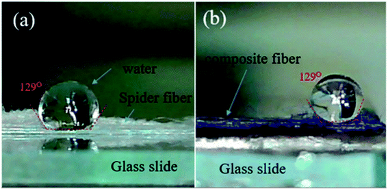 | ||
| Fig. 3 (a) Image of virgin Nephila pilipes dragline silk. (b) Image of aniline tetramer-coated Nephila pilipes dragline silk. | ||
The synthesized aniline tetramer could coat on the surface of the dragline silk after dip-coating procedure as evidenced by the pronounced peaks of aniline tetramer appear in the composite silk's FTIR spectrum (Fig. S5†). In addition, the color of the silk can be utilized to justify if the aniline tetramer coated on the silk surface. Fig. 3(b) shows the optical image of the aniline tetramer/silk composite fibers with the blueish color, indicating that the dragline surface is covered with EB aniline tetramer, compared to pristine silk in semi-transparent white color. The composite fibers still behaves hydrophobic as the water contact angle is larger than 90°.
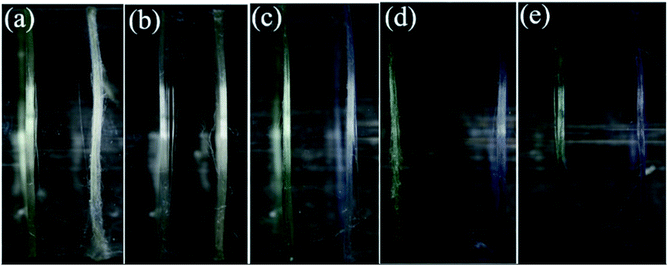
The aniline tetramer could have different colors, which depends on its energy gap resulting from the insertion/de-insertion of dopant ions.38 The prepared aniline tetramer for dip-coating procedure in this study was in emeraldine base (EB) state (deprotonated emeraldine) so that the color of the resulting composite silk is blueish and its color became greenish when protonating with HCl solution (protonated emeraldine, emeraldine salt ES state).39 The aniline tetramer concentration for dip-coating procedure significantly affected its amount modified on the silk's surface as shown in Fig. 4. Apparently, there are not much aniline tetramer attached on the silk surface as using 0.01% and 0.05% aniline tetramer solution for coating process since it seems that the silk still exhibits colorless as shown in Fig. 4(a) and (b). Investigating their SEM images confirms that there are only few aniline tetramer particles deposited on the silk surface, as shown in Fig. 5(a) and (b), similar to the smooth without any distinct feature of pristine silks (Fig. 1(b)). More aniline tetramer particles attached on the silk surface as dip-coating concentration further increased to 0.1% (Fig. 5(c)). The silk surface could be completely covered by the aniline tetramer as the dip-coating concentration reached 1% (Fig. 5(d)). However, higher solution concentration of 10% not only allows the individual silk fiber covered with aniline tetramer, but also caused two silk fibers to connect together (Fig. 5(e)). In addition, some silk fibers' surface appears smooth, indicating no aniline tetramer on the silk surface (Fig. 5(f)). This result is due to that there is no strong bonding between the aniline tetramer layer and the silk surface. Therefore, the thick aniline tetramer layer can easily detach from the silk surface under disturbance such as preparation for SEM investigation. In contrast, Fig. S6† shows that the composite fibers prepared by 1% aniline tetramer did not have any significant coating delamination even after stirring in water at speed of 1000 rpm for 7 days. In addition, surface-treatment method also performed to figure out whether the coating layer delamination issue could be improved. It is generally accepted that there is a lipid coating on the surface of silk fibers35–37 and it can be stripped by organic solvents.36 Therefore, dragline silks were washed in hexane for ten minutes to remove the lipid layer before dip-coating with aniline tetramer. Fig. S7(a)† shows the surface of the dragline silk is smooth without any distinct feature after hexane treatment. In contrast, aniline tetramer particles attached on the silk surface can be observed after subsequent 0.1% dip-coating procedure (Fig. S7(c)†), and the silk surface could be completely covered by the aniline tetramer as the dip-coating concentration reached 1% (Fig. S7(d)†). Increasing dip-coating concentration to 10% can also obtain silks coated with aniline tetramer (Fig. S7(e)†), but coating delamination phenomenon still appeared (Fig. S7(f)†). These results suggest that using hexane to remove the lipid layer on the silk surface did not improve the poor adhesion between the aniline tetramer coating and the silk surface. In summary, higher dip-coating concentration led to more aniline tetramer coated on the silk surface. However, excessive aniline tetramer could have adverse effect on the coating layer as found in the result of 10% aniline tetramer dip-coated composite fibers. The amount of aniline tetramer on the silk surface was evaluated using UV-Vis analysis and the result was summarized in Table S1.†
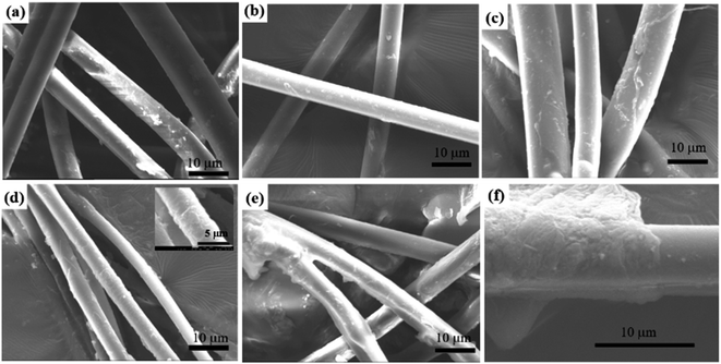 | ||
| Fig. 5 SEM images of spider dragline silks modified with various concentration of aniline tetramer solution. (a) 0.01%; (b) 0.05%; (c) 0.1%; (d) 1%; (e) 10%; (f) 10%. | ||
EDX analysis was also utilized to obtain the composition and the quantity of elements in the composite silks. The results were summarized in Table S2,† indicating only elements of C, O, and N in virgin silks and the atomic percent of these elements do not change significantly after aniline tetramer modification process (ANOVA analysis p > 0.05). These results are due to similar atomic composition of aniline tetramer coating and spider silk fibers, as well as element quantity provided by the EDX analysis was not only from the aniline tetramer layer, but also from the dragline silk.
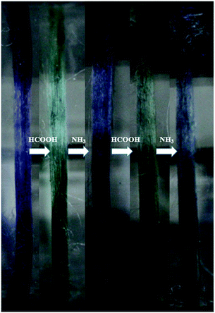
Furthermore, aniline tetramer, which having proton doping/un-doping capacity, could enable the spider silk to become pH responsive color changing fibers. The color of aniline tetramer in EB deprotonated and ES protonated state is blueish and greenish, respectively. The proton doping/un-doping procedure could be done not only by immersing the composite fibers in acidic/basic solutions, but also by exposing them in acidic/basic vapors. Fig. 6 shows the as-prepared aniline tetramer/dragline silk composite fibers could reversibly change their colors from blueish to greenish and then back to blueish simply by exposing to formic acid (HCOOH) and ammonia (NH3) vapors, respectively.
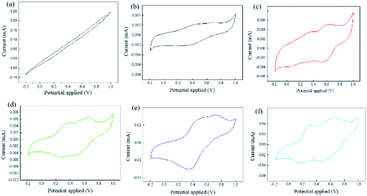
In addition, the aniline tetramer enables the spider silk to be electroactive, which confirmed by the cyclic voltammetry measurement as shown in Fig. 7. The virgin dragline silk did not exhibit any redox transition as the testing potentials ranged from −0.2 to 1.0 V. In contrast, there are distinct redox peaks present in the cyclic voltammetry test for all silk modified with aniline tetramer. The first pair of redox peaks close to 0.34 V oxidation peak was due to the aniline tetramer's transition from its fully reduced LES state to half oxidized ES state. The second pair of redox peaks with the oxidation potential close to 0.64 V contributes to the transition from its half oxidized ES state to fully oxidized PNS state. The pure aniline tetramer only need 0.54 V to switch its state from ES to PNS. However, the aniline tetramer/dragline silks required higher potentials due to their lower electrical conductivity compared to pure aniline tetramer. Furthermore, the redox current increased as increasing the added amount of aniline tetramer. These results confirm that aniline tetramer can impart electroactivity to the spider dragline silks. Moreover, the aniline tetramer/dragline silks could reversibly switch their colors by applying electrical voltages, which resulting from the electrochromic property of aniline tetramer. Fig. 8 demonstrates that the composite silk fibers showed bluish and greenish as the applied voltage was 0.9 V and 0.1 V, which relating to the aniline tetramer at PNS and LES state, respectively. These electrochromic behaviors are similar to the related polyaniline studies reported in literature since the aniline tetramer is the smallest oligomer unit that can fully represent the structure of polyaniline.40–44
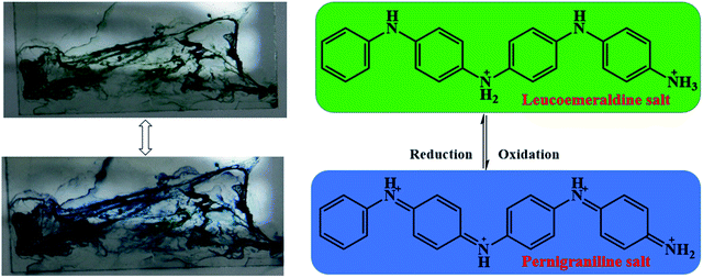 | ||
| Fig. 8 Effect of applied voltage on the color of aniline tetramer/silk fibers (top: 0.1 V; bottom: 0.9 V). (dragline silk is modified with 1% of aniline tetramer solution). | ||
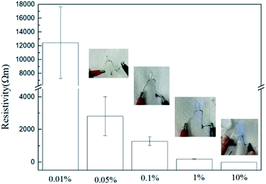
Aniline tetramer in the emeraldine base (EB) state can be acid doped/protonated to form the conducting emeraldine salt (ES) state,39 which can lower the electrical resistivity of the spider dragline silk. The electrical resistivity of the dragline silks modified with different amount of aniline tetramer is shown in Fig. 9. The silk composites exhibited high electrical resistivity at low incorporated aniline tetramer amount. However, the electrical resistivity significantly lowered to 186 and 2 Ω m as utilizing 1% and 10% aniline tetramer solution for dip-coating procedure, respectively (statistical significance: ****P < 0.0001). The resistivity is low enough so that it can conduct electrical current to light up LEDs, as demonstrated in Fig. 9.
3.3. Mechanical properties of electroactive spider silks
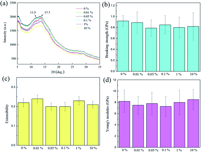
The dragline silk of orb-weaving spiders is known for its unique combination of strength, and extensibility, which cannot rivaled by most man-made fibers. Generally, its breaking strength ranges from 0.8 to 1.5 GPa and extensibility close to 30%.45–48 The dragline silks from Nephila pilipes utilized in this study have Young's modulus of 8.2 GPa, extensibility of 0.22, and breaking strength of 0.92 GPa (Fig. 10). Spider silk can be considered as a semicrystalline polymer, which its β-sheet crystalline region provides the strength, while the amorphous regions contributes to the elasticity of the silk.49 The X-ray diffraction results show that there are two distinct 2θ peaks at 11.9° and 13.3°, which are the β-sheet crystalline d-spacings of 4.8 and 4.3 angstroms,50 respectively, present for the virgin dragline silk. These two peaks do not shift or disappear after the aniline tetramer coating procedure, indicating the original β-sheet crystalline did not significantly be affected. Furthermore, the mechanical testing for the aniline tetramer-modified silks also reveal that their Young's modulus, extensibility, and breaking strength are similar to the un-modified one, as shown in Fig. 10. These results indicate that aniline tetramer do not penetrate the silk's microstructure and thus alter the spatial arrangement of the chain (secondary structure) so that the mechanical properties do not significantly be affected by the aniline tetramer modification process. on breaking strength (P > 0.05), extensibility (P > 0.05), and Young's modulus (P > 0.05).In addition to the mechanical properties, the aniline tetramer coatings neither interfere with the dragline silk's reversible relaxation–contraction response to humidity. “It is well-known that there are many hydrogen bonds within the secondary structure of the fibroins in virgin dragline silk. Water can penetrate silk and thus break hydrogen bonds between fibroins, thereby allowing the fibroins to re-arrange to lower energy levels and result in silk's irreversible supercontraction.51 Removing water from the post-supercontraction silk allows the reformation of hydrogen bonding, which stiffening and contracting the dragline silk. When wetting the silk again, water can break the reformed hydrogen bonds, thus relaxing the silk and lowering its stiffness. The post-supercontraction silk's relaxation–contraction response to wetting and drying is highly reversible and has led to the development of humidity-driven actuators.6,52,53 Our prepared aniline tetramer/silk threads also exhibited such humidity-driven reversible phenomenon as shown in Fig. 11. The plastic ring (load) hung on the middle of the prepared composite bundle was in the relaxation state as saturated with water (wet state). Subsequently, the water within the silk was removed (dry state), which causing the reformation of hydrogen bonding and thus silk contracted so that the hung load was elevated. Again, the hydrogen bonds could be broken by water (wet state), leading to relaxation of silk and thus the position of the load lowered. This contraction and relaxation behavior is highly reversible and did not be affected by the aniline tetramer on the surface of the silk.
4. Conclusions
We have shown the success of developing electroactive spider silk fibers with outstanding mechanical properties. Aniline tetramer was synthesized and subsequently incorporated to the surface of spider dragline silk fibers by using dip-coating technique. The aniline tetramer can impart electroactivity to the spider dragline silks and thus could reversibly switch their colors by applying electrical voltage. In addition to the electroactive/electrochromic behaviors, the developed composite silk fibers also can conduct electrical current to light the LED. Furthermore, the aniline tetramer can also enable the silk fibers to have proton doping/un-doping capacity so that they become pH responsive color changing fibers. For the mechanical properties, the resulting composite fibers have extensibility close to 25%, and breaking strength of 0.9 GPa, which cannot rivaled by most man-made fibers. Importantly, the spider dragline silk's unique relaxation–contraction response to humidity did not be affected by the aniline tetramer modification process. They could cyclically shrink and relax at low and high humidity surroundings, respectively. Thus, the aniline tetramer/spider dragline silk composite fibers developed in this study could provide a new avenue to fabricate multi-functional fibers with outstanding mechanical properties for applications in E-textiles.Conflicts of interest
There are no conflicts to declare.Acknowledgements
This material is based on work supported by Research Center for Circular Economy in Chung-Yuan Christian University and the Ministry of Science and Technology, Taiwan, R. O. C. (grant nos MOST 109-2221-E-033-038 and MOST 110-2221-E-033-007).References
- L. Eisoldt, A. Smith and T. Scheibel, Mater. Today, 2011, 14, 80–86 CrossRef CAS.
- O. Tokareva, M. Jacobsen, M. Buehler, J. Wong and D. L. Kaplan, Acta Biomater., 2014, 10, 1612–1626 CrossRef CAS PubMed.
- T. Giesa, R. Schuetz, P. Fratzl, M. J. Buehler and A. Masic, ACS Nano, 2017, 11, 9750–9758 CrossRef CAS PubMed.
- I. Agnarsson, A. Dhinojwala, V. Sahni and T. A. Blackledge, J. Exp. Biol., 2009, 212, 1990 CrossRef PubMed.
- T. A. Blackledge, C. Boutry, S.-C. Wong, A. Baji, A. Dhinojwala, V. Sahni and I. Agnarsson, J. Exp. Biol., 2009, 212, 1981 CrossRef PubMed.
- D. Liu, A. Tarakanova, C. C. Hsu, M. Yu, S. Zheng, L. Yu, J. Liu, Y. He, D. J. Dunstan and M. J. Buehler, Sci. Adv., 2019, 5, eaau9183 CrossRef CAS PubMed.
- S. Salehi, K. Koeck and T. Scheibel, Molecules, 2020, 25, 737 CrossRef CAS PubMed.
- A. Naghilou, L. Pöttschacher, F. Millesi, A. Mann, P. Supper, L. Semmler, T. Weiss, E. H. G. Backus and C. Radtke, Mater. Sci. Eng., C, 2020, 116, 111219 CrossRef CAS PubMed.
- A. Kiseleva, G. Kiselev, V. Kessler, G. Seisenbaeva, D. Gets, V. Rumyantseva, T. Lyalina, A. Fakhardo, P. Krivoshapkin and E. Krivoshapkina, ACS Appl. Mater. Interfaces, 2019, 11, 22962–22972 CrossRef CAS PubMed.
- J. Hou, Y. Xie, A. Ji, A. Cao, Y. Fang and E. Shi, ACS Appl. Mater. Interfaces, 2018, 10, 6793–6798 CrossRef CAS PubMed.
- F. Koop, S. Strauß, C.-T. Peck, T. Aper, M. Wilhelmi, C. Hartmann, J. Hegermann, J. Schipke, P. M. Vogt and V. Bucan, PLoS One, 2022, 17, e0264486 CrossRef CAS PubMed.
- C.-T. Pan, C.-K. Yen, M.-C. Hsieh, S.-Y. Wang, C.-H. Chien, J. C.-C. Huang, L. Lin, Y.-L. Shiue and S.-W. Kuo, ACS Appl. Energy Mater., 2018, 1, 5627–5635 CAS.
- S. K. Karan, S. Maiti, O. Kwon, S. Paria, A. Maitra, S. K. Si, Y. Kim, J. K. Kim and B. B. Khatua, Nano Energy, 2018, 49, 655–666 CrossRef CAS.
- L. Pan, F. Wang, Y. Cheng, W. R. Leow, Y.-W. Zhang, M. Wang, P. Cai, B. Ji, D. Li and X. Chen, Nat. Commun., 2020, 11, 1332 CrossRef CAS PubMed.
- E. Ismar, S. Kurşun Bahadir, F. Kalaoglu and V. Koncar, Global Challenges, 2020, 4, 1900092 CrossRef PubMed.
- T.-L. Chen, H. Kim, S.-Y. Pan, P.-C. Tseng, Y.-P. Lin and P.-C. Chiang, Sci. Total Environ., 2020, 716, 136998 CrossRef CAS PubMed.
- C. Bavatharani, E. Muthusankar, S. M. Wabaidur, Z. A. Alothman, K. M. Alsheetan, M. m. Al-Anazy and D. Ragupathy, Synth. Met., 2021, 271, 116609 CrossRef CAS.
- E. N. Zare, P. Makvandi, B. Ashtari, F. Rossi, A. Motahari and G. Perale, J. Med. Chem., 2020, 63, 1–22 CrossRef CAS PubMed.
- O. Karthaus and K. Miyaura, Mol. Cryst. Liq. Cryst., 2017, 654, 263–267 CrossRef CAS.
- H. Goto, R. Kikuchi and A. Wang, Fibers, 2016, 4, 12 CrossRef.
- E. Yagudaeva, A. Vikhrov, Y. Malakhova, Y. Iskandyarova, M. Firsova, A. Prostyakova, A. Korovin, S. Malakhov, A. Nichugovskiy, V. Zubov and D. Kapustin, Synth. Met., 2021, 274, 116712 CrossRef CAS.
- Y. Wang, H. D. Tran, L. Liao, X. Duan and R. B. Kaner, J. Am. Chem. Soc., 2010, 132, 10365–10373 CrossRef CAS PubMed.
- S.-C. Yang, C.-Y. Chen, H.-Y. Wan, S.-Y. Huang and T.-I. Yang, Polymers, 2019, 11, 1430 CrossRef CAS PubMed.
- W. J. Zhang, J. Feng, A. G. MacDiarmid and A. J. Epstein, Synth. Met., 1997, 84, 119–120 CrossRef CAS.
- A. Varela-Álvarez, J. A. Sordo and G. E. Scuseria, J. Am. Chem. Soc., 2005, 127, 11318–11327 CrossRef PubMed.
- C. Dhand, N. Dwivedi, S. Mishra, P. R. Solanki, V. Mayandi, R. W. Beuerman, S. Ramakrishna, R. Lakshminarayanan and B. D. Malhotra, Nanobiosensors in Disease Diagnosis, 2015, 4, 25–46 Search PubMed.
- W.-L. Chen, Y.-M. Dai, B.-S. Huang, G.-H. Lai and M.-H. Tsai, Colloids Surf., A, 2021, 627, 127110 CrossRef CAS.
- H. Yan, Y. Wang, L. Li, X. Zhou, X. Shi, Y. Wei and P. Zhang, J. Mater. Chem. B, 2020, 8, 2673–2688 RSC.
- X. Chang, M. F. El-Kady, A. Huang, C.-W. Lin, S. Aguilar, M. Anderson, J. Z. J. Zhu and R. B. Kaner, Adv. Funct. Mater., 2021, 31, 2102397 CrossRef CAS.
- X. Chen, Z. Wang, X. Sun, Y. Han, Y. Huang, J. Xi, X. Bian, J. Han and R. Guo, Chem. Eng. J., 2021, 403, 126423 CrossRef CAS.
- W. Lv, J. Feng, W. Yan and C. F. J. Faul, J. Mater. Chem. B, 2014, 2, 4720–4725 RSC.
- W. S. Huang and A. G. MacDiarmid, Polymer, 1993, 34, 1833–1845 CrossRef CAS.
- A. A. Nekrasov, V. F. Ivanov and A. V. Vannikov, J. Electroanal. Chem., 2000, 482, 11–17 CrossRef CAS.
- J. E. Garb, R. A. Haney, E. E. Schwager, M. Gregorič, M. Kuntner, I. Agnarsson and T. A. Blackledge, Commun. Biol., 2019, 2, 275 CrossRef PubMed.
- S. Schulz, Lipids, 2001, 36, 637–647 CrossRef CAS PubMed.
- A. Sponner, W. Vater, S. Monajembashi, E. Unger, F. Grosse and K. Weisshart, PLoS One, 2007, 2, e998 CrossRef PubMed.
- T. M. Osborn Popp, J. B. Addison, J. S. Jordan, V. G. Damle, K. Rykaczewski, S. L. Y. Chang, G. Y. Stokes, J. S. Edgerly and J. L. Yarger, Langmuir, 2016, 32, 4681–4687 CrossRef CAS PubMed.
- T.-H. Le, Y. Kim and H. Yoon, Polymers, 2017, 9, 150 CrossRef PubMed.
- C.-W. Lin, R. L. Li, S. Robbennolt, M. T. Yeung, G. Akopov and R. B. Kaner, Macromolecules, 2017, 50, 5892–5897 CrossRef CAS.
- S. Zhang, G. Sun, Y. He, R. Fu, Y. Gu and S. Chen, ACS Appl. Mater. Interfaces, 2017, 9, 16426–16434 CrossRef CAS PubMed.
- M. Gicevicius, I. A. Cechanaviciute and A. Ramanavicius, J. Electrochem. Soc., 2020, 167, 155515 CrossRef CAS.
- Y. E. Firat and A. Peksoz, J. Mater. Sci.: Mater. Electron., 2017, 28, 3515–3522 CrossRef CAS.
- C.-Y. Chen, S. Y. Huang, H.-Y. Wan, Y.-T. Chen, S.-K. Yu, H.-C. Wu and T.-I. Yang, Polymers, 2020, 12, 2102 CrossRef CAS PubMed.
- X. Huang, Q. Niu, S. Fan and Y. Zhang, Chem. Eng. J., 2021, 417, 128126 CrossRef CAS.
- G. G. Kerr, H. F. Nahrung, A. Wiegand, J. Kristoffersen, P. Killen, C. Brown and J. Macdonald, Biol. Open, 2018, 7, bio029249 CrossRef PubMed.
- A. Rising and J. Johansson, Nat. Chem. Biol., 2015, 11, 309–315 CrossRef CAS PubMed.
- Z. Wang, Y. Cang, F. Kremer, E. L. Thomas and G. Fytas, Biomacromolecules, 2020, 21, 1179–1185 CrossRef CAS PubMed.
- S. P. Kelly, K.-P. Huang, C.-P. Liao, R. A. N. Khasanah, F. S.-S. Chien, J.-S. Hu, C.-L. Wu and I. M. Tso, PLoS One, 2020, 15, e0241829 CrossRef CAS PubMed.
- S.-M. Lee, E. Pippel, O. Moutanabbir, J.-H. Kim, H.-J. Lee and M. Knez, ACS Appl. Mater. Interfaces, 2014, 6, 16827–16834 CrossRef CAS PubMed.
- H.-J. Jin and D. L. Kaplan, Nature, 2003, 424, 1057–1061 CrossRef CAS PubMed.
- T. A. Blackledge, C. Boutry, S.-C. Wong, A. Baji, A. Dhinojwala, V. Sahni and I. Agnarsson, J. Exp. Biol., 2009, 212, 1981–1989 CrossRef PubMed.
- E. Steven, W. R. Saleh, V. Lebedev, S. F. A. Acquah, V. Laukhin, R. G. Alamo and J. S. Brooks, Nat. Commun., 2013, 4, 2435 CrossRef PubMed.
- X. Li, L. Zong, X. Wu, J. You, M. Li and C. Li, J. Mater. Chem. C, 2018, 6, 3212–3219 RSC.
Footnote |
| † Electronic supplementary information (ESI) available. See https://doi.org/10.1039/d2ra01065h |
| This journal is © The Royal Society of Chemistry 2022 |

