
 Open Access Article
 This Open Access Article is licensed under a
 Creative Commons Attribution 3.0 Unported Licence
Applicability research of thermodynamic models of gas hydrate phase equilibrium based on different equations of state
Geng Zhang a,
Jun Li*ab,
Gonghui Liua,
Hongwei Yanga and
Honglin Huanga
a,
Jun Li*ab,
Gonghui Liua,
Hongwei Yanga and
Honglin Huanga
aChina University of Petroleum-Beijing, Beijing 102249, China. E-mail: lijun446@vip.163.com
bChina University of Petroleum-Beijing at Karamay, Karamay 834000, China
First published on 26th May 2022
Abstract
Choosing an appropriate equation of state and thermodynamic model is very important for predicting the phase equilibrium of a gas hydrate. This study is based on statistical thermodynamics, considering the changes in water activity caused by gas dissolution, and deriving and summarizing four thermodynamic models. Based on the 150 collected experimental data points, the accuracy of the four thermodynamic models in predicting the phase equilibrium of methane hydrate, ethane hydrate, and carbon dioxide hydrate were compared. In addition, the influence of five equations of state on each thermodynamic model's phase equilibrium prediction accuracy is compared. The analysis results show that in the temperature range of 273.40–290.15 K, the Chen–Guo model is better than other thermodynamic models in predicting the phase equilibrium of methane hydrate by using the Patel–Teja equation of state. However, in the temperature range of 290.15–303.48 K, the John–Holder model predicts that the phase equilibrium of methane hydrate will perform better. In the temperature range of 273.44–283.09 K, the John–Holder model uses the Peng–Robinson state to predict the phase equilibrium of carbon dioxide hydrate with the highest accuracy. In the temperature range of 273.68 K to 287.6 K, the Chen–Guo model is selected to predict the phase equilibrium of ethane hydrate with the highest accuracy. However, as the temperature increases, the predicted values of the vdW–P model and the Parrish–Prausnitz model deviate further from the experimental values.
1. Introduction
A gas hydrate is an ice crystal-like solid formed by gas and water molecules at low temperature and high pressure.1 So far, more than 230 hydrate deposits have been discovered in the deep sea and polar regions.2 Among them, natural gas hydrate provides a type of clean energy. Meanwhile, natural gas hydrate has received considerable attention due to its essential role in energy storage.3–5 However, in the oil–gas field, the formed natural gas hydrates will cause device blockage and pose a serious threat to oil–gas production, transportation, and processing.6–10 Therefore, accurate and reliable hydrate phase equilibrium prediction is necessary for natural gas hydrate exploitation and essential for improving natural gas separation technology and preventing blockage of oil and gas pipelines.So far, the prediction methods of phase equilibrium of gas hydrate mainly include experimental measurements, empirical models, thermodynamic models, and artificial intelligence algorithms.11,12 The experimental determination of hydrate equilibrium conditions requires high operating costs and is time-consuming and not conducive to engineering applications.13 Although it is convenient and straightforward to use empirical models to calculate the phase equilibrium of gas hydrates, the scope of application is narrow due to the excessive dependence of empirical parameters on experimental data.14–17 Artificial intelligence algorithms, such as neural network algorithms, are computationally complex, time-consuming, and unsuitable for engineering applications.18–20 In addition, the thermodynamic model is another way to predict the phase equilibrium of gas hydrates. The significant advantages of using thermodynamic models are high accuracy and wide applicable temperature range.21–25
The thermodynamic models that predict the formation conditions of gas hydrates are almost all based on classical statistical thermodynamics, then according to fugacity or chemical potential of the components in different phases is equal at phase equilibrium. van der Waals and Platteeuw26 developed a vdW–P model based on classical adsorption theory for the first time. Saito et al.27 established a method to predict the phase equilibrium of hydrate. Later, Parrish and Prausnitz28 generalized it. John et al.29 considered that the weakness of the vdW–P model lies in some unreasonable assumptions and made reasonable corrections to the model. In addition, the Chen–Guo model30 is another well-known thermodynamic model used to predict the formation condition of hydrates.
As mentioned in summary, the thermodynamic models for predicting the phase equilibrium of hydrates can be divided into two categories: the thermodynamic model based on the vdW–P model, and the other is the thermodynamic model based on the Chen–Guo model. Later, researchers revised and developed the two types of thermodynamic models. Predicting hydrate formation conditions is extended from aqueous solution to electrolyte solution and organic solvent-containing solution,31–33 from single gas component to multi-gas component.34 In addition, the temperature ranges for predicting the phase equilibrium of hydrates continues to expand.
However, the prediction results of different thermodynamic models are different. At the same time, there are differences in the accuracy of the thermodynamic model predictions in different temperature ranges. Therefore, we need to study the best applicable range of each thermodynamic model. Finally, we can use the most suitable thermodynamic model to predict the phase equilibrium conditions of natural gas hydrates in different temperature ranges.
In addition, the calculation of gas fugacity is also the key to the accuracy of model prediction results.35 When using the thermodynamic model for predictive analyses, we need to use the equation of state to calculate the component fugacity. For example, based on the vdW–P model, Naghibzade et al.36 used the Redlish–Kwong equations of state (RK EOS) and Patel–Teja equations of state (PT EOS) to predict the formation condition of carbon dioxide hydrate; Pang et al.37 used The Peng–Robinson equation of state (PR EOS) calculates the fugacity of the mixed gas. Based on the Chen–Guo model, Joshi et al.38 used the Soave–Redlich–Kwong equation of state (SRK EOS) to calculate the gas fugacity and obtained the phase equilibrium pressure of methane hydrate in different concentrations of tetrabutylammonium bromide solution; Barmavath et al.39 used the PT EOS to calculate the gas fugacity and got the phase equilibrium temperature of methane and carbon dioxide hydrate in porous media. Through the water fugacity model, Avula et al.40 used the PR EOS to predict the phase equilibrium prediction conditions of methane and carbon dioxide hydrate in ionic solutions; Shi et al.41 used the PR EOS to predict the formation conditions of methane and carbon dioxide to form hydrates in tetrabutylammonium halide. Liu et al.42 used the Benedict–Webb–Rubin equation of state (BWRS EOS) to predict the phase equilibrium of multi-element mixed gas hydrates. Although the above research does not include all the equations of state used to calculate the fugacity, it is found that replacing the equation of state for calculating the fugacity under the same thermodynamic model will directly affect the prediction accuracy of the phase equilibrium condition of gas hydrate.
Therefore, based on the thermodynamic model, this paper fully considers the water activity change caused by gas dissolution and compares and analyzes the prediction accuracy of different thermodynamic models in different temperature ranges. Meanwhile, RK EOS, SRK EOS, PR EOS, PT EOS, and BWRS EOS are used to calculate the gas phase fugacity to predict the phase equilibrium of the three gas hydrates of methane, ethane, and carbon dioxide. Furthermore, optimal state equations applicable to different thermodynamic models are optimized.
2. Thermodynamic model
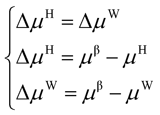
The establishment of the thermodynamic model based on the classical adsorption theory is based on the equilibrium condition that the chemical potential of water in the hydrate phase and the water-rich phase is equal.| μH = μW | (1) |
Suppose the chemical potential (μβ) of an empty hydrate phase (a hypothetical state where water molecules do not occupy the cavities of the crystal lattice) is used as a reference. In this case, the equilibrium conditions can be expressed as follows:
 | (2) |
2.1 Calculation of the ΔμH
In order to link the ΔμH with the observable quantity, van der Waals and Platteeuw26 proposed the following hypothesis:(1) Each cavity can only hold one gas molecule at most.
(2) The cavities are considered to be spherical, and the intermolecular potential energy function can describe the interaction between gas molecules and water molecules on the crystal lattice.
(3) The gas molecules can rotate freely in the cavity.
(4) There is no interaction between gas molecules in different cavities, and gas molecules only interact with the nearest water molecules.
(5) The contribution of water molecules to the free energy of hydrates has nothing to do with the size and type of gas molecules it contains (gas molecules cannot deform the hydrate lattice).
Based on the above assumptions, the following expression of ΔμH can be derived:
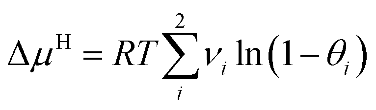 | (3) |
 | (4) |
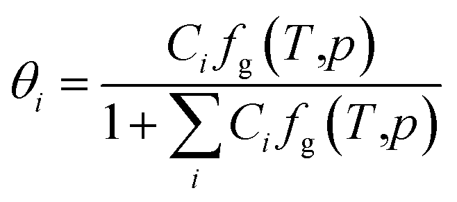
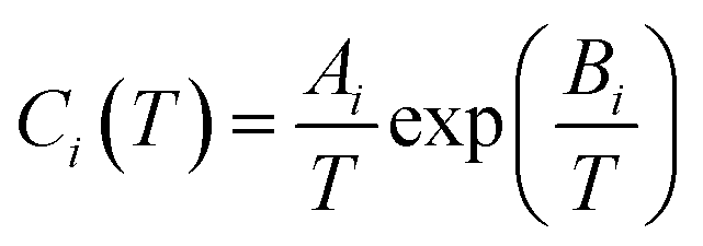
Given the different calculation methods of Ci, a series of thermodynamic models of phase equilibrium of gas hydrate have been developed, such as vdW–P model, Parrish–Prausnitz and John–Holder model.
 | (5) |
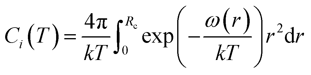
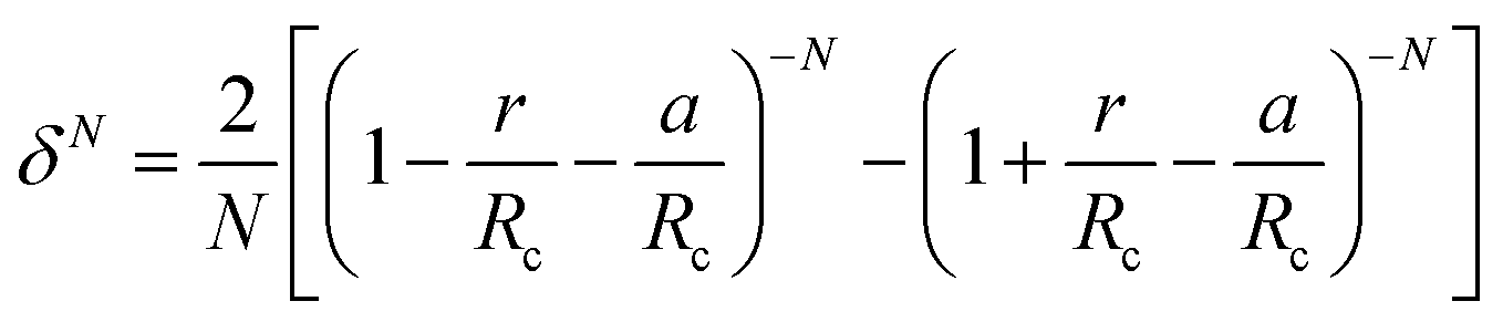
The calculation of ω(r) depends on the molecular potential energy model used. By comparing the calculation results of several molecular potential energy models, McKoy et al.43 found that the Kihara potential energy model is better for dealing with hydrate problems. The ω(r) derived from Kihara's potential energy model is expressed as follows:
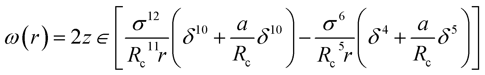 | (6) |
The Kihara potential energy parameters of some gases are shown in Table 1,44 and the calculation equation of σ is as follows:
 | (7) |
| Gas | a (Å) | σ (Å) | ∈/k (Å) |
|---|---|---|---|
| CH4 | 0.3834 | 3.1650 | 154.54 |
| C2H6 | 0.6760 | 3.1383 | 190.80 |
| C3H8 | 0.8340 | 3.1440 | 194.55 |
| N2 | 0.5290 | 0.2569 | 150.03 |
| H2S | 0.4920 | 3.1774 | 198.53 |
| CO2 | 0.17730 | 2.9605 | 170.97 |
 | (8) |
| Gas | Structure I | Structure II | ||||||
|---|---|---|---|---|---|---|---|---|
| Small cavity | Large cavity | Small cavity | Large cavity | |||||
| Ai × 103 | Bi × 10−3 | Ai × 102 | Bi × 10−3 | Ai × 103 | Bi × 10−3 | Ai × 102 | Bi × 10−3 | |
| CH4 | 3.7237 | 2.7088 | 1.8372 | 2.7379 | 2.9560 | 2.6951 | 7.6068 | 2.2027 |
| C2H4 | 0.0830 | 2.3969 | 0.5448 | 3.6638 | 0.0641 | 2.0425 | 3.4940 | 3.1071 |
| C2H6 | 0.0000 | 0.0000 | 0.6906 | 3.6638 | 0.0000 | 0.0000 | 4.0818 | 3.0384 |
| N2 | 3.8087 | 2.2055 | 1.8420 | 2.3013 | 3.0284 | 2.1750 | 7.5149 | 1.8606 |
| H2S | 3.0343 | 3.7360 | 1.6740 | 3.6109 | 2.3758 | 3.7506 | 7.3631 | 2.8541 |
| CO2 | 1.1978 | 2.8605 | 0.8507 | 3.2779 | 0.9091 | 2.6954 | 4.8262 | 2.5718 |
| W(r) = W1(r) + W2(r) + W3(r) | (9) |
| Structure and cavity type | First shell | Second shell | Third shell | n0 | a0 | ||||
|---|---|---|---|---|---|---|---|---|---|
| Rc (Å) | z | Rc (Å) | z | Rc (Å) | z | ||||
| I | Small cavity | 3.875 | 20 | 6.593 | 20 | 8.056 | 50 | 0.973 | 35.345 |
| Large cavity | 4.152 | 21 | 7.078 | 24 | 8.255 | 50 | 0.828 | 14.116 | |
| II | Small cavity | 3.870 | 20 | 6.697 | 20 | 8.079 | 20 | 0.973 | 35.335 |
| Large cavity | 4.703 | 26 | 7.464 | 28 | 8.782 | 50 | 2.313 | 782.847 | |
To account for the influence of non-spherical molecules, John and Holder introduced a disturbance factor Q* to correct the Ci of spherical molecules, that is 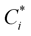 .
.
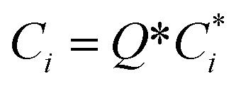 | (10) |
 and the Q* of the spherical molecule are calculated as follows:
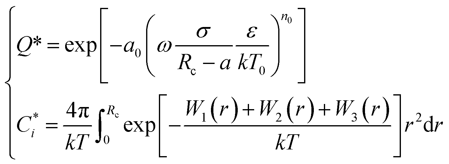 | (11) |
Based on the above assumptions, Chen and Guo30 used statistical thermodynamics to derive the fugacity equation of guest molecules in the hydrate phase based on the kinetic mechanism of hydrate formation, as shown below:
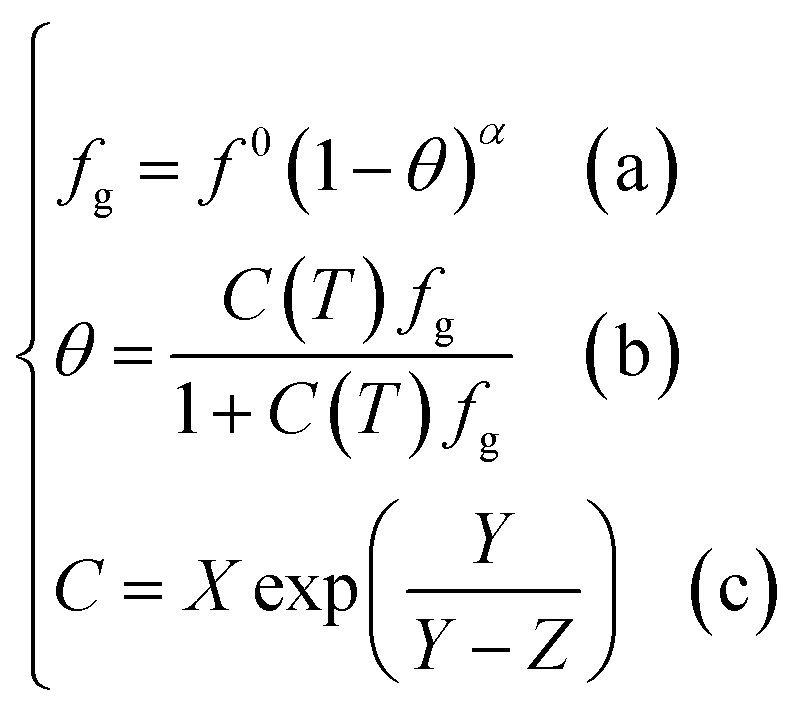 | (12) |
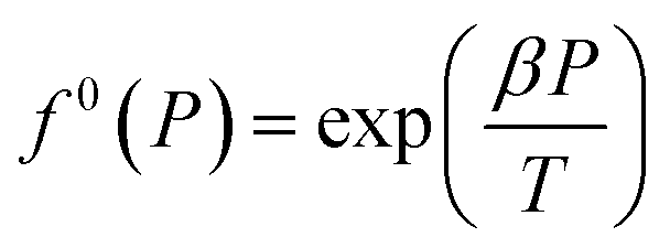
| f0g = f0(T)f0(P)f0(aW) | (13) |
 | (14) |
And f0(aW) can be obtained by the following equation:
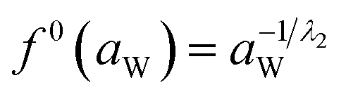 | (15) |
Meanwhile, f0(T) as a function of temperature can be obtained by Antoine equations.
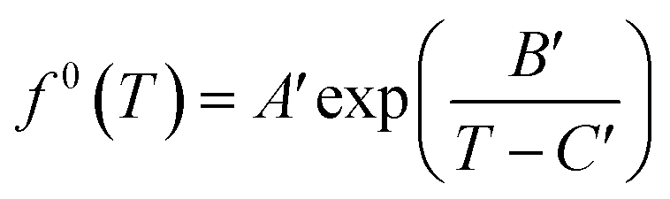 | (16) |
Since most pure gases only form one hydrate structure, the Antoine constants A′, B′ and C′ can be obtained by calculating the formation data of a pure gas hydrate with a particular structure. The Antoine constants of several typical gases are shown in Table 4.
| Gas | Structure I | Structure II | ||||
|---|---|---|---|---|---|---|
| A′ × 1015/Pa | B′/K | C′/K | A′ × 10−28/Pa | B′/K | C′/K | |
| CO2 | 963.72 | −6444.50 | 36.67 | 3.45 | −12570 | 6.79 |
| H2S | 4434.20 | −7540.62 | 31.88 | 3.28 | −13523 | 6.70 |
| CH4 | 1584.40 | −6591.43 | 27.04 | 5.26 | −12955 | 4.08 |
| C2H4 | 48.42 | −5597.59 | 51.80 | 0.04 | −13841 | 0.55 |
| C2H6 | 47.50 | −5465.60 | 57.93 | 0.04 | −11491 | 30.40 |
| C3H6 | 0.95 | −3732.47 | 113.60 | 2.39 | −13968 | 8.78 |
2.2 Calculation of the ΔμW
For the pure water phase (liquid water or ice), the model proposed by Saito et al.27 to calculate ΔμW, that is:
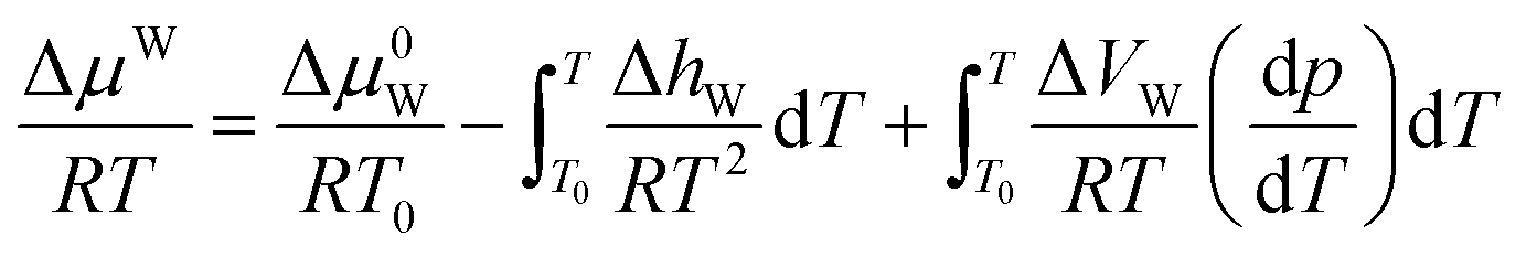 | (17) |
For the water-rich liquid phase containing hydrocarbon solutes, Holder et al.45 assumed that ΔVW is independent of temperature and simplified the above equation:
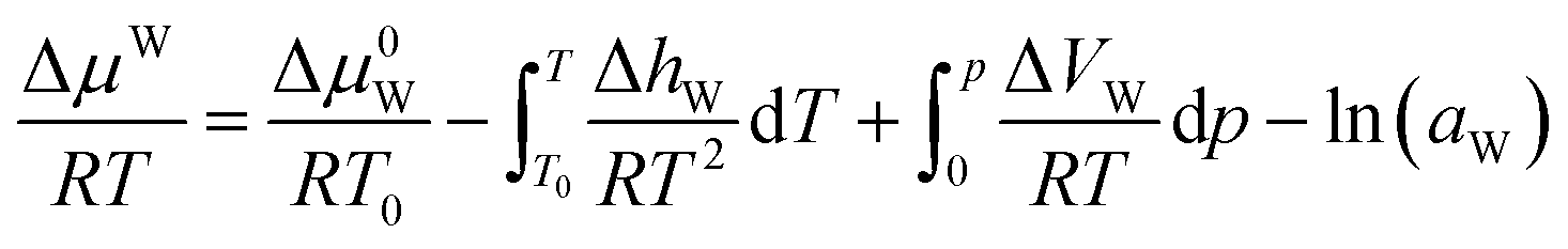 | (18) |
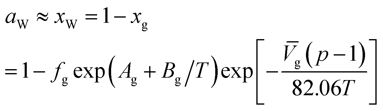 | (19) |
![[V with combining macron]](https://www.rsc.org/images/entities/i_char_0056_0304.gif) g is the partial molar volume of gas molecules in the water-rich liquid phase, 60 for ethylene and 32 for other gas components; Ag and Bg are model constants. The empirical values of Ag and Bg for several typical gases are shown in Table 5.
g is the partial molar volume of gas molecules in the water-rich liquid phase, 60 for ethylene and 32 for other gas components; Ag and Bg are model constants. The empirical values of Ag and Bg for several typical gases are shown in Table 5.
| Gas | Ag | Bg |
|---|---|---|
| N2 | −17.9343 | 1933.3810 |
| O2 | −17.1626 | 1914.1440 |
| H2S | −15.1035 | 2603.9795 |
| CO2 | −14.2831 | 2050.3267 |
| CH4 | −15.8262 | 1559.0631 |
| C2H4 | −18.0579 | 2626.6108 |
| C2H6 | −18.4004 | 2410.4807 |
According to the thermodynamic equation, the molar enthalpy difference (ΔhW) between the completely empty hydrate lattice and the pure water phase can be expressed as follows:
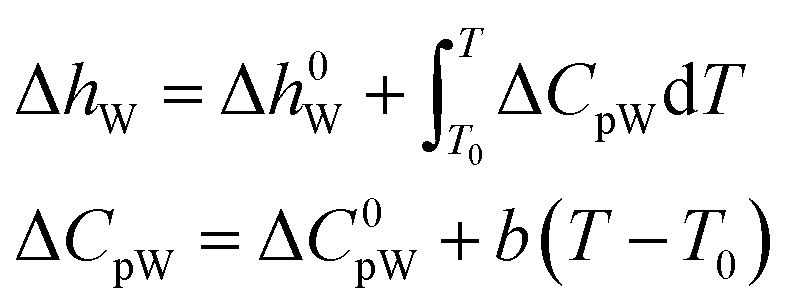 | (20) |
Δμ0W, Δh0W, ΔC0pW, ΔVW, and b must be obtained by regression of experimental data. The empirical values of those parameters of the two hydrates are shown in Table 6.47
| Parameter | Structure I | Structure II |
|---|---|---|
| Δμ0W (J mol−1) | 1120 | 931 |
| Δh0W (J mol−1) | 1714 (T < T0) | 1400 (T < T0) |
| −4297 (T > T0) | −4611 (T > T0) | |
| ΔVW (mL mol−1) | 2.9959 (T < T0 | 3.39644 (T < T0) |
| 4.5959 (T > T0) | 4.99644 (T > T0) | |
| ΔCpW (J mol−1 K−1) | 3.315 + 0.012(T − T0) (T < T0) | 1.029 + 0.004(T − T0) (T < T0) |
| −34.583 + 0.189(T − T0) (T > T0) | −36.861 + 0.181(T − T0) (T > T0) |
Combining the above calculation methods of ΔμH and ΔμW, a set of phase equilibrium thermodynamic models of gas hydrate can be formed. The proposed model can be used to make accurate predictions of formation conditions of gas hydrate. Furthermore, by considering only the effect of inhibitor concentration on water activity, the model can be extended to predict phase equilibria under impure conditions. However, the focus of this paper is to evaluate the optimal range of applicability of various thermodynamic models and to obtain the equation of state that best matches the thermodynamic model. Therefore, we will publish the phase equilibrium prediction model under impure conditions in a subsequent study.
3. Model solution
The vdW–P model, Parrish–Prausnitz model, and John–Holder model are all the thermodynamic models for predicting the phase equilibrium of gas hydrate. However, the method used to obtain the Langmuir constant is different. The vdW–P model and John–Holder model determine the Langmuir constant through the potential energy function, while the Parrish–Prausnitz model uses an empirical equation to calculate it. Therefore, the solving steps of the vdW–P model, Parrish–Prausnitz model, and John–Holder model are the same as the flowchart, that is, they are all solved by eqn (2), (3) and (18).In eqn (3), there are two key parameters that need to be taken. One of is the fugacity of the gas phase, which can be calculated by RK EOS, SRK EOS, PR EOS, PT EOS or BWRS EOS, see Appendix A1. The other is the Langmuir constant of gas, which can be calculated using eqn (5), (8) or (10). The specific calculation steps are as follows, and the solution flow is shown in Fig. 1.
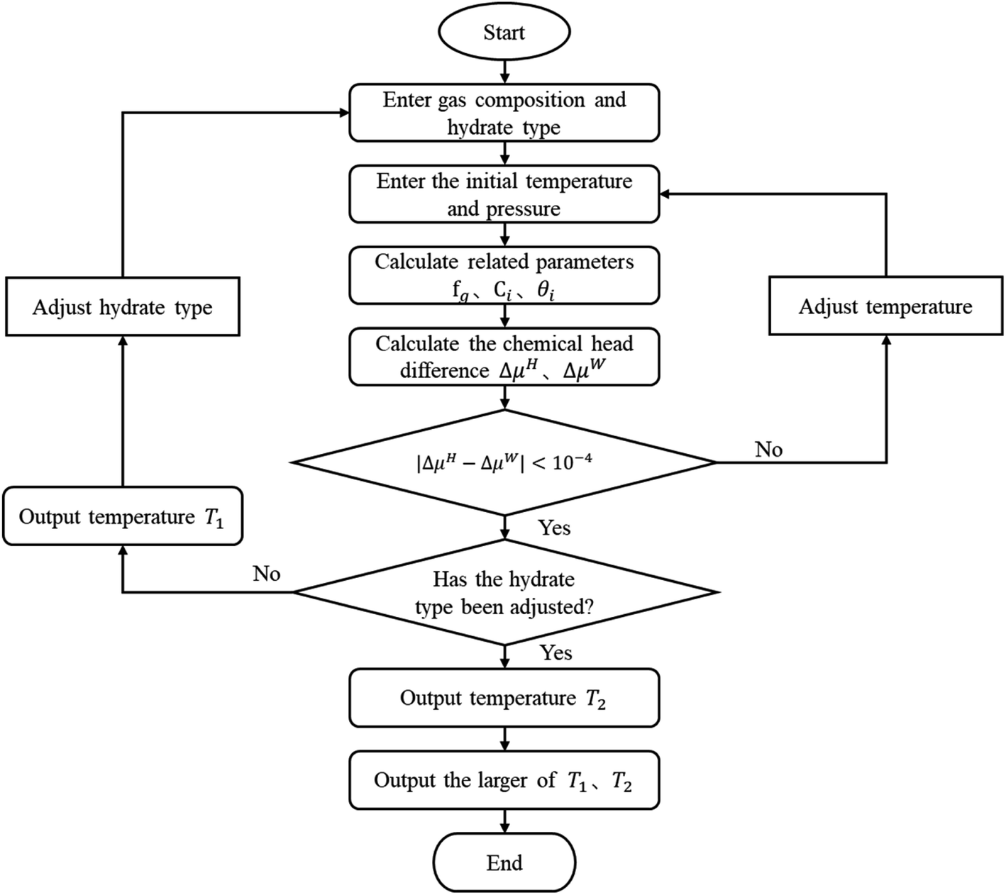 | ||
| Fig. 1 Calculation flow diagram of the vdW–P model, Parrish–Prausnitz model, and John–Holder model. | ||
(1) Assuming the type of hydrate, and input the gas phase composition and formation pressure.
(2) Assign an initial value to the generated temperature (Tg).
(3) Calculate the fugacity of the gas phase using the equation of state according to the gas phase composition.
(4) Find the Langmuir constant.
(5) Calculate θi according to the type of hydrate.
(6) calculate the ΔμH and the ΔμW.
(7) Judge whether the |ΔμH − ΔμW| is less than the set accuracy (here, we set it to 10−4), if this condition is met, the Tg is the phase equilibrium temperature of the type of hydrate, then return to the step (1) to change the hydrate type and calculate again. Otherwise, return to the step (2) to adjust the Tg and recalculate.
(8) Compare the temperature of the two types of formed hydrates, take the higher one as the phase equilibrium temperature of the hydrates, and the corresponding type is the type of hydrates.
Unlike the vdW–P model, the Chen–Guo model is solved by eqn (12) and the equation of state for calculating gas fugacity. The calculation steps of the Chen–Guo model under given pressure conditions are as follows, which calculation process is shown in Fig. 2.
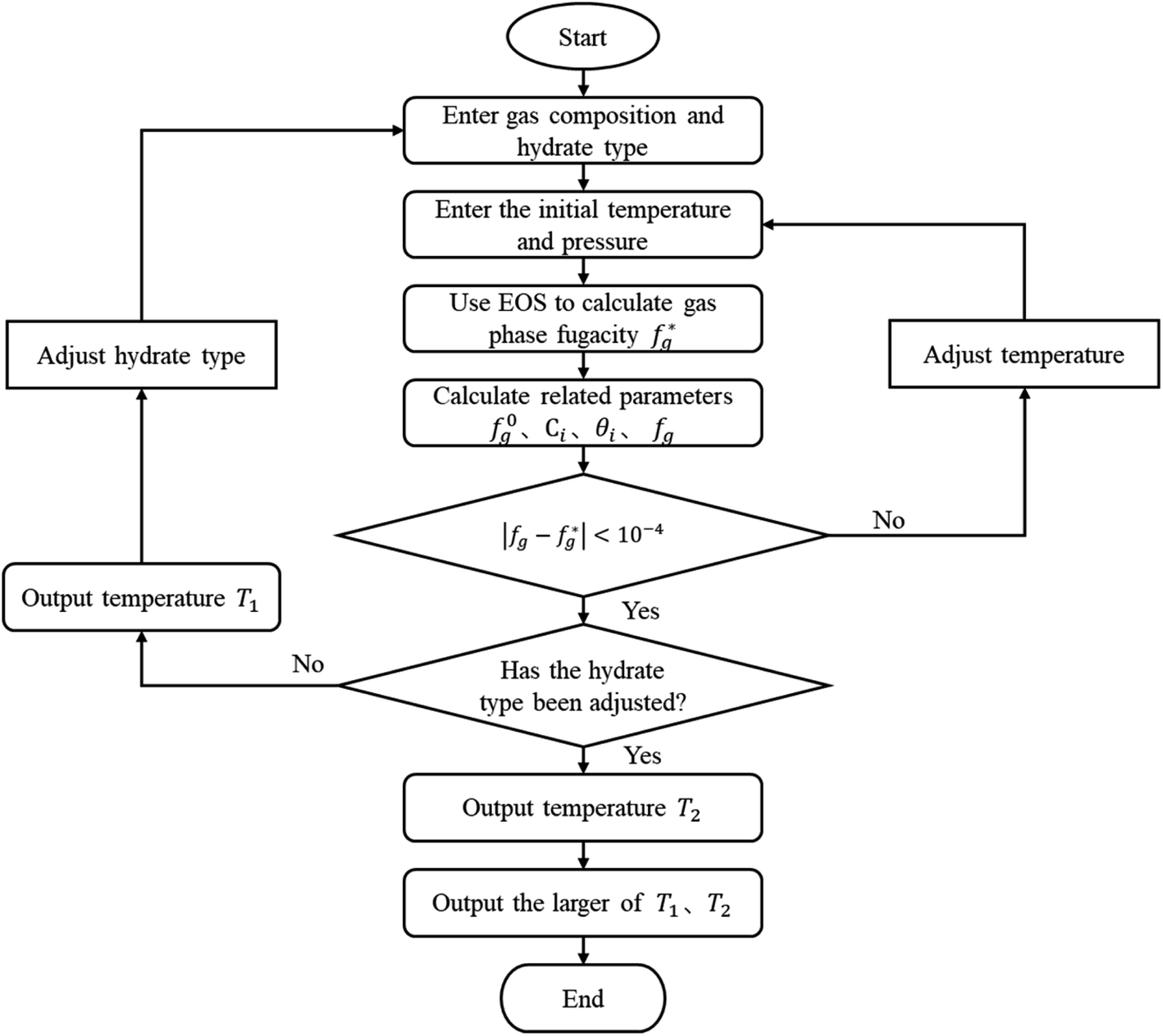 | ||
| Fig. 2 Calculation flow diagram of the Chen–Guo model. | ||
(1) Assuming the type of hydrate, and input the gas phase composition and formation pressure.
(2) Assign an initial value to the generated temperature.
(3) Calculate the  .
.
(4) Calculate the f0g.
(5) Calculate the C using eqn (12c), then calculate the θ using eqn (12b);
(6) Calculate the fg by eqn (12a).
(7) Judge whether the  is less than the set accuracy, if the set accuracy (10−4) is not met, repeat steps (2)–(6) until the requirements are met.
(8) Adjust the hydrate type and recalculate. Then compare the temperature of the two types of formed hydrates, take the higher one as the phase equilibrium temperature of the hydrates, and the corresponding type is the type of hydrates.
4. Results and discussion
This study used four thermodynamic models to calculate the phase equilibrium of the three gas hydrates including methane hydrate, ethane hydrate, and carbon dioxide hydrate in pure water. Based on this, the applicability of different thermodynamic models in different temperature ranges is evaluated. In addition, the influence of the five state equations on the prediction accuracy of the thermodynamic model is compared and analyzed to select the most suitable state equation.A total of 150 data points for the equilibrium of hydrates in pure water were collected through research literature,48–50 which can be seen from Fig. 3. We can clearly understand that the collected methane hydrate phase equilibrium experimental data are concentrated between 274–303 K; ethane hydrate data are distributed between 274–288 K; and carbon dioxide hydrate data are distributed between 274–283 K.
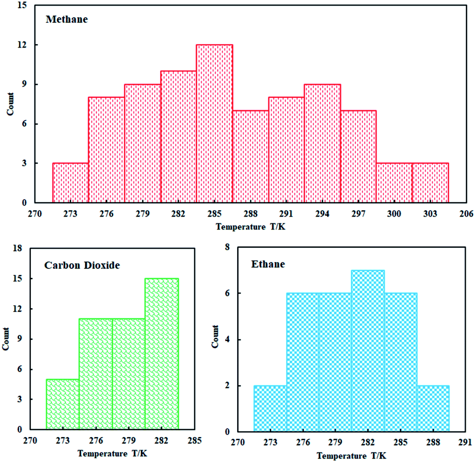 | ||
| Fig. 3 Distribution of experimental data. | ||
We compared the prediction accuracy of different thermodynamic models. The evaluation standard is the average absolute deviation (AADP). The expression of AADP is:
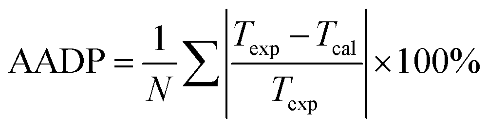 | (21) |
4.1 Comparison of prediction results of different thermal models
Fig. 4(a) shows the comparison curve between the predicted and experimental value of methane hydrate phase equilibrium by different thermodynamic models. The four thermodynamic models are unified using SRK EOS to calculate the fugacity of gas phase. It can be seen from the figure that the trend of the phase equilibrium curve of methane hydrate predicted by the four thermodynamic models are the same. As the temperature increases, the prediction result of the Parrish–Prausnitz model is gradually lower than the experimental value. Only the John–Holder model and Chen–Guo model are relatively close to the experimental value. In addition, due to the influence of the non-spherical cavity when the John–Holder model calculates the potential energy, the prediction result of the John–Holder model is closer to the experimental value than the vdW–P model.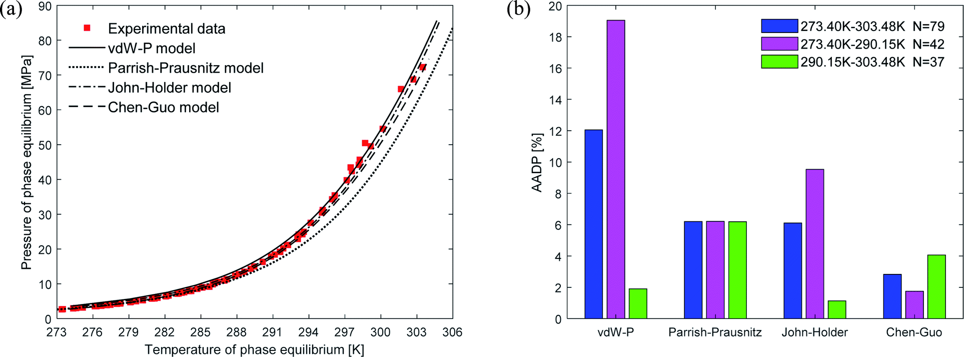 | ||
| Fig. 4 Comparison of prediction results of phase equilibrium of methane hydrate under different thermodynamic model conditions. (a) Comparison of prediction results of phase equilibrium. (b) Average absolute deviation of different thermodynamic models. | ||
Fig. 4(b) describes the statistical prediction error of each thermodynamic model. It is easy to find from the figure that the AADP of each thermodynamic model in the broad temperature range of 273.40–303.48 K is 12.04%, 6.19%, 6.10%, 2.83%, respectively. The Chen–Guo model is better than other thermodynamic models in predicting the equilibrium temperature of CH4 hydrate in this temperature range. However, in the temperature range of 290.15–303.48 K, the predicted accuracy of the Chen–Guo model (4.05%) is lower than the John–Holder model (1.13%). Which indicates that choosing a suitable thermodynamic model in different temperature ranges is very meaningful to improve the prediction accuracy of phase equilibrium of methane hydrate.
Fig. 5(a) depicts the comparison between the predicted values and experimental values of carbon dioxide hydrate phase equilibrium under different thermodynamic model conditions. It can be seen from the figure that the predicted values of the vdW–P model and the Parrish–Prausnitz model are lower than the experimental values, while the John–Holder model and the Chen–Guo model are relatively close. In particular, as the temperature increases, there is a considerable deviation between the predicted value of the Parrish–Prausnitz model and the experimental value. Which shows that the empirical equation for calculating the Langmuir constant in the Parrish–Prausnitz model under high-temperature conditions is no longer applicable. From Fig. 5(b), it is found that in the temperature range of 273.44 K to 283.09 K, the AADP for each thermal model is 6.23%, 20.16%, 0.60%, and 4.18%, respectively. Therefore, under this temperature range, the John–Holder model performances best in predicting the phase equilibrium of carbon dioxide hydrate.
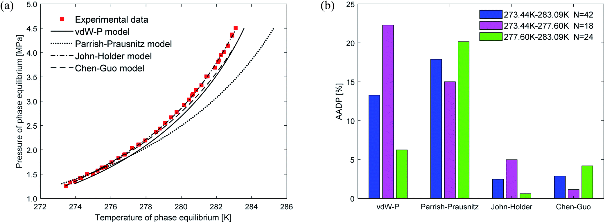 | ||
| Fig. 5 Comparison of prediction results of phase equilibrium of carbon dioxide hydrate under different thermodynamic model conditions. (a) Comparison of prediction results of phase equilibrium. (b) Average absolute deviation of different thermodynamic models. | ||
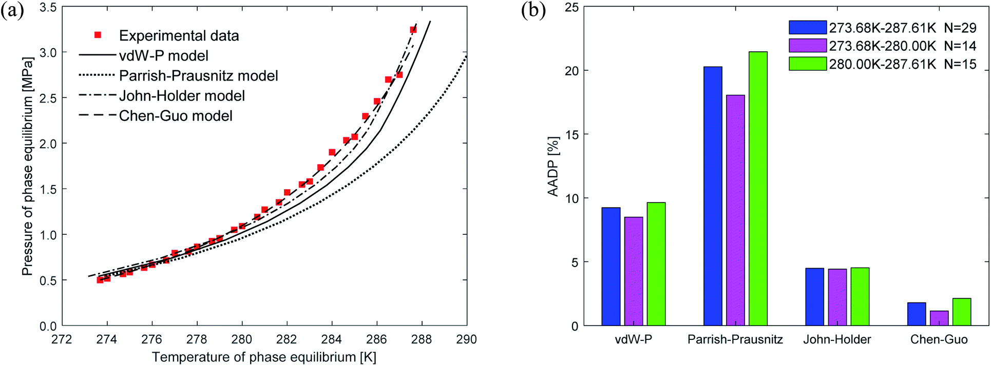
Fig. 6 shows the prediction results of phase equilibrium of ethane hydrate in different thermodynamic models. It can be found from the figure that as the temperature increases, the predicted values of the vdW–P model and the Parrish–Prausnitz model are gradually lower than the experimental values. Only the predicted values of the John–Holder model and the Chen–Guo model are close to the experimental values. It can be seen from Fig. 6(b) that in the temperature range of 273.68–287.6 K, the AADP of the ethane hydrate phase equilibrium predicted by each thermodynamic model is 9.23%, 20.26%, 4.48%, and 1.78%, respectively. This means that the Chen–Guo model is selected to predict the phase equilibrium of ethane hydrate with the highest accuracy in this temperature range.
 | ||
| Fig. 6 Comparison of prediction results of phase equilibrium of ethane hydrate under different thermodynamic model conditions. (a) Comparison of prediction results of phase equilibrium. (b) Average absolute deviation of different thermodynamic models. | ||
4.2 The influence of the equation of state on the predicted results
When using thermodynamic models to predict the phase equilibrium of gas hydrates, the gas phase fugacity is one of the critical parameters that affect the accuracy of the prediction results. In this study, five state equations are applied to the same thermodynamic model in turn, then the state equation most suitable for the thermodynamic model is selected. The effect of the state equation on the vdW–P model, Parrish–Prausnitz model, and John–Holder model is the same because they all have the same solution steps. Therefore, this study only uses the vdW–P model and Chen–Guo model for calculation and analysis.Fig. 7 depicts the comparison between the between the predicted values and experimental values of phase equilibrium of methane hydrate in pure water under different equations of state. It's easy to find that the overall trends of the predicted phase equilibrium curves of the vdW–P model and the Chen–Guo model are the same under the five different state equation conditions. For the vdW–P model, as the temperature increases, the results predicted by the RK, PR, and PT equations of state are gradually higher than the experimental values. Among them, the results predicted by the PR equation of state have the highest degree of deviation. The BWRS expected result is the closest to the experimental value. Which can be shown in Fig. 7(a). It can be seen from Fig. 7(b) that the AADP predicted by the five equations of state in the vdW–P model under the temperature range of 273.40–303.48 K is 13.52%, 12.04%, 17.69%, 13.57%, and 13.32%, respectively.
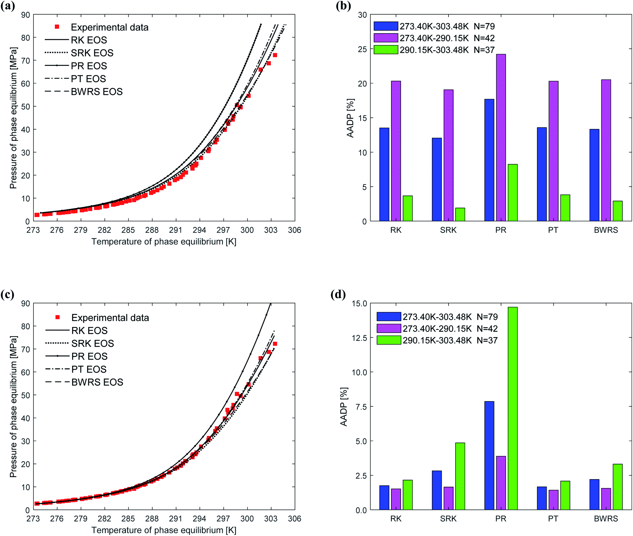 | ||
| Fig. 7 Comparison of prediction results of phase equilibrium of methane hydrate under different state equations. (a) Predicted values of vdW–P model. (b) Mean absolute deviation of the vdW–P model. (c) Predicted values of Chen–Guo model. (d) Mean absolute deviation of the Chen–Guo model. | ||
As shown in Fig. 7(c), as the temperature rises, the results predicted by the Chen–Guo model using the PR EOS are gradually higher than the experimental value, and the results predicted by the SRK EOS and BWRS EOS are progressively lower than the experimental value. In contrast, the results predicted by the RK EOS and PT EOS are relatively close to the experimental values. When the temperature is higher than 300 K, the result predicted by the PT is closer to the experimental value than the result predicted by the RK. It can be seen from Fig. 7(d) that the AADP of Chen–Guo model uses the five state equations is 1.75%, 2.83%, 7.86%, 1.67%, and 2.21%, respectively. This means that the Chen–Guo model uses the PT EOS to predict phase equilibrium of methane hydrate with the highest accuracy in the broad temperature range of 273.40–303.48 K. At the same time, this shows that the choice of the state equation greatly influences the prediction accuracy of the thermodynamic model, too.
Fig. 8 depicts the comparison between the predicted values and experimental values of phase equilibrium of carbon dioxide hydrate in pure water under different equations of state. It can be seen from Fig. 8(a) that the results predicted by the five equations of state of the vdW–P model have slight differences. With the increase of temperature, the results are all lower than the experimental values, and the results predicted by the PR is closest. It can be found from Fig. 8(b) that the AADP predicted by the five equations of state in the vdW–P model in the temperature range of 273.44–383.09 K is 15.15%, 13.94%, 10.86%, 11.48%, and 12.17%.
 | ||
| Fig. 8 Comparison of prediction results of phase equilibrium of carbon dioxide hydrate under different state equations. (a) Predicted values of vdW–P model. (b) Mean absolute deviation of the vdW–P model. (c) Predicted values of Chen–Guo model. (d) Mean absolute deviation of the Chen–Guo model. | ||
It can be seen from Fig. 8(c) that the phase equilibrium curves predicted by the Chen–Guo model using different equations of state coincide. Therefore, for carbon dioxide hydrate, the choice of the equation of state has little effect on the prediction accuracy of the Chen–Guo model. It's easy to find from Fig. 8(d) that the AADP corresponding to the five equations of state is 3.48%, 2.88%, 1.45%, 1.67%, and 1.97%, respectively. Therefore, in the range of 273.36–283.3 K, the Chen–Guo model uses the PR equation of state to predict the phase equilibrium of carbon dioxide hydrate with the highest accuracy.
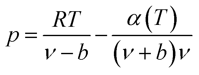
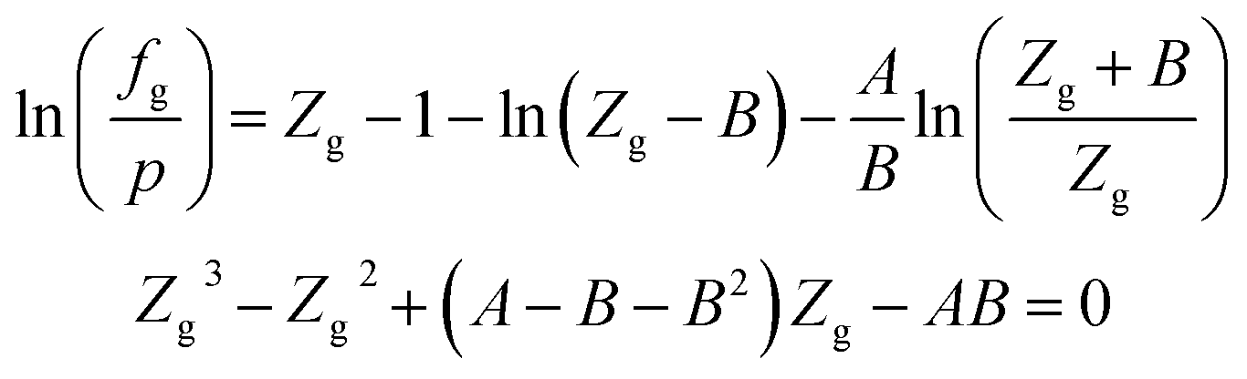
Fig. 9 shows the comparison between the predicted values and experimental values of the phase equilibrium of ethane hydrate under different equations of state. It can be seen from Fig. 9(a) that the prediction results of the vdW–P model using the PR EOS and PT EOS are relatively close to the experimental values. However, as the temperature increases, the prediction results of the vdW–P model using the RK, SRK, and BWRS are gradually lower than the experimental values. It can be found from Fig. 9(b) that the AADP predicted by the vdW–P model under different equations of state conditions is 8.68%, 8.40%, 4.48%, 5.24%, and 11.48%, respectively. This also shows that the choice of the state equation greatly influences the prediction results of the vdW–P model.
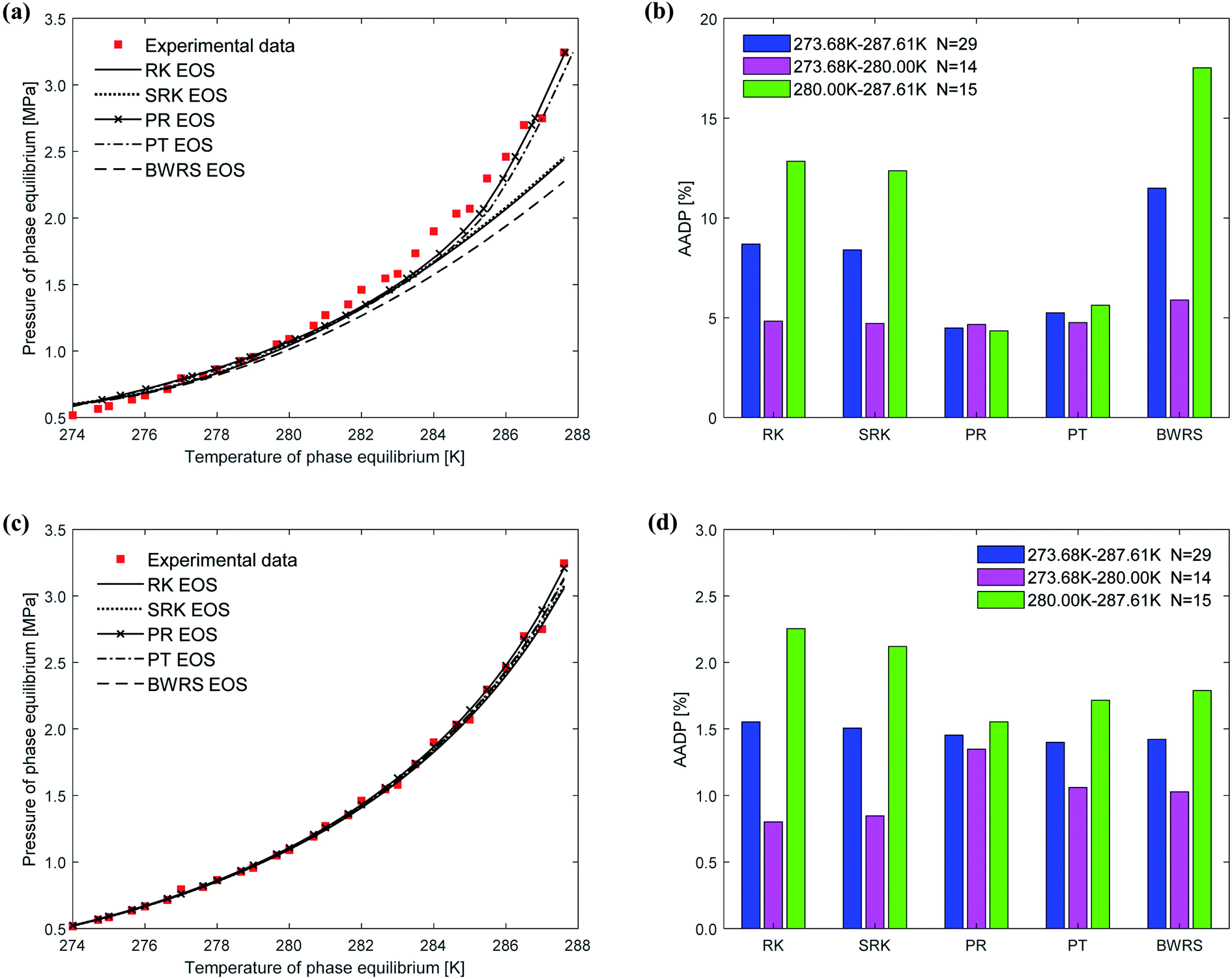 | ||
| Fig. 9 Comparison of prediction results of phase equilibrium of ethane hydrate under different state equations. (a) Predicted values of vdW–P model. (b) Mean absolute deviation of the vdW–P model. (c) Predicted values of Chen–Guo model. (d) Mean absolute deviation of the Chen–Guo model. | ||
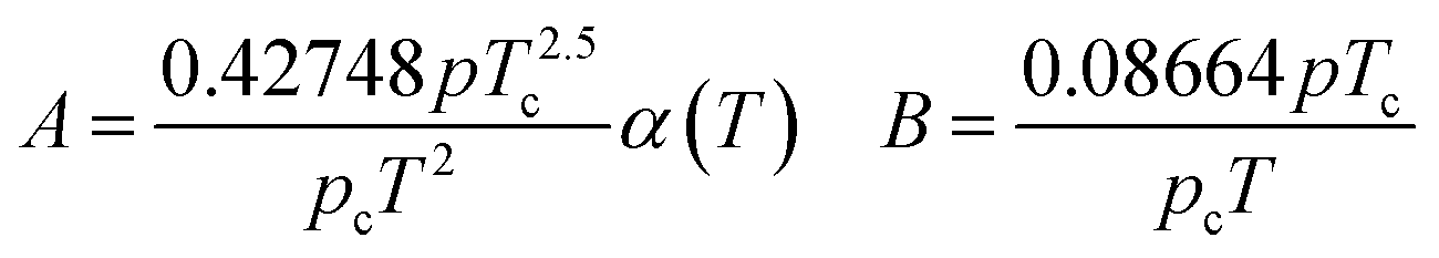
The phase equilibrium of ethane hydrate curves predicted by the Chen–Guo model under different equations of state coincides, which can be shown in Fig. 9(c). This shows that for ethane hydrate, the choice of the equation of state has little effect on the prediction accuracy of the Chen–Guo model. It can be seen from Fig. 9(d) that the AADP corresponding to five state equations are 1.55%, 1.50%, 1.45%, 1.39%, 1.42%, respectively. Therefore, the Chen–Guo model uses the PT equation of state to predict the phase equilibrium of ethane hydrate with the highest accuracy in the temperature range of 273.68–287.61 K.
5. Conclusions
In order to improve the accuracy of gas hydrate prediction, this study is based on a thermodynamic model and fully considers the changes in water activity caused by gas dissolution. The prediction results of different types of gas hydrates under various temperature ranges and different equations of state are compared. Furthermore, the thermodynamic model with the highest prediction accuracy and the corresponding equation of state is optimized. Through the verification of experimental data, this study draws the following conclusions:(1) For CH4 and C2H6, the Chen–Guo model predicts better results than other thermodynamic models overall. CO2 and C2H6 in comparison with CH4, the prediction accuracy of the John–Holder model, which incorporates the effect of spherical asymmetry, is higher than that of the vdW–P model and the Parrish–Prausnitz model, referring to Fig. 4–6 in this manuscript.
(2) The higher the predicted temperature, the farther the Parrish–Prausnitz model predictions deviate from the experimental values, indicating that the empirical formula for calculating the Langmuir adsorption constants in the Parrish–Prausnitz model is no longer applicable under high temperature conditions.
(3) The vdW–P model is sensitive to the choice of state equation compared to the Chen–Guo model. The prediction results of the vdW–P model vary widely with the choice of different equations of state, especially for ethane hydrate. vdW–P model and Chen–Guo model select the PT equation of state with the highest prediction accuracy compared with other equation of state, see Fig. 7–9 in this paper.
Appendix A
RK EOS
The expression of the RK state equation is as follows:
 | (A-1) |
Among, α(T) = T−0.5.
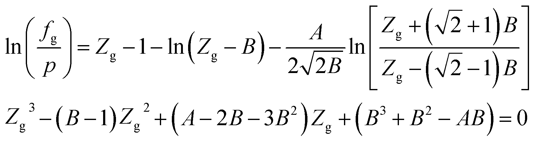
When the RK EOS is used, the gas phase fugacity fg can be expressed as:
 | (A-2) |
In eqn (A-2), Zg takes the largest real root, and the expressions of A and B are:
 | (A-3) |
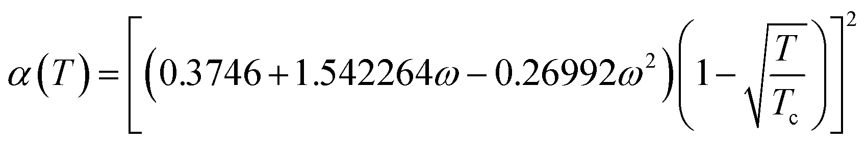
SRK EOS
Using the SRK EOS to calculate the gas phase fugacity fg is consistent with the RK equation of state calculation method, only the expressions of α(T) and A are different, namely.
 | (A-4) |
PR EOS
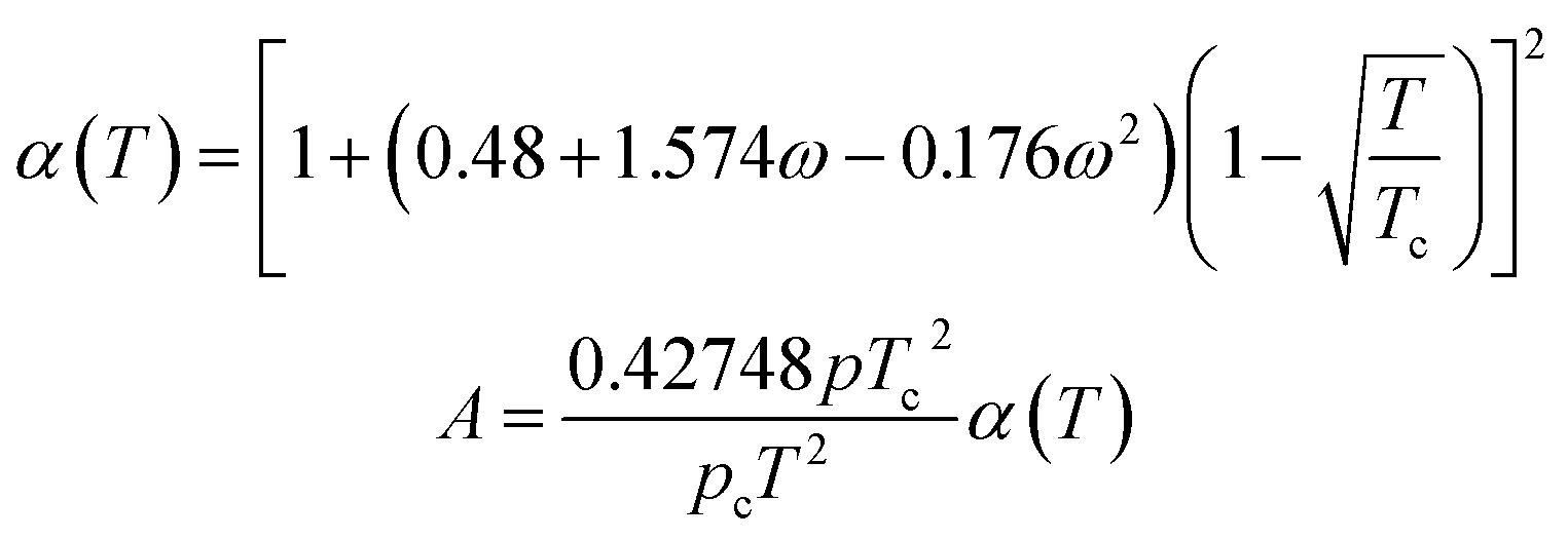
The expression of the PR state equation is as follows:
 | (A-5) |
In the equation, the expression of α(T) is as follows:
 | (A-6) |
When using the PR equation of state, the gas phase fugacity fg is expressed as follows:
 | (A-7) |
In eqn (A-7), Zg takes the largest real root, and the expressions of A and B are:
 | (A-8) |
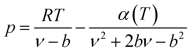
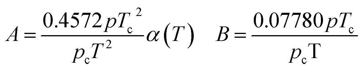
PT EOS
The expression of the PT state equation is as follows:
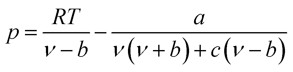 | (A-9) |
When using the PT equation of state, the gas phase fugacity fg is expressed as follows:
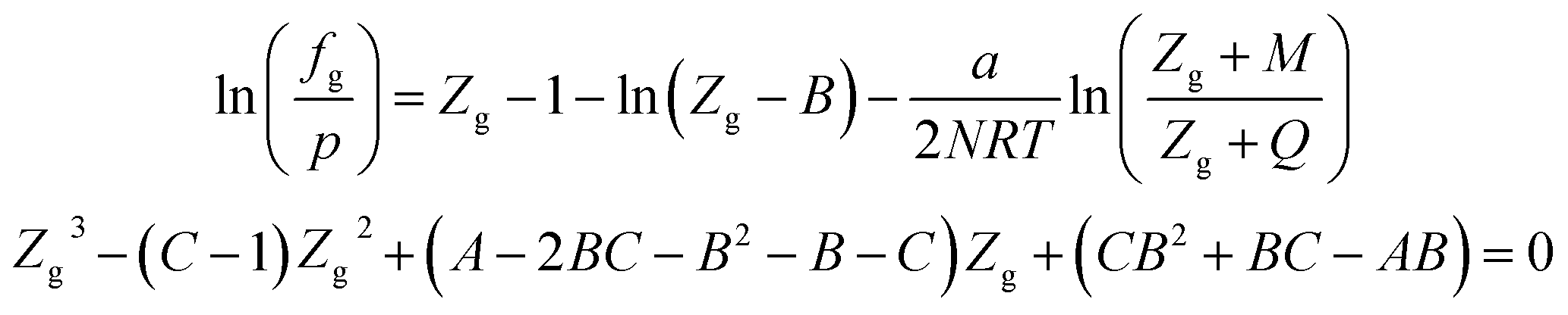 | (A-10) |
In eqn (A-7), Zg takes the largest real root, and the expressions of A, B, C, a, b, c are:
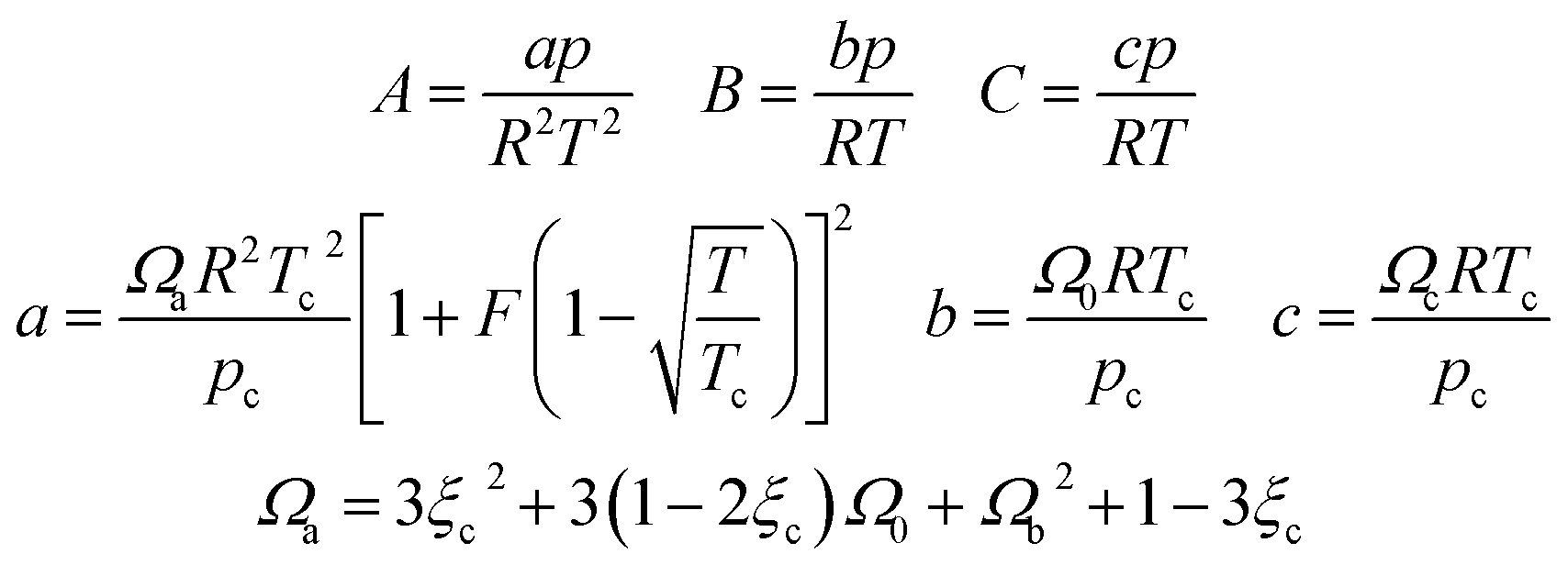 | (A-11) |
In this study, the values of F and ξc can be obtained in the literature,51 and the value of Ωb is the smallest positive root of eqn (12), which is expressed as follows:
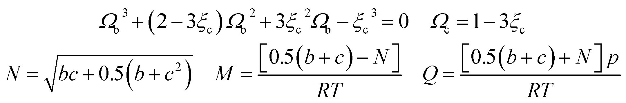 | (A-12) |
BWRS EOS
The BWRS equation is a multi-parameter state equation, and its form is:
 | (A-13) |
In the eqn (A-13), A, B, C, D, E, a, b, c, d, α, γ are the 11 parameters of the equation of state, all of which can be determined by its critical parameters Tc, pc, ρc and eccentricity factor ω.
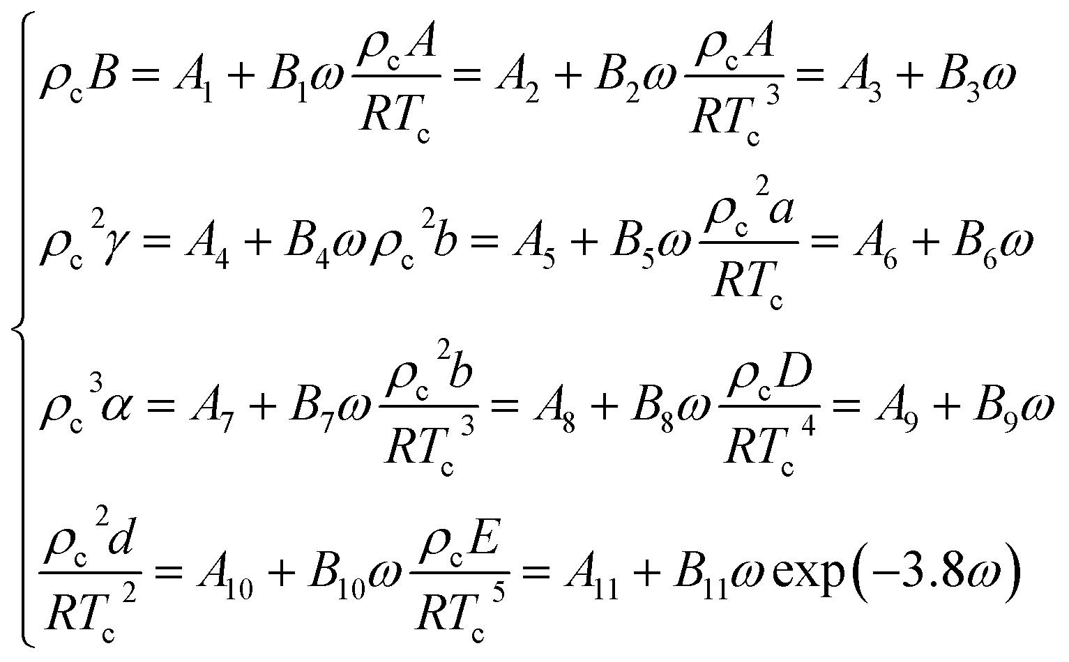 | (A-14) |
The relevant parameters in eqn (A-14) and the physical parameters of natural gas pure gas substances can be found in the literature.52
When using the BWRS equation of state, the gas phase fugacity fg is expressed as follows:
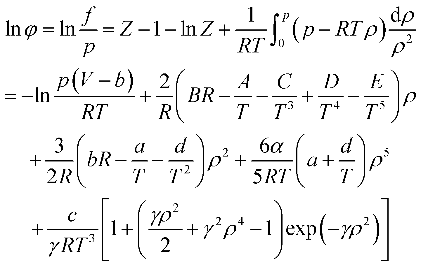 | (A-15) |
Abbreviations
| μH | Chemical potential of water in hydrate phase |
| μβ | Chemical potential of empty hydrate phase |
| ΔμW | Chemical potential deviation of water in water-rich phase |
| T | Temperature, K |
| θi | Ratio of i-type pores occupied by guest molecules |
| fg | Gas fugacity, Pa |
| Rc | Radius of cavity |
| z | Coordination number |
| σ | Distance between the molecular nuclei, Å |
| n0, a0 | Characteristic constants of the cavity |
| aW | Water activity |
| ΔVW | Molar volume difference |
| μW | Chemical potential of water in water-rich phase |
| ΔμH | Chemical potential deviation of water in hydrate phase |
| R | Gas constant, 8.314 J (K−1 mol−1) |
| νi | Number of i-type pores per water molecule |
| Ci | Langmuir gas adsorption constant of guest molecules in i-type cavities |
| k | Boltzmann constant, 1.38062 × 10⁻²³ J K−1 |
| ω | Sum of the potential energy in the hydrate lattice cavity |
| a | Radius of the molecular core, Å |
| Q* | Disturbance factor |
| f0g | Gas phase fugacity of basic unfilled hydrate |
| ΔhW | Molar enthalpy difference of water |
| xg | Gas solubility |
Conflicts of interest
There are no conflicts to declare.Acknowledgements
The work was supported by the National Natural Science Foundation of China (no. 51734010) and the Science Foundation of China University of Petroleum, Beijing (no. 2462020XKBH011).References
- E. D. Sloan, Fundamental principles and applications of natural gas hydrates, Nature, 2003, 426, 353–359 CrossRef CAS PubMed.
- Y. F. Makogon, Natural gas hydrates–a promising source of energy, J. Nat. Gas Sci. Eng., 2010, 2, 49–59 CrossRef CAS.
- M. Zi, D. Chen, J. Wang, P. Hu and G. Wu, Kinetic and rheological study of methane hydrate formation in water-in-oil emulsion: Effects of emulsion composition and silica sands, Fuel, 2019, 255, 115708 CrossRef CAS.
- Y. F. Makogon, Perspectives for the development of gas hydrate deposits, Gas Hydrates and Permafrost, Proceedings of the 4th Canadian Permafrost Conference, 1982, pp. 299–304 Search PubMed.
- E. D. Sloan Jr and C. A. Koh, Clathrate Hydrates of Natural Gases, CRC press, 2007 Search PubMed.
- J. Carroll, Natural Gas Hydrates: A Guide for Engineers, Gulf Professional Publishing, Cambridge, 2020 Search PubMed.
- E. Hammerschmidt, Formation of gas hydrates in natural gas transmission lines, Ind. Eng. Chem., 1934, 26, 851–855 CrossRef CAS.
- J. Wang, F. Han and S. Li, et al., Investigation of gas hydrate production with salinity via depressurization and thermal stimulation methods, J. Pet. Sci. Eng., 2020, 194, 107465 CrossRef CAS.
- X. Zhang, B. R. Lee, J.-H. Sa, K. J. Kinnari, K. M. Askvik, X. Li and A. K. Sum, Hydrate management in deadlegs: effect of wall temperature on hydrate deposition, Energy Fuels, 2018, 32, 3254–3262 CrossRef CAS.
- M. Zi, G. Wu, J. Wang and D. Chen, Investigation of gas hydrate formation and inhibition in oil-water system containing model asphaltene, Chem. Eng. J., 2021, 412, 128452 CrossRef CAS.
- D. E. Sloan and C. A. Koh, Clathrate Hydrates of Natural Gases, CRC Press, Boca Raton, 3rd edn, 2008 Search PubMed.
- B. F. Towler and S. Mokhatab, Quickly estimate hydrate formation conditions in natural gases, Hydrocarb Process, 2005, pp. 61–62 Search PubMed.
- M. A. Mahabadian, A. Chapoy, R. Burgass and B. Tohidi, Development of a multiphase flash in presence of hydrates: Experimental measurements and validation with the CPA equation of state, Fluid Phase Equilib., 2016, 414, 117–132 CrossRef CAS.
- M. M. Ghiasi, Initial estimation of hydrate formation temperature of sweet natural gases based on new empirical correlation, J. Nat. Gas Chem., 2012, 21, 508–512 CrossRef CAS.
- M. D. Jager and E. D. Sloan, The effect of pressure on methane hydration in pure water and sodium chloride solutions, Fluid Phase Equilib., 2001, 185, 89–99 CrossRef CAS.
- S. Chavoshi, M. Safamirzaei and F. P. Shariati, Evaluation of empirical correlations for predicting gas hydrate formation temperature, Gas Process. J., 2018, 6, 15–36 Search PubMed.
- M. Safamirzaei, Predict gas hydrate formation temperature with a simple correlation, Gas Process. Mag., 2015, 51–54 CAS.
- G. Zahedi, Z. Karami and H. Yaghoobi, Prediction of hydrate formation temperature by both statistical models and artificial neural network approaches, Energy Convers. Manage., 2009, 50, 2052–2059 CrossRef CAS.
- E. Khamehchi, E. Shamohammadi and S. H. Yousef, Predicting the hydrate formation temperature by a new correlation and neural network, Gas Process. J., 2013, 1, 41–50 Search PubMed.
- E. Soroush, M. Mesbah, A. Shokrollahi, J. Rozyn, M. Lee, T. Kashiwao and A. Bahadori, Evolving a robust modeling tool for prediction of natural gas hydrate formation conditions, J. Unconv. Oil Gas Resour., 2015, 12, 45–55 CrossRef.
- M. Mohamadi-Baghmolaei, A. Hajizadeh, R. Azin and A. A. Izadpanah, Assessing thermodynamic models and introducing novel method for prediction of methane hydrate formation, J. Pet. Explor. Prod. Technol., 2018, 8, 1401–1412 CrossRef CAS.
- A. Eslamimanesh, A. H. Mohammadi and D. Richon, Thermodynamic model for predicting phase equilibria of simple clathrate hydrates of refrigerants, Chem. Eng. Sci., 2011, 66, 5439–5445 CrossRef CAS.
- W. R. Parrish and J. M. Prausnitz, Dissociation pressures of gas hydrates formed by gas mixtures, Ind. Eng. Chem. Process Des. Dev., 1972, 11, 26–35 CrossRef CAS.
- V. T. John, K. D. Papadopoulos and G. D. Holder, A generalized model for predicting equilibrium conditions for gas hydrates, AIChE J., 1985, 31, 252–259 CrossRef CAS.
- M. Illbeigi, A. Fazlali and A. H. Mohammadi, Thermodynamic model for the prediction of equilibrium conditions of clathrate hydrates of methane + water-soluble or -insoluble hydrate former, Ind. Eng. Chem. Res., 2011, 50, 9437–9450 CrossRef CAS.
- J. H. Van der Waals and J. C. Platteeuw, Clathrate solutions, Adv. Chem. Phys., 1959, 2, 1–57 CAS.
- S. Saito, D. R. Marshall and R. Kobayashi, Hydrates at high pressures: Part II. Application of statistical mechanics to the study of the hydrates of methane, argon, and nitrogen, AIChE J., 1964, 10(5), 734–740 CrossRef CAS.
- W. R. Parrish and J. M. Prausnitz, Dissociation pressures of gas hydrates formed by gas mixtures, Ind. Eng. Chem. Process Des. Dev., 1972, 11(1), 26–35 CrossRef CAS.
- V. T. John, K. D. Papadopoulos and G. D. Holder, A generalized model for predicting equilibrium conditions for gas hydrates, AIChE J., 1985, 31(2), 252–259 CrossRef CAS.
- G. J. Chen and T. M. Guo, A new approach to gas hydrate modelling, Chem. Eng. J., 1998, 71(2), 145–151 CrossRef CAS.
- J. Javanmardi, M. Moshfeghian and R. N. Maddox, An accurate model for prediction of gas hydrate formation conditions in mixtures of aqueous electrolyte solutions and alcohol, Can. J. Chem. Eng., 2001, 79, 367–373 CrossRef CAS.
- S. Li, Y. Li and J. Wang, et al., Prediction of gas hydrate formation conditions in the presence of electrolytes using an N-NRTL-NRF activity coefficient model, Ind. Eng. Chem. Res., 2020, 59(13), 6269–6278 CrossRef CAS.
- S. Li, Y. Li and L. Yang, et al., Prediction of equilibrium conditions for gas hydrates in the organic inhibitor aqueous solutions using a thermodynamic consistency-based model, Fluid Phase Equilib., 2021, 113118 CrossRef CAS.
- G. Moradi and E. Khosravani, Modeling of hydrate formation conditions for CH4, C2H6, C3H8, N2, CO2 and their mixtures using the PRSV2 equation of state and obtaining the Kihara potential parameters for these components, Fluid Phase Equilib., 2013, 338, 179–187 CrossRef CAS.
- J. B. Klauda and S. I. Sandler, A fugacity model for gas hydrate phase equilibria, Ind. Eng. Chem. Res., 2000, 39(9), 3377–3386 CrossRef CAS.
- S. A. Naghibzade, H. Kharrazi and A. S. Mehri, Comparison of different equations of state in a model based on VdW-P for prediction of CO2 hydrate formation pressure in Lw-H-V phase and a new correlation to degrade error of the model, J. Nat. Gas Sci. Eng., 2015, 22(6), 292–298 CrossRef CAS.
- J. Y. Pang, H. J. Ng and J. L. Zuo, et al., Hydrogen gas hydrate measurements and predictions, Fluid Phase Equilib., 2012, 316, 6–10 CrossRef CAS.
- A. Joshi, P. Mekala and J. S. Sangwai, Modeling phase equilibria of semiclathrate hydrates of CH4, CO2 and N2 in aqueous solution of tetra-n-butyl ammonium bromide, J. Nat. Gas Chem., 2012, 21(4), 459–465 CrossRef CAS.
- T. Barmavath, A. P. Mekal and J. S. Sangwai, Prediction of phase stability conditions of gas hydrates of methane and carbon dioxide in porous media, J. Nat. Gas Sci. Eng., 2014, 18(14), 254–262 CrossRef CAS.
- V. R. Avula, R. L. Gardas and J. S. Sangwai, An improved model for the phase equilibrium of methane hydrate inhibition in the presence of ionic liquids, Fluid Phase Equilib., 2014, 382, 187–196 CrossRef CAS.
- L. L. Shi and D. Q. Liang, Thermodynamic model of phase equilibria of tetrabutyl ammonium halide (fluoride, chloride, or bromide) plus methane or carbon dioxide semiclathrate hydrates, Fluid Phase Equilib., 2015, 386, 149–154 CrossRef CAS.
- Z. Liu, Research on Natural Gas Hydrate Formation and Thermodynamic Model, China University of Petroleum, Qingdao (East China), 2007 Search PubMed.
- V. McKoy and O. Sinanoğlu, Theory of dissociation pressures of some gas hydrates, J. Chem. Phys., 1963, 38(12), 2946–2956 CrossRef CAS.
- A. P. Mehta and E. D. Sloan, Improved thermodynamic parameters for prediction of structure H hydrate equilibria, AIChE J., 1996, 42(7), 2036–2046 CrossRef CAS.
- G. D. Holder, G. Corbin and K. D. Papadopoulos, Ind. Eng. Chem. Fundam., 1980, 19, 282–286 CrossRef CAS.
- V. A. Kuustraa and E. C. Hammershaimb, Handbook of gas hydrate properties and occurrence, Lewin and Associates, Inc., Washington, DC (USA), 1983 Search PubMed.
- V. T. John, K. D. Papadopoulos and G. D. Holder, A generalized model for predicting equilibrium conditions for gas hydrates, AIChE J., 1985, 31(2), 252–259 CrossRef CAS.
- J. Nixdorf and L. R. Oellrich, Experimental determination of hydrate equilibrium conditions for pure gases, binary and ternary mixtures and natural gases, Fluid Phase Equilib., 1997, 139(1–2), 325–333 CrossRef CAS.
- P. Gayet, C. Dicharry and G. Marion, et al., Experimental determination of methane hydrate dissociation curve up to 55 MPa by using a small amount of surfactant as hydrate promoter, Chem. Eng. Sci., 2005, 60(21), 5751–5758 CrossRef CAS.
- S. Adisasmito, R. J. Frank III and E. D. Sloan Jr, Hydrates of carbon dioxide and methane mixtures, J. Chem. Eng. Data, 1991, 36(1), 68–71 CrossRef CAS.
- N. C. Patel and A. S. Teja, A new cubic equation of state for fluids and fluid mixtures, Chem. Eng. Sci., 1982, 37(3), 463–473 CrossRef CAS.
- Y. Wu and B. Chen, Application of BWRS equation in natural gas physical property calculation, Oil Gas Storage Transp., 2003, 22(10), 16–21 Search PubMed.
| This journal is © The Royal Society of Chemistry 2022 |