 Open Access Article
Novel Au nanorod/Cu2O composite nanoparticles for a high-performance supercapacitor†
Hansa Mahajan and
Seongjae Cho *
*
Department of Electronics Engineering, Gachon University, Republic of Korea. E-mail: felixcho@gachon.ac.kr
First published on 23rd March 2022
Abstract
Metal–oxide nanomaterials have attracted great interest in recent years due to their novel characteristics such as surface effect and quantum confinement. A fascinating Au nanorod (NR)/cuprous oxide core–shell composite (AuNR/Cu2O) was directly synthesized using a moderate one-pot facile green redox method and further utilized for energy storage applications in a supercapacitor. The synthesis mechanism is based on the use of reducing agents to form the core shell. The resultant composite was deposited on the surface of nickel foam as a result of redox reactions between Au and Cu via a hydrothermal method. AuNR/Cu2O composite nanoparticles (NPs) were characterized using various spectroscopic and microscopic techniques, including UV-vis and X-ray photoelectron spectroscopies, Brunauer–Emmett–Teller surface area analysis, X-ray diffractometry, and transmission electron microscopy. The AuNR/Cu2O composite NPs grow via the depositing of a 20–50 nm Cu2O shell on an AuNR core with dimensions of 5–20 nm in width and 40–70 nm in length. The as-synthesized AuNR/Cu2O composite NPs were effectively used as electrode materials in a supercapacitor, and their electrochemical performance was determined by cyclic voltammetry, galvanostatic charge–discharge measurements, and electrochemical impedance spectroscopy in 2 M KOH aqueous solution as an electrolyte. The composite NPs showed excellent average specific capacitance of 235 F g−1 at a current density of 2 A g−1 and durable cycling stability (96% even after 10![[thin space (1/6-em)]](https://www.rsc.org/images/entities/char_2009.gif) 000 cycles). The higher efficiency of the AuNR/Cu2O composite NPs can be attributed to the presence of AuNR in the core. The AuNR/Cu2O composite NPs exhibit a high surface area and high electrical conductivity, which consequently result in their excellent specific capacitance and outstanding rate as an all-solid-state supercapacitor electrode.
000 cycles). The higher efficiency of the AuNR/Cu2O composite NPs can be attributed to the presence of AuNR in the core. The AuNR/Cu2O composite NPs exhibit a high surface area and high electrical conductivity, which consequently result in their excellent specific capacitance and outstanding rate as an all-solid-state supercapacitor electrode.
1. Introduction
The current energy crisis and environmental pollution are serious global concerns that have led to the growing demand for new storage technologies and sustainable energy materials. From this perspective, supercapacitors hold potential to be high-tech storage devices and promise to be a sustainable approach owing to their great energy and power density, fast charging–discharging ability, and long life cycle.1–4 Based on charge storage mechanisms, supercapacitors can be categorized into two types: pseudocapacitors and electrical double-layer capacitors (EDLCs).5 Pseudocapacitors show superior specific capacity and excellent power density compared with EDLCs due to the quick reversible faradaic responses of their conductor materials, principally together with oxides,6 metal–oxides,7 carbon-based materials, and polymers.8 Amongst the diverse anode and cathode materials used as pseudocapacitors, metal or metal–oxide-based composites remain the best electrodes in terms of high energy efficiency due to their distinct electrochemical redox performances, high specific capacitance, and cost-effectiveness.9–11 Over the past few years, a range of extremely conductive nano-materials, such as graphene, carbon nanotubes, carbon nano-onions, and other metallic nanocomposites, have been synthesized through metal oxidization to enhance their conductivity.12,13 Metal nanoparticles (NPs) exhibit excellent electrochemical performance and a high effective surface area. Several metal oxide composites, including flower-like materials,14 nanorods (NRs),15–17, and nanowires,18 have been reported. Furthermore, the morphological structure and configuration of metal oxides play a major role in the electrochemical properties of the acquired material. The element position, particle size, and volume of the external oxygen species have a direct impact on the morphology and structure of the composite material, which in turn affect the efficiency of a material.19 Therefore, a large number of studies have detailed the synthesis of gold NRs via a seed-growth method using cuprous oxide with a tunable morphology and pore size.In this work, Au/Cu2O composite NPs were successfully synthesized via a one-pot redox process. This research then describes the synthesis, characterization, and energy storage applicability of the synthesized AuNR/Cu2O composite NPs. Excellent electrochemical performance was achieved via the combination of Cu2O and Au in the supercapacitor. The Au/Cu2O composite NPs exhibited superb performances towards supercapacitor applications owing to the synergistic effect between the Au NPs and Cu2O. Moreover, the Au/Cu2O composite NPs demonstrated high surface area and porosity. A high surface area and pores provide a great route for electrolyte in energy storage electrodes towards supercapacitor applications. With electrochemical characteristics including enhanced electrical properties and surface area, the Au/Cu2O is considered to be a promising electrode material for use in high-performance energy devices.
2. Results and discussion
2.1 Structure and morphological analysis
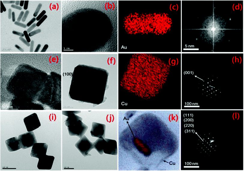
Transmission electron microscopy (TEM) and high-resolution (HRTEM), selected area electron diffraction (SAED), scanning TEM (STEM) and elemental mapping analysis were carried out, with the results presented in Fig. 1. The AuNR size is in the range of 5–50 nm, whereas the thickness of the Cu2O nanocubes (NCs) is in the range of 50–100 nm, and the size of the Au/Cu2O composite is in the range of 50–100 nm. From Fig. 1(a) and (b), the size of the AuNRs ranges between 5 and 50 nm depending on the direction. Fig. 1(c) shows the STEM elemental mapping of Au in the NR structure, which confirms that Au is present in the nanoparticles. The SAED pattern in Fig. 1(d) reveals the crystallinity of the atomic arrangements in the AuNRs. Fig. 1(e)–(h) show the TEM, HRTEM, STEM elemental mapping, and SAED pattern analysis results of the Cu2O NCs. Fig. 1(e) shows that the Cu2O NCs have a uniform shape with an edge length of approximately 80 nm. Fig. 1(f) shows a single Cu2O NC that is lying on its (100) face. Fig. 1(g) shows the STEM elemental mapping which confirms the presence of Cu in the Cu2O NCs. Fig. 1(h) shows the SAED pattern, in which the pattern reveals that the crystallographic zone axis is [001] and confirmation of a nanocube structure. In the same order, Fig. 1(i)–(l) demonstrates the microscopic examination, elemental analysis, and crystallinity analysis results of the Au/Cu2O composite. Fig. 1(i) confirms the formation of a homogeneous NR core–shell structure. The sizes of the Au core and Cu2O shell are approximately 100 nm, respectively. The average size of the pure AuNR is smaller than the Cu2O shell in the composite of Au/Cu2O. It can be observed that there is contrast between dark (Au) and lighter (Cu2O) regions, identifying the formation of the Au/Cu2O composite and further corroborating the elemental mapping in Fig. 1(k). The SAED pattern of the Au/Cu2O composite is shown in Fig. 1(l), which confirms that the Cu2O core–shell is polycrystalline in nature. The energy-dispersive X-ray spectroscopy (EDX) analysis results for Cu, Au, and O are additionally provided in Fig. S1.† The bright-field image of the composite confirms that the Cu2O NCs are covered with Au NPs, making up the core–shell structure. The as-prepared nanocomposite is interconnected in a homogeneous way so that low resistance during electrolyte diffusion is expected but fast ion and electron transport for faradaic reaction also occur.202.2 Optical and BET analysis
The UV-vis spectrum of the resultant NPs is shown in Fig. 2(a). The absorption peaks for the Cu2O NCs and Au/Cu2O composite NPs are present at 489 and 508 nm, respectively. The absorption band at 489 nm is recognized as the band-edge absorption of the Cu2O NCs. The absorption of the AuNRs embedded in Cu2O is observed at 508 nm, which is not very intense due to the band-edge absorption of Cu2O. The surface plasmon resonance spectra of gold materials are significantly red-shifted when they are covered by Cu2O.21–23 The Cu2O absorption appearances are differentiated due to their large sizes that cause solid light dispersion. The absorption of the Au/Cu2O composite NPs is more intense than that of Cu2O. The Fourier-transfer infrared spectra of the Cu2O NCs and Au/Cu2O composite NPs are displayed in Fig. 2(b). The distinctive peak of Cu(I)–O observed at 631 cm−1 reveals the structure of the Cu2O NCs. However, after the formation of the Au/Cu2O composite NPs, the intensity of the Au peak reduced and marginally red-shifted the vibrations of Au–O at 583 and 515 cm−1, and these peaks can be attributed to the functional groups of the Au/Cu2O composite NPs. The minor blue-shift in the Cu–O vibration is feasibly a result of a small particle size.24–26 The wide absorption around the peak at 3498 cm−1 is attributed by O–H stretching with its peak at 1621 cm−1 that is usually observed with bending in water molecules. Thus, only peaks for the as-synthesized Au/Cu2O composite were observed.The resultant Cu2O and Au/Cu2O composite NPs were examined by X-ray diffractometry (XRD). Fig. 2(c) shows the XRD peaks of Cu2O and the Au/Cu2O composite NPs. The diffraction peaks can be seamlessly indexed to crystalline cubic cuprous oxide (cuprite) in terms of both position and relative intensity. The peaks at 2θ values of 32.380°, 36.240°, 43.140°, 52.450°, and 64.400° represent the {110}, {100}, {200}, {211}, {311}, and {222} plane directions of the crystalline Cu2O, correspondingly. The XRD pattern of the Au/Cu2O composite NPs reveals diffraction peaks located at 2θ = 33.0°, 36.0°, 42.8°, and 61.1°, which correspond to the {100}, {111}, {200}, and {222} plane directions of the plain cubic-phase Cu2O NCs. The other diffraction peaks located at 36.7°, 42.8°, 64.4°, and 78.1° can be respectively indexed to the {111}, {200}, {220}, and {311} planes of the face-centered cubic structure of the AuNRs. These results indicate that an ultrathin Cu2O shell is formed on the surface of the metallic AuNRs with neither amorphous nor additional phases.27 XPS was used to identify the surface components on the shell. The survey XPS spectrum of the Au/Cu2O composite is presented in Fig. 2(d), which reveals peaks for the Cu2p, O1s, and Au as well as C1s of the Au/Cu2O composite. The presence of C1s and other peaks should be attributed to the residual capping agents on the particle surface. Generally, by using the peak of C1s at 284.8 eV, the binding energies were calibrated to reduce the charge effect of the samples. This suggests that the interfacial surface charge distribution of the Au/Cu2O composite changed and indicates the formation of a charge-transfer complex. This is explicit evidence of the strong interaction between Au and Cu2O. The peak for Cu2p3/2 in the XPS spectrum is at 932.6 eV as depicted in Fig. S2(i).† Cu is in the +1 oxidation state and is synchronized to the oxygen species, with a peak detected at 530.4 eV. The peak at 533.4 eV in the spectrum can be allocated to the oxygen species in the Cu–O bond, as supported by Fig. S2(ii).† The weak Au peaks from the AuNRs present in the ultrathin Cu2O shell are also detected, as can be confirmed from Fig. S2(iii).† The peaks are shifted towards a lower value compared to those of pure gold (4f7/2 84.2 eV and 4f5/2, 87.8 eV).28 This shift appropriately corresponds to negatively charged AuNRs devoid of any chemical bonding with Cu2O. The donor level of Cu2O is almost equal to the Fermi level of Au (5.4 eV). Thus, electron transfer from Cu2O to Au is possible, leading to an increase in the charge density on the surface of the AuNRs.
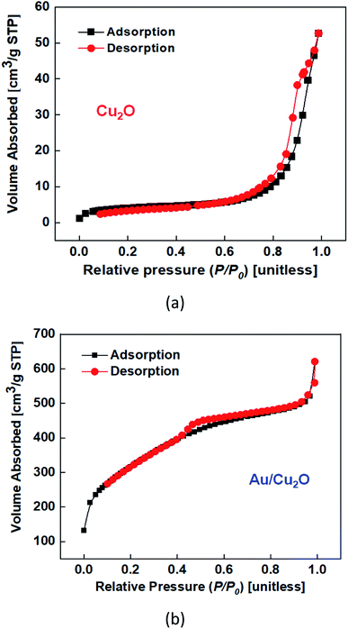
The N2 adsorption isotherms of the Cu2O NCs and Au/Cu2O composite NPs exhibit an analogous type-II curve.29 The Brunauer–Emmett–Teller (BET) effective areas of the Cu2O NC and Au/Cu2O composite NPs were found to be 14.870 m2 g−1 and 1150.760 m2 g−1, respectively, as shown in Fig. 3(a and b). The relative pressure (P/P0) was in the range of 0.45–0.98 and the N2 adsorption/desorption isotherms presented that the Au/Cu2O composite NPs showed the same type-IV curves, indicating a porous structure.30,31 Cu2O has pores with a diameter of 156 nm (Fig. S3(a)†). However, the Au/Cu2O composite has pores with a diameter of 36 nm (Fig. S3(b)†) and a mesoporous network. The main reason for the high surface area is due to the presence of a structural internal surface of pores that are formed during the synthesis process shown in Schematic 1 in the ESI.† Ethanol probably serves as a pore-expanding agent in the synthesis.32 Through combination with the hydrophilic group of the outer layer, ethanol occupies a certain space in the stacked structure. Under the action of combined surfactants, the AuNRs crystallize into smaller grains and aggregate into a highly porous structure, increasing their specific surface area. The results were verified by BET analysis, which indicated that the pore size decreased from 36 to 30 nm, as shown in Fig. S3(b).† The high specific surface area and pore size of the Au/Cu2O composite NPs results in them exhibiting a high specific capacitance. For a superior electrode in an energy device, a high effective surface area of a material usually presents extra active sites, which might eventually contribute towards an improvement in the performance of a supercapacitor. At the same time, the change in mass needs to be considered to contemplate the dramatic increase in the specific surface area, which has the unit of area per mass. Not only the increase in effective area but also the rapid decrease mass leads to a huge specific surface area.
2.3 Formation mechanism of the Au–Cu2O composite NPs
Firstly, pure Cu2O NCs were synthesized via the process detailed in the experimental Section 4.3. The entire synthesis is based on a redox reaction. Cu (OH)42− is initially shaped after adding NaOH to the Cu2O NCs. By altering the reductants and surfactants, diverse CuO nanoparticles of different types can be obtained. In addition to being a reducing agent, L-ascorbic acid also acts as a ligand, coordinating with Cu2+ and forming the cube shell (Au/Cu2O). The Au/Cu2O composite was produced using a combination of CuCl2, sodium dodecyl sulfate (SDS), AuNRs, an aqueous solution of NaOH, and L-ascorbic acid. Identical shape and conformal growth of the Cu2O shells in the cubic structure were obtained. The function of SDS and Cu(OH)42− species can also be understood. When the reducing agent is added to the solution, Cu2+ is reduced to Cu+. The role of ascorbic acid is to link the Cu (OH)42− species with the AuNRs, which promotes the hetero-evolution of Cu2O. Additionally, increasing the volume of the Au nanocrystal solution added to the reaction mixture slowly decreases the size of the Au/Cu2O nanocrystals, and the resultant mixture determines the final nanoparticle size. Size controllability in comparable sizes of Au/Cu2O composites has been achieved using small AuNR cores, via a change in the amount of core Au. The essential redox process can be described using the following equations:| Cu2+ + 2OH− → Cu(OH)2 |
| 2Cu(OH)2 + C6H8O6 → Cu2O + C6H6O6 +3H2O |
In the formation of the Au/Cu2O composite, a solution of AuNRs was used which contains HAuCl4 used as the source material of the Au NRs. Electrostatic interactions may act as the driving force behind the absorption of the metal ions on the surface of Cu2O. Finally, the adsorbed AuCl4 ions were reduced and deposited randomly on the surface of Cu2O by ascorbic acid acting as a reducing agent. Although similar synthetic approaches have been used for Au deposition, the density of the deposited Au NPs was higher herein, presumably due to the higher affinity of AuCl4 for the surface of Cu2O. Hence, strong electrostatic interactions between the positively charged Cu2O and negatively charged AuCl4 are expected, which results in a high density of Au NRs on the Cu2O NC surface. The driving force for Au deposition is very high. Therefore, it is understood well from our findings that ascorbic acid can be used as a reducing agent for the uniform deposition of Au NRs on the Cu2O surface.
3. Electrochemical measurements
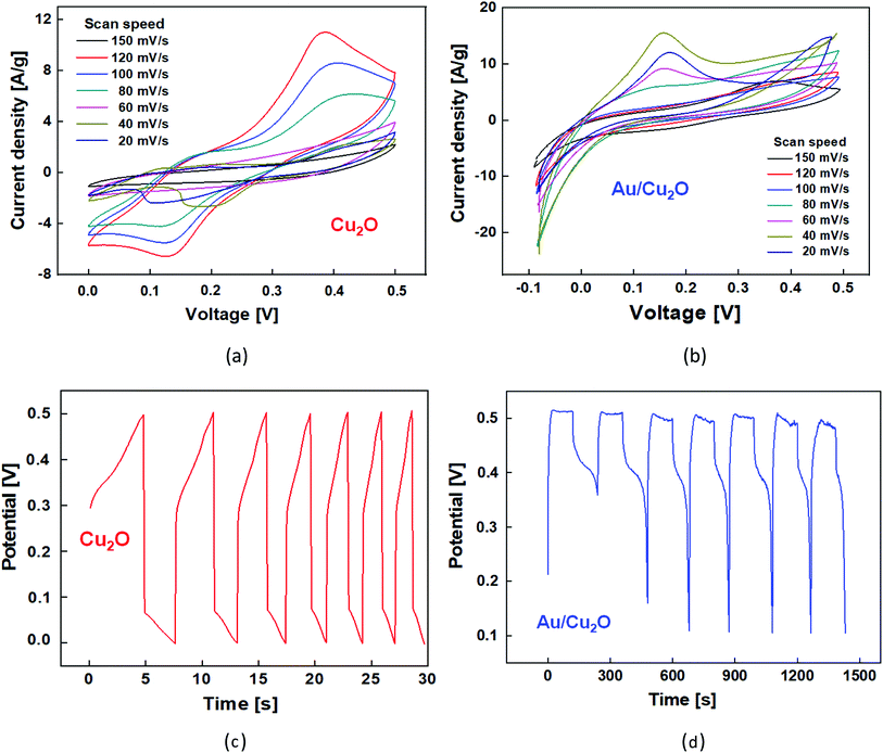
A facile approach was proposed to grow Cu2O and Au/Cu2O composite NPs on the Ni foam substrate followed by an annealing treatment. The Au/Cu2O composite NPs were dropped onto the substrate and vacuum dried at 80 °C for 12 h. The mass of the material was calculated by increasing the areal mass density of the Ni foam after casting the electrode materials and was found to be in the range of 2–4 mg cm−2. In this procedure, commercial Ni foam for the substrate was applied as a current collector. Cleaning was performed using acetone, hydrochloric acid, deionized water, and ethanol in sequence. The Cu wires were attached to the material surface using silver paste to make the electrodes at the same time. The supercapacitor was assembled with a structure of two electrodes separated, which was soaked in an aqueous electrolyte of 2 M KOH solution. Electrochemical measurements of the Cu2O NCs and Au/Cu2O composite NPs were performed in a two-electrode system using 2 M KOH electrolyte. Fig. 4(a) demonstrates the cyclic voltammetry (CV) characteristics of the Cu2O NCs across a voltage sweep between 0 V and 0.8 V at different scan rates in the range of 10–150 mV. The CV curves of Cu2O exhibit pairs of anodic and cathodic peaks with a wide redox background, representing the pseudocapacitive behavior of the material. The pseudocapacitance of the Cu2O is attributed to redox transitions between Cu(I) oxides–Cu(II). The redox reaction for the Cu2O electrode takes place in the following manner:| Cu(I) oxide = Cu(II) oxide + e− | (1) |
At a scan rate of 20 mV s−1, weak redox peaks are observed due to residual oxygen-containing groups. The anodic and cathodic peaks correspond to the oxidation and reduction of metal, resulting in electrochemical reactions that take place, as in the following eqn (2):
| Cu2O + 2OH− ↔ 2CuO + H2O + 2e− | (2) |
As the scan rate increases, the current under the curve gradually rises, which shows that the voltammetry current has a positive relationship with the scan rate. This clearly shows the capacitive behavior of the structure, as can be inferred from the mathematical definition of capacitance, which is the proportional factor between the change in voltage on the capacitor plate and that in the amount of charge, the time integration of the current, on the plate. Also, due to the internal resistance of the electrode and the increase in the scan rate, the current density peak is shifted in performing both forward and subsequent backward sweeps. The capacitive behavior of the Au/Cu2O composite NPs was characterized by carrying out electrochemical measurements at different scan rates from 20 mV s−1 to 150 mV s−1, as shown in Fig. 4(b). It can be observed from the CV that the curve is slightly distorted and that the oxidation peaks are slightly shifted with an increase in the scan rate. Another point noted is that Au can easily be oxidized in less acidic solutions, which was experimentally confirmed by the oxidation peaks becoming more prominent as the scan rate increases. In KOH electrolyte, AuCl2 is simply changed into CuO because of the great bonding affinity between OH− and Cu2+, while Cu2+ remains static on the electrode. The anodic peak (positive current) at 0.1 V signifies an oxidation process associated with Cu+ → Cu2+ (Fig. 4(b)). The peak potentials move to be more anodic with an increase in the scan rate, which is largely associated with internal resistance,33 however, the shift can only be perceived at a relatively low scan rate of <40 mV s−1. Galvanostatic charge–discharge (GCD) measurements were carried out via chronopotentiometry from 0 V to 1.2 V at a current density of 2 A g−1. Fig. 4(c) shows the repeated symmetric triangular shapes observed in the GCD measurements of the Cu2O NCs and Au/Cu2O composite NPs.
The charge/discharge peaks are not on an ideal line since the capacitive operation is subordinate to the faradaic redox reaction. The electrode charging begins to be effective at an applied voltage of higher than 0.1 V owing to the oxidation and discharging process of CuO. This signifies a noble interfacial interaction between the active material and the substrate via a charge/discharge route. Fig. 4(d) shows the GCD analysis results of the Au/Cu2O composite NPs at a current density of 2 A g−1. The peak digresses from the line discharge method of an EDLC. Thus, this shows that there is a significant increase in the effective surface area of the Au/Cu2O composite NPs, which leads to a higher capacitance.
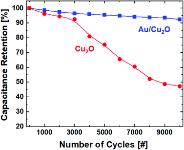
The cycling stability of the Cu2O and Au/Cu2O composite NP composite electrode electrochemical capacitor upon charge/discharge cycles in 2 M KOH at a current density of 2 A g−1 was investigated. Fig. 5 shows the capacitance retention, or, equivalently, the degradation in the specific capacitance (Cs) as a function of the number of cycles. The Au/Cu2O NPs demonstrate a loss in capacitance below 7% even after 10![[thin space (1/6-em)]](https://www.rsc.org/images/entities/char_2009.gif) 000 cycles while the Cu2O NCs show severe degradation of more than 50%. Great electrochemical stability can be expected from the Au/Cu2O composite in supercapacitor applications. The construction of a porous structure over the shell provides conduction pathways for carriers to enter the core. The heterostructure composed of the Au core and porous shell has a large number of electroactive sites. The capacitance is an electrical parameter defined as the change in the amount of charge per that in the applied voltage on the electrodes on both sides of a capacitor. The effective redox processes taking place in the heterostructure have an effect of sustaining the amount of charge over the cyclic operations so that higher stability against degradation in capacitance can be achieved in the capacitor with electrodes made from Au/Cu2O NPs.
000 cycles while the Cu2O NCs show severe degradation of more than 50%. Great electrochemical stability can be expected from the Au/Cu2O composite in supercapacitor applications. The construction of a porous structure over the shell provides conduction pathways for carriers to enter the core. The heterostructure composed of the Au core and porous shell has a large number of electroactive sites. The capacitance is an electrical parameter defined as the change in the amount of charge per that in the applied voltage on the electrodes on both sides of a capacitor. The effective redox processes taking place in the heterostructure have an effect of sustaining the amount of charge over the cyclic operations so that higher stability against degradation in capacitance can be achieved in the capacitor with electrodes made from Au/Cu2O NPs.
Furthermore, the charge transfer at the electrode/electrolyte interface was investigated by electrochemical impedance spectroscopy (EIS) in 2 M KOH aqueous electrolyte with a variation in the frequency from 10 MHz to 100 kHz along with the measurement of the electrical conductivity. Fig. 6 shows the Nyquist plots of the EIS spectra of the Cu2O NCs and Au/Cu2O composite NPs. A semicircle trajectory is depicted across the high-frequency region and a straight line can be observed in the low-frequency region of the data. The semicircle corresponds to the electron transfer resistance, which is responsible for the electron transfer kinetics of the redox Cu2+ and Au2+/Cu3+ links at the electrode interface, whereas the linear trajectory in the low-frequency region signifies general capacitive behavior. The semicircle of the Au/Cu2O composite NPs in the high-frequency region is smaller than that of the Cu2O NCs, representing reduced charge-transfer resistance, whereas the slant of the line for the Au/Cu2O composite NPs is greater than that of the Cu2O NCs, signifying the higher capacitive nature and a lower diffusion resistance of ions in the composite.34,35 Therefore, the Au/Cu2O composite NPs have much lower charge transfer resistance and ion diffusion resistance than the Cu2O NCs, leading to higher reactivity and faster reaction kinetics. The line of the Au/Cu2O composite NPs in the low-frequency region appears to be sharp, which reveals fast diffusion and relocation of the electrolyte ions. In terms of the oxygen content in the active Au/Cu2O composite, that of the NPs is higher than that of the Cu2O NCs; the EIS at the electrode/electrolyte interface is noticeably reduced from 2.2 Ω to 0.65 Ω, correspondingly.36,37 The lower resistance of the Au/Cu2O composite NP electrode makes it presumably more conductive, which can be attributed to a higher effective surface area on which there are more active sites for faradaic reactions and electrolyte penetration to take place. Therefore, Au/Cu2O is more suited for supercapacitor applications due to its high capacitance. The specific capacitance (Cs) [F g−1] of the electrodes can be calculated using eqn (3):
| Cs = (IΔt)/(mΔV) | (3) |
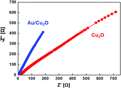 | ||
| Fig. 6 Electrochemical impedance spectra of the Cu2O NCs and Au/Cu2O composite NPs in a frequency range from 10 MHz to 100 kHz. | ||
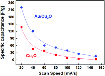 | ||
| Fig. 7 Average specific capacitance (Cs) of the Cu2O NCs and Au/Cu2O composite NPs at different scan rates. | ||
4. Experimental
4.1 Materials and reagents
All the chemicals were of analytical grade and used without purification. Gold(III) chloride trihydrate (HAuCl4·3H2O 99.9%), cetyltrimethylammonium bromide (CTAB 99%), D-glucosamine, silver nitrate (AgNO3 99.9%), copper(II) chloride (CuCl2), sodium borohydride (NaBH4 99%), L-ascorbic acid (AA 99.8+%), copper(II) nitrate hemi-pentahydrate (2Cu(NO3)2·5H2O), and ethanol were obtained from Sigma Aldrich Korea. Sodium hydroxide (98.9+%) and L-glutamic acid were purchased from Dae-Jung Chemical. All of the experiments were conducted in purified water with 18 mQ resistance.4.2 Synthesis of the AuNRs
AuNRs were prepared using a typical seed-mediated growth approach following a modified literature preparation.20 Firstly, a seed mixture was made by adding 0.45 mL of HAuCl4·3H2O (0.01 M) to 8.57 mL of CTAB (0.1 M) solvent, and then to this mixture, 0.7 mL of freshly prepared cold sodium borohydride (0.01 M) solution was rapidly added under magnetic stirring for 15 min. The color of the resultant mixture changed to a light brownish one. The mixture was then left to stand for 5 h to complete the formation of the seed mixture. Furthermore, 100 mL of growth solution was prepared by adding 5 mL of HAuCl4·3H2O (0.01 M) and 95 mL of CTAB (0.1 M) solution. 0.6 mL of 0.01 M AgNO3 solution was added to the mixture under stirring to control the outgrowth of AuNRs. Then, 0.65 mL of L-ascorbic acid (0.1 M) was added in a dropwise manner and the resulting mixture turned colorless. 140 μL of the seed-mediated mixture was then added to the growth mixture. The growth solution slowly transformed into a light blue color over 10 min. The resultant solution was left overnight for maximal growth. Finally, the mixture was centrifuged at a speed of 13![[thin space (1/6-em)]](https://www.rsc.org/images/entities/char_2009.gif) 000 revolutions per minute (rpm) for 20 min.
000 revolutions per minute (rpm) for 20 min.
4.3 Synthesis of the Cu2O NCs
Cu2O NCs were synthesized via the reduction of copper nitrate with L-ascorbic acid following a modified literature protocol.18 0.003 M Cu(NO3)2·5H2O was liquefied in 90 mL of double-distilled ultrapure water. Afterward, 0.4 M sodium hydroxide solutions were prepared in different vials. 0.05 M L-ascorbic acid solution was also prepared in 10 mL of water. Copper nitrate solution was stirred for 15 min and its light blue color turned into dusky blue after adding sodium hydroxide solution. Finally, a cherry-red colored mixture was observed, and, subsequently, the dropwise addition of L-ascorbic acid and stirring for 30 min led to the final solution color turning to bright yellow, confirming the formation of the Cu2O NCs, as supported by the EDX analysis shown in Fig. S1.† The obtained solution was purified repeatedly using ethanol and water after aging for 20 min and kept overnight under a vacuum pump to obtain a completely dry powder.4.4 Synthesis of the Au/Cu2O NPs
The Au/Cu2O composite NPs were synthesized in aqueous solution. 0.125 g of SDS was mixed in 80 mL of 0.004 M CuCl2, then 5.0 mL of the AuNR solution was added into the above mixture in a dropwise manner. Afterward, 10 mL of 0.4 M sodium hydroxide solution was slowly added to it and rapidly stirred at room temperature for 15 min. Subsequently, 10 mL of 0.04 M ascorbic acid solution was added dropwise. The color transformed from blue to yellowish-green, evidence of the formation of the Au/CuO2 NPs. Finally, the mixture was centrifuged at 5000 rpm in water and ethanol three times, respectively, before being subjected to 45 min of aging. The precipitate was re-dispersed in ethanol for additional use. The synthesis procedures were completed using Au/Cu2O composite NPs with a final weight ratio of 4.1 between Au and Cu2O.5. Conclusions
The chemical synthesis of the Cu2O NCs and Au/Cu2O composite NPs featuring an AuNR core and Cu2O shell is herein reported. From the TEM and XRD analysis results, it was confirmed that the as-synthesized material contains AuNRs in the core and Cu2O as the shell and that both materials are highly crystalline. The Au/Cu2O NPs exhibit a core–shell structure in which the AuNRs are embedded as the core surrounded by a Cu2O cubic shell. It is understood that the mass of Au added in the synthesis route plays a major role in controlling the NP size, resulting in Au/Cu2O NPs with different shell thicknesses being obtained as a result. More significantly, the Au/Cu2O composite NPs are crystalline, with a high specific surface area of 1150.760 m2 g−1. Furthermore, these nanoscale architectures were used in a device towards application as a supercapacitor. The Au/Cu2O composite NPs exhibit a high specific capacitance of 235 F g−1 at a current density of 2 A g−1 in 2 M aqueous KOH electrolyte, which is greater than that of Cu2O, at 140 F g−1. It has thus been confirmed that the Au/Cu2O composite is a promising electrode material for use in high-performance supercapacitors.Conflicts of interest
There are no conflicts to declare.Acknowledgements
This work was supported by the National Research Foundation of Korea (NRF) through a Research Grant funded by the Korean Ministry of Science and ICT (MSIT) under the Grant No. 2021M3H4A6A01048300.References
- M. Li, J. Cheng, J. Wang, F. Liu and X. Zhang, Electrochim. Acta, 2016, 206, 108–115 CrossRef CAS.
- J. Suntivich, H. A. Gasteiger, N. Yabuuchi and Y. Shao-Horn, J. Electrochem. Soc., 2010, 157, B1263–B1268 CrossRef CAS.
- X. Wang, X. Han, M. Lim, N. Singh, C. L. Gan, M. Jan and P. S. Lee, J. Phys. Chem. C, 2012, 116, 12448–12454 CrossRef CAS.
- A. K. Singh, D. Sarkar, K. Karmakar, K. Mandal and G. Khan, ACS Appl. Mater. Interfaces, 2016, 8, 20786–20792 CrossRef CAS PubMed.
- C. Lamiel and J. J. Shim, New J. Chem., 2016, 40, 4810–4817 RSC.
- S. Wang, L. Jiang, L. Hu, Q. Wang, S. Zhan and Y. Lu, J. Alloys Compd., 2020, 815, 1520105 Search PubMed.
- J. Yan, Z. Fan, T. Wei, W. Qian, M. Zhang and F. Wei, Carbon, 2010, 48, 3825–3833 CrossRef CAS.
- V. Subramanian, H. Zhu and B. Wei, J. Power Sources, 2006, 159, 361–364 CrossRef CAS.
- H. Zang, Y. Tian, S. Wang, Y. Huang, J. Wen, C. Hang and C. Wang, Chem. Eng. J., 2020, 399, 125–175 Search PubMed.
- X. Du, C. Wang, M. Chen, Y. Jiao and J. Wang, J. Phys. Chem. C, 2009, 113, 2643–2646 CrossRef CAS.
- S. Z. Golkhatmi, M. Khalaj, A. Izaspanahi and A. Sedghi, Solid State Sci., 2015, 106, 1060336 Search PubMed.
- K. K. Purushothaman, B. Saravanakumar, I. M Babu, B. Sethuraman and G. Muralidharan, RSC Adv., 2014, 4, 23485–23491 RSC.
- I. Y. Bu and R. Huang, Ceram. Int., 2016, 43, 45–50 CrossRef.
- A. Pendashteh, M. S. Rahmanifar and M. F. Mousavi, Ultrason. Sonochem., 2014, 21, 643–652 CrossRef CAS PubMed.
- J. F. Juni, S. R Majid, S. N. F. Yusuf and Z. Osman, Microchem. J., 2021, 164, 106–155 CrossRef.
- H. Zhou, G. Han, Y. Xiao, Y. Chang and H. J. Zhai, J. Power Sources, 2014, 263, 259–267 CrossRef CAS.
- C. Chaojing, L. Aifeng, L. Yanei, M. Jingbo, Z. Xiaoliang and C. Hongwei, Mater. Lett., 2017, 196, 308–311 CrossRef.
- M. Yu, Y. Ma, J. Liu and S. Li, Carbon, 2015, 87, 98–105 CrossRef CAS.
- Q. Cheng, J. Tang, J. Ma, H. Zhang, N. Shinya and L. C. Qin, J. Phys. Chem. C, 2011, 115, 23584–23590 CrossRef CAS.
- M. H. Bai, T. Y Liu, F. Luan, Y. Li and X. X. Liu, J. Mater. Chem. A, 2014, 2, 10882–10888 RSC.
- X. Zheng, L. Miao, Z. Song, W. Du, D. Zhu, Y. Lv, L. Li, L. Gan and M. Liu, J. Mater. Chem. A, 2022, 10, 611–621 RSC.
- D. P. Dubal, S. H. Lee, J. G. Kim, W. B. Kim and C. D. Lokhande, J. Mater. Chem., 2012, 22, 3044–3052 RSC.
- K. Shi, X. Pang and I. Zhitomirsky, J. Mater. Sci. Technol., 2020, 55, 182–189 CrossRef.
- C. Pirvu, C. C. Manole, A. B. Stoian and I. Demetrescu, Electrochim. Acta, 2011, 56, 9893–9903 CrossRef CAS.
- K. Shi and I. Zhitomirsky, J. Power Sources, 2013, 240, 42–49 CrossRef CAS.
- K. K. Sourav, R. Debdhutta and C. R. Somnath, J. Alloys Compd., 2022, 895, 1620546 Search PubMed.
- Z. Song, L. Miao, L. Ruhimann, Y. Lv, D. Zhu, L. Li, L. Gan and M. Liu, Adv. Mater., 2021, 33, 2104148 CrossRef CAS PubMed.
- K. Mukesh, C. Himani, S. Biswarup and D. Sasanka, Z. Phys. Chem., 2019, 233, 85–104 Search PubMed.
- S. Shahrokhian, Z. Kamalzadeh and R. S. Saberi, Electroanal, 2011, 23, 2925–2934 CrossRef CAS.
- Y. Song, T. Y. Liu, X. X. Xu, D. Y. Feng, Y. Li and X. X. Liu, Adv. Funct. Mater., 2015, 25, 4626–4632 CrossRef CAS.
- G. Mitchell, F. Davis and C. Legge, Synth. Met., 1988, 26, 247–257 CrossRef CAS.
- Y. Jiang, J. Chen, X. Zhao and G. Ma, Catalysts, 2021, 11, 600 CrossRef CAS.
- J. Chen, H. Liu, X. Wan, X. Xue, Y. Zhang, Y. Liu and A. Yuan, J. Nanopart. Res., 2019, 21, 1–10 CrossRef.
- T. Liu, L. Finn, M. Yu, H. Wang, T. Zhai, X. Lu, Y. Tong and Y. Li, Nano Lett., 2014, 14, 2522–2527 CrossRef CAS PubMed.
- C. Yang, L. Zhang, N. Hu, Z. Yang, H. Wei and Y. Zhang, J. Power Sources, 2016, 302, 39–45 CrossRef CAS.
- S. Lyu, H. Chang, F. Fu, L. Hu, J. Huang and S. Wang, J. Power Sources, 2016, 327, 438–446 CrossRef CAS.
- M. Shoeb, M. Mobin, S. M. Adan, I. F. Ansari, M. N. Khan, S. Zaidi and M. Y. Ansari, Surf. Interfaces, 2022, 28, 101650 CrossRef.
- Z. Zhou, L. Miao, H. Duan, Z. Wang, Y. Lv, W. Xiong, D. Zhu, L. Li, M. Liu and L. Gan, Chin. Chem. Lett., 2020, 31, 1226–1230 CrossRef CAS.
Footnote |
| † Electronic supplementary information (ESI) available. See DOI: 10.1039/d2ra00812b |
| This journal is © The Royal Society of Chemistry 2022 |

