 Open Access Article
Influence of hydroquinone content on thermotropic liquid crystalline copolymers and nanocomposites: thermo-mechanical properties and morphology†
Hyeonjun Wooa,
Hara Jeonb,
Du Chan Jangb,
Lee Ku Kwacbc,
Hong Gun Kimbc and
Jin-Hae Chang *c
*c
aDepartment of Polymer Science and Engineering, Kumoh National Institute of Technology, Gumi 39177, Korea
bGraduate School of Carbon Convergence Engineering, Jeonju University, Jeonju 55069, Korea
cInstitute of Carbon Technology, Jeonju University, Jeonju 55069, Korea. E-mail: jhchang@jj.ac.kr
First published on 22nd March 2022
Abstract
Thermotropic liquid crystalline copolyesters (Co-TLCPs) were synthesized by varying the hydroquinone (HQ) molar ratio from 1–5 with respect to the 2,5-diethoxyterephthalic acid (ETA) monomer. The thermal properties and liquid crystalline mesophases of the synthesized Co-TLCP were investigated. All of the Co-TLCPs synthesized using a HQ molar ratio of 1–5 showed a nematic liquid crystalline phase. Among the Co-TLCPs obtained using HQ in various molar ratios, the most stable physical properties and a clear liquid crystalline phase were obtained when HQ was 4 mol. Among the various Co-TLCPs synthesized, hybrids were prepared using Co-TLCP synthesized with a 1![[thin space (1/6-em)]](https://www.rsc.org/images/entities/char_2009.gif) :
:![[thin space (1/6-em)]](https://www.rsc.org/images/entities/char_2009.gif) 4 = ETA
4 = ETA![[thin space (1/6-em)]](https://www.rsc.org/images/entities/char_2009.gif) :
:![[thin space (1/6-em)]](https://www.rsc.org/images/entities/char_2009.gif) HQ ratio and organoclay. A 1–10% loading of the organoclay Cloisite 93A was employed per weight of TLCP, and the clay was dispersed using the melt intercalation method. Among the Co-TLCP hybrids, the morphology and thermal properties of the hybrids were investigated according to the changes in the Cloisite 93A in the 1–10 wt% range. In general, the thermal properties were superior when the organoclay loading was 3 wt% and were inferior when the organoclay amount was 5 wt% or more. This result was confirmed by the dispersibility of the clay through transmission electron microscopy.
HQ ratio and organoclay. A 1–10% loading of the organoclay Cloisite 93A was employed per weight of TLCP, and the clay was dispersed using the melt intercalation method. Among the Co-TLCP hybrids, the morphology and thermal properties of the hybrids were investigated according to the changes in the Cloisite 93A in the 1–10 wt% range. In general, the thermal properties were superior when the organoclay loading was 3 wt% and were inferior when the organoclay amount was 5 wt% or more. This result was confirmed by the dispersibility of the clay through transmission electron microscopy.
1. Introduction
Thermotropic liquid crystalline polyesters (TLCPs) have superior thermo-mechanical properties compared to other polymers because of their excellent dimensional stability, heat resistance, and molecular orientation during processing.1–3 However, the limitations of TLCP include the difficulties in processing, high processing temperatures, and inadequate shear properties.4 For example, a wholly aromatic TLCP containing a mesogen and possessing a straight and rigid rod structure with an aromatic structure has very good thermo-mechanical properties. However, its high melting point not only makes the processing difficult, but also causes poor solubility in common solvents, which is a disadvantage.5,6Mesogenic units exhibiting TLCP properties generally contain two or three aromatic (or cyclo-aliphatic) rings linked at the para-position by ester bonds to maintain the aromatic rings straight. These mesogenic structures were mainly synthesized using terephthalic acid, p-hydroxybenzoic acid (HBA), naphthalenedicarboxylic acid, hydroquinone (HQ), and p,p′-biphenol in their unsubstituted or substituted forms.7–10 However, TLCPs containing straight aromatic and aliphatic units can form mesogenic groups arranged in a regular manner by employing flexible aliphatic segments of different lengths.11,12
By the introduction of a flexible alkyl group into the rigid main chain, the melting point can be lowered, the solubility of the polymer can be increased, and the compatibility between the matrix polymer and the additive can be increased when used as a composite material.13–15 Therefore, despite the slightly inferior physicochemical properties, improvements in the applicability in several areas may be achieved by increasing the compatibility by using the intermolecular attraction of the chain by employing the alkyl group. Fillers such as elastomers, clays, or glass fibers have long been added as reinforcing fibers for improving the physical properties of TLCP.16 However, such fillers have poor miscibility or compatibility, increase the viscosity in the molten state, render the uniform dispersion of the reinforcing fibers difficult, and cause wear of the processing equipment, particularly, during processing. In addition, increase in temperature is known to cause unexpected chemical reactions owing to thermal decomposition.
Clay is a nano-sized filler. It has an interlayer length/width ratio (aspect ratio) of approximately 200–2000.17,18 While its hydrophilic properties render it incompatible with lipophilic polymers, use of organoclay synthesized using a suitable organic agent allows formation of nanometer (nm)-sized particles upon dispersion of the clay in the polymer. Further, uniform dispersion of the filler in the matrix polymer at the nanoscale improves the various properties of the hybrid material obtained in the nano size.19,20 Among the methods for synthesizing hybrid materials using organoclay,21–23 the in situ intercalation method involves dispersing the filler in its monomer state, and the solution intercalation method uses the filler as a solution in a solvent. Melt intercalation is another method which involves melting the filler above its melting point. Among these, the melt intercalation method is advantageous owing to its simplicity and feasibility for mass production at low cost owing to the dispersion above the melting point.
Bulk and melt polycondensation are the most commonly used commercial synthetic methods for the large-scale production of TLCP.24–26 Acetylated hydroxyl compounds and free carboxylic acids are the typical monomers used in TLCP melt polycondensation.27 Alternatively, feeding mixtures of diol(s) and dicarboxylic acid(s) together into the reactor with an excess of acetic anhydride is another approach, wherein, the mixtures are allowed to mix well in an inert and dry atmosphere and simultaneously heated by increasing the temperature in a step-wise fashion. The removal of acetic acid was accompanied by a gradual increase of the melt viscosity and the mixture turned opaque because polycondensation led to a progressive increase in the molecular weight and formation of an LC melt. At the end of the polycondensation, the low-molecular-weight compounds were removed under vacuum. Solid-state polymerization was carried out in an inert atmosphere and under reduced pressure at a temperature approximately 10–30 °C below the original melting point to obtain the desired increase of the molecular weight of the polymer.28
In this study, various thermotropic liquid crystalline copolyesters (Co-TLCPs) containing a dialkoxy group in the side group were synthesized. Lowering of the Co-TLCP melting point and processability improvements were simultaneously achieved by using this alkyl group. 2,5-Diethoxyterephthalic acid (ETA) and HQ, obtained by using several reaction steps, were used as monomers for synthesizing Co-TLCP, and several Co-TLCPs were synthesized by varying the HQ molar ratios (1–5 moles). Hybrid Co-TLCPs were synthesized by using Cloisite 93A as an organoclay in Co-TLCP containing 4 moles of HQ. Hybrids were prepared using 0–10 wt% of the organoclay.
The purpose of this study is the investigation of the physical properties of various Co-TLCPs synthesized by reacting the ETA containing an alkoxy group with various contents of HQ. In addition, we attempted to prepare hybrids by adding various amounts of organoclay to the Co-TLCP matrix, and to investigate how the dispersed nano-sized clay affects the thermal properties, morphology, and liquid crystalline mesophase change of the hybrid. In addition, we suggest the application potential of various hybrids by using the change in physical properties according to the dispersion of clay in the Co-TLCP matrix.
2. Experimental method
2.1. Materials
The diethyl-2,5-dihydroxyterephthalate monomer used for Co-TLCP synthesis was purchased from Sigma Aldrich Chemical Co. (Yongin, Korea). HQ, acetic anhydride, and bromoethane were purchased from TCI Co. (Seoul, Korea). N,N-Dimethylformamide (DMF) and hydrochloric acid (HCl), used as solvents, were purchased from Daejing Co. (Seoul, Korea).2.2. Monomer synthesis
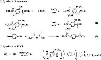
2,5-Diethoxyterephthalic acid (monomer 1) was synthesized using multi-step synthesis methods.29 HQ was reacted with acetic anhydride to synthesize acetoxy-HQ (monomer 2). The synthesis of the monomers is shown in Scheme 1.2.3. Synthesis of Co-TLCP
Co-TLCP was polymerized using the synthesized monomer via melt polymerization. Because the method for synthesizing Co-TLCP is almost similar to the ones used for the others, the procedure for Co-TLCP alone, in a ETA![[thin space (1/6-em)]](https://www.rsc.org/images/entities/char_2009.gif) :
:![[thin space (1/6-em)]](https://www.rsc.org/images/entities/char_2009.gif) HQ molar ratio of 1
HQ molar ratio of 1![[thin space (1/6-em)]](https://www.rsc.org/images/entities/char_2009.gif) :
:![[thin space (1/6-em)]](https://www.rsc.org/images/entities/char_2009.gif) 4, will be given as an example (see Fig. 1): 8 g (3.15 × 10⁻² mole) of ETA and 24.04 g (1.26 × 10⁻¹ mole) of acetoxy-HQ were placed in a polymerization tube and heated under a uniform nitrogen stream while increasing the temperature. Because acetic acid, a reaction by-product, was continuously generated during the heating process, polymerization was completed by maintaining a vacuum of 1 Torr to increase the molecular weight. The molar ratios and temperature conditions of the various monomer contents for synthesizing Co-TLCP are summarized in Table 1. The product obtained in solid form was cooled to room temperature, and the product in the powder form was purified using a Soxhlet extractor with acetone for 72 h to remove the unreacted monomers. The purified TLCP was obtained by drying in a vacuum oven for 24 h at 60 °C. The inherent viscosities of Co-TLCPs, measured at a concentration of 0.1 g dL−1 using a solvent mixture of phenol/p-chlorophenol/tetrachloroethane in a 25/40/35 (w/w/w) ratio at 25 °C, ranged from 1.50–1.94 (see Table 2).
4, will be given as an example (see Fig. 1): 8 g (3.15 × 10⁻² mole) of ETA and 24.04 g (1.26 × 10⁻¹ mole) of acetoxy-HQ were placed in a polymerization tube and heated under a uniform nitrogen stream while increasing the temperature. Because acetic acid, a reaction by-product, was continuously generated during the heating process, polymerization was completed by maintaining a vacuum of 1 Torr to increase the molecular weight. The molar ratios and temperature conditions of the various monomer contents for synthesizing Co-TLCP are summarized in Table 1. The product obtained in solid form was cooled to room temperature, and the product in the powder form was purified using a Soxhlet extractor with acetone for 72 h to remove the unreacted monomers. The purified TLCP was obtained by drying in a vacuum oven for 24 h at 60 °C. The inherent viscosities of Co-TLCPs, measured at a concentration of 0.1 g dL−1 using a solvent mixture of phenol/p-chlorophenol/tetrachloroethane in a 25/40/35 (w/w/w) ratio at 25 °C, ranged from 1.50–1.94 (see Table 2).
| HQa in TLCP (mole ratio) | Temperature,°C/time, min/pressure, torr |
|---|---|
| a Hydroquinone. | |
| 1 | 240/120/760 → 260/60/760 → 280/60/760 → 285/60/760 → 285/30/300 → 285/60/1 |
| 2 | 240/60/760 → 260/90/760 → 280/120/760 → 285/60/300 → 290/60/1 |
| 3 | 240/60/760 → 260/90/760 → 280/120/760 → 285/60/760 → 285/30/300 → 285/60/1 |
| 4 | 240/60/760 → 260/90/760 → 280/60/760 → 285/60/300 → 290/30/1 |
| 5 | 240/60/760 → 260/90/760 → 280/60/760 → 285/60/300 → 290/30/1 |
| HQ in TLCP (mole ratio) | IVa | Tg (°C) | Tm (°C) | ΔHm (J g−1) | Ti (°C) | ΔHi (J g−1) | TiDb (°C) | wtR600c (%) | LC phase | DCd (%) |
|---|---|---|---|---|---|---|---|---|---|---|
| a Inherent viscosity was measured at a concentration of 0.1 g dL−1 solution in phenol/p-chlorophenol/tetrachloroethane = 25/40/35 (w/w/w) at 25 °C.b At a 2% initial weight-loss temperature.c Weight % of residue at 600 °C.d Degree of crystallinity.e Nematic schlieren texture. | ||||||||||
| 1 | 1.50 | 94 | 148 | 3.43 | 217 | 1.91 | 300 | 31 | Nem.e | 29 |
| 2 | 1.94 | 95 | 147 | 3.15 | 219 | 1.59 | 310 | 29 | Nem. | 30 |
| 3 | 1.89 | 100 | 208 | 1.19 | 258 | 1.06 | 329 | 27 | Nem. | 35 |
| 4 | 1.67 | 103 | 210 | 0.31 | 259 | 7.35 | 340 | 29 | Nem. | 40 |
| 5 | 1.84 | 108 | — | — | 269 | 2.52 | 352 | 30 | Nem. | 36 |
2.4. Preparation of Co-TLCP hybrids
The organoclay used in this experiment was Cloisite 93A. Co-TLCP, synthesized in a 1![[thin space (1/6-em)]](https://www.rsc.org/images/entities/char_2009.gif) :
:![[thin space (1/6-em)]](https://www.rsc.org/images/entities/char_2009.gif) 4 = ETA
4 = ETA![[thin space (1/6-em)]](https://www.rsc.org/images/entities/char_2009.gif) :
:![[thin space (1/6-em)]](https://www.rsc.org/images/entities/char_2009.gif) HQ molar ratio, was used as the matrix. All samples were dispersed by the melt intercalation method under the same conditions, and organoclay was used in various amounts (1–10 wt%) with respect to the matrix. Because the synthesis method for all Co-TLCP hybrids according to the content of organoclay was the same, manufacturing process of the hybrid containing 3 wt% of Cloisite 93A alone is described here. The moisture from Cloisite 93A and the Co-TLCP was removed by drying at 60 °C for 24 h. At 260 °C, where Co-TLCP can be melted and the organoclay is stable, 29.1 g of Co-TLCP and 0.90 g of Cloisite 93A were placed in a polymerization tube and dispersed under a nitrogen stream. A dispersed hybrid was obtained by vigorous stirring for 1 h. The product was cooled to room temperature and finally obtained as a powder.
HQ molar ratio, was used as the matrix. All samples were dispersed by the melt intercalation method under the same conditions, and organoclay was used in various amounts (1–10 wt%) with respect to the matrix. Because the synthesis method for all Co-TLCP hybrids according to the content of organoclay was the same, manufacturing process of the hybrid containing 3 wt% of Cloisite 93A alone is described here. The moisture from Cloisite 93A and the Co-TLCP was removed by drying at 60 °C for 24 h. At 260 °C, where Co-TLCP can be melted and the organoclay is stable, 29.1 g of Co-TLCP and 0.90 g of Cloisite 93A were placed in a polymerization tube and dispersed under a nitrogen stream. A dispersed hybrid was obtained by vigorous stirring for 1 h. The product was cooled to room temperature and finally obtained as a powder.
2.5. Characterization
The structure of the synthesized Co-TLCP was confirmed using Fourier-transform infrared (FT-IR) spectroscopy (Bruker VERTEX 80v, Berlin, Germany) and carbon-13 nuclear magnetic resonance (13C-NMR) spectroscopy (Bruker 400 DSX NMR, Berlin, Germany). 13C cross-polarization (CP)/magic angle spinning (MAS) NMR experiments were performed at a Larmor frequency of 100.61 MHz, and an MAS rate of 12 kHz to minimize the rotating sidebands. Tetramethylsilane (TMS) was used to standardize the NMR spectra.To investigate the thermal properties of Co-TLCPs and their hybrids, a differential scanning calorimeter (DSC) (DuPont 910, New Castle, DE, USA), and a thermogravimetric analyzer (TGA) (Auto-TGA 1000, New Castle, DE, USA) from TA Instruments were used. The measurements were carried out under a nitrogen stream, by increasing the temperature at a rate of 20 °C min−1. The wide-angle X-ray diffraction (XRD) was measured using a D-MAX2500-PC (Tokyo, Japan) model of Rigaku Corporation equipped with a Ni-filter using a Cu-Kα target. The 2θ value was measured at room temperature at a rate of 2° min−1 within the 2–35° range.
Polarized optical microscopy (POM) with a hot stage was used to observe the liquid crystalline phase change behavior by increasing the temperature using a Ortholux (Leitz, Berlin, Germany). The clay dispersed in the film on the Co-TLCP hybrid was observed using a transmission electron microscope (TEM, JEOL, JEM 2100, Tokyo, Japan). Specimens were prepared by curing in an epoxy resin at 70 °C for 24 h, and samples with a thickness of 90 nm were prepared using a microtome equipped with a glass knife in vacuum. The TEM acceleration voltage was 120 kV.
3. Results and discussion
3.1. Co-TLCP analysis by FT-IR and 13C-NMR
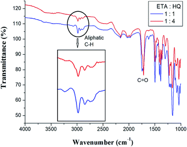
Co-TLCPs were synthesized by varying the HQ molar ratios, and the structures of all Co-TLCPs were confirmed by FT-IR.30 The spectral result for the Co-TLCP prepared with a 1![[thin space (1/6-em)]](https://www.rsc.org/images/entities/char_2009.gif) :
:![[thin space (1/6-em)]](https://www.rsc.org/images/entities/char_2009.gif) 4 = ETA
4 = ETA![[thin space (1/6-em)]](https://www.rsc.org/images/entities/char_2009.gif) :
:![[thin space (1/6-em)]](https://www.rsc.org/images/entities/char_2009.gif) HQ molar ratio is as follows. The C
HQ molar ratio is as follows. The C![[double bond, length as m-dash]](https://www.rsc.org/images/entities/char_e001.gif) O stretching peak of the ester at 1724 cm−1 and that of the alkyl group at 2980 cm−1 were observed. The spectral results of Co-TLCP prepared according to different HQ molar ratios are shown in Fig. 1. Compared to when the ETA
O stretching peak of the ester at 1724 cm−1 and that of the alkyl group at 2980 cm−1 were observed. The spectral results of Co-TLCP prepared according to different HQ molar ratios are shown in Fig. 1. Compared to when the ETA![[thin space (1/6-em)]](https://www.rsc.org/images/entities/char_2009.gif) :
:![[thin space (1/6-em)]](https://www.rsc.org/images/entities/char_2009.gif) HQ molar ratio is 1
HQ molar ratio is 1![[thin space (1/6-em)]](https://www.rsc.org/images/entities/char_2009.gif) :
:![[thin space (1/6-em)]](https://www.rsc.org/images/entities/char_2009.gif) 1, when the molar ratio is 1
1, when the molar ratio is 1![[thin space (1/6-em)]](https://www.rsc.org/images/entities/char_2009.gif) :
:![[thin space (1/6-em)]](https://www.rsc.org/images/entities/char_2009.gif) 4, the intensity of the aliphatic C–H peak and its area are relatively small. This is because, when the molar ratio of HQ is increased to 4, the aliphatic C–H component of the ETA component is relatively decreased.
4, the intensity of the aliphatic C–H peak and its area are relatively small. This is because, when the molar ratio of HQ is increased to 4, the aliphatic C–H component of the ETA component is relatively decreased.
Solid 13C CP/MAS at room temperature was used for a more accurate Co-TLCP structure analysis.30 The 13C chemical shift of the Co-TLCP prepared with a 1![[thin space (1/6-em)]](https://www.rsc.org/images/entities/char_2009.gif) :
:![[thin space (1/6-em)]](https://www.rsc.org/images/entities/char_2009.gif) 4 = ETA
4 = ETA![[thin space (1/6-em)]](https://www.rsc.org/images/entities/char_2009.gif) :
:![[thin space (1/6-em)]](https://www.rsc.org/images/entities/char_2009.gif) HQ molar ratio was obtained for the carbons of the alkoxy groups and aromatic rings. The 13C chemical shifts for CH3 and CH2 of the alkoxy group were recorded at 14.36 and 64.60 ppm, respectively, as shown in Fig. 2. The peaks at 116.23, 122.92, 149.59, and 152.49 ppm are assigned to the benzene rings, and the chemical shift of 164.11 ppm is attributed to the C
HQ molar ratio was obtained for the carbons of the alkoxy groups and aromatic rings. The 13C chemical shifts for CH3 and CH2 of the alkoxy group were recorded at 14.36 and 64.60 ppm, respectively, as shown in Fig. 2. The peaks at 116.23, 122.92, 149.59, and 152.49 ppm are assigned to the benzene rings, and the chemical shift of 164.11 ppm is attributed to the C![[double bond, length as m-dash]](https://www.rsc.org/images/entities/char_e001.gif) O. The peak for the carbon of the C
O. The peak for the carbon of the C![[double bond, length as m-dash]](https://www.rsc.org/images/entities/char_e001.gif) O bonds has a relatively low intensity compared to those of the other peaks. The spinning sidebands for the benzene rings are marked with asterisks. The chemical shifts of all the carbons were consistent with the chemical structure shown in Fig. 2.
O bonds has a relatively low intensity compared to those of the other peaks. The spinning sidebands for the benzene rings are marked with asterisks. The chemical shifts of all the carbons were consistent with the chemical structure shown in Fig. 2.
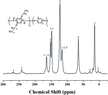 | ||
Fig. 2 13C-NMR chemical shifts of Co-TLCP at room temperature. In the chemical formula, x![[thin space (1/6-em)]](https://www.rsc.org/images/entities/char_2009.gif) : :![[thin space (1/6-em)]](https://www.rsc.org/images/entities/char_2009.gif) y = 1 y = 1![[thin space (1/6-em)]](https://www.rsc.org/images/entities/char_2009.gif) : :![[thin space (1/6-em)]](https://www.rsc.org/images/entities/char_2009.gif) 4. The spinning sidebands are marked with asterisks (*). 4. The spinning sidebands are marked with asterisks (*). | ||
3.2. Thermal behaviors
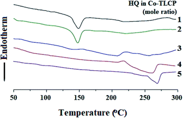
The thermal properties obtained using DSC were all obtained using the secondary heating curve, and the scanning temperature range of the DSC was determined in advance using TGA to prevent thermal decomposition. Table 2 summarizes the DSC results for the Co-TLCPs prepared using the various HQ molar ratios.The glass transition temperature (Tg) of the Co-TLCP was 94 °C when HQ was 1 mol. However, when the HQ component was increased from 2 to 5 mol, the Tg continued to increase from 95 to 108 °C. This observed increase in Tg is because the segmental motion of the polymer chain becomes difficult as the content of the straight and rigid shaped HQ monomer increases. From these results, it was found that the number of moles of HQ is dependent on the segmental motion of the polymer chain.31,32
The melting transition temperature (Tm) of Co-TLCP was affected by the number of moles of HQ, as in Tg. When HQ was 1 mol, the Co-TLCP exhibited a Tm of 148 °C, but as the HQ molar ratio of the copolymer increased from 2 to 4, the Tm value increased significantly from 147 to 210 °C. This result indicates that the straight and rigid rod-shaped HQ improves the overall molecular packing and increases the Tm.33 However, when HQ was 5 mol, Tm was not observed because the excess HQ content interfered with the regularity of the polymer chain and effective molecular packing. Similar to the Tm result, in the case of the enthalpy change (ΔHm) of the crystal-anisotropic transition, ΔHm decreased gradually from 3.43 to 0.31 as the number of moles of HQ increased from 1 to 4 moles, as shown in Table 2.
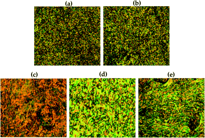
Similar to the results of Tg and Tm, the isotropic transition temperature (Ti) constantly increased according to the number of moles of HQ in Co-TLCP. That is, as the number of moles of HQ increased from 1 to 5, Ti increased constantly from 217 to 269 °C. The enthalpy change (ΔHi) of the anisotropic–isotropic transition showed the highest value (7.35 J g−1) when HQ was increased to 4 mol (Table 2). However, when HQ becomes 5 mol, the liquid crystal state became unstable owing to excessive HQ content, and ΔHi suddenly decreased to 2.52 J g−1. The changes in the thermal properties of the Co-TLCPs according to the molar ratio of various HQs are compared in Fig. 3.
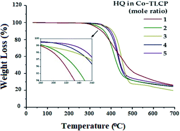
The TGA results according to the number of moles of HQ for the Co-TLCP series are shown in Fig. 4, and the results are summarized in Table 2. When the number of moles of HQ in Co-TLCP was increased from 1 to 4, the initial decomposition temperature (TiD) gradually increased from 300 to 340 °C. When this value was further increased to 5 mol of HQ, the TiD value reached 352 °C. As previously described, HQ can increase the overall thermal stability of Co-TLCP because it is a linear and strong rod-shaped monomer. Therefore, if the structure and ratio of the monomers of the copolymer in the molten state are carefully selected, the deterioration and deformation of the physical properties due to the thermal decomposition during processing can be effectively controlled. For a 1–5 molar ratio of HQ in Co-TLCP, the weight residue at 600 °C (wtR600) was 27–31%. The wtR600 value of the TLCP synthesized in this study is lower than that of most TLCPs with a straight rod-shaped structure because of the low heat-resistance of the diethoxy side group in the main chain.
3.3. Liquid crystalline mesophases
The liquid crystalline mesophase was mainly obtained between Tm and Ti, and the heating and cooling processes were repeated several times to obtain a better texture. In our Co-TLCPs, nematic phases were observed in all liquid crystalline phases obtained regardless of the number of moles of HQ (Table 2). Due to the high molecular weight and difficult flow during heating, perfectly developed textures could not be obtained. Fig. 5 shows pictures of typical schlieren nematic textures obtained at different temperatures for the synthesized TLCP according to the various HQ molar ratios.The stability of the liquid crystalline mesophase shown by TLCP depends on the aspect ratio and stiffness of the monomers.31–34 In general, if the main chain of the polymer is straight and rigid, such as in HQ, the liquid crystalline phase of the copolymer can be stabilized regardless of the number of moles of the HQ monomer. As can be seen in Fig. 5, as the number of moles of HQ increased from 1 to 4, the liquid crystalline phase became clearer and the schlieren nematic texture was clearly observed. However, when the HQ was 5 mol, the thread-like nematic phase was not clear compared to when the HQ was 4 mol. This can be explained by the presence of the excess HQ, as already described in the previous section.
3.4. XRD
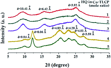
Table 2 shows the degree of crystallinity (DC) of the Co-TLCPs prepared with varied HQ molar ratios. The DC of the Co-TLCP containing the HQ monomer gradually increased from 29 to 40% as the HQ increased from 1 to 4 moles. This increase in DC is due to the rigid rod-shaped HQ, which facilitates molecular packing. However, when HQ became 5 mol, the excess HQ interferes with molecular packing, and the DC reduced to 36%. This phenomenon has already been invoked for explaining the thermal properties.Fig. 6 shows the XRD patterns according to the number of moles of the various HQs in Co-TLCP. Co-TLCP samples containing up to 3 moles of HQ exhibited a similar XRD pattern. However, a completely different pattern was observed when the moles of HQ was greater than 4, and several new peaks were also observed. This result indicates that HQ of 4 is an important factor that influences the crystal structure of Co-TLCP. However, when HQ was 5, the shape of the peak is similar to that when HQ was 4; however, in contrast, the intensity of the peak decreased.
3.5. XRD of Co-TLCP hybrids
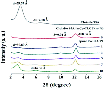
Fig. 7 shows the XRD results of the organoclay, pure Co-TLCP, and Co-TLCP hybrids containing various organoclay contents wherein the 2θ ranged from 2–16°. Intrinsic peaks of organoclay Cloisite 93A were observed with a strong peak at 2θ of 3.31° (d = 29.67 Å) and a very weak peak at 2θ of 6.73° (d = 14.58 Å), respectively. Pure Co-TLCP showed very weak peaks at 2θ of 9.90° (d = 9.94 Å) and a strong characteristic peak at 2θ of 12.21° (d = 8.06 Å), respectively.In the case of the hybrid containing 1 wt% of Cloisite 93A, not only were all characteristic peaks of Co-TLCP observed, but a very small peak corresponding to clay was also observed at a 2θ of 3.16° (d = 30.80). This is the result of using very small amounts of clay, regardless of the degree of dispersion. However, when the content of the organic clay in the Co-TLCP matrix was increased from 3 to 10 wt%, the intensity of the intrinsic peak of clay gradually increased, whereas the intensity of the characteristic peak of TLCP decreased. That is, the intensity of the clay peak at 2θ of 3.16 gradually increased up to 10 wt% of the organoclay content, but the intensity of the characteristic peak of TLCP at 2θ of 12.21 gradually decreased in intensity. This result can be explained by the peaks caused by the agglomeration of the clay rather than by dispersing the clay, as the hybrid with an organoclay content of 10 wt%, a new peak was also observed at 2θ of 6.01° (d = 16.38 Å). This shows that when the concentration of the clay exceeds a certain level, a new second-order peak is observed because of the aggregation of the clay. XRD is often used to confirm the agglomeration of clay, but this is only a one-dimensional result, and to observe the detailed morphology of the dispersed clay, TEM analysis is required for a confirmation.35,36
3.6. Morphologies of Co-TLCP hybrids
TEM was used to accurately determine the degree of dispersion between the clay layers in the hybrids. It can also be used to directly determine the intercalation distance, intercalation, exfoliation, or agglomeration of the clay layers. In particular, TEM analysis not only confirmed the XRD results, but also showed how well the clay was dispersed at the nanoscale. Fig. 8 shows the TEM images according to the wt% of clay. The black line in the shape of the hair corresponds to clay, and it is approximately 1 nm thick. Most of the clays, seen in Fig. 8, have a certain directionality and are dispersed. As is well known, this result is attributed to the property of the liquid crystalline polymers being aligned in a certain direction above the melting point during polymerization.37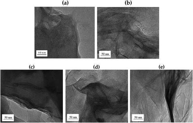 | ||
| Fig. 8 TEM micrographs of Co-TLCP hybrids containing various organoclay contents. (a) 1, (b) 3, (c) 5, (d) 7, and (e) 10 wt%. | ||
In the hybrid containing 1 wt% Cloisite 93A (Fig. 8(a)), the dispersion of clay was very good, as confirmed by the XRD results. However, because the amount of the clay used was very low, it was difficult to determine the degree of dispersion with this result. When the organoclay contained 3 wt% (Fig. 8(b)), some of the clay was agglomerated, but most of the clay was uniformly dispersed in a nano size less than 20 nm. In addition, it was found that the polymer chains were effectively inserted into the clay layer, so that each clay layer was observed, and the clay was effectively dispersed without any constant orientation. This morphology will serve as a positive factor for achieving improved thermal properties, as discussed in the next section.
However, agglomeration of the clay was observed when the organoclay content was increased to 5 wt% in the TLCP hybrid. Some clays were well dispersed, but most of the clays were observed to agglomerate at over 50 nm. This phenomenon was exacerbated when the organoclay content was increased to 10 wt%, as shown in Fig. 8(c)–(e). These results were confirmed by XRD, as shown in Fig. 7. As a result, when a large shear force owing to an external force is applied to the interface between the non-uniformly dispersed clay and the polymer, the compatibility between the polymer chain and the clay deteriorates.38
In conclusion, the most suitable organoclay content for the Co-TLCP hybrid synthesized in this study was 3 wt%. If a larger amount of organoclay is used, agglomeration of the clay will occur, which will negatively affect the overall properties of the hybrid. The properties of the TLCP hybrid according to organoclay content are described below.
3.7. Thermal behaviors of Co-TLCP hybrids
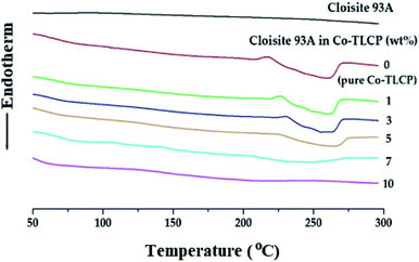
In general, when inorganic materials are mixed with organic polymer materials, the thermal properties of hybrid materials increase owing to the high thermal stability of inorganic materials. Moreover, if nano-sized fillers such as clay are dispersed in between the polymer chains, the effect of increasing the thermal properties will be maximized. Fig. 9 shows the DSC curves of the organoclay Cloisite 93A, pure Co-TLCP, and various Co-TLCP hybrids according to the wt% of organoclay. In Cloisite 93A, no transition temperature was observed in DSC, even when heated to 300 °C. In pure Co-TLCP without Cloisite 93A, Tg was observed at 103 °C, and this value gradually increased to 130 °C when the organoclay increased to 3 wt% (see Table 3). The reason for the increase in Tg on the addition of such a small amount of organoclay is that the movement is restricted as the polymer chains are inserted between the hard plate-shaped clay layers well dispersed in the polymer matrix, and eventually, the chain-segmental motion appears to be disturbed, resulting in an increase in Tg.5,39,40 In other words, even a small amount of clay greatly affects the segmental motion of the polymer chain. However, when Cloisite 93A increased from 3 to 7 wt%, Tg decreased gradually from 130 to 110 °C. This is because the excess clay in the TLCP matrix was not evenly dispersed and agglomerated.| Cloisite 93A in Co-TLCPa (wt%) | Tg (°C) | Tm (°C) | ΔHm (J g−1) | Ti (°C) | ΔHi (J g−1) | TiDb (°C) | wtR600c (%) | LC phase |
|---|---|---|---|---|---|---|---|---|
a In the chemical formula, x![[thin space (1/6-em)]](https://www.rsc.org/images/entities/char_2009.gif) : :![[thin space (1/6-em)]](https://www.rsc.org/images/entities/char_2009.gif) y = 1 y = 1![[thin space (1/6-em)]](https://www.rsc.org/images/entities/char_2009.gif) : :![[thin space (1/6-em)]](https://www.rsc.org/images/entities/char_2009.gif) 4.b 2% initial weight-loss temperature.c Weight % of residue at 600 °C.d Nematic schlieren texture.e Not observed. 4.b 2% initial weight-loss temperature.c Weight % of residue at 600 °C.d Nematic schlieren texture.e Not observed. |
||||||||
| 0 | 103 | 210 | 0.31 | 259 | 7.35 | 340 | 29 | Nem.d |
| 1 | 122 | 219 | 0.29 | 260 | 5.46 | 349 | 32 | Nem. |
| 3 | 130 | 224 | 0.24 | 260 | 4.45 | 361 | 37 | Nem. |
| 5 | 124 | 217 | 0.18 | 260 | 3.56 | 329 | 35 | Nem. |
| 7 | 110 | 190 | 0.11 | 248 | 2.70 | 312 | 33 | Nem. |
| 10 | 125 | — | — | — | — | 308 | 31 | n.o.e |
As shown in Table 3, the Tm of pure Co-TL CP was observed at 210 °C, but when Cloisite 93A was increased from 1 to 3 wt% in the Co-TLCP hybrid, the Tm increased significantly from 219 to 224 °C. This result is known to increase the Tm because it delays the heat transfer owing to the heat shielding effect of the clay dispersed in the hybrid material. The results of this study are well known in several publications.41–43 However, when the loading of the organoclay was increased from 3 to 7 wt%, the Tm of the Co-TLCP hybrid gradually decreased from 224 to 190 °C. Interestingly, when the amount of organoclay was increased to 10 wt%, the Tm of the hybrid was not observed. As the amount of clay present in Co-TLCP increases, the molecular packing and arrangement of the polymer chains mixed with the clay layer is disturbed, leading to a decrease in Tm. This result was confirmed by TEM analysis. In addition, the Tm was lowered when the excess clay agglomerated, and this result has already been published in many papers.42–44 As shown in Fig. 9, the peak intensities of the Tm peak of the Co-TLCP hybrid were very weak compared to that of pure Co-TLCP as the amount of organoclay increased. This result can be explained by the fact that the clay dispersed in the hybrid interferes with the effective molecular packing of the polymer chains, as previously described. The Tm peaks of the hybrids observed in DSC could be reliably determined using POM. In addition, the obtained heat capacity (ΔHm) was very small in the Co-TLCP hybrids dispersed with Cloisite 93A compared to pure TLCP. That is, the pure TLCP had a heat capacity of 0.31 J g−1, which gradually decreased from 0.29 to 0.11 J g−1 when the organoclay loading was increased from 1 to 7 wt%. This is because the stability of the polymer chain in the molten state is reduced as the clay content increases.
The Tis of the Co-TLCP hybrids was almost constant regardless of the amount of organoclay employed. That is, even when Cloisite 93A was increased to 5 wt%, Tis was almost constant at 260 °C, as listed in Table 3. It can be inferred that the clays dispersed in the Co-TLCP matrix had no effect on the formation of the liquid crystalline mesophase up to 5 wt%. However, low Ti (248 °C) was observed when the organoclay was dispersed in Co-TLCP at 7 wt%, as shown in Fig. 9. The ΔHi values of the hybrids gradually decreased from 7.35 to 2.70 (J g−1) as the amount of clay increased from 0 to 7 wt% because the formation of the liquid crystalline phase was disturbed as the loading of the clay increased (Table 3).
In the case of the hybrid containing 10 wt% of the organoclay, the excess clay interfered with the segmental motion of the polymer chain and showed a high Tg (125 °C), and because the liquid crystallinity of the mesogen was destroyed, Tm and Ti were not observed in the DSC. This can be seen from the fact that the clay above the critical concentration destroys the liquid crystalline phase of the hybrid.
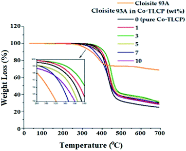
In general, when an inorganic material is introduced into an organic material, the overall thermal stability of the composite material increases owing to the high thermal stability of the inorganic material. Table 3 summarizes the thermal stability of the TLCP hybrid according to the amount of Cloisite 93A, and the TGA curves are shown in Fig. 10. The TiD of pure Co-TLCP was 340 °C, but when 3 wt% of organoclay was dispersed in TLCP, the TiD increased by 21 °C (361 °C). This phenomenon of increasing thermal stability even upon mixing a small amount of clay has already been observed in the literature. This is owing to the high attraction between the clay particles and the matrix polymer, as well as the inherent thermal stability of the inorganic clay material. In addition, the increase in thermal stability of the hybrid material because of the addition of clay can be explained by the fact that the nano-sized clay layer dispersed in the polymer matrix not only acts as a thermal barrier material but also suppresses the volatilization of polymer components that occur when heated at high temperatures.43–45 However, when the organoclay content was increased to 10 wt% in the TLCP hybrid, the TiD was greatly reduced to 308 °C. This value is the result of a 53 °C decrease of the TiD in organoclay compared to that of 3 wt%. This decrease in the TiD value is due to the agglomeration of the clay used in excess of the critical content. These results are consistent with the TEM results shown in Fig. 8. This is also due to an increase in the amount of organoclay composed of dialkoxy groups with low heat resistance.
The residual amount (wtR600) after heating at 600 °C gradually increased from 29 to 37% as the amount of organoclay increased from 0 to 3 wt% (see Table 3). This tar formation may be attributed to the high heat resistance of the clay itself. However, when the amount of organic clay was increased to 10 wt%, wtR600 decreased from 37 to 31%. As already described above, excessive amount of clay does not lead to effective thermal stability because of agglomeration, and as the amount of Cloisite 93A composed of an alkyl group increases, the residual amount decreases due to an alkyl group having low thermal stability. This phenomenon has already been observed in the TiD results.
3.8. Liquid crystalline mesophases of Co-TLCP hybrids
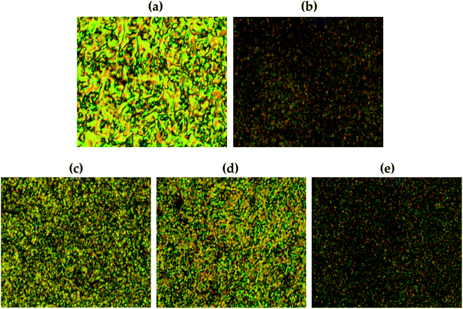
Fig. 11 shows the liquid crystalline mesophase according to the organoclay content. In pure Co-TLCP containing no clay, a threaded schlieren texture typical of nematogens was observed (Fig. 11(a)). A substantial decrease in the mesophase texture of these hybrids was observed as the organoclay content increased from 1 to 7 wt%, indicating that the liquid crystallinity decreased as the clay content increased.In POM, no birefringence was observed at any temperature in the hybrid containing 10 wt% until decomposition. As already confirmed by TEM, this suggests that higher amounts of clay aggregate more readily in the TLCP matrix than in the lower ones (see Fig. 8).
Agglomerated clay can easily disrupt the alignment of the mesogenic structures that form a liquid crystalline phase in the molten state.
4. Conclusions
In this study, ETA containing dialkoxy side groups was used as a monomer to lower the melting point and improve the processability. Co-TLCPs were synthesized using ETA and HQ at various molar ratios (1–5), and the thermal properties, crystallinity, and liquid crystallinity of the Co-TLCPs according to the number of moles of HQ were investigated and compared.When HQ was 4 moles, all properties including the thermal properties of the synthesized Co-TLCP were the best, and the stability of the liquid crystallinity was also excellent. Hybrids were prepared using Co-TLCP synthesized using 4 mol of HQ and Cloisite 93A as organoclay. In this case, 1 to 10 wt% of the organoclay was used for the Co-TLCP matrix. The thermal properties of the hybrid employing 3 wt% organoclay were the best, and the same results were also observed for the degree of dispersion, as confirmed by TEM analysis. In the Co-TLCP hybrid containing up to 7 wt% organoclay, the liquid crystalline mesophase maintained the nematic phase but was no longer observed at 10 wt%.
These results confirmed that the physical properties of the hybrids were improved when the filler was used at an appropriate critical concentration, but the physical properties decreased at concentrations higher than the critical concentration.
For a long time, TLCP has been widely used in high-strength, high-modulus polymer fibers and high-performance engineering plastics. These excellent properties and applications could be obtained by appropriately controlling the mesogenic structure constituting TLCP.
A nanocomposite is a composite in which nano-sized clay is uniformly dispersed in a polymer matrix. Due to the nanometer size of the particles, the high interfacial adhesion of the nanocomposite improves the physical properties of TLCP, so it has excellent properties and superior applicability that cannot be obtained in conventional composite materials.
Conflicts of interest
There are no conflicts to declare.Acknowledgements
This research was supported by the Basic Science Research Program through the National Research Foundation of Korea (NRF) funded by the Ministry of Education (2016R1A6A1A03012069). This work also was supported by the National Research Foundation of Korea (NRF) grant funded the Korea government (MSIT) (2022R1A2C1009863).References
- G. Guerriero, R. Alderliesten, T. Dingemans and R. Benedictus, Prog. Org. Coat., 2011, 70, 245 CrossRef CAS.
- M. Iqbal and T. J. Dingemans, Compos. Sci. Technol., 2011, 71, 863 CrossRef CAS.
- B. K. Chen, S. Y. Tsay and J. Y. Chen, Polymer, 2005, 46, 8624 CrossRef CAS.
- X. Lyu, A. Xiao, D. Shi, Y. Li, Z. Shen, E.-Q. Chen, S. Zheng, X. H. Fan and Q.-F. Zhou, Polymer, 2020, 202, 122740 CrossRef CAS.
- S. Rendon, W. R. Burghardt, R. A. Bubeck, L. S. Thomas and B. Hart, Polymer, 2005, 46, 10202 CrossRef CAS.
- T.-Y. Ha, J. H. Choi and J.-H. Chang, Polymer, 2018, 42, 41 CAS.
- Y. H. Tang, P. Gao, L. Te and C. Zhao, Polymer, 2010, 51, 514 CrossRef CAS.
- F. Sloan, 5 – Liquid crystal aromatic polyester-arylate (LCP) fibers: Structure, properties, and applications, in Structure and Properties of High-performance Fibers, ed. G. Bhat, Woodhead Publishing Series in Textiles, Duxford, UK, 2017 Search PubMed.
- W. L. Jackson, Macromolecules, 1983, 16, 1027 CrossRef CAS.
- H. Hirano, J. Kadota, Y. Agari, T. Harada, M. Tanaka and K. Hasegawa, Polym. Eng. Sci., 2007, 47, 262 CrossRef CAS.
- A. M. Nelson, G. B. Fahs, R. B. Moore and T. E. Long, Macromol. Chem. Phys., 2015, 216, 1754 CrossRef CAS.
- C. H. R. M. Wilsens, B. A. J. Noordover and S. Rastogi, Polymer, 2014, 55, 2432 CrossRef CAS.
- X. Wang, H. Bu and R. R. Luise, J. Polym. Sci., Part B: Polym. Phys., 2009, 47, 2171 CrossRef CAS.
- W. J. Jackson and H. F. Kuhfuss, J. Polym. Sci., Part A: Polym. Chem., 1976, 14, 2043 CAS.
- X. Lyu, A. Xiao, D. Shi, Y. Li, Z. Shen, E.-Q. Chen, S. Zheng, X.-H. Fan and Q.-F. Zhou, Polymer, 2020, 202, 122740 CrossRef CAS.
- R. A. Vaia and E. P. Giannelis, Polymer, 2001, 42, 1281 CrossRef CAS.
- E. P. Giannelis, Adv. Mater., 1996, 8, 29 CrossRef CAS.
- G. M. Whitesides, T. P. Mathias and C. T. Seto, Science, 1991, 254, 1312 CrossRef CAS PubMed.
- A. Usuki, A. Koiwai, Y. Kojima, M. Kawasumi, A. Okada, T. Kurauchi and O. Kamigaito, J. Appl. Polym. Sci., 1995, 55, 119 CrossRef CAS.
- R. A. Vaia, K. D. Jandt, E. J. Kramer and E. P. Giannelis, Macromolecules, 1995, 28, 8080 CrossRef CAS.
- I. Cendoya, L. Lopez, A. Alegria and C. Mijangos, J. Polym. Sci., Part B: Polym. Phys., 2001, 39, 1968 CrossRef CAS.
- M. Kawasumi, N. Hasegawa, A. Usuki and O. Akane, Mater. Sci. Eng., C, 1998, 6, 135 CrossRef.
- X. Kornmann, H. Lindberg and L. A. Berglund, Polymer, 2001, 42, 4493 CrossRef CAS.
- J.-H. Chang, B.-S. Seo and D.-H. Hwang, Polymer, 2002, 43, 2969 CrossRef CAS.
- J. Kim, G. W. Roberts and D. J. Kiserow, J. Polym. Sci., Part A: Polym. Chem., 2008, 46, 4959 CrossRef CAS.
- Y. Shoji, C. Zhang, T. Higashihara and M. Ueda, Polym. Chem., 2012, 3, 1978 RSC.
- W. J. Lee, L. K. Kwac, H. G. Kim and J.-H. Chang, Sci. Rep., 2021, 11, 11654 CrossRef CAS PubMed.
- Y. J. Kim, J. Kim and S.-G. Oh, Ind. Eng. Chem. Res., 2012, 51, 2904 CrossRef CAS.
- S. B. Damman, F. P. M. Mercx and C. M. Kootwijk-Damman, Polymer, 1993, 34, 1891 CrossRef CAS.
- D. L. Pavia, G. M. Lampman and G. S. Kriz, Introduction to Spectroscopy, Cengage Learning, Boston, MA, USA, 2008 Search PubMed.
- M. Ballauff, Makromol. Chem. Rapid Commun., 1986, 7, 407 CrossRef CAS.
- J. Majnusz and R. W. Lenz, Eur. Polym. J., 1985, 21, 565 CrossRef CAS.
- H. C. Langelaan and A. P. de Boer, Polymer, 1996, 37, 5667 CrossRef CAS.
- J.-I. Jin, J.-H. Chang and H. K. Shim, Macromolecules, 1989, 22, 93 CrossRef CAS.
- G. Galgali, C. Ramesh and A. Lele, Macromolecules, 2001, 34, 852 CrossRef CAS.
- A. B. Morgan and J. W. Gilman, J. Appl. Polym. Sci., 2003, 87, 1329 CrossRef CAS.
- G. Crevecoeur and G. Groeninckx, Polym. Eng. Sci., 1990, 30, 532 CrossRef CAS.
- Z. Yerlikaya, S. Aksoy and E. Bayramli, J. Appl. Polym. Sci., 2002, 85, 2580 CrossRef CAS.
- M. W. Noh and D. C. Lee, Polym. Bull., 1999, 42, 619 CrossRef CAS.
- S. L. C. Hsu and K. C. Chang, Polymer, 2002, 43, 4097 CrossRef CAS.
- J.-H. Chang, B. S. Seo and D. H. Hwang, Polymer, 2002, 43, 2969 CrossRef CAS.
- P. C. LeBaron, Z. Wang and T. J. Pinnavaia, Appl. Clay Sci., 1999, 15, 11 CrossRef CAS.
- J.-H. Chang, Nanomaterials, 2019, 3, 323 CrossRef PubMed.
- S. Kumar, J. P. Jog and U. Natarajan, J. Appl. Polym. Sci., 2003, 89, 1186 CrossRef CAS.
- H. I. Shin and J.-H. Chang, Polymers, 2020, 12, 135 CrossRef CAS PubMed.
Footnote |
| † Electronic supplementary information (ESI) available. See DOI: 10.1039/d2ra00795a |
| This journal is © The Royal Society of Chemistry 2022 |

