DOI:
10.1039/D2RA00789D
(Paper)
RSC Adv., 2022,
12, 10846-10854
Hydrogen production from CO2 reforming of methane using zirconia supported nickel catalyst†
Received
6th February 2022
, Accepted 1st April 2022
First published on 7th April 2022
Abstract
The use of hydrogen as an alternative fuel is an attractive and promising technology as it contributes to the reduction of environmentally harmful gases. Finding environmentally friendly cheap active metal-based catalysts for H2 rich syngas via dry reforming of methane (DRM) for industrial applications has posed a challenge. In this paper, H2 production via CO2 reforming of methane was investigated over 5Ni/ZrO2 catalysts. The catalytic performance of all prepared catalysts was evaluated in a microtubular fixed bed reactor under similar reaction conditions (i.e., activation temperature at 700 °C, feed flow rate of 70 ml min−1, reaction temperature 700 °C for 440 min reaction time) of CO2 reforming of methane. Different characterization techniques such as; BET, CO2-TPD, TGA, XRPD, Raman, and TEM, were used. The study of the textural properties of catalysts established that the BET of pristine catalyst (5NiZr) was enhanced by the addition of modifiers and promoters. A bimodal TPR distribution in the reduction temperature range of 250–550 °C was recorded. In the CO2-TPD analysis, the strength of basicity came in this order: 5Ni15YZr > 5Ni10YZr > 5Ni5YZr > 5NiZr > 5Ni20YZr. The investigation of catalyst modifiers (MgO and Y2O3) resulted in the Y2O3 modifier improving the activity and catalytic performance better than MgO, which generated a hydrogen yield of 22%. 15% Y2O3 modifier loading gave the highest H2 yield 53% in the phase of different loadings of yttria. The study of the influence of promoters (Cs, Ga, and Sr) revealed that the catalytic performance of 5Ni15YZr catalysts promoted with Sr towards the H2 yield enhanced the activity to 62%. The promoted catalysts displayed lower carbon deposition compared to the unpromoted catalyst, which provided 25.6 wt% weight loss.
1. Introduction
Almost 85% of the total world's energy is coming from fossil fuels. Yet the global demand for energy, obtained from coal and fossil oils, is growing and this has a negative influence on the environment causing global warming, acid rain, greenhouse gas (GHG) emissions, climate change, and ozone holes.1,2 According to the agreement of the Kyoto Protocol, and the Paris Agreement on climate change, the major greenhouse gases are nitrogen oxides, carbon dioxide, methane, hydro-fluorocarbon, per-fluorocarbon, and sulfur hexafluoride.3,4 More attention needs to be paid to CO2 and CH4 because they are chiefly responsible for global warming. Increasing the worldwide consumption of electricity needs the development of exact intelligent methods and algorithms for its projection. Among the techniques is the genetic algorithm which optimizes and uses stochastic search.5 G. Aydin et al., modeled the coal consumption and its future demand in turkey using trend analysis.6 In another work, the investigators elaborated on the major sources of methane emissions in energy production and its mitigation options from the energy sector.7 In the light of all obstacles that emerged from using fossil fuels, hydrogen, as a transportation fuel and a chemical for industry,8 has drawn immense attention due to its high specific energy density.9 Hydrogen is an environmentally friendly fuel, which can be used for powering engines, producing electricity, and for other numerous industrial applications.10 There are many sources for producing hydrogen mostly sustainable ones like biomass, water, coal, oil, and natural gas with different processes of production.11 The conversion of methane or different hydrocarbons to hydrogen-rich syngas (admixture of carbon monoxide and hydrogen) is accomplished by steam reforming, partial oxidation, and CO2 reforming of methane.12 CO2 reforming of methane (CRM) is an attractive method to produce hydrogen-rich syngas from the reaction of carbon dioxide with hydrocarbons such as methane.13 CRM is seen as one of the most cost-effective methods to reduce global warming and encourage chemical and energy industries to use resources more sustainably. The CRM reaction is represented by:| | |
CH4 + CO2 → 2CO + 2H2
| (1) |
Researchers have made huge efforts to acquire appropriate catalysts for reforming catalysts to increase conversion, hydrogen yield and reduce coke formation.14 Noble metal-based catalysts are expensive and have limited availability and researcher resorted to using transitional metals such as Ni-based catalysts.15,16 However, Ni-based catalysts are deactivated by the sintering and deposition of carbon. Therefore, the activity and stability of performance of catalysts depend on size, support, promoters, acid–base properties, and oxidation states of the metals.17–19 Arif et al.; used Ni/ZrO2 and Ni/CaO catalysts for producing hydrogen via CO2 dry reforming of glycerol.20 Ni-based catalysts can be improved by adding basic modifiers such as MgO and CeO2.21 Dong et al.; reported the impact of changing the amount of nickel on the conversion of methane into syngas over Ni/Ce–ZrO2 catalyst.22 Liu et al.; employed Ni–ZrO2@SiO2 and little coking and sintering of nickel particles were noted.23 Fakeeha et al.; studied the effect of doping La2O3 and WO3 on the decomposition of methane by the Fe–Ni catalyst over the ZrO2 support.24 Their study revealed that the La2O3 doped ZrO2 support resulted in the maximum decomposition of methane to hydrogen with relatively high stability. Zhang et al.; investigated the stabilization of the metastable structure of ZrO2 by reflux treatment and the improvement of Ni/ZrO2 catalyst for CRM.25 Their results improved the stability, performance, and coke resistance of the Ni/ZrO2 catalyst. Wang et al.; promoted the Ni/ZrO2 catalyst with silica in CRM.26 High conversions of CH4 and CO2 and long stability were accomplished. Therdthianwong et al.; examined the influence of ZrO2 as a catalyst and promoter.27 For CRM. They found the ZrO2 additive fundamentally enhanced the coke resistance of Ni/Al2O3. Abasaeed et al.; investigated the influence of catalysts calcination temperature on the production of H2 over ceria- and zirconia-supported cobalt catalysts in CRM.28 Higher activity and H2 yield resulted over the catalysts, calcined at lower temperatures, than those, calcined at higher temperatures. Wolfbeisser et al.; reported catalytic restraint of Ce1−xZrxO2, ZrO2 and CeO2 supported for Ni nanoparticles in CRM.29 They found that ZrO2 gave the best results in terms of decreasing coke formation, stability, and activity. Ibrahim et al.; examined the impact of adding phosphate (PO4) to Ni/ZrO2 catalyst for the CRM process.30 They found out that the loading of Ni affected significantly the catalytic activity and stability and that phosphate was essential for promoting the catalyst. Sheng et al.; investigated the performance of Ni and Co nanoparticles within ZrO2 hollow sphere in CRM.31 The Ni0.8Co0.2/H–ZrO2 catalyst displayed the highest activity and stability owing to the strong metal–support interaction phenomenon, which in turn inhibited the sintering of metal nanoparticles at high temperatures. Pompeo et al.; investigated the stability advancement on Ni/α-Al2O3 catalysts improved by the addition of CeO2 and/or ZrO2 to produce H2 from CRM.32 They found that the addition of small quantities of CeO2 and ZrO2 to α-Al2O3 upgraded the activity and stability. Al-Fakeeha et al.; tested the promoted and non-promoted 5% Co–5% Ni/Al2O3–ZrO2 catalyst with iridium in CRM.33 They found that the addition of Ir had a significant impact on activity by increasing the conversions of CO2 and CH4 by 20%, decreasing the carbon deposition, and improving the reducibility of the active catalyst. To avoid the deposition of carbon, the catalysts can be altered by the addition of promoters, being alkaline and alkaline earth metals.34 Cao et al.; examined the effect of cerium promoter on the activity of cobalt over gamma-alumina applied in dry reforming of methane.35 They found that the dispersion of the active metal over the support and its reducibility was markedly improved. Sha et al.; investigated the promotional effect of Ga towards the CO2 hydrogenation to methanol.36 Their results exhibited that the Ga promoter enhanced the adsorption and activation of H2 and CO2, thus improving the catalytic performance of methanol synthesis from CO2 hydrogenation. The contributions of the previous investigators are summarized and tabulated in Table S1.†
In view of the above, it has been identified that CRM is a promising technique that produces hydrogen in an efficient way using ZrO2 supported catalysts over a range of different materials. However, it has been a less focused area and has not been studied systematically despite its promising results in producing hydrogen. In this work, Ni-based catalysts supported on ZrO2 will be prepared by the wet impregnation method and implemented on CRM to produce H2 and CO. The effect of certain stabilizers such as MgO and Y2O3 of the support and the influence of their various loadings on the overall performance of CO2 reforming of methane was investigated. The study also covered the use of promoters like Sr, Cs, and Ga and their impacts on the process.
2. Experimental
2.1 Materials
Nickel nitrate hexahydrate [Ni(NO3)2·6H2O], gallium nitrate hydrate [Ga(NO3)3·6H2O], strontium nitrate tetrahydrate [Sr(NO3)2·4H2O], and cesium nitrate [CsNO3] with 99% purity was purchased from Sigma-Aldrich. The zirconia (ZrO2) support was obtained from Anhui Elite industrial with 99% purity. Yttria (Y2O3, 99.9%) were bought from MKnano Co. Magnesium oxide (MgO, 99.9%) was purchased from Sigma-Aldrich. Distilled water was used for impregnation. The catalyst designation in Table S2,† preparation, testing, and characterizations are given in the support information.
3. Results
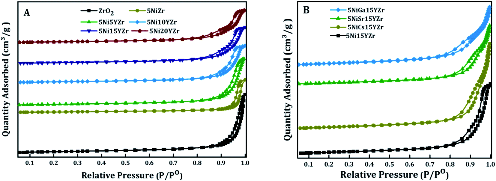
The textural properties of the fresh catalysts for both non-promoted and promoted catalysts were studied using nitrogen adsorption–desorption isotherms (Fig. 1). The results of isotherms are presented in Fig. 1A and B. In accordance with IUPAC classifications of isotherms, the isotherms are of type IV, typical of mesoporous materials, with an H3-type hysteresis loop, which resulted from capillary condensation and evaporation at high relative pressures.37 The relative pressure increased in the range of 0.8–1.0 P/P0. In addition, all catalysts had low specific surface areas which were reflected by their low specific volume adsorbed of nitrogen gas, lying in the range of 4.5–8.0 cm3 g−1. The structure of the support was not changed by the incorporation of the active metal and promoter.
 |
| | Fig. 1 N2 adsorption–desorption isotherms curves for (A) non-promoted, (B) promoted Ni catalysts. | |
 |
| | Fig. 2 H2-TPR profiles of the synthesized catalysts. | |
Table 1 summarizes the BET surface and porosity. Sole ZrO2 support showed a specific surface area of 21 m2 g−1, which decreased to 16 m2 g−1 upon impregnation of NiO, an indication of the successful loading process onto the surface of the support. However, the pore size increased from 37 nm for meso-ZrO2 to 42 nm after loading NiO because of the decomposition of nickel(II) nitrate hexahydrate and evolution of H2O, NO2, HNO3, and O2 gases during the calcination step.38 The BET surface area of the catalysts increased when the Y2O3 was added and this was associated with the decrease of the NiO crystal size, shown by the XRD results in Table 1, and the creation of O2 vacancy.39 The incorporation of promoters enhanced the BET by providing extra active sites, while the pore volume and size remained almost the same (Table 1).
Table 1 The textural aspect of the catalysts
| Catalyst |
BET surface area (m2 g−1) |
Pore volume (PV) (cm3 g−1) |
Pore size (nm) |
NiO crystal size (nm) |
| ZrO2 |
21 |
0.16 |
37 |
— |
| 5NiZr |
16 |
0.15 |
42 |
31.6 |
| 5Ni5YZr |
27 |
0.23 |
31 |
15.8 |
| 5Ni10YZr |
23 |
0.19 |
25 |
15.8 |
| 5Ni15YZr |
25 |
0.18 |
24 |
13.8 |
| 5Ni20YZr |
24 |
0.17 |
22 |
16.4 |
| 5NiCs15YZr |
28 |
0.20 |
28.4 |
— |
| 5NiGa15YZr |
30 |
0.15 |
20.0 |
— |
| 5NiSr15YZr |
26 |
0.14 |
23 |
— |
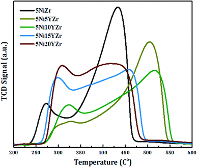
Fig. 2 displays the reducibility of the catalysts using H2-TPR analysis. In general, all samples have the same classification which is bimodal at 250–550 °C, but with different patterns, and the amounts of hydrogen consumed for the reduction are shown in Fig. 3. After 600 °C there is no more NiO left to reduce. 5NiZr catalysts have a unique reduction behavior and the highest reduction peak at 434 °C with high hydrogen consumption. Primarily, the nature of support material dominates the extent of synergy that exists within catalyst components. Adding the Y2O3 to the support significantly affected the reduction in terms of temperature range and hydrogen consumption. When the Y2O3 load is less or equal to 10 wt%, the interaction between the active metal and support increases, thus shifting the peaks to higher temperatures. On the contrary, if the Y2O3 load is more than 10 wt%, suitable interaction between the Ni and support at medium temperature ranges was obtained. The Y2O3 load catalysts have higher hydrogen consumptions than that of 5NiZr catalysts at the lower zone indicating the presence of freer NiO species.
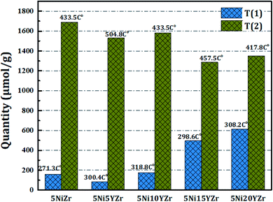 |
| | Fig. 3 The quantity of hydrogen consumption during TPR analysis. | |
The catalytic basicity has a strong effect on CRM reaction and therefore the acidity of the prepared catalysts is determined using the CO2-TPD technique as shown in Fig. 4. The area of CO2 desorption peak and temperature range determines the basicity strength which is weak (50–200 °C), medium (200–400 °C), strong (400–650 °C), very strong (>650 °C).40,41 The CO2-TPD profiles show the CO2 desorption peaks fall in the weak and medium zones. With the exception of 5Ni10YZr and 5Ni15YZr catalysts, where the CO2 desorption peaks appeared in the very strong range at 665 °C. These desorption peaks are accredited to strength basic sites.42 Based on these results, the basicity order is as follows: 5Ni15YZr > 5Ni10YZr > 5Ni5YZr > 5NiZr > 5Ni20YZr. The catalytic activity was enhanced by homogenous scatter of surface acid-basic sites, consequently lowering the tendency of coke deposition.
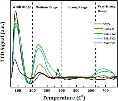 |
| | Fig. 4 CO2-TPD patterns of prepared catalysts. | |
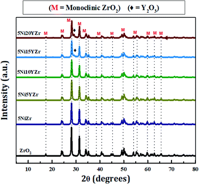
Fig. 5 shows the XRPD patterns of synthesized catalysts at 2θ° = 5–80°. The XRPD pattern demonstrates only one crystalline phase formation of ZrO2. The patterns are identical, but the intensity decreases with the increase in Y2O3 due to the reduction in the size of the NiO crystal, and the Y2O3 peaks appear clearly as the loading increases. The size of NiO crystals tabulated in Table 1 is determined by the Debye–Scherrer equation. Upon analyzing diffraction data using MDI Jade® software (version 6.5, Materials Data Inc., Newtown Square, PA, USA). The monoclinic phase of ZrO2 is identified at 24.17, 28.14, 31.47, 34.25, 38.58, 40.89, 44.87, 49.24, 54, 55.40, 57.25, 58, 60, 62.70, 65, 69, 71.30, 75 and 79° (JCPDS 81-1314)43 while NiO diffraction peaks are identified at 35.34 and 45.5° (JCPDS 65-5745).44 The quantity of NiO is so small in the presence of ZrO2 support and hence its peaks are totally overlapped by those of ZrO2. The Y2O3 peaks are identified at 29.20, 31, and 50.20° (JCPDS 89-5592).45 The Y2O3 peaks exhibit similar features to that of NiO. However, when its loading goes beyond 10% small distinct peaks begin to appear. Scherrer's equation was employed to compute the crystallite size, which can be described as follows:
| |
Dp = K × λ/β![[thin space (1/6-em)]](https://www.rsc.org/images/entities/char_2009.gif) cosθ cosθ
| (2) |
in which,
Dp is the crystallite size in nanometers,
K is the shape factor which is 0.94,
λ is the wavelength of X-ray,
β is the full width at half maximum of the diffraction peak of the sample, and
θ is the diffraction angle in degrees.
 |
| | Fig. 5 The XRPD patterns of synthesized catalysts. | |
The modification of the support structure by adding appropriate modifiers influences the catalytic performance. In this work, two modifiers (MgO and Y2O3) were used as stabilizers for the zirconia support due to their potential advantages. Five weight% of the modifiers were considered separately. Fig. 6 exhibits the catalytic performance in terms of H2-yield versus time on stream. The result displays that the initial H2-yield of 5NiZr, 5Ni5MgZr, and 5NiYZr are 41, 24, and 51% respectively. While the average conversion for 440 min time stream of 5NiZr, 5Ni5MgZr, and 5NiYZr are 36, 23, and 47% respectively. From the figure, it is obvious that the incorporation of modifiers alters the activity performance. The Mg modifier inhibits the reaction and decreased the H2-yield by about 36%, while the Y modifier increased about 31% over the pristine support (Zr). Having seen that the Y modifier is better than Mg one, it is plausible to check the different loadings of Y to find out the optimum.
 |
| | Fig. 6 H2-yield% versus time on stream for stabilized-zirconia catalysts at a reaction temperature of 700 °C. | |
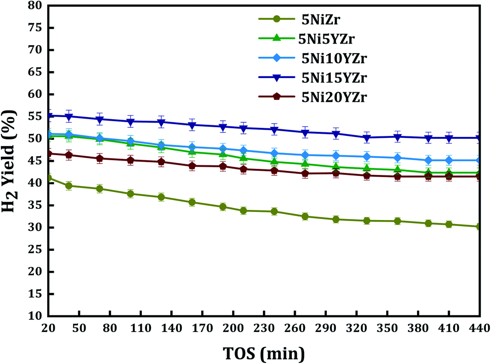
Normally, CH4 adsorption on reduced Ni surface is the rate-determining step for CRM, which is promoted by stable H2 atoms adsorption on strong H2 binding sites of the reduced Ni atom. Fig. 7 shows the H2 yield over 440 min of reaction. The conversion of the 5Ni15YZr catalyst has the highest hydrogen yield compared to the other catalysts. The hydrogen yield profile is in this decreasing order 5Ni15YZr > 5Ni10YZr > 5Ni5YZr > 5Ni20YZr > 5NiZr. The figure displays that the H2 yield increases with the Y2O3 load up to 15 wt% due to the interaction of the active metal and its dispersion in the pores of the support. On the other hand, increasing the Y2O3 load to 20 wt% leads to a significant decrease in the activity of the catalyst even lower than that of 5 wt%. Several researchers46–49 have studied similar systems where the impact of lanthanide metal oxides and alkaline earth to the active metals supported on them brings the appearance of surface oxygen vacancies. The coke formation is the main reason for the inactivity of the catalyst due to blockage of the pores of the catalyst and stopping the feed flow through it.
 |
| | Fig. 7 H2 yield% versus time on stream for different loading of yttria-stabilized-zirconia catalysts at a reaction temperature of 700 °C. | |
For the quantification of carbon deposited, TGA analysis of the used catalysts obtained after 440 min of reaction was carried out as shown in Fig. 8. The weight loss started at 470 °C due to the combustion of carbon formed on the surface of the catalyst, which had a huge role in inhibiting the activity of the catalysts.50 The percentage of weight loss equals the percentage of the amount of carbon formed. However, the addition of Y2O3 to 5NiZr at low loading (0.0, 5.0, 10.0, and 15.0 wt%) did not significantly influence the carbon deposition and thus, the enhancement due to the Y2O3 may be attributed to the reduction of active metal agglomeration. On the other hand, the high loading sample 5Ni20YZr gave quite less carbon formation. The order of the weight loss% of the samples is as follows: 5Ni5YZr > 5Ni10YZr > 5Ni15YZr > 5NiZr > 5Ni20YZr.
 |
| | Fig. 8 TGA profile for spent catalysts at 700 °C. | |
For a better understanding of morphology and carbon formation, TEM was performed in Fig. 9. The TEM micrographs of the best (5Ni15YZr) and the basic (5NiZr) catalysts were analyzed using both fresh and used samples. It is shown for fresh samples that the promoted catalyst has better distribution and smaller active metal particles size, while for spent samples, 5NiZr exhibits sintering and bulky layers due to the increase in the particle size of the nickel. Whereas the 5Ni15YZr contains slim layers of multiwall carbon nanotubes.
 |
| | Fig. 9 TEM micrographs and matching particle size distribution: (A) and (B) for fresh and (C) and (D) for spent catalysts of 5NiZr, and 5Ni15YZr respectively at a reaction temperature of 700 °C. | |
The performance Ni supported on stabilized zirconia is further upgraded by incorporation of active metal with elements like (Cs, Ga, and Sc). Fig. 10 illustrates the catalytic performance of H2-yield% against the time on stream performance. In this work, a fixed 3 wt% of promoters were adopted. The result displays that the initial H2-yield of 5Ni15YZr, 5Ni15CsYZr, 5Ni15GaYZr, and 5Ni15SrYZr are 55.3, 56.6, 60.6, and 63.4% respectively. The Cs, Ga, and Sr promoters enhanced the H2-yield% by 3%, 12.5%, and 19% respectively over the non-promoted “5Ni15YZr”. Thus, the 5Ni15SrYZr catalyst outperforms all other catalysts and hence generates the highest average H2-yield% of 62%. The work of previous investigators is compared with the present one as shown in Table 2. It is evident that the present catalyst provides a higher hydrogen yield than those catalysts operated at the same reaction temperature of 700 °C.
 |
| | Fig. 10 H2 yield% versus time on stream for different promoters of yttria-stabilized-zirconia catalysts at a reaction temperature of 700 °C. | |
Table 2 Performance comparison results
| Catalyst |
Wt. (g) |
Tr |
GHSV (L g−1 h−1) |
Y (%) |
Ref. |
| NiSr/Y2O3–ZrO2 |
0.1 |
700 |
42 |
62 |
This work |
| Ni5Ce/La2O3–ZrO2 |
0.1 |
800 |
42 |
85 |
51 |
| Ni2Ce/Y2O3ZrO2 |
0.1 |
800 |
28 |
80 |
52 |
| Ni–Si/ZrO2 |
0.25 |
450 |
14.4 |
4.3 |
26 |
| Ni–Zr/SiO2 |
0.25 |
450 |
14.4 |
3.5 |
26 |
| Ni@ZrO2–SiZr-7.7 |
0.1 |
800 |
72 |
81 |
53 |
| 0.8% Ni + 0.2% Co–MgAl2O4 |
0.5 |
700 |
54 |
51 |
54 |
| 10Ni + 1% Fe–MgAl2O4 |
0.1 |
750 |
30 |
78 |
55 |
| Ni–Pd/SiO2-Imp. |
0.1 |
700 |
24 |
45 |
56 |
| Ni/CeO2–ZrO2 |
0.1 |
700 |
30 |
33 |
57 |
| Ni/L2O3 + CeO2 |
0.15 |
800 |
40 |
40 |
58 |
The TGA analysis was performed for the used promoted catalysts obtained after 440 min of reaction. Fig. 11 displays the % weight loss profiles. The produced carbon is in line with the activity of the promoted catalysts. Therefore, the most reactive promoted catalyst (5Ni15SrYZr) generates the highest amount of carbon (9.7% weight loss) while the least reactive catalyst (5Ni15CsYZr) promoted catalyst produced the minimum carbon deposition (2.6% weight loss). All promoted catalysts revealed less carbon deposition compared to the non-promoted catalyst (5Ni15YZr) which gives 25.6% weight loss.
 |
| | Fig. 11 TGA profile for promoted spent catalysts at 700 °C. | |
Raman spectroscopic analysis was carried out to reveal the structure of carbon deposits over the spent catalysts. Fig. 12 displays the Raman spectra of the used promoted catalysts. The Raman study indicates a structural change in 5Ni15YZr after the incorporation of promoters. 5NiGa15YZr and 5NiCs15YZr catalysts depict three bands with Raman shifts in the range of 816–857 cm−1, 966–979 cm−1 and 1112–1115 cm−1, while the three bands of NiSr15YZr catalyst, somewhat shifted to the lower values of Raman shift, appear at 654 cm−1, 885 cm−1, and 1006 cm−1. The non-promoted catalyst (5Ni15YZr) displays a single peak in a similar range at 612 cm−1. The three weak peaks for the promoted catalyst can be ascribed to the induced disorders in the graphite (D), the ideal vibration of the graphite layers (G), and the overtone of the D band (D2).59 Normally, the intensity ratio of the D band to the G band (i.e. ID/IG) provides the extent of the crystalline order of graphite in carbonaceous materials.60 Values of ratios obtained are 0.84, 0.88, and 0.74 for 5NiGa15YZr, 5NiCs15YZr, and 5NiSr15YZr catalysts respectively, indicating a high degree of graphitization.
 |
| | Fig. 12 Raman spectra for the used promoted catalysts. | |
4. Conclusions
Hydrogen production via DRM was investigated over a 5Ni/ZrO2 catalyst. The effect of Y2O3 modifier loading (i.e., 0.0, 5.0, 10.0, 15.0, 20.0 wt%), were examined. All catalysts gave low specific surface areas in accordance with their low specific volume adsorption of N2. But, the BET surface area of the catalysts increased when the modifiers and promoters were added. Both in the H2-TPR and CO2-TPD analysis, the addition of Y2O3 had a positive effect as it lowered the temperature of reduction and reduced hydrogen consumption during the activation process, and increased the basicity. On the other hand, increasing the Y2O3 modifier improved the catalytic performance, hydrogen production, and reduced carbon deposition. The 15 wt% Y2O3 catalyst (5Ni15YZr) was found to be the optimum. The TEM analysis displayed the formation of nano-filament containing multiwall carbon nanotubes. The promotion of the catalysts brought about reduction in carbon deposition. The promoting effects of Ni supported on 15 wt% Y2O3 displayed that Sr promoter was better than Cs and Ga promoters. The Raman analysis of used promoted catalysts depicted the different forms of carbon deposited and the dominance of the graphitic structure.
5. Recommendations
The hydrogen production, over the 5Ni/ZrO2 catalyst via DRM investigated, was prepared using the impregnation technique. Therefore, it suggested the catalysts be prepared by other methods so as to compare them. The variation of operating conditions is also recommended, by testing higher reaction temperatures of the obtained best catalyst. The utilization of different stabilizers and promoters is recommended. Moreover, the study of the kinetics and the mechanism of the system used is recommended. Finally, the use of other cost-effective active elements such as Co or their combination with Ni is recommended.
Conflicts of interest
There are no conflicts to declare.
Acknowledgements
The all authors wish to acknowledge the support of Researchers Supporting Project number (RSP-2021/368), King Saud University, Riyadh, Saudi Arabia.
References
- F. Martins, C. Felgueiras, M. Smitkova and N. Caetano, Energies, 2019, 12, 964 CrossRef CAS.
- S. Oros-Ruiz, R. Zanella, R. López, A. Hernández-Gordillo and R. Gómez, J. Hazard. Mater., 2013, 263, 2–10 CrossRef CAS PubMed.
- A. Tiwari, Adv. Mater. Lett., 2021, 12(10), 1–5 CrossRef.
- T. Stangarone, Clean Technol. Environ. Policy, 2020, 23, 509–516 CrossRef PubMed.
- A. Azadeh and S. Tarverdian, Energy Policy, 2007, 35(10), 5229–5241 CrossRef.
- G. Aydin, S. Kaya and I. Karakurt, Proceedings of the 24th International Mining Congress and Exhibition Of Turkey, IMCET 2015, Antalya, Turkey, April 14-17, 2015 Search PubMed.
- G. Aydin, I. Karakurt and K. Aydiner, Energy Sources, Part A, 2012, 34, 967–982 CrossRef CAS.
- M. Momirlan and T. Veziroǧlu, Renewable Sustainable Energy Rev., 1999, 3, 219–231 CrossRef CAS.
- S.-H. Liu and H.-R. Syu, Appl. Energy, 2012, 100, 148–154 CrossRef CAS.
- M. G. A. Rubio and K. Jaojaruek, 2016 International Conference on Cogeneration, Small Power Plants and District Energy, 2016 DOI:10.1109/COGEN.2016.7728949.
- M. Hirscher, T. Autrey and S.-i. Orimo, ChemPhysChem, 2019, 20, 1157 CrossRef CAS PubMed.
- R. J. Press, K. S. V. Santhanam, M. J. Miri, A. V. Bailey and G. A. Takacs, ChemSusChem, 2009, 2, 781 CrossRef.
- A. Al-Fatesh, S. K. Singh, G. S. Kanade, H. Atia, A. H. Fakeeha, A. A. Ibrahim, A. M. El-Toni and N. K. Labhasetwar, Int. J. Hydrogen Energy, 2018, 43, 12069–12080 CrossRef CAS.
- W.-J. Jang, J.-O. Shim, H.-M. Kim, S.-Y. Yoo and H.-S. Roh, Catal. Today, 2019, 324, 15–26 CrossRef CAS.
- A. Steinfeld, Int. J. Hydrogen Energy, 2002, 27, 611–619 CrossRef CAS.
- J. Xu, W. Zhou, Z. Li, J. Wang and J. Ma, Int. J. Hydrogen Energy, 2009, 34, 6646–6654 CrossRef CAS.
- L. Chen, Z. Qi, S. Zhang, J. Su and G. A. Somorjai, Catal, 2020, 10, 858 CrossRef CAS.
- Z. Zuo, S. Liu, Z. Wang, C. Liu, W. Huang, J. Huang and P. Liu, ACS Catal., 2018, 8, 9821–9835 CrossRef CAS.
- D. P. Harrison, in Industrial and Engineering Chemistry Research, American Chemical Society, 2008, vol. 47, pp. 6486–6501 Search PubMed.
- N. N. M. Arif, D.-V. N. Vo, M. T. Azizan and S. Z. Abidin, Bull. Chem. React. Eng. Catal., 2016, 11, 200–209 CrossRef CAS.
- M.-S. Fan, A. Z. Abdullah and S. Bhatia, Int. J. Hydrogen Energy, 2011, 36, 4875–4886 CrossRef CAS.
- W.-S. Dong, H.-S. Roh, K.-W. Jun, S.-E. Park and Y.-S. Oh, Appl. Catal., A, 2002, 226, 63–72 CrossRef CAS.
- W. Liu, L. Li, X. Zhang, Z. Wang, X. Wang and H. Peng, J. CO2 Util., 2018, 27, 297–307 CrossRef CAS.
- A. H. Fakeeha, S. O. Kasim, A. A. Ibrahim, A. S. Al-Awadi, E. Alzahrani, A. E. Abasaeed, A. E. Awadallah and A. S. Al-Fatesh, Front. Chem., 2020, 8, 317 CrossRef CAS PubMed.
- M. Zhang, J. Zhang, X. Zhang, Z. Zhou, F. Song, Q. Zhang, Y. Tan and Y. Han, Energy Convers. Manage., 2020, 216, 112950 CrossRef CAS.
- Y. Wang, L. Yao, Y. Wang, S. Wang, Q. Zhao, D. Mao and C. Hu, ACS Catal., 2018, 8, 6495–6506 CrossRef CAS.
- S. Therdthianwong, A. Therdthianwong, C. Siangchin and S. Yongprapat, Int. J. Hydrogen Energy, 2008, 33, 991–999 CrossRef CAS.
- A. E. Abasaeed, A. S. Al-Fatesh, M. A. Naeem, A. A. Ibrahim and A. H. Fakeeha, Int. J. Hydrogen Energy, 2015, 40, 6818–6826 CrossRef CAS.
- A. Wolfbeisser, O. Sophiphun, J. Bernardi, J. Wittayakun, K. Fottinger and G. Rupprechter, Catal. Today, 2016, 277, 234–245 CrossRef CAS.
- A. A. Ibrahim, A. S. Al-Fatesh, W. U. Khan, S. O. Kasim, A. E. Abasaeed, A. H. Fakeeha, G. Bonura and F. Frusteri, Int. J. Hydrogen Energy, 2019, 44, 27784–27794 Search PubMed.
- K. Sheng, D. Luan, H. Jiang, F. Zeng, B. Wei, F. Pang and J. Ge, ACS Appl. Mater. Interfaces, 2019, 11, 24078–24087 CrossRef CAS PubMed.
- F. Pompeo, D. Gazzoli and N. N. Nichio, Int. J. Hydrogen Energy, 2009, 34, 2260–2268 CrossRef CAS.
- A. H. Fakeeha, A. A. Ibrahim, Y. Arafat, H. Atia, A. E. Abasaeed and A. S. Al-Fatesh, Can. J. Chem. Eng., 2018, 96, 955–960 CrossRef CAS.
- R. Franz, R. Franz, T. Kühlewind, G. Shterk, E. Abou-Hamad, A. Parastaev, E. Uslamin, E. J. M. Hensen, F. Kapteijn, J. Gascon and E. A. Pidko, Catal. Sci. Technol., 2020, 10, 3965–3974 RSC.
- A. N. T. Cao, C. Q. Pham, L. K. H. Pham, D. Le Tri Nguyen, P. T. T. Phuong, T. T. V. Tran, V.-P. Nguyen, T. B. Nguyen, Q. Van Le, N. A. Nguyen and T. M. Nguyen, Int. J. Hydrogen Energy, DOI:10.1016/j.ijhydene.2021.11.077.
- F. Sha, C. Tang, S. Tang, Q. Wang, Z. Han, J. Wang and C. Li, J. Catal., 2021, 404, 383–392 CrossRef CAS.
- D. M. Oliveira and A. S. Andrada, Cerâmica, 2019, 65, 170–179 CrossRef CAS.
- W. Brockner, C. Ehrhardt and M. Gjikaj, Thermochim. Acta, 2007, 456, 64–68 CrossRef CAS.
- P. J. B. Marcos and D. Gouvêa, Cerâmica, 2004, 50, 38–42 CrossRef CAS.
- A. S. Al-Fatesh, M. A. Naeem, A. H. Fakeeha and A. E. Abasaeed, Bull. Chem. Soc. Jpn., 2013, 86, 742–748 CrossRef CAS.
- M. A. Naeem, A. S. Al-Fatesh, A. E. Abasaeed and A. H. Fakeeha, Fuel Process. Technol., 2014, 122, 141–152 CrossRef CAS.
- A. H. Fakeeha, A. S. Al Fatesh, A. A. Ibrahim, A. N. Kurdi and A. E. Abasaeed, ACS Omega, 2021, 6, 1280–1288 CrossRef CAS PubMed.
- P. R. Rauta, P. Manivasakan, V. Rajendran, B. B. Sahu, B. K. Panda and P. Mohapatra, Phase Transitions, 2012, 85, 13–26 CrossRef CAS.
- H. Lu, M. Zheng, J. Chen, N. Li, L. Xue and J. Cao, Integr. Ferroelectr., 2011, 127, 128–133 CrossRef CAS.
- H.-Y. Jung, H.-J. Kim, S. Yang, Y.-G. Kang, B.-Y. Oh, H.-G. Park and D.-S. Seo, Liq. Cryst., 2012, 39, 789–793 CrossRef CAS.
- W.-P. Dow, Y.-P. Wang and T.-J. Huang, Appl. Catal., A, 2000, 190, 25–34 CrossRef CAS.
- W.-P. Dow and T.-J. Huang, J. Catal., 1996, 160, 171–182 CrossRef CAS.
- K. Kawamura, K. Watanabe, T. Hiramatsu, A. Kaimai, Y. Nigara, T. Kawada and J. Mizusaki, Solid State Ionics, 2001, 144, 11–18 CrossRef CAS.
- J. B. Wang, Y.-L. Tai, W.-P. Dow and T.-J. Huang, Appl. Catal., A, 2001, 218, 69–79 CrossRef CAS.
- X. Du, L. J. France, V. L. Kuznetsov, T. Xiao, P. P. Edwards, H. AlMegren and A. Bagabas, Appl. Petrochem. Res., 2014, 4, 137–144 CrossRef CAS.
- J. Khatri, A. S. Al-Fatesh, A. H. Fakeeha, A. A. Ibrahim, A. E. Abasaeed, S. O. Kasim, A. I. Osman, R. Patel and R. Kumar, Mol. Catal., 2021, 504, 111498 CrossRef CAS.
- A. H. Fakeeha, A. S. Al Fatesh, A. A. Ibrahim, A. N. Kurdi and A. E. Abasaeed, ACS Omega, 2021, 6, 1280–1288 CrossRef CAS PubMed.
- Z. Y. Lim, J. Tu, Y. Xu and B. Chen, J. Colloid Interface Sci., 2021, 590, 641–651 CrossRef CAS PubMed.
- M. H. Aghaali and S. Firoozi, Int. J. Hydrogen Energy, 2021, 46, 357–373 CrossRef CAS.
- R. L. B. A. Medeiros, H. P. Macedo, V. R. M. Melo, Â. A. S. Oliveira, J. M. F. Barros, M. A. F. Melo and D. M. A. Melo, Int. J. Hydrogen Energy, 2016, 41, 14047–14057 CrossRef CAS.
- C. Pan, Z. Guo, H. Dai, R. Ren and W. Chu, Int. J. Hydrogen Energy, 2020, 45, 16133–16143, DOI:10.1016/j.ijhydene.2020.04.066.
- A. Kambolis, H. Matralis, A. Trovarelli and C. Papadopoulou, Appl. Catal., A, 2010, 377, 16–26 CrossRef CAS.
- N. D. Charisiou, G. Siakavelas, L. Tzounis, V. Sebastian, A. Monzon, M. A. Baker, S. J. Hinder, K. Polychronopoulou, I. V. Yentekakis and M. A. Goula, Int. J. Hydrogen Energy, 2018, 43, 18955–18976 CrossRef CAS.
- S. Reich and C. Thomsen, Philos. Trans. R. Soc., A, 2004, 362, 2271–2288 CrossRef CAS PubMed.
- Y. Kameya and K. Hanamura, Chem. Eng. J., 2011, 173, 627–635 CrossRef CAS.
Footnote |
| † Electronic supplementary information (ESI) available. See DOI: 10.1039/d2ra00789d |
|
| This journal is © The Royal Society of Chemistry 2022 |
Click here to see how this site uses Cookies. View our privacy policy here. 
 Open Access Article
 This Open Access Article is licensed under a Creative Commons Attribution-Non Commercial 3.0 Unported Licence
 *,
Abdullah A. Alquraini,
Ahmed E. Abasaeed and
Anis H. Fakeeha
*,
Abdullah A. Alquraini,
Ahmed E. Abasaeed and
Anis H. Fakeeha