
 Open Access Article
 This Open Access Article is licensed under a Creative Commons Attribution-Non Commercial 3.0 Unported Licence
Continuous flow Meerwein–Ponndorf–Verley reduction of HMF and furfural using basic zirconium carbonate†
Henrique Magri Marçon and
Julio Cezar Pastre*
and
Julio Cezar Pastre*
Institute of Chemistry, University of Campinas – UNICAMP, PO Box 6154, Zip Code 13083-970, Campinas, SP, Brazil. E-mail: jpastre@unicamp.br; Tel: +55 (19) 3521 31 43
First published on 11th March 2022
Abstract
Continuous Flow Microreactors and Green Chemistry are areas with promising applications, especially when allied. In this scenario, the main goal of this study was to develop new strategies for the synthesis of bio-based compounds under a flow regime. We worked towards the flow synthesis of furfuryl alcohol and DHMF (dihydroxymethylfuran), from their respective aldehydes, through a Meerwein–Ponndorf–Verley reaction with iso-propanol catalysed by basic zirconium carbonate. Furfuryl alcohol was prepared in essentially quantitative yield with productivities as high as 67 mg min−1. Efforts towards DHMF synthesis were performed and the process was also optimized using design of experiments. The optimal conditions were defined for DHMF at 0.25 M and were determined to be 120 °C and 50 s of residence time, giving yields of up to 99% and productivity of 50 mg min−1. The use of a FT-IR device for the in-line continuous monitoring was pivotal for the fast optimization of the processes, securing steady-state operations, and design of experiments ensured a greater understanding of the effect of temperature, residence time and concentration, alongside their interactions in yield, selectivity and productivity.
Introduction
The chemical industry is based on many organic compounds that are extracted from non-renewable sources. However, modern environmental conditions urge the transformation of the chemical industry to biomass upgrading, where platform chemicals play an important role. The US Department of Energy has selected key compounds (known as platform molecules) for chemical biorefining, which were further updated by Bozell and Petersen.1,2 Among them, there are the furans: furfural (5) and 5-(hydroxymethyl)furfural (HMF; 6). They can be prepared from the dehydration of abundant C5 and C6 sugars (Fig. 1), respectively, and can be transformed into a myriad of important products: THF (7), 2-MeTHF (8), and furfuryl alcohol (9) from furfural; and DHMF (10), FDCA (11), and levulinic acid (12, and its alkyl esters) from HMF.3–5 These compounds can, for example, be used in the synthesis of polymers and are important intermediates to reduce our fossil-dependency and mitigate environmental issues.6 Therefore, many chemists have turned their attention to developing the synthesis of the platform chemical of furans.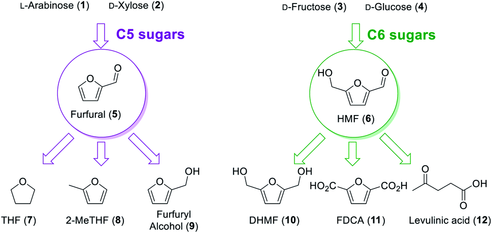 | ||
| Fig. 1 Biomass sources of furfural and HMF platform chemicals and some of their derivatives. | ||
In our laboratory, we have previously worked on the dehydration of fructose to HMF in continuous flow regime and we have decided to carry on with the further valorisation of these compounds.7,8 Herein, we studied the conversion of HMF and furfural into their corresponding alcohols, DHMF and furfuryl alcohol. Both these transformations were studied under continuous flow regime in a fixed-bed reactor.
Continuous flow chemistry presents opportunities for the development of greener processes.9 Typical factors favouring continuous flow processes are the high mass and heat transfer efficiencies, ensuring smaller gradients of temperature, concentration, etc., when compared to batch reactors leading to improved reaction selectivity.10 Additionally, solvents can be safely handled on temperatures above their boiling point with the use of back pressure regulators, expanding physicochemical conditions available for biomass conversion. Another key point is that heterogeneous catalysts can be packed in a column (or fixed-bed reactors) and be reused for long periods, as well as being readily recovered. Finally, flow chemistry can facilitate process scale-up while maintaining a small production footprint.11 As a result, this enabling chemical technology is key for process intensification of platform chemicals.12
Furfuryl alcohol (9) has been used as starting material for the synthesis of resins in the foundry industry.13–15 Although the reduction of the carbonyl group of furfural is enough to produce furfuryl alcohol, it is still a challenging process to develop in large scale. The first patented reduction process yielding furfuryl alcohol was developed by Quaker Oats Company in 1928.16 Since then, different catalysts were evaluated to avoid catalyst deactivation. Currently, Cu-chromite catalyst is widely used because of its high efficiency yielding 95–98% of furfuryl alcohol at 100–160 °C and 10–20 MPa of hydrogen.13
Dihydroxymethylfuran (DHMF, 10) is derived from HMF (6) through reduction of the aldehyde moiety to its corresponding alcohol. DHMF can be used as a monomer for the synthesis of polymers, replacing non-renewable sources.17 The presence of the s-cis diene in the ring can also be used for developing novel smart materials, such as vitrimers and self-healing polymers.18–21 A major issue regarding the use of biomass compounds is their high cost for large scale production. Hence, efficient chemical processes for the synthesis of these derivatives are needed.
The major chemical reduction pathway used for the production of furfuryl alcohol and DHMF is hydrogenation over metal catalysts. Recently, the Meerwein–Ponndorf–Verley reaction has been increasingly present in the literature as an alternative for the reduction of biomass-derived compounds. Studies range from new Lewis acid materials, cascade reactions and non-conventional systems.15,22–27 Other researchers have explored hydrous zirconia in continuous flow for hydride transfer reactions, although not focusing on biomass-derived compounds.28,29 We have decided to explore a commercially available basic zirconium carbonate as catalyst under liquid-phase continuous flow conditions.
The mechanism for the MPV reduction typically involves a Lewis acid that can coordinate a carbonyl and a hydride donor, most frequently an alcohol.30,31 The catalytic cycle consists of the aldehyde coordination to a zircon(IV) site, followed by hydride migration from the alcohol to the carbonyl. Then, there is the ligand exchange between the products and the alcohol, which is frequently used as solvent (Fig. 2).
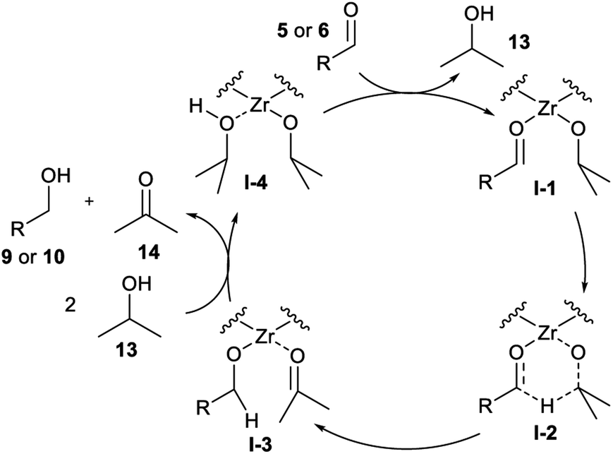 | ||
| Fig. 2 General mechanism for Meerwein–Ponndorf–Verley reduction. | ||
Meerwein–Ponndorf–Verley reduction has been evaluated, using ZrIV as Lewis acid. Lin et al. used ZrO(OH)2 and ethanol to circumvent the need for more dangerous hydrogen sources. They have achieved 89% DHMF yield and 95% HMF conversion at 150 °C for 2.5 hours.32 However, their catalyst could not be recycled without diminishing yields, even calcination at 300 °C did not recover the catalyst's activity. Unfortunately, HMF is known to be prone to rehydration towards levulinic acid and polymerization, forming humins.33 Hence, it is an important scientific challenge to develop a mild and selective reduction process of HMF towards producing DHMF.
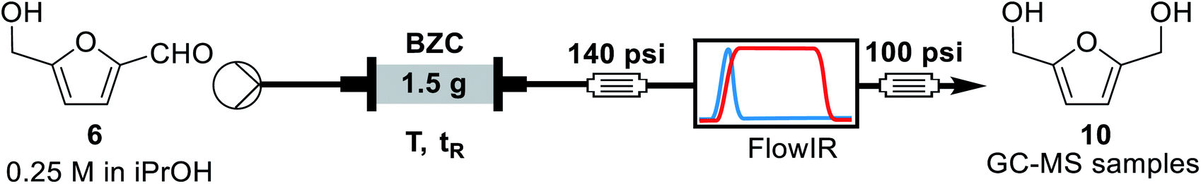
Our goal was to prepare furfuryl alcohol (9) and DHMF (10) via Meerwein–Ponndorf–Verley reduction (MPV reduction) over a ZrIV catalyst. Various alcohols have been previously studied by Li and co-workers, showing iso-propanol to be the most efficient.30 Therefore, we aimed using a mild, efficient, and low-cost reducing agent – iso-propanol – to drive the formation of furfuryl alcohol and DHMF (Scheme 1).
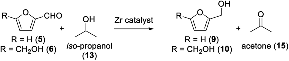 | ||
| Scheme 1 Reduction of furfural and HMF to their respective alcohols studied. | ||
Results
Preliminary catalyst evaluation in batch
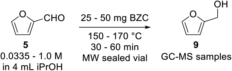
Our preliminary investigation in batch for the Meerwein–Ponndorf–Verley reduction of furfural and HMF using basic zirconium carbonate (BZC) are reported in Tables 1 and 2. The catalyst was used by Feng and co-workers for the reduction of biomass derived aldehydes under batch conditions and, according to their work, BZC exhibits better catalytic performance than most zirconium catalysts such as ZrO(OH)2 (ref. 34) and Zr(OH)4, etc.30,35 We have also explored this material under microwave (MW) heating observing the effect of different reaction parameters: temperature (entries 5 and 8), catalyst loading (entries 4, 5 and 6), and concentration (entries 6 and 7).
|
|||||||
|---|---|---|---|---|---|---|---|
| # | T (°C) | C (mol L−1) | Catalyst (mg) | t (min) | Conversion (%) | Yieldb (%) | |
| a Reaction conditions: basic zirconium carbonate, 4 mL of iso-propanol and furfural were sealed in a microwave vial and were heated at the specified temperature for the specified time in a microwave reactor.b Yield determined by GC-MS analysis using trimethoxybenzene as internal standard. | |||||||
| 1 | 150 | 0.0335 | 25 | 30 | 90 | 90 | |
| 2 | 150 | 0.0335 | 25 | 60 | 100 | Quant. | |
| 3 | 150 | 0.125 | 25 | 30 | 82 | 70 | |
| 4 | 150 | 0.25 | 25 | 30 | 82 | 55 | |
| 5 | 150 | 0.25 | 37.5 | 30 | 83 | 72 | |
| 6 | 150 | 0.25 | 50 | 30 | 83 | 79 | |
| 7 | 150 | 1.0 | 50 | 30 | 56 | 53 | |
| 8 | 170 | 0.25 | 37.5 | 30 | 92 | 86 | |
|
|||||
|---|---|---|---|---|---|
| # | C (mol L−1) | Catalyst (mg) | t (min) | Conversion (%) | Yieldb (%) |
| a Reaction conditions: basic zirconium carbonate, 4 mL of iso-propanol and HMF were sealed in a microwave vial and were heated at 150 °C for the specified time in a microwave reactor.b Yield determined by GC-MS analysis using trimethoxybenzene as internal standard. | |||||
| 1 | 0.0335 | 25 | 30 | 100 | Quant. |
| 2 | 0.0335 | 25 | 60 | 100 | Quant. |
| 3 | 0.125 | 25 | 30 | 87 | 87 |
| 4 | 0.25 | 25 | 30 | 71 | 71 |
| 5 | 0.25 | 37.5 | 30 | 75 | 76 |
| 6 | 0.25 | 50 | 30 | 90 | 90 |
| 7 | 1.0 | 50 | 30 | 77 | 18 |
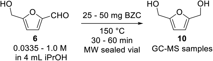
The results can be compared alongside Feng's as univariate experiments and the conclusions drawn from Tables 1 and 2 are straightforward. Longer reaction times results in higher yields, having the substrate allowed for time to react. Higher reaction temperatures also improve the kinetics of the reaction, as expected from the Arrhenius equation (entries 5 and 8). Also, higher catalyst loadings improved the conversion and yield in both substrates (entries 4, 5 and 6). Another factor studied was the effect of the concentration of substrate. Higher concentrations resulted in lower conversions (entries 6 and 7), which is expected because there is more substrate to react over the same quantity of catalyst. Running the reaction under microwave heating allowed for a quick and efficient screening of conditions. For sake of comparison, Feng reported yield of 97% for reactions at 80 °C in 5 hours and 91% at 180 °C in 15 minutes, under conventional heating. At this point, we decided to move on and evaluate this transformation under continuous flow conditions.
Before performing continuous flow experiments and optimization through design of experiments, we need to ensure the reasonable long-term stability of the catalyst under the rection conditions. To define temperature thresholds, thermogravimetric analysis (TGA) and differential scanning calorimetry (DSC) of the material were performed (Fig. S1†). Thus, the upper temperature limit was defined as 120 °C to limit catalyst decomposition and evolution of properties during the reaction.
Catalyst evaluation in continuous flow regime
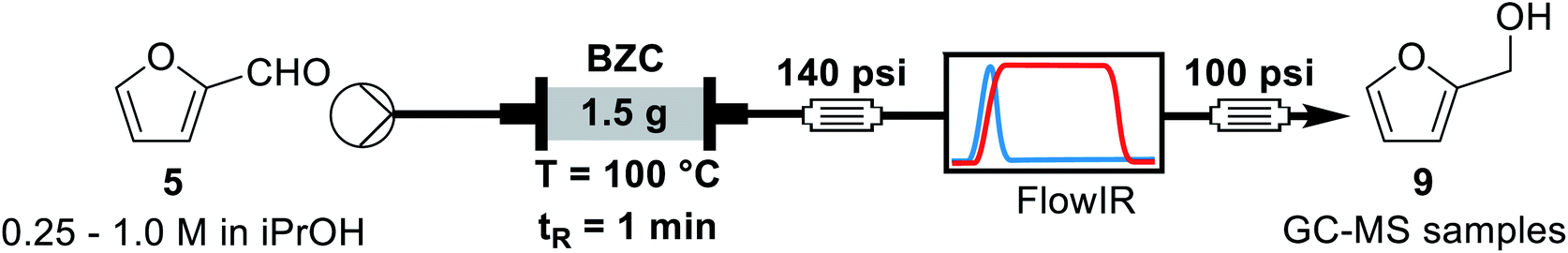
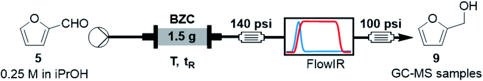
For the continuous flow setup (Scheme 2), we used a solution of the aldehyde (5 or 6) in iso-propanol, which was pumped through a column of basic zirconium carbonate. The column outlet is connected to an in-line FTIR analyser. The pressure was maintained by using an appropriate back-pressure regulator, allowing to easily study conditions at higher temperature than the solvent boiling point (boiling point at 1 atm = 78 °C).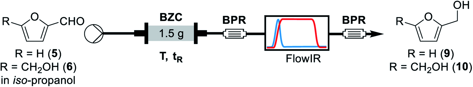 | ||
| Scheme 2 General flow chemistry setup for the reduction of furfural and HMF to their alcohols. | ||
Initially, since HMF is a reactive substrate prone to side-reactions, we have focused on better understanding the system by using furfural because it is a more stable and easier to process substrate (Table 3). All experiments were performed over the same catalyst column in the order herein presented.
|
||||
|---|---|---|---|---|
| # | T (°C) | tR (min) | Conversion (%) | Yieldb (%) |
| a Reaction conditions: a 0.25 M solution of furfural in iso-propanol was pumped through a BZC column at the respective temperatures and residence times. Samples were collected after stabilisation, as monitored by FT-IR for yield determination by GC-MS.b Yield determined by GC-MS analysis using trimethoxybenzene as internal standard. | ||||
| 1 | 60 | 1.0 | 48 | 48 |
| 2 | 60 | 2.0 | 85 | 84 |
| 3 | 80 | 2.0 | 98 | 83 |
| 4 | 80 | 1.0 | 87 | 88 |
| 5 | 100 | 1.0 | Quant. | Quant. |
| 6 | 100 | 0.5 | 67 | 69 |
| 7 | 120 | 0.5 | 91 | 91 |
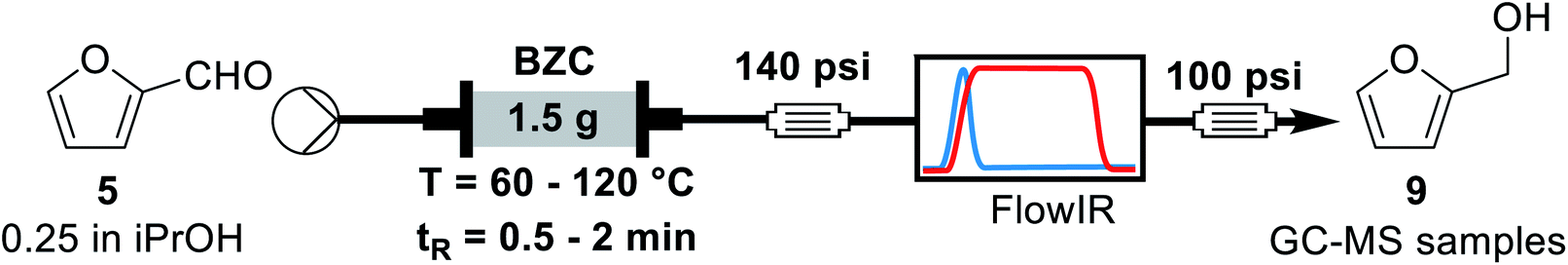
Previous rationalization for batch experiments also explains the data observed in Table 3. Longer residence times and higher reaction temperatures increase conversion and yield (entries 1, 2 and 4, 5, respectively). The conservation of the mass balance is observed, within experimental error, for all entries. Under the best conditions (100 °C and 1 min of residence time), furfuryl alcohol could be obtained in quantitative yield. In this scenario, the use of the heterogeneous catalyst in continuous flow regime represents a considerable advantage over the batch reaction since it facilitates product isolation and minimizes unity operations. After this exploratory analysis, we decided to study additional reaction parameters. Thus, we performed a long-term experiment varying the back-pressure regulator. Considering that the transition-state for the MPV reaction involves approaching the aldehyde and the secondary alcohol with the catalyst in a tight transition state, a higher pressure can facilitate the reaction. Additionally, the higher pressure can lead to a higher packing of the catalyst column and its effect on the reaction system must be evaluated. Hence, we analysed the stability of the catalyst column for furfural and the effect of changing the pressure of the system (Table 4).
|
||||
|---|---|---|---|---|
| # | Run time (h) | BPR (psi) | Conversion (%) | Yieldb (%) |
| a Reaction conditions: a 0.25 M solution of furfural in iso-propanol was pumped through a BZC column at 100 °C and 1 minute residence time. After 2 hours the backpressure was increased from 100 to 240 psi, after 2 additional hours the backpressure was reduced back to 100 psi. Samples were collected after stabilisation, as monitored by FT-IR, for yield determination by GC-MS.b Yield determined by GC-MS analysis using trimethoxybenzene as internal standard. | ||||
| 1 | 0–2 | 100 | 99 | 86 ± 5 |
| 2 | 2–4 | 240 | 98 | 93 ± 3 |
| 3 | 4–6 | 100 | 97 | 86 ± 6 |
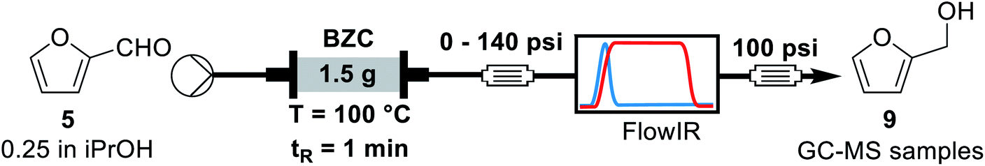
First, we evaluated the 100 psi BPR maintaining the system pressurized for 2 hours. For another 2 hours another 140 psi BPR was added in series, the system works as an equivalent 240 psi BPR. Afterwards, the system pressure was restored to 100 psi for more than 2 hours. Fractions were collected every 30 minutes to check stability. We observed that increasing the system pressure slightly increased the yield of the reaction (p-value = 0.004, two-tailed Student test at 95% confidence). It is also important to observe that for entries 1 and 3, the yield achieved was maintained, indicating that the column activity was not affected for experiments at 100 °C, residence time of 1 minute and 0.25 M. Overall, around 94 mmol of furfural was processed over this 4.9 mmol catalyst column (1.5 g of BZC). Noteworthy, we observed little to no catalyst deactivation during a few hours under these conditions.
The next parameter evaluated was the effect of concentration of furfural. For this experiment, we used the same standard condition as previously: 100 °C, 1 min residence time, 1.5 g of catalyst and a 250 psi BPR. All experiments were performed over the same catalyst column in the order shown in Table 5.
|
|||
|---|---|---|---|
| # | C (mol L−1) | Conversion (%) | Yieldb (%) |
| a Reaction conditions: a solution of furfural in iso-propanol was pumped through a BZC column at 100 °C and 1 minute residence time. Samples were collected after stabilisation, as monitored by FT-IR for yield determination by GC-MS. Then the solution was switched to a different furfural concentration. All entries were done over the same catalyst column.b Yield determined by GC-MS analysis using trimethoxybenzene as internal standard. | |||
| 1 | 0.25 | 90 ± 1 | 90 ± 2 |
| 2 | 0.50 | 82 ± 3 | 82 ± 3 |
| 3 | 1.0 | 57 ± 4 | 57 ± 2 |
| 4 | 2.0 | 33 ± 4 | 31 ± 4 |
| 5 | 0.25 | 60 ± 2 | 61 ± 2 |
The results are consistent with those achieved under batch conditions. Larger quantities of material demand higher temperatures or reaction times. Hence, the reaction yield and conversion decrease for higher concentrations, from 0.25 to 2.0 M. Entries 1 and 5 are on the same conditions, showing that the catalyst's activity reduced over time. A few factors can explain this effect. During the experiments of Table 5, we operated far from optimal conditions for entries 3 and 4. This can result on side-reactions and reduction of available active sites due to the adsorption of by-products, such as humins (see ESI, Fig. S2†). Another possible factor is related to the maximum turnover of the catalyst, because we processed a larger quantity of material (around 170 mmol of furfural per 1.5 g of basic zirconium carbonate). Finally, we decided to concentrate our efforts on the process optimization using design of experiments to observe a global scenario of possible interactions between parameters.
Process optimization through DoE
Our final goal was to evaluate the influence of each variable in the reduction process and the interaction between them using design of experiments. We used the Design Expert software from Stat-Ease for the modelling (for statistical results, including ANOVA, see ESI†).36 Design of experiments is a powerful statistical tool that allows us greater understanding the effect of multiple variables, alongside their interactions on a measured response such as yield or productivity. The first substrate evaluated was furfural using a face-centred composite design with three factors (Table 6) – residence time, temperature, and concentration – at 2 levels, 1 central point for each face of the cubic design and with 6 central points of the design.
|
||||||
|---|---|---|---|---|---|---|
| # | T (°C) | tR (s) | C (mol L−1) | Conversion (%) | Yieldb (%) | Productivity (mg min−1) |
| a Reaction conditions: a solution of furfural in iso-propanol at different concentrations was pumped at different flow rates through a BZC column at different temperatures. Each entry was run with a freshly packed column.b Yield determined by GC-MS using trimethoxybenzene as internal standard. | ||||||
| 1 | 80 | 50 | 0.25 | 79 | 64 | 23 |
| 2 | 120 | 50 | 0.25 | 100 | 99 | 35 |
| 3 | 80 | 200 | 0.25 | 100 | 100 | 8.8 |
| 4 | 120 | 200 | 0.25 | 100 | 96 | 8.5 |
| 5 | 80 | 50 | 1.0 | 52 | 43 | 60 |
| 6 | 120 | 50 | 1.0 | 94 | 85 | 120 |
| 7 | 80 | 200 | 1.0 | 95 | 85 | 30 |
| 8 | 120 | 200 | 1.0 | 85 | 62 | 22 |
| 9 | 80 | 125 | 0.625 | 94 | 93 | 33 |
| 10 | 120 | 125 | 0.625 | 72 | 58 | 20 |
| 11 | 100 | 50 | 0.625 | 84 | 76 | 67 |
| 12 | 100 | 200 | 0.625 | 61 | 49 | 11 |
| 13 | 100 | 125 | 0.25 | 100 | 96 | 14 |
| 14 | 100 | 125 | 1.0 | 96 | 83 | 47 |
| 15 | 100 | 125 | 0.625 | 85 | 71 | 25 |
| 16 | 100 | 125 | 0.625 | 78 | 65 | 23 |
| 17 | 100 | 125 | 0.625 | 97 | 93 | 33 |
| 18 | 100 | 125 | 0.625 | 94 | 84 | 29 |
| 19 | 100 | 125 | 0.625 | 99 | 83 | 29 |
| 20 | 100 | 125 | 0.625 | 93 | 87 | 31 |
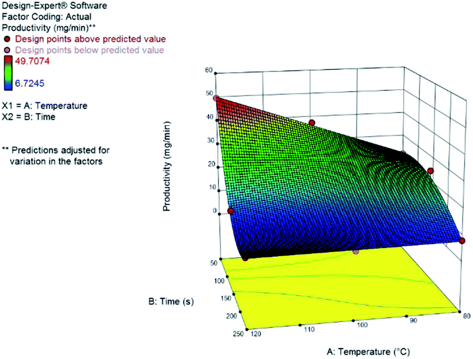
Yield results presented a large variance with respect to the design space, as can be seen from the central point replicates. Hence, we could not build an appropriate statistical model for the yield. Nonetheless, milder reaction conditions (low temperature) and longer reaction times resulted in higher yields. Productivity, on the other hand, could be statistically modelled using a transformation of the response to logarithmic scale – as suggested by the Box–Cox plot at the Design Expert software, version 10. The model consists of a reduced cubic model, with various interaction factors. The model equation and the 3D response surface (Fig. 3) in coded variables, are presented.
log10![[thin space (1/6-em)]](https://www.rsc.org/images/entities/char_2009.gif) productivity = 1.43 − 0.10A − 0.40B + 0.24C − 0.081AB − 0.012A2 + 0.006B2 + 0.14A2B + 0.14AB2 productivity = 1.43 − 0.10A − 0.40B + 0.24C − 0.081AB − 0.012A2 + 0.006B2 + 0.14A2B + 0.14AB2 |
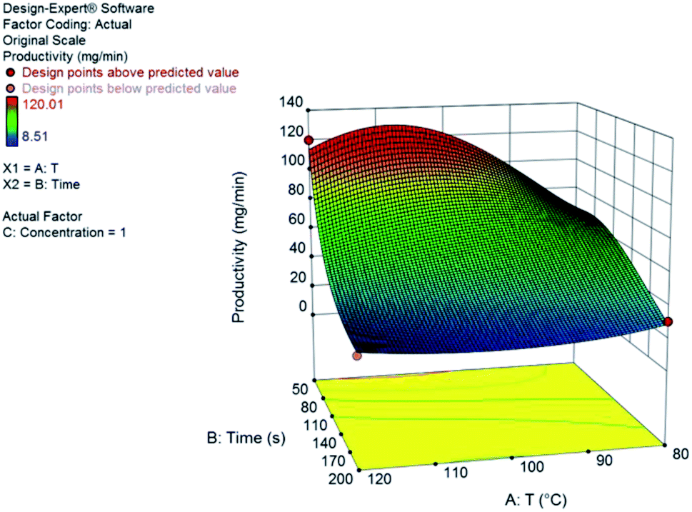 | ||
| Fig. 3 Response surface for the productivity, in mg min−1, of furfuryl alcohol from furfural at 1.0 M. Coded variables are A for temperature and B for residence time. | ||
The continuous flow system has shown greater productivity at higher concentrations, lower residence times and higher temperatures. We observe large positive interaction coefficients for A2B and AB2 (A is the coded variable for temperature and B is the coded variable for residence time); also, concentration has a strong positive effect on productivity. Using lower residence times will increase the productivity of the system as expected and determined by the large negative value of the B coefficient. Furthermore, using high temperatures can lead not only to a higher conversion of the aldehyde but also to the formation of small quantities of aldol by-products (Fig. S3†) without compromising the reaction development.
Concluding the development of the reduction of furfural to furfuryl alcohol, we have performed a long-term experiment to evaluate the system's stability and catalyst recyclability. The system was set to a condition of high yield – to avoid the formation and build-up of side-products – and high productivity by working at 120 °C, 0.25 M and residence time of 50 s for 7 hours. Samples were collected and analysed for 4.5 hours, while in steady-state operation. The flow chemistry setup for the scale-up experiments involves the connection of iso-propanol and the aldehyde solution, driven by a piston pump towards the bottom of the packed column reactor. Afterwards the crude passes through 140 psi BRP, the FlowCell of the ReactIR and another 100 psi BPR before collection as shown in Fig. 4.
 | ||
| Fig. 4 General flow chemistry setup for scale-up experiments: (A) solutions of aldehyde and iso-propanol, (B) packed-bed column reactor, (C) FlowCell IR detector and (D) collection flask. | ||
Yield was determined using GC-MS analysis with internal standard and aliquots were taken and analysed each 30 minutes of run time to evaluate the system's stability. The catalyst activity slightly diminished with time, going from 97% to 85% after 5.5 hours (Fig. 5 and 6). Nonetheless, the process can be used for reducing furfural to furfuryl alcohol with good efficiency. The overall catalytic process yields a catalytic loading of 3 mol%.
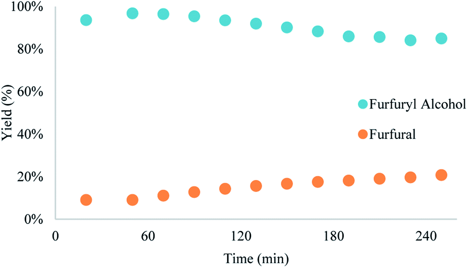 | ||
| Fig. 5 Results of the scale-up reduction of furfural, with slight decrease in catalytic activity. Reaction conditions: a 0.25 M solution of furfural in iso-propanol was pumped through a BZC column at 120 °C and 50 s residence time for 5.5 hours. | ||
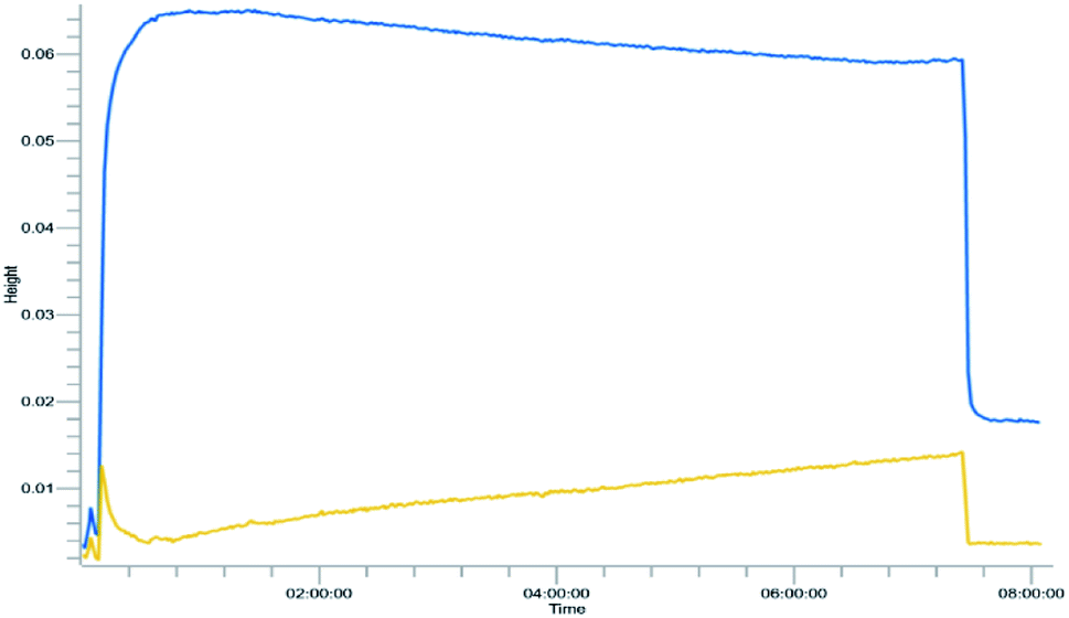 | ||
| Fig. 6 Trend analysis of furfural reduction for the scale-up reduction. Wavenumbers selected: 1713 cm−1 (blue) to acetone and 1680 cm−1 (yellow) for the aldehyde. Reaction conditions: a 0.25 M solution of furfural in iso-propanol was pumped through a BZC column at 120 °C and 50 s residence time for 5.5 hours. | ||
From the trend analysis of the FTIR for furfural reduction (Fig. 6), we can observe that the signal corresponding to the unreacted aldehyde increases significatively over time, while the acetone signal diminishes. This result agrees with data from Fig. 6. Having completed the reaction analysis for furfural, we decided to expand our efforts towards synthesizing of DHMF. Because our previous results showed only a linear influence of the concentration and HMF is more prone to the production of oligomers and polymers (humins) at higher concentration,27 we have decided to evaluate only two variables – residence time and temperature – in this optimization. The performed design was also a central composite design with the axial points at the edges of the squared design space to generate an adequate response surface and account for the curvature of the system. The results of this design are presented in Table 7.
|
|||||
|---|---|---|---|---|---|
| # | tR (s) | T (°C) | Conversion (%) | Yieldb (%) | Productivity (mg min−1) |
| a Reaction conditions: a solution of HMF in iso-propanol was pumped at different flow rates through a BZC column at different temperatures. Each entry was run with a freshly packed column.b Yield determined by GC-MS using trimethoxybenzene as internal standard. | |||||
| 1 | 50 | 80 | 50 | 47 | 22 |
| 2 | 250 | 80 | 86 | 86 | 7.9 |
| 3 | 50 | 120 | Quant. | 99 | 50 |
| 4 | 250 | 120 | 78 | 75 | 7.1 |
| 5 | 150 | 100 | 95 | 92 | 16 |
| 6 | 150 | 100 | 88 | 87 | 13 |
| 7 | 150 | 100 | 88 | 88 | 14 |
| 8 | 150 | 120 | 68 | 67 | 13 |
| 9 | 250 | 100 | 74 | 73 | 6.7 |
| 10 | 150 | 80 | 85 | 85 | 24 |
| 11 | 50 | 100 | 82 | 82 | 38 |
Once again, we have successfully built a statistical model for productivity but not for yield. This can be explained by the low dispersion of yields observed under most conditions evaluated. The model that accounts for the observed results is also a reduced cubic model with various interaction terms between residence time and temperature. The model equation and the 3D response surface, in coded variables, are presented below and in Fig. 7.
| Productivity (DHMF) = +16.03 − 14.64A − 5.79B − 7.08AB + 5.85A2 + 12.45A2B |
 | ||
| Fig. 7 Response surface for the productivity, in mg min−1, of DHMF from HMF. | ||
The best productivity conditions of the continuous flow system were at low residence times (50 s) and high temperatures (120 °C), as expected based on the previous results for furfural. Throughput is larger at increased flow rates and conversion of HMF increases with temperature. Because of the possible side-reactions – oligomerization and hydration – the short reaction times provides improved yields since it avoids the over exposition of the product to the catalyst which would lead to the formation of humins or rehydration to levulinic acid.
We have followed up with a long-term experiment as scale-up procedure at the optimal conditions (both in terms of yield and productivity) of 50 s, column temperature of 120 °C and concentration of 0.25 M. The HMF solution was pumped through the system for 7 hours and the yield was measured in 30 minutes intervals. Compared with the hydrogen transfer of furfural, the yield diminished consistently with time for the MPV reduction of HMF (Fig. 8); the same was observed in the in-line FTIR monitoring (Fig. S12†). We believe it results from side-products that can adsorb in reactive zirconium sites, compromising the catalytic activity and reusability of the catalyst when HMF was used as feedstock. This data agrees with previous experiments and the dark brown colour of the column could be due to more carbon accumulation (see Fig. S2† for the colour change of the BZC). Although the reaction proved to be efficient for the reduction of small amounts of HMF to DHMF, the process still needs to be further developed for proper scaling-up.
 | ||
| Fig. 8 Results of the scale-up reduction of HMF, with major decrease in catalytic activity. Reaction conditions: A 0.25 M solution of HMF in iso-propanol was pumped through a BZC column at 120 °C and 50 s residence time for 5.5 hours. | ||
Experimental
General
Commercially available reagents and solvents were used without further purification, unless otherwise stated. Basic zirconium carbonate was acquired from Sigma-Aldrich, product SKU 14616, lot BCBW5143. 1H and 13C NMR spectra were recorded on a Bruker DPX-250 and Avance III 500 MHz spectrometers. Chemical shifts (δ) are given in parts per million, referenced to the residual peak of CDCl3, δ = 7.26 (1H NMR) and δ = 77.0 (13C NMR) as internal references. The following abbreviations were used to designate chemical shift multiplicities: s = singlet, br s = broad singlet, d = doublet, t = triplet, q = quartet, m = multiplet. GC-MS analysis was performed on a 9870A Agilent GC system. The chromatographic column was an Agilent HP-5MS (60 m length, 0.25 mm diameter, and 0.25 μm film). The injector and MS source temperatures were 280 and 230 °C, respectively. The MS ionization impact was set at 70 eV and the mass spectrometer was operated with a mass scan range of 30–400 m/z. All microwave experiments were carried out using a Biotage Initiator+ Microwave Synthesizer using a 5 mL pressurized vial. All continuous flow experiments were carried out using the Vapourtec R2/R4 modules. The FTIR in-line monitoring data were recorded using the DS Micro Flow Cell connected to the ReactIR 45 from Mettler Toledo. Continuous flow reactions were statistically evaluated by Design Expert software version 10 (Stat-Ease).General procedure for reactions in batch with basic zirconium carbonate
A 2–5 mL Biotage microwave vial was loaded with 1 mmol of substrate (Furfural or HMF), basic zirconium carbonate, and 4 mL of iso-propanol (for experiments at 0.25 M; the amount of substrate was properly adjusted for other concentrations). The vial was sealed and heated in a Biotage MW reactor for the specified time at the specified temperature. Afterwards, 25 mg of internal standard was added, homogenized and the mixture was decanted for 30 minutes. An aliquot was taken and diluted to ∼1 mg mL−1 and analysed through GC-MS.General procedure for reactions in flow with basic zirconium carbonate
A solution of the aldehyde, furfural or HMF, was prepared by weighting the aldehyde and completing the appropriate volume with iso-propanol. The mixture was protected from light and stirred for 5 minutes to ensure homogeneity. An Omnifit HiT column (6.6 mm diameter) was packed with 1.5 g of basic zirconium carbonate between two small pads of 0.100 g of Celite at both ends to avoid leaching and/or clogging (void volume = 1.2 mL, measured by weight difference between the dry column and the column filled with iso-propanol in the next step – technique known as picnometry). The column was washed with iso-propanol at room temperature and 0.5 mL min−1 flow rate for 30 minutes, with a BPR of 250 psi at the outlet of the reactor. Afterwards, the BPR was switched for a setup with a 40 psi, followed by a 100 psi BPR, a ReactIR45 coupled with a flow-cell and a final 100 psi BPR. When the hardware was in the final configuration, the flow rate and temperature were adjusted and iso-propanol was pumped through the system for 3 residence times (for tR = 50 s, flowrate = 1.44 mL min−1); then, the valves were switched to pump the aldehyde solution. Samples of 3 mL were collected once the output stream was stable (around 30 minutes, at tR = 50 s). Steady-state operation was determined according to FT-IR monitoring. Multiple samples (3–5) were collected per entry to ensure the system had reached stationary state. Aliquots from the collected samples were diluted to proper concentration with a solution of trimethoxybenzene (internal standard) in iso-propanol (C = 1.0 g L−1) and analysed by GC-MS.Conclusions
From the experiments presented, we have stablished a novel procedure for the reduction of furfural and HMF under liquid-phase continuous flow regime using iso-propanol as reducing agent and basic zirconium carbonate as a non-toxic catalyst, under mild conditions, when compared to typical hydrogenations. Developing this process under continuous flow with back-pressure regulators allowed using iso-propanol above its boiling point, enabling faster reactions. Absence of highly toxic metal catalysts and no use of pressurized hydrogen gas are environmental and safety advantages of our process. The productivity of both reductions was optimized via design of experiments using a central composite design and the optimal conditions were achieved at 50 s residence times and mild temperatures of 120 °C, achieving 35 mg min−1 for furfuryl alcohol and 50 mg min−1 for DHMF. Even though yields obtained were as high as in other methods reported in the literature for both substrates, the continuous flow system can provide a productivity advantage based on the use of higher concentration and lower residence time. Concentration has shown a positive effect on productivity with a downside of lower yields and conversion, making the system prone to formation of side-products. The aldol adducts between furfural and acetone were identified using GC-MS at higher concentrations, however these side-products were present in low amounts and did not affect the reaction development.In conclusion, the process developed presents an advance in the synthesis of furfuryl alcohol and DHMF from their aldehydes in continuous flow regime. Basic zirconium carbonate has proven to be efficient for the furfural reduction, which can be directly scaled to gram scales and represent a step forward towards industrial production. On the other hand, further studies must be conducted for HMF reduction in order to avoid catalyst deactivation. Conditions used in our work also consider the use of non-hazardous chemicals and compounds that can be sourced from biomass.
Author contributions
Conceptualization (HMM and JCP), methodology development (HMM), funding acquisition (JCP), supervision (JCP), original draft (HMM) and review & editing (JCP). We also thank Prof. Márcia C. Breitkreitz (IQ-UNICAMP) for helpful discussions concerning DoE.Conflicts of interest
There are no conflicts to declare.Acknowledgements
The authors gratefully acknowledge financial support from the São Paulo Research Foundation – FAPESP (JCP, award No. 2014/26378-2, 2014/25770-6 and 2020/11578-7; HMM, award No. 2018/25233-1) and from National Council for Scientific and Technological Development – CNPq (HMM, award No. 130504/2019-0).Notes and references
- J. E. Holladay, J. F. White, J. J. Bozell and D. Johnson, Top Value-Added Chemicals from Biomass - Volume II—Results of Screening for Potential Candidates from Biorefinery Lignin, Pacific Northwest National Lab. (PNNL), Richland, WA (United States), 2007 Search PubMed.
- J. J. Bozell and G. R. Petersen, Green Chem., 2010, 12, 539–554 RSC.
- R.-J. van Putten, J. C. van der Waal, E. de Jong, C. B. Rasrendra, H. J. Heeres and J. G. de Vries, Chem. Rev., 2013, 113, 1499–1597 CrossRef CAS PubMed.
- S. Shylesh, A. A. Gokhale, C. R. Ho and A. T. Bell, Acc. Chem. Res., 2017, 50, 2589–2597 CrossRef CAS PubMed.
- S. Kim, E. E. Kwon, Y. T. Kim, S. Jung, H. J. Kim, G. W. Huber and J. Lee, Green Chem., 2019, 21, 3715–3743 RSC.
- F. W. Lichtenthaler and S. Peters, C. R. Chim., 2004, 7, 65–90 CrossRef CAS.
- R. Galaverna, M. C. Breitkreitz and J. C. Pastre, ACS Sustainable Chem. Eng., 2018, 6, 4220–4230 CrossRef CAS.
- R. Galaverna, R. L. Ribessi, J. J. R. Rohwedder and J. C. Pastre, Org. Process Res. Dev., 2018, 22, 780–788 CrossRef CAS.
- D. Dallinger and C. O. Kappe, Curr. Opin. Green Sustain. Chem., 2017, 7, 6–12 CrossRef.
- M. B. Plutschack, B. Pieber, K. Gilmore and P. H. Seeberger, Chem. Rev., 2017, 117, 11796–11893 CrossRef CAS PubMed.
- R. Gérardy, D. P. Debecker, J. Estager, P. Luis and J.-C. M. Monbaliu, Chem. Rev., 2020, 120, 7219–7347 CrossRef PubMed.
- J. Slak, B. Pomeroy, A. Kostyniuk, M. Grilc and B. Likozar, Chem. Eng. J., 2022, 429, 132325 CrossRef CAS.
- H. E. Hoydonckx, W. M. V. Rhijn, W. V. Rhijn, D. E. D. Vos and P. A. Jacobs, in Ullmann's Encyclopedia of Industrial Chemistry, John Wiley & Sons, Ltd, 2007 Search PubMed.
- Global Furfuryl Alcohol Market Size Report, 2020-2027, https://www.grandviewresearch.com/industry-analysis/furfuryl-alcohol-market, (accessed May 28, 2021) Search PubMed.
- X. Li, P. Jia and T. Wang, ACS Catal., 2016, 6, 7621–7640 CrossRef CAS.
- F. N. Peters Jr, US Pat., US1906873A, 1928 Search PubMed.
- H. Chang, A. H. Motagamwala, G. W. Huber and J. A. Dumesic, Green Chem., 2019, 21, 5532–5540 RSC.
- P. Chakma and D. Konkolewicz, Angew. Chem., Int. Ed., 2019, 58, 9682–9695 CrossRef CAS PubMed.
- W. Zou, J. Dong, Y. Luo, Q. Zhao and T. Xie, Adv. Mater., 2017, 29, 1606100 CrossRef PubMed.
- W. Denissen, J. M. Winne and F. E. D. Prez, Chem. Sci., 2015, 7, 30–38 RSC.
- C. J. Kloxin and C. N. Bowman, Chem. Soc. Rev., 2013, 42, 7161–7173 RSC.
- R. S. Assary, L. A. Curtiss and J. A. Dumesic, ACS Catal., 2013, 3, 2694–2704 CrossRef CAS.
- M. Koehle and R. F. Lobo, Catal. Sci. Technol., 2016, 6, 3018–3026 RSC.
- G. Gómez Millán and H. Sixta, Catalysts, 2020, 10, 1101 CrossRef.
- A. Rusanen, K. Lappalainen, J. Kärkkäinen and U. Lassi, ChemistryOpen, 2021, 10, 1004–1012 CrossRef CAS PubMed.
- W. Fang and A. Riisager, ACS Sustainable Chem. Eng., 2022, 10(4), 1536–1543 CrossRef CAS.
- A. He, L. Hu, Y. Zhang, Y. Jiang, X. Wang, J. Xu and Z. Wu, ACS Sustainable Chem. Eng., 2021, 9, 15557–15570 CrossRef CAS.
- C. Battilocchio, J. M. Hawkins and S. V. Ley, Org. Lett., 2013, 15, 2278–2281 CrossRef CAS PubMed.
- R. Chorghade, C. Battilocchio, J. M. Hawkins and S. V. Ley, Org. Lett., 2013, 15, 5698–5701 CrossRef CAS PubMed.
- F. Li, Z. Li, L. J. France, J. Mu, C. Song, Y. Chen, L. Jiang, J. Long and X. Li, Ind. Eng. Chem. Res., 2018, 57, 10126–10136 CrossRef CAS.
- S. H. Liu, S. Jaenicke and G. K. Chuah, J. Catal., 2002, 206, 321–330 CrossRef CAS.
- W. Hao, W. Li, X. Tang, X. Zeng, Y. Sun, S. Liu and L. Lin, Green Chem., 2016, 18, 1080–1088 RSC.
- S. Kang, J. Fu and G. Zhang, Renew. Sustain. Energy Rev., 2018, 94, 340–362 CrossRef CAS.
- Preliminary results in flow regime using ZrO(OH)2 show complete conversion of HMF yielding only 36% of DHMF. Because of the low selectivity we focused on BZC.
- M. Ma, P. Hou, J. Cao, H. Liu, X. Yan, X. Xu, H. Yue, G. Tian and S. Feng, Green Chem., 2019, 21, 5969–5979 RSC.
- Design-Expert|Stat-Ease, https://www.statease.com/software/design-expert/, (accessed January 17, 2022) Search PubMed.
Footnote |
| † Electronic supplementary information (ESI) available: Experimental methods, results from control experiments and statistical analysis. See DOI: 10.1039/d2ra00588c |
| This journal is © The Royal Society of Chemistry 2022 |