 Open Access Article
Ge nanowires on top of a Ge substrate for applications in anodes of Li and Na ion batteries: a first-principles study
Shaoshuai Gao,
Tingyu Zhao,
Dongxu Wang,
Jian Huang,
Youlin Xiang and
Yingjian Yu *
*
College of Physics Science and Technology, Kunming University, Kunming, Yunnan 650214, China. E-mail: yuyingjiankmu@163.com
First published on 23rd March 2022
Abstract
In this study, density functional theory (DFT) was used to research the adsorption and diffusion features of Li and Na on Ge nanowires on top of a Ge substrate. The adsorption energies at different positions are 0.71–1.28 eV for Na and −2.96–−2.13 eV for Li. The adsorption energies can be further reduced by surface modification with one or two P atoms. In particular, the sidewall of the Ge nanowire modified by two P atoms is most favorable to adsorb Li/Na. In addition, we used the nudged elastic band (NEB) method to study the diffusion pathways of Li/Na on the sidewall of Ge NW and the Ge substrate and computed their energy barriers. When Li or Na diffuses across the Ge NW, the energy barrier is 0.65 or 0.79 eV, indicating that the Ge NW can be applied to anodes in lithium and sodium ion batteries. Finally, the insertion of more lithium and sodium atoms into the Ge NW would cause volume expansion and the average length of Ge–Ge bonds to increase. This work will contribute to studying the adsorption and diffusion of Li and Na on nanowires with a substrate and the volume expansion caused by the insertion of Li/Na into the nanowires. Additionally, it provides guidance for designing Ge anodes for sodium ion batteries.
Introduction
Lithium ion batteries (LIBs) have been widely used in daily life, such as in electric vehicles (EVs), hybrid electric vehicles (HEVs), plug-in hybrid electric vehicles (PHEVs) and energy storage systems (ESSs).1–3 However, the dramatically increasing market demand makes the availability of natural lithium resources, limited by regionality, a severe problem.4,5 In recent years, because of the low toxicity, the natural abundance and low cost of sodium, sodium ion batteries (SIBs) have attracted researchers' interest as substitutes for LIBs.6,7 One of the main challenges to develop SIBs is to design an anode material with good electrochemical performances.8,9 In this regard, Ge has a relatively high reversible capacity around 350 mA h g−1 and retention rate that makes it a candidate for anode of SIBs.10–16 Various theoretical and experimental works have been carried out to study the adsorption and diffusion of sodium in bulk germanium,17, Ge thin film,10, nanocolumnar Ge,18, Ge nanowire19 and phosphorus germanium alloy.13 In particular, Ge nanowire can effectively alleviate the volume expansion caused by the metal intercalation, improve the conductivity and promote the diffusion of sodium.20 As Ge nanowire is usually fabricated on the Ge substrate in experimental works, the effects of the substrate should not be ignored in the theoretical work.21In this work, different from the previous pure Ge nanowire model, we considered the influence of the substrate on the nanowire and constructed the model including both Ge substrate and Ge NW. Next, we analyzed the behaviors of Li and Na on the Ge nanowire on top of Ge substrate. It was demonstrated that lithium and sodium tend to be adsorbed on the sidewall of Ge NW modified by two P atoms. Meanwhile, the diffusion path and energy barriers of Li/Na through Ge NW or on Ge substrate were also calculated. After more Li/Na atoms were inserted into the Ge NW, the average length of the Ge–Ge bonds increased. In this work, Ge nanowire on top of Ge substrate as anode in LIBs and SIBs is studied theoretically, which provides guidance to design anodes for SIBs.
Methods
The Ge nanowire on top of Ge substrate was investigated by generalized gradient approximation (GGA) calculations incorporated with Quantumwise Atomistix Toolkit (ATK) and the exchange–correlation function we used was Perdew–Burke–Ernzerhof (PBE).21–29 There are 442 Ge atoms in the model and the lattice constants are a = b = 32 Å and c = 55 Å. The thickness of the vacuum layer of this model is about 36 Å. We used a 4 × 4 × 1 k-point mesh in the calculations. The structural relaxation was performed to make sure that the force on every atom was less than 0.05 eV Å−1. Furthermore, partial charge was calculated by Mulliken population analysis. Finally, in the NEB calculation, the force tolerance was 0.05 eV Å−1 and the energy convergence was less than 0.002 eV.Results and discussion
As shown in Fig. 1(a) and (b), this model is composed of Ge substrate (blue balls) and Ge NW (purple balls). We calculated the phonon density of states (DOS) for the structure-optimized Ge nanowires on top of Ge substrates. In the negative frequency region, the DOS is zero, that is, the calculation result has no negative frequency, indicating that the system is in the state with the lowest energy, as shown in Fig. 1(c). The height and the side length of Ge NW is ∼12 Å and 8 Å respectively, and the thickness of Ge substrate is ∼7 Å. Considering the amount of calculation, the length of the nanowire would be extended in a follow-up research work. During the charging process of lithium/sodium ion battery, Li/Na would be adsorbed on the surface of Ge nanowire on top of Ge substrate. In order to quantitatively depict the adsorption process, the adsorption energy of Li/Na could be calculated by the following equation:| EA,M/Ge = EM/G − EM − EGe, M = Li or Na | (1) |
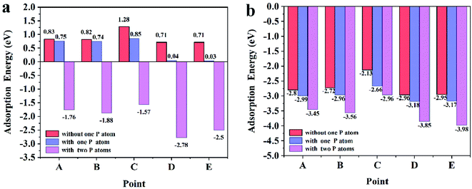 | ||
| Fig. 2 (a) The adsorption energies of the sodium on the points A–E; (b) the adsorption energies of the lithium on the points A–E. | ||
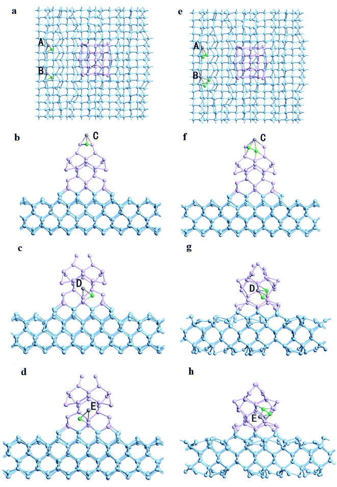 | ||
| Fig. 3 Li/Na adsorbs on Ge nanowires on top of Ge substrates modified by one P atom (a–d) and two P atoms (e–h). The green ball represents P atom. | ||
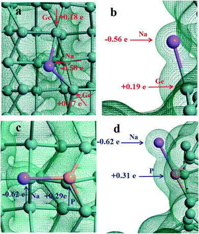
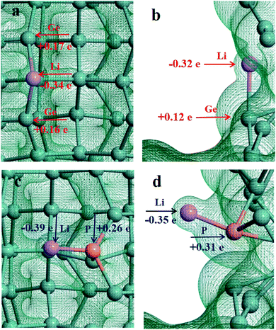
In order to understand the adsorption nature of Li and Na on the Ge nanowires on top of Ge substrates, the three-dimensional charge density is shown in Fig. 4 and 5, and the partial charge was calculated by Mulliken population analysis. It can be visualized that there is electron density between Na and Ge at position B, evidencing the existence of Na–Ge bond. During adsorption process, Na loses 0.58e and two adjacent Ge atoms get 0.18e and 0.17e, as shown in Fig. 4a. After P modification, Na loses more electron to 0.62e while P gets 0.29e, as seen in Fig. 4c. Similarly, Fig. 4b and d show that in the process of bonding between Na and Ge at position D, Na loses 0.56e and Ge gets 0.19e. With P decoration, Na loses 0.62e while P gets 0.31e. In combination with the adsorption energy of points B and D in Fig. 2a, it can be found that Na loses more electron after the addition of P, resulting in a lower adsorption energy. For comparison, Fig. 5a–d shows the bonding and electron transfer of Li adsorbed on the Ge NW with substrate at corresponding positions. In Fig. 5a and c, Li loses 0.34e and Ge atoms obtain 0.16e and 0.17e respectively; after adding a P atom, Li loses more electron to 0.39e, and P gets 0.26e. Moreover, it can be found in Fig. 5b and d that Li loses 0.32e and Ge atoms obtain 0.12e; while after P modification Li loses 0.35e and P gets 0.31e. Similarly, after decoration by a P atom, the electron lost by lithium increases and the adsorption energy decreases, as shown in Fig. 2b. It can be concluded that the interaction between Na/Li and Ge nanowires becomes stronger after P modification which is in accordance with the variation of adsorption energy. Properly increasing the number of P atoms will enhance the interaction between Li/Na and Ge nanowire on top of Ge substrate.
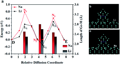
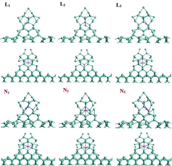
Furthermore, the nudged elastic band (NEB) method was used to study the diffusion pathway and the diffusion energy barriers of lithium/sodium atom on Ge model.35,36 First, the migration of Li/Na on Ge substrate was studied. From point A to point B, the energy curve of Li/Na atom is shown in Fig. 6a and the trajectories of diffusion are visualized in Fig. 6b and c. When Li/Na migrates on the Ge substrate from A to B, the whole energy barrier is smaller than 0.44 eV/0.29 eV. Additionally, this work also investigated the diffusion of Li and Na across the Ge NW as shown in Fig. 7. In Fig. 7a, the energy barrier of Li and Na is 0.65 eV and 0.79 eV respectively, which is similar to the activation energy of the crystalline Ge (0.78 eV).17 The diffusion coefficient (D) can be calculated by D = D0![[thin space (1/6-em)]](https://www.rsc.org/images/entities/char_2009.gif) exp(−Eb/kT), where D0 is the pre-exponential factor, Eb is the activation energy, k is the Boltzmann constant and T is the absolute temperature (T = 300 K here). In a certain temperature range, the diffusion coefficient increases with the improvement of the temperature.37,38 In the migration process in Ge, the D0 is ∼8.5 × 10⁻⁴ cm2 s−1 for Na and ∼9.1 × 10⁻³ cm2 s−1 for Li.16,39,40 Thus the calculated diffusion coefficient is ∼4.6 × 10⁻¹⁷ cm2 s−1 for Na, which is completely within the scope of experimental values from 10−17 to 10−8 cm2 s−1.41 The corresponding diffusion coefficient of Li is ∼1.1 × 10⁻¹³ cm2 s−1, which is comparable to the experimental result (∼10−12 cm2 s−1).42 The variations of the average length of the Ge–M bonds (M stands for Li or Na) in the diffusion process are exhibited by the bar chart. Obviously, the average size of the Ge–Na bonds is about 0.19 Å longer than those of the Ge–Li bonds because the radius of the sodium is larger than that of the lithium. Expectedly, both the average lengths of Ge–Li and Ge–Na bonds are inversely proportional to the energies of the system. Fig. 7b and c shows the relevant trajectories and the detailed atomic structures are shown in Fig. 8.
exp(−Eb/kT), where D0 is the pre-exponential factor, Eb is the activation energy, k is the Boltzmann constant and T is the absolute temperature (T = 300 K here). In a certain temperature range, the diffusion coefficient increases with the improvement of the temperature.37,38 In the migration process in Ge, the D0 is ∼8.5 × 10⁻⁴ cm2 s−1 for Na and ∼9.1 × 10⁻³ cm2 s−1 for Li.16,39,40 Thus the calculated diffusion coefficient is ∼4.6 × 10⁻¹⁷ cm2 s−1 for Na, which is completely within the scope of experimental values from 10−17 to 10−8 cm2 s−1.41 The corresponding diffusion coefficient of Li is ∼1.1 × 10⁻¹³ cm2 s−1, which is comparable to the experimental result (∼10−12 cm2 s−1).42 The variations of the average length of the Ge–M bonds (M stands for Li or Na) in the diffusion process are exhibited by the bar chart. Obviously, the average size of the Ge–Na bonds is about 0.19 Å longer than those of the Ge–Li bonds because the radius of the sodium is larger than that of the lithium. Expectedly, both the average lengths of Ge–Li and Ge–Na bonds are inversely proportional to the energies of the system. Fig. 7b and c shows the relevant trajectories and the detailed atomic structures are shown in Fig. 8.
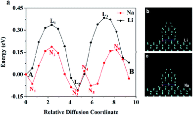 | ||
| Fig. 6 (a) The energy curves for Li/Na diffusion from A to B; the side-view of the trajectories of (b) Li and (c) Na diffusion on the Ge substrate. | ||
Besides, the Li or Na atoms inserted into the Ge nanowires on top of Ge substrates was modeled to investigate the configuration variation in the process of lithiation or sodiation process as visualized in Fig. 9 and 10. After five Li atoms are inserted into the Ge nanowires as shown in Fig. 9a, the height of the Ge nanowire decreases from 12.16 Å to 11.39 Å, while the side length of Ge NW is still around 8.68 Å without any obvious change. Meanwhile, the average length of Ge–Ge bonds changes from 2.53 Å to 2.54 Å. When nine Li atoms are inserted into Ge NW, the relaxed structure is shown in Fig. 9b. The height of Ge NW further decreases to 10.83 Å while the side length of Ge NW is almost unchanged, indicating that the Ge nanowires on top of Ge substrates would keep stable during the lithiation process without obvious volume expansion. The average length of Ge–Ge bonds is 2.56 Å.
 | ||
| Fig. 9 (a) The relaxed structure of the Ge NW with five inserted Li atoms; (b) the relaxed structure of Ge NW with nine inserted Li atoms. | ||
 | ||
| Fig. 10 (a) The relaxed structure of the Ge NW with five inserted Na atoms; (b) the relaxed structure of Ge NW with nine inserted Na atoms. | ||
Fig. 10a shows the relaxed atomic structure after five Na atoms are inserted into the Ge NW. The height of Ge NW reduces to 11.39 Å, while the side length increases to 9.20 Å. After five Na atoms are inserted into the Ge nanowire, some Ge–Ge bonds break and the average length of the Ge–Ge bond increases to 2.55 Å. It can be inferred that certain volume expansion of Ge NW occurs, which is consistent with the theoretical and experimental results.16,43 After nine Na atoms are inserted in the Ge NW and relaxed as shown in Fig. 10b, two independent sodium atoms can be found. The height of Ge NW further reduces to 8.61 Å while the side length increases to 10.56 Å. Meanwhile the average length of Ge–Ge bonds increases to 2.58 Å.
Conclusions
In summary, through DFT calculations, the adsorption, diffusion and insertion of lithium and sodium on the Ge nanowires on top of Ge substrates have been theoretically studied. The results show that lithium and sodium tend to adsorb on the sidewall of Ge NW modified by two P atoms. Then, partial charge was calculated by Mulliken population analysis. We find that after P modification, Li and Na will lose more electron, resulting in a lower adsorption energy. The NEB method is used to calculate the diffusion paths and corresponding energy barriers of Li and Na on the Ge nanowires on top of Ge substrates. In addition, the insertion of sodium atoms into Ge NW would lead to certain volume expansion of the Ge NW while the Ge NW would keep stable during lithiation process. This study will contribute to research the adsorption and diffusion of lithium and sodium on nanowires with substrate and the volume expansion caused by the insertion of lithium/sodium into the nanowires. At the same time, it supplies direction for designing Ge anode in sodium ion batteries.Author contributions
Shaoshuai Gao: writing-original draft, software, visualization; Tingyu Zhao, Dongxu Wang, and Jian Huang: software; Youlin Xiang: resources; Yingjian Yu: conceptualization, methodology, writing-original draft, writing-review & editing, supervision.Conflicts of interest
There are no conflicts to declare.Acknowledgements
This study was financially supported by the National Nature Science Foundation of China (Grant No. 61904073), Yunnan Fundamental Research Projects (No. 2019FGF02), Projects of Science and Technology Plans of Kunming (2019-1-C-25318000002189), Spring City Plan – Special Program for Young Talents (ZX20210014), Scientific Research Fund Project of Yunnan Provincial Department of Education (2020Y0463), and Key Laboratory of Artificial Microstructures in Yunnan Higher Education.References
- P. G. Anselma, P. Kollmeyer, J. Lempert, Z. Zhao, G. Belingardi and A. Emadi, Appl. Energy, 2021, 285, 116440 CrossRef.
- Y. Liu, Z. Huang, J. Li, M. Ye, Y. Zhang and Z. Chen, Appl. Math. Model., 2021, 95, 715–733 CrossRef.
- Y. Zhang, Y. Liu, Y. Huang, Z. Chen, G. Li, W. Hao, G. Cunningham and J. Early, Energy, 2021, 228, 120631 CrossRef.
- Y. Yu, Y. Wang, S. Zhang, P. Zhang, S. Xue, Y. Xie, Z. Zhou, J. Li and J. Kang, Nano Energy, 2019, 61, 604–610 CrossRef CAS.
- Y. Yu and S. Hu, Chin. Chem. Lett., 2021, 32, 3277–3287 CrossRef CAS.
- K. M. Abraham, ACS Energy Lett., 2020, 5, 3544–3547 CrossRef CAS.
- K. Chayambuka, G. Mulder, D. L. Danilo and P. H. L. Notten, Adv. Energy Mater., 2020, 10, 2001310 CrossRef CAS.
- T. Wang, D. Legut, Y. Fan, J. Qin, X. Li and Q. Zhang, Nano Lett., 2020, 20, 6199–6205 CrossRef CAS PubMed.
- C. Wei, S. Guo, W. Ma, S. Mei, B. Xiang and B. Gao, Chin. J. Rare Met., 2021, 45, 611–631 Search PubMed.
- L. Baggetto, J. K. Keum, J. F. Browning and G. M. Veith, Electrochem. Commun., 2013, 34, 41–44 CrossRef CAS.
- T. Zeng, H. He, H. Guan, R. Yuan, X. Liu and C. Zhang, Angew. Chem., Int. Ed., 2021, 60, 12103–12108 CrossRef CAS PubMed.
- J. Liu, S. Muhammad, Z. Wei, J. Zhu and X. Duan, Nanotechnology, 2020, 31, 015402 CrossRef CAS PubMed.
- H. Shen, Z. Ma, B. Yang, B. Guo, Y. Lyu, P. Wang, H. Yang, Q. Li, H. Wang and Z. Liu, J. Power Sources, 2019, 433, 126682 CrossRef CAS.
- K. C. Wasalathilake, N. Hu, S. Fu, J. Zheng, A. Du and C. Yan, Appl. Surf. Sci., 2021, 536, 147779 CrossRef CAS.
- K. Tseng, S. Huang, W. Chang and H. Tuan, Chem. Mater., 2018, 30, 4440–4447 CrossRef CAS.
- S. C. Jung, H. Kim, Y. Kang and Y. Han, J. Alloys Compd., 2016, 688, 158–163 CrossRef CAS.
- C. Chou, M. Lee and G. S. Hwang, J. Phys. Chem. C, 2015, 119, 14843–14850 CrossRef CAS.
- P. R. Abel, Y. Lin, T. Souza, C. Chou, A. Gupta, J. B. Goodenough, G. S. Hwang, A. Heller and C. B. Mullins, J. Phys. Chem. C, 2013, 117, 18885–18890 CrossRef CAS.
- A. Kohandehghan, K. Cui, M. Kupsta, J. Ding, E. M. Lotfabad, W. P. Kalisvaart and D. Mitlin, Nano Lett., 2014, 14, 5873–5882 CrossRef CAS PubMed.
- Q. Wang, C. Zhao, Y. Lu, Y. Li, Y. Zheng, Y. Qi, X. Rong, L. Jiang, X. Qi, Y. Shao, D. Pan, B. Li, Y. Hu and L. Chen, Small, 2017, 13, 1701835 CrossRef PubMed.
- Y. Yu, S. Hu and J. Huang, Mater. Chem. Phys., 2020, 253, 123243 CrossRef CAS.
- Y. Yu, S. Hu and J. Huang, J. Phys. Chem. Solids, 2021, 157, 110226 CrossRef CAS.
- Y. Yu, S. Gao and S. Hu, J. Alloys Compd., 2021, 883, 160902 CrossRef CAS.
- S. Hu, Y. Yu, Y. Guan, Y. Li, B. Wang and M. Zhu, Chin. Chem. Lett., 2020, 31, 2839–2842 CrossRef CAS.
- Y. Yu, D. Chen, S. Gao, J. Huang, S. Hu, H. Yang and G. Jin, RSC Adv., 2019, 9, 39582–39588 RSC.
- J. P. Perdew, K. Burke and M. Ernzerhof, Phys. Rev. Lett., 1996, 77, 3865–3868 CrossRef CAS PubMed.
- A. Kakanakova-Georgieva, G. K. Gueorguiev, S. Stafstrom, L. Hultman and E. Janzen, Chem. Phys. Lett., 2006, 431, 346–351 CrossRef CAS.
- S. A. Khan, D. Senapathi, T. Senapathi, M. S. Liao, P. Bonifassi, Z. Fan, A. K. Singh, A. Neeley, G. Hill, M. J. Huang, J. D. Watts and P. C. Ray, Chem. Phys. Lett., 2011, 516, 62–67 CrossRef.
- R. B. Santos, R. Rivelino, F. B. Mota, G. K. Gueorguiev and A. Kakanakova-Georgieva, J. Phys. D: Appl. Phys., 2015, 48, 295104 CrossRef.
- P. K. Nayak, L. Yang, W. Brehm and P. Adelhelm, Angew. Chem., Int. Ed., 2018, 57, 102–120 CrossRef CAS PubMed.
- M. Seo, M. Park, K. T. Lee, K. Kim, J. Kim and J. Cho, Energy Environ. Sci., 2011, 4, 425–428 RSC.
- G. Lee, M. Sung, Y. S. Kim, B. Ju and D. Kim, ACS Nano, 2020, 14, 15894–15903 CrossRef PubMed.
- Y. Ko, J. Kang, G. Lee, J. Park, K. Park, Y. Jin and D. Kim, Nanoscale, 2011, 3, 3371–3375 RSC.
- Y. Sun, F. Zeng, Y. Zhu, P. Lu and D. Yang, J. Energy Chem., 2021, 61, 531–552 CrossRef.
- G. Mills, H. Jonsson and G. K. Schenter, Surf. Sci., 1995, 324, 305–337 CrossRef CAS.
- S. Smidstrup, A. Pedersen, K. Stokbro and H. Jonsson, J. Chem. Phys., 2014, 140, 214106 CrossRef PubMed.
- M. Schwaab and J. C. Pinto, Chem. Eng. Sci., 2007, 62, 2750–2764 CrossRef CAS.
- I. I. Fabrikant and H. Hotop, J. Chem. Phys., 2008, 128, 124308 CrossRef PubMed.
- L. C. Loaiza, L. Monconduit and V. Seznec, Small, 2020, 16, 1905260 CrossRef CAS.
- A. H. Sher, J. Appl. Phys., 1969, 40, 2600–2607 CrossRef CAS.
- R. Kohli and K. L. Mittal, Developments in Surface Contamination and Cleaning: Types of Contamination and Contamination Resources, Elsevier, 2017 Search PubMed.
- B. Laforge, L. Levan-Jodin, R. Salot and A. Billard, J. Electrochem. Soc., 2008, 155, A181–A188 CrossRef CAS.
- X. Lu, E. R. Adkins, Y. He, L. Zhong, L. Luo, S. X. Mao, C. Wang and B. A. Korgel, Chem. Mater., 2016, 28, 1236–1242 CrossRef CAS.
| This journal is © The Royal Society of Chemistry 2022 |


