
 Open Access Article
 This Open Access Article is licensed under a Creative Commons Attribution-Non Commercial 3.0 Unported Licence
Preparation and characterization of a novel drug-loaded Bi-layer scaffold for cartilage regeneration†
Yunqing Yue,
Peihu Xu*,
Zhixin Lei,
Kebi Li,
Jingyi Xu,
Jing Wen,
Sining Wang,
Wanting Cheng,
Sihui Lin,
Zhijun Huang and
Haixing Xu *
*
Department of Pharmaceutical Engineering, School of Chemistry, Chemical Engineering and Life Science, Wuhan University of Technology, 430070, China. E-mail: Whutxph68@126.com; xhx040328@whut.edu.cn
First published on 25th March 2022
Abstract
The incidence of articular cartilage defects is increasing year by year. In order to repair the cartilage tissue at the defect, scaffolds with nanofiber structure and biocompatibility have become a research hotspot. In this study, we designed and fabricated a bi-layer scaffold prepared from an upper layer of drug-dispersed gelatin methacrylate (GELMA) hydrogel and a lower layer of a drug-encapsulated coaxial fiber scaffold prepared from silk fiber (SF) and polylactic acid (PLA). These bi-layer scaffolds have porosity (91.26 ± 3.94%) sufficient to support material exchange and pore size suitable for cell culture and infiltration, as well as mechanical properties (2.65 ± 0.31 MPa) that meet the requirements of cartilage tissue engineering. The coaxial fiber structure exhibited excellent drug release properties, maintaining drug release for 14 days in PBS. In vitro experiments indicated that the scaffolds were not toxic to cells and were amenable to chondrocyte migration. Notably, the growth of cells in a bi-layer scaffold presented two states. In the hydrogel layer, cells grow through interconnected pores and take on a connective tissue-like shape. In the coaxial fiber layer, cells grow on the surface of the coaxial fiber mats and appeared tablet-like. This is similar to the structure of the functional partitions of natural cartilage tissue. Together, the bi-layer scaffold can play a positive role in cartilage regeneration, which could be a potential therapeutic choice to solve the current problems of clinical cartilage repair.
1. Introduction
Articular cartilage is a layer of connective tissue encased in the surface of the joint, which has the function of bearing mechanical load, lubricating the joint, maximizing absorption, buffering stress, etc.1,2 In cases of acute trauma and chronic wear, articular cartilage will suffer from varying degrees of damage, often causing joint pain, limited mobility, and even loss of function.3–5 Due to the low degree of vascularization, the nutrition of cartilage tissue mainly comes from the joint fluid, and its ability to regenerate is very limited if a traumatic or pathological event occurs.6,7 Currently, the methods used to treat cartilage defects include surgeries contain microfractures, autologous osteochondral transplantation, and autologous chondrocyte implantation.8–10 These treatments can improve some of the symptoms, but some adverse reactions are reported.11,12 In recent years, tissue engineering (TE) has made considerable progress in obtaining functional articular cartilage. However, currently popular tissue engineering methods are difficult to restore damaged sites to their normal state because of their limited ability to rebuild anisotropic structures in native cartilage tissue.13–16 Natural cartilage tissue consists of several continuous but different regions, which have spatial variability in fiber structure and mechanical properties. For example, collagen fibers are parallel to the articular surface in the superficial regions of the articular cartilage and even perpendicular to the articular surface in the deep regions.2,3,17 Therefore, the ideal biological material should have the ability to rebuild three-dimensional tissue and have the structure of mimicking natural cartilage tissue.At present, the main materials of scaffolds used in cartilage tissue engineering include inorganic materials, ECM-based materials, metals, and composite materials of the above-mentioned materials.18 Among them, PLA is a biodegradable composite with high mechanical strength and biocompatibility, so it is usually used as the preferred material for biological scaffolds.19–21 Due to the large brittleness at normal temperature, low fracture elongation and poor hydrophilicity, PLA is currently mixed with other natural materials to improve its related properties.22 Natural polymers have been extensively explored due to their structural similarity and biocompatibility with natural GAGs.23–30 Silk is the only natural fiber that exists in the form of continuous filaments, and this unique advantage contributes to the diversity of silk fiber applications.31,32 The mixing of silk fiber and PLA can make up for the problem of poor hydrophilicity of PLA and large brittleness at normal temperature. Another popular protein natural polymer worth mentioning for cartilage repair is collagen. Collagen is the main protein component constituting the ECM, and its derivative, gelatin, has attracted much attention due to its excellent properties. Additionally, gelatin has been classified as Generally Recognized as Safe by the U.S. Food and Drug Administration (US FDA). The molecular structure of gelatin contains many parts that form hydrogen bonds, such as carboxyl (–COOH), amine (–NH2) and hydroxyl (–OH), so it is an excellent natural material.33–35
Since many factors are involved in the process of cartilage repair, different drugs can positively affect cartilage repair in different ways during treatment. Among them, inhibiting the inflammatory response in cartilage defects and promoting the transformation of stem cells into chondrocytes have been proved to be two important ways.36,37 With the deepening of research, the combined use of drugs proved to be an effective strategy to promote cartilage repair.38,39 Therefore, it is necessary to simultaneously inhibit the inflammatory response in cartilage defects and promote the transformation of stem cells to chondrocytes to promote cartilage repair through the synergistic effect of drugs. Sodium aescinate is a triterpenoid saponin sodium salt extracted from the dried and ripe fruit of Aesculus chinensis. Recent studies have shown that sodium aescinate can significantly inhibit the inflammatory response of cells by inhibiting the NF-κB pathway and up-regulating the expression of TGF-β1.40,41 Kartogenin is a small molecule compound first discovered by Johnson et al. in 2012, which could enhance chondrogenic differentiation of human mesenchymal stem cells (hMSCs).42 KGN binds filamin A, disrupting its interaction with the transcription factor core binding factor beta subunit (CBFB) and inducing cartilage formation by regulating the CBFB-Runx1 transcription program.43
The purpose of this study was to exploit multifunctionality of several materials to product a bi-layer scaffold for functional cartilage tissue engineering. Although electrospinning materials have been successfully developed in the field of neural tissue engineering, they have not yet been applied to a cartilage system. Coaxial fibers and light-cured hydrogels have been combined for the first time to product cartilage TE scaffolds. The bi-layer scaffold was evaluated according to mechanical properties and drug release properties. The correlation of bi-layer scaffolds and cell co-culture was employed to test the hypothesis whether the scaffolds exhibited similar properties to native cartilage tissue and whether cartilage constructs that mimic native cartilage could be generated after in vitro culture. Through this work, we propose the design of a novel cartilage scaffold with the ability to generate cartilage constructs close to the properties of native cartilage, which provides new ideas for cartilage defect repair.
2. Materials and methods
2.1 Materials
Poly lactic acid (Shanghai Hushi Laboratorial Equipment Co., Ltd, China), silk fibroin (Beijing Sinolactide Medical Technology Co., China); gelatins (Shanghai Hushi Laboratorial Equipment Co., Ltd, China), kartogenin (APExBIO Technology LLC, America), sodium aescinate (Shandong Lvye Pharmaceutical Co.,Ltd, China), methacrylic anhydride and lithium phenyl(2,4,6-trimethylbenzoyl)phosphinate (Shanghai Macklin Biochemical Co., Ltd, America), Dulbecco's modified eagle medium/nutrient mixture F-12, penicillin/streptomycin solution and fetal bovine serum (Thermo Fisher Scientific (China) Co., Ltd, America), 0.25% trypsin, CCK-8 tests fit and DAPI solution, (Sangon Biotech (Shanghai) Co., Ltd, America), DiI solution (Shanghai Yuanye Bio-Technology Co., Ltd, China), Triton X-100 (Beyotime Biotech Inc., China), 4% paraformaldehyde and 2.5% glutaraldehyde solution (Shanghai Hushi Laboratorial Equipment Co., Ltd, China).2.2 Preparation of SF/PLA coaxial fiber mats
The coaxial fiber mats were prepared using the method described in studies,44,45 albeit with slight modifications.First, a shell electrospinning solution was prepared by successively dissolving 0.3 g of SF in 10 g of 1,1,1,3,3,3-hexafluoroisopropanol (HFIP). Second, the core solution was prepared by dissolving PLA (7% w/v) and KGN (0.2% w/v) in dichloromethane (DCM). After magnetic stirring at 25 °C for 12 h, all electrospinning solutions were sonicated at 42.5 kHz for 2 h and then stored at 25 °C until further processing.
The two electrospinning solutions were aspirated into two different syringes (10 mL each), respectively. Then syringes were subsequently fixed to the electrospinning system (Elite electrospinning equipment, ET2016, Beijing Yongkang Le Ye Technology Development Co., Ltd, China). The conditions of the coaxial electrospinning system were as follows: the injection rate of the core and shell electrospinning solution was 0.15 mm min−1, the model of the coaxial needle was 18 G/26 G, the positive and negative voltages were 15.61 and −3.29 kV, respectively, and a receiving distance of 15 cm at 25 °C. During the experiment, the indoor humidity was kept at 40%. A series of sample mats with drug loading were fabricated. The resulting mats were further dried in a vacuum oven at 40 °C for 12 h to remove the residual organic solvent.
2.3 Preparation of bi-layer scaffold
![[thin space (1/6-em)]](https://www.rsc.org/images/entities/char_2009.gif) :0.6 (v/v). The reaction was stopped by adding enough deionized water. The reactor solution was used in dialysis tubes (12–14 kDa) for 1 week with ultrapure water at 40 °C to remove excess methyl acrylic. Finally, the resulting solution was freeze-dried at −120 °C and stored in the dark environment for further use.
:0.6 (v/v). The reaction was stopped by adding enough deionized water. The reactor solution was used in dialysis tubes (12–14 kDa) for 1 week with ultrapure water at 40 °C to remove excess methyl acrylic. Finally, the resulting solution was freeze-dried at −120 °C and stored in the dark environment for further use.The fabrication process of the entire scaffold was shown in Fig. 1. Briefly, small rectangular strips (length = 20 cm; width = 5 mm) were cut from the electrospinning mat prepared in 2.2, then rolled into helical cylinders and placed in Teflon molds (diameter = 1 cm). The 0.5 mL of the hydrogel precursor solution was injected into it. We irradiated UV light (365 nm) for 10 seconds from above the mold to fully crosslink the hydrogel layer.
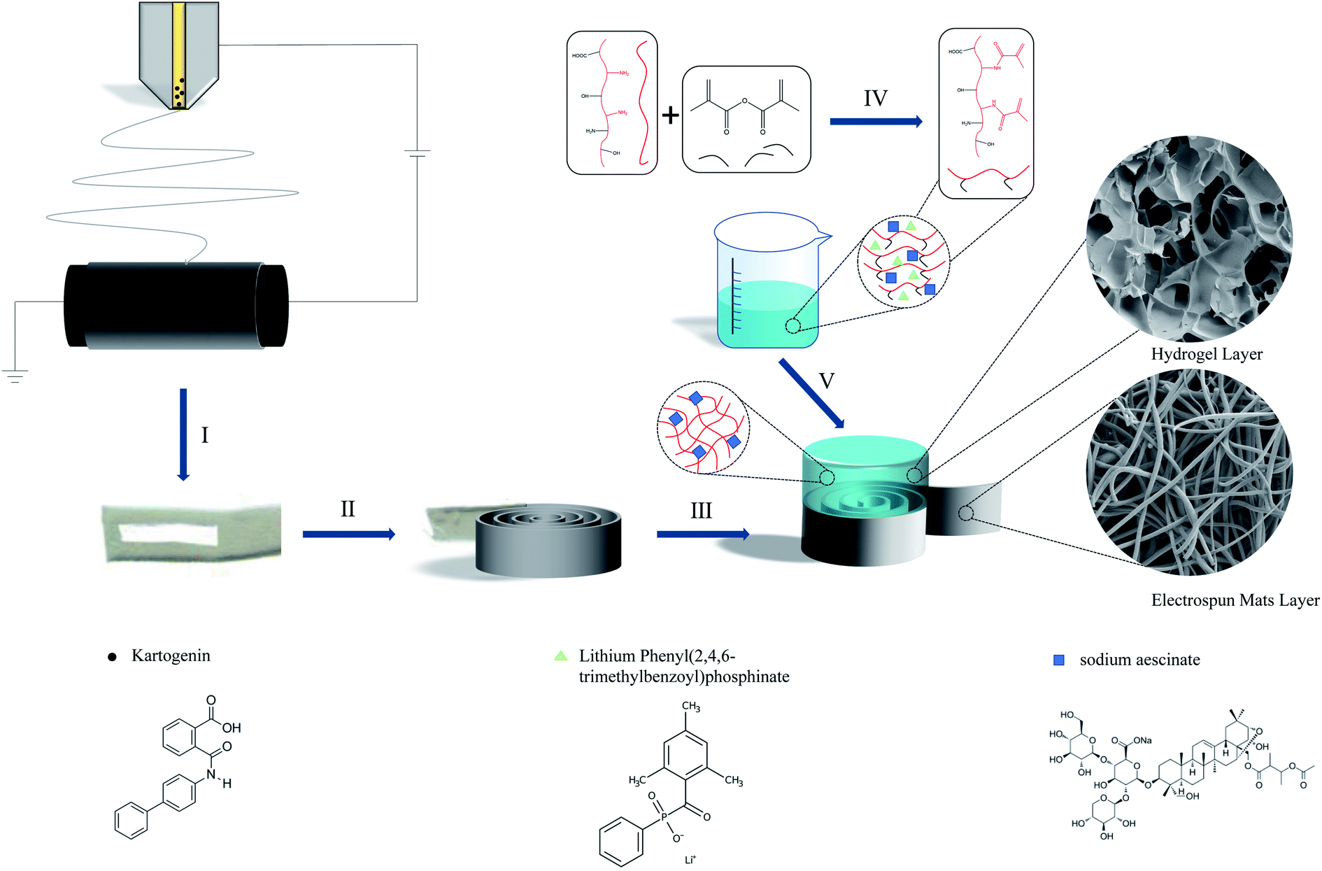 | ||
| Fig. 1 Schematic of the fabrication of the bi-layer scaffold: (I) electrospinning onto a rotating drum; (II) cutting cylinders from the electrospun mats for building the lower layer; (III) rolling a small rectangle from the electrospun mats; (IV) 10% w/v gelatin was reacted with ma in a solution in deionized water at 50 °C; (V) hydrogel precursor solution was UV-crosslinked to leave unreacted free-radicals available for chemical binding with the higher layer hydrogel. | ||
Finally, the obtained bi-layer scaffold was frozen in a −80 °C refrigerator for 24 hours. The bi-layer scaffolds were taken out after being fully frozen, and freeze-dried at −100 °C for 12 hours to obtain the finished product.
2.4 Characterizations

The formula of porosity (%) was as follows:

where W0 and Wt represent the initial weight at drying and the weight obtained after different swelling times, respectively.

2.5 In vitro release testing
The release experiments of KGN were carried out in 5 mL tubes. The scaffolds were placed in test tubes, 3 mL of PBS solution (pH = 7.4) was added and the tubes were placed in a constant temperature shaker at 37 °C. At each time point (1, 2, 3, 4, 6, 8, 10, 13, 16, 19 days), 1 mL of release solution was extracted from the tube and replaced with fresh PBS solution (n = 6). The concentration of the drug solution was determined by HPLC (High Performance Liquid Chromatography, e2695-2489, Waters, America). The formula for the cumulative release rate of KGN was as follows:where Wi represented the cumulative release of KGN at different times, and W0 represented the total load of KGN in the scaffold.

The release rate experiments of SA were like those of KGN. Briefly, the scaffold was placed in a centrifuge tube, and 3 mL of PBS solution (pH = 7.4) was added. The tubes were placed in a constant temperature shaker at 37 °C. At each time point, the 1 mL of release solution was collected from the tube and replaced with fresh PBS (n = 6). The concentration of the drug solution was determined by UVs (Ultraviolet-visible Spectrophotometer, UV2600, Shimadzu, Japan). The formula for the cumulative release rate of SA was as follows:

2.6 Cytotoxicity assay and cell adhesion
The cytocompatibility of scaffolds was evaluated by cytotoxicity assay. The experimental groups of cytocompatibility were as follows: GELMA group, GELMA/SA group, SF/PLA group, SF/PLA/KGN group, bi-layer scaffold group and the blank control group. The scaffolds were placed in 24-well plates and sterilized, soaked in culture medium for 24 h.In this study, we used the CCK-8 assay to detect cytotoxicity. The specific procedure was as follows: in an incubator (37 °C, 5% CO2), the annulus fibrosus cells were grown in the medium (Dulbecco's modified eagle medium/nutrient mixture F-12 containing 1% penicillin/streptomycin solution and 20% fetal bovine serum) and passed 2–3 generations wait for use. The passaged cells were digested with trypsin and shook, diluted to add 100 μL of cell suspension to each well of the plate with a concentration of 1 × 10⁵ cells per mL. Each group contained 6 replicate wells. The toxicity tests were performed on the day 1, day 3, and day 5, respectively. At each time point, the original medium was replaced with fresh medium containing 10% CCK-8 solution, and incubated for 2 h. After the end, the absorbance of each well was detected with an enzyme-labeled instrument.
Annulus fibrosus cells were inoculated on the scaffold at a density of 1 × 10⁵ cells per mL and cultured in an incubator (37 °C, 5% CO2). Five days later, cells in the scaffold were immobilized with 4% paraformaldehyde for 30 minutes, followed by 0.1% Triton X-100 for 15 minutes to increase cell permeability. Subsequently, cell membranes were stained with DiI and nuclei were stained with DAPI for 30 minutes, respectively. Finally, the morphology of the annulus fibrosus cells in the scaffold was observed and photographed under FIM (fluorescence inverted microscope, Leica, Germany).
After 5 days of culture, the cells on the nails were fixed with 2.5% glutaraldehyde solution for 30 min, and then dehydrated with ethanol and isoamyl acetate. After critical point drying, the growth morphology of chondrocytes was observed by SEM.
2.7 Statistical analysis
All quantitative data in this paper were expressed as means ± standard deviation. Statistical analyses were performed with one-way analysis of variance (ANOVA) and post hoc tests. The significant difference levels between groups were set as *P < 0.05 and **P < 0.01.3. Results
3.1 Scaffolds morphology
In this study, the process of preparing the bi-layer scaffolds were illustrated in Fig. 1. The Fig. 2A and B showed that the bi-layer scaffold consisted of a GELMA layer of about 5 mm in the upper part and a coaxial fiber layer of about 5 mm of in the lower part, which was forming a layered structure similar to cartilage tissue. As shown in the Fig. 2C, the two layers could be well integrated into a single structure, with clear boundaries between the hydrogel and fiber layers. The porosity of both the fiber layer and the hydrogel layer was greater than 80% (94.84 ± 3.72% for fiber layer and 85.93 ± 4.81% for hydrogel layer) and the porosity of the bi-layer scaffold was 91.26 ± 3.94%. | ||
| Fig. 2 (A and B) The appearance of the scaffold; (C) the SEM of vertical cut of the scaffold; (D) the SEM of spiral structure of the electrospinning mats layer; (E and F) the SEM of hydrogel layer (200 μm, 30 μm); (G) the SEM of electrospinning mats layer; (H) the tem of coxical fiber. | ||
The SEM image showed the construction of the fiber layer scaffold in Fig. 2D and G. In the fiber layer, the thickness of coaxial fiber mats was about 100 μm and the gap between mats was 20–40 μm. Simultaneously, the construction of the coaxial fibers was visualized through TEM. As shown in Fig. 2H, the coaxial fibers were highly aligned with a mean diameter of 269 ± 24 nm and the core fibers were with a mean diameter of 115 ± 10 nm. The SEM image showed the construction of the hydrogel layer scaffold in Fig. 2E and F. The GELMA hydrogels had a continuous network structure and the diameter of pore of hydrogels was mostly 100 μm as illustrated in Table 1.
| Scaffold type | Mean pore size | Porosity (%) |
|---|---|---|
| GelMA | 103.55 ± 11.7 (μm) | 85.93 ± 4.84 |
| Coaxial fiber | 256.32 ± 25.1 (nm) | 94.84 ± 3.72 |
| Bi-layer scaffold | — | 91.26 ± 3.94 |
3.2 Mechanical properties
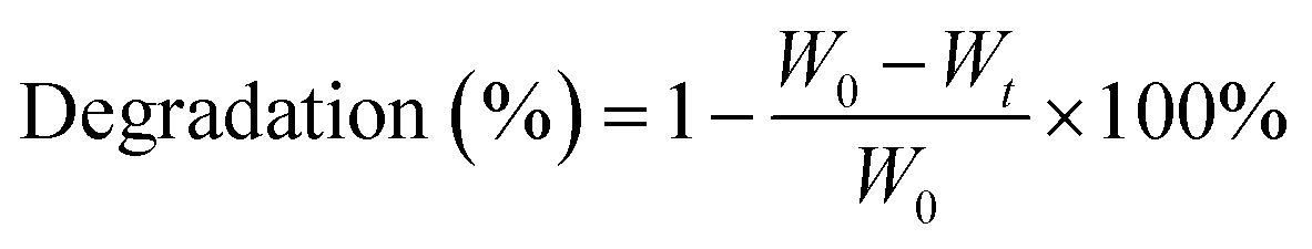
The compressive modulus was shown for the GELMA hydrogels, SF/PLA coaxial fibers mats and corresponding bi-layer scaffold composites in Fig. 3A. Compared to pure hydrogels, the bi-layer scaffold exhibited enhanced load bearing capacities (P < 0.01). The compressive modulus of hydrogel layer (196.7 ± 5.3 kPa) was remarkably low compared with that of human articular cartilage (≈1 MPa). The compressed modulus of the fiber layer reaches 6.11 ± 0.62 MPa, but the deformation that is brought to the fiber layer is irreversible. Noticeably, compressive modulus was increased by up to 10-times (2.65 ± 0.31 MPa) in the bi-layer scaffold construct, reached a level comparable to that of native cartilage.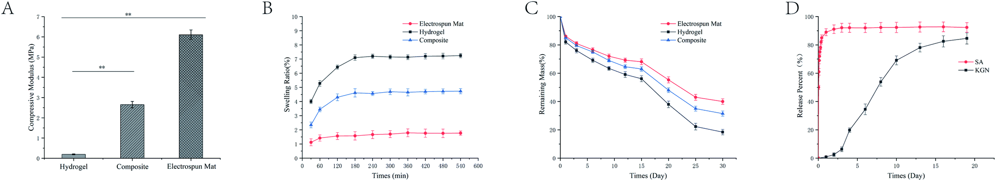 | ||
| Fig. 3 (A) The compressive modulus of bi-layer scaffold with different layers (**P < 0.01); (B) the swelling curve of the scaffold; (C) the remaining mass of bi-layer scaffold with different layers, (D) the cumulative release rate of drugs from bi-layer scaffold. | ||
Meanwhile, the swelling behaviour of various hydrogels is shown in Fig. 3B. The swelling ratio of the monolayer hydrogel was 7.10 ± 0.18 about 4 times that of the fiber layer (1.77 ± 0.24). The swelling ratio of the overall scaffold was 4.73 ± 0.22. The degradation profiles of the bi-layer scaffold were further monitored and shown in Fig. 3C. At the end of 30 days, the remaining mass rate of GELMA hydrogel reached to 18.4 ± 1.9%. With the addition of coaxial fibers, the remaining mass rate of the bi-layer scaffold was 31.5 ± 1.8%. During degradation profiles, the pH of each material group remained virtually unchanged.
3.3 Drug release
The release of drugs from the different combined methods was investigated by immersion experiments. The SA combined by electrostatic adsorption showed an initial drug release of 72.1 ± 2.94% within 1 h, followed by a rapid release until 24 h, and the cumulative release rate reached 50 in 1 d. In contrast with SA, the KGN of coaxial fibers showed a 70 times lower release within 1 d. The coaxial fibers showed an initial drug release of 0.9 ± 0.14% within 12 h, followed by a fast release until 4 d and a steady release from 3 d to 8 d dominated by drug diffusion. Subsequently, another phase of rapid release could be detected from 8 d to 16 d, which resulted in almost completed release after 16 d (82.5 ± 3.94%, Fig. 3D).3.4 Cell cytotoxicity
After culturing the cells for 3 days, the OD values of each groups increased, indicating that the micro environment provided by scaffold were suitable for cell growth and proliferation (Fig. 4A). On the first day, the OD values for each group were almost identical, with no obvious difference. After the 3 days of culture, the OD values of the experimental groups were all higher than the control group and the OD value of cells in the bi-layer scaffold group was higher than that in the other groups (*P < 0.05). The activity of the cells was not affected as the drug was introduced into the material. | ||
| Fig. 4 (A) The OD values of annulus fibrosus cells cultured in the presence of each group of materials after 1 day, 3 days and 5 days in culture (*P < 0.05). (B) The DiI and DAPI fluorescence staining of annulus fibrosus cells cultured with materials for 5 days. the scale bar is 50 μm. | ||
The DAPI (nucleus, blue) and DiI (cell membrane, red) fluorescent staining of annulus fibrosus cells cultured with material leachate for 5 days was shown in the Fig. 4B. In the control group, the cells had grown from their original circles to spindles with small numbers of axons, but in smaller quantities and slower growth. For the bi-layer scaffold groups and the SF/PLA/KGN groups, the number of the cells were obviously more than other groups. The cells became denser and had contacted with each other to form larger aggregates on the scaffolds, which indicated the presence of ECM. The visible axons of cells in the hydrogel groups had grown longer, indicating that the release of KGN facilitated the growth of the annulus fibrosus cells.
3.5 Morphology and distribution of cells in bi-layer scaffolds
The Fig. 5C and D presented the SEM images of annulus fibrosus cells which were seeded on the bi-layer scaffolds. The cells in the scaffold could be identified as marked by the white arrows. In Fig. 5D, the annulus fibrosus cells, attached to the walls of holes, are randomly distributed in the holes of the hydrogel layer. In contrast, the Fig. 5C presented that cell grow on the surface of the coaxial fiber mats (removed the coaxial fibers layer). Furthermore, we observed denser cell numbers and morphology on the coaxial fiber layer compared to the hydrogel layer, which is consistent with the results of the cytotoxicity assay.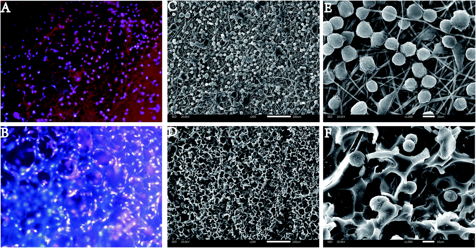 | ||
| Fig. 5 The FIM images of chondrocytes morphology on the electrospinning mats layer (A) and hydrogel layer (B) after culture for 5 days; the SEM images of chondrocytes morphology on the electrospinning mats layer (C) and hydrogel layer (D) after culture for 5 days (200× magnification); the SEM images of chondrocytes morphology on the electrospinning mats layer (E) and hydrogel layer (F) after culture for 5 days (1000× magnification). | ||
Due to the light transmission properties of the hydrogel, we could observe lots of cells dispersed inside the hydrogel layer in Fig. 5B, which was consistent with Fig. 5D. In Fig. 5A, cells had grown to a spindle shape with lots of axons, and all cells grew along the coaxial fiber mats, which is consistent with Fig. 5C.
4. Discussion
The aim of this study was to design a new bi-layer scaffold for cartilage repair and to investigate the effect of scaffold on the response of seeded cells in vitro. The results showed that bi-layer scaffold had higher porosity, and these scaffolds were able to stimulate cells to exhibit higher levels of growth. Previous studies have shown that the presence of KGN significantly promotes chondrogenesis and chondrocyte proliferation,47,48 which is consist scaffold with our experimental results. After the day 5 of culture, the OD values of the experimental groups were all higher than the control group, and the OD value of cells in the bi-layer scaffold group was significantly higher than that of the control groups (*P < 0.05). In the Fig. 4B, the number of the cells were significantly more than other groups. The cells in the bilayer scaffold group contacted each other to form larger aggregates, indicating that there was already a tendency to generate ECM.Morphologically, the porosity of fiber layer scaffold was lower than hydrogel layer, which was due to the smaller fiber diameter (269 ± 24 nm). Higher porosity led to an easy exchange of substances, which is beneficial for cell growth.49,50 Therefore, cartilage regeneration required multidimensional regulation of the joint microenvironment in space and time, which was very important for the quality of cartilage tissue after regeneration.36 According to Kap-Soo Han et al., scaffolds with pores of 50–180 μm and a porosity of 60–80% are most favorable for chondrocyte proliferation.51 But interestingly, scaffolds with higher than 90% porosity still promoted chondrocyte growth. As illustrated in Fig. 5C and D, cells grew much denser on fiber layer than cells in hydrogel layer. Due to the introduction of coaxial fibers, the compressive modulus of the bi-layer scaffold (2.65 ± 0.31 MPa) was ten times that of the hydrogel. On the one hand, the introduction of PLA in the scaffold system changed the mechanical properties of the scaffold. On the other hand, the structural design of the bi-layer scaffold played a key role in the change of the compressive modulus of the bracket. At present, clinical cartilage repair surgery often brought a problem that cartilage defect would form a collapse after surgery.52 The main reason for this phenomenon was that the current clinical treatment methods lack guidance for the growth of chondrocytes, so the tissue structure after the repair of cartilage defects was similar to the superficial zone of natural cartilage.53 The radial zone of natural cartilage mainly played a role in mechanics, so the disappearance of this area leads to the collapse of newly formed cartilage tissue under the compression of external forces.52,54,55 In this study, the structure of the fiber layer mimicked the bund radial zone of natural cartilage, which both changed the compressive modulus of the scaffold and has an impact on the growth trend of the cell. From the sight of TE, improving the mechanical properties of scaffolds was beneficial especially for their performance in vivo.56 The mechanical properties of cell matrices or scaffolds had been shown to affect the growth state of cells in vitro.57
The synergistic effect of drugs has been recognized as an effective strategy to assist cartilage repair in recent years.39,58,59 Drugs could be embedded into scaffold by different drug loading techniques such as electrostatic adsorption and coaxial electrospinning etc. The methods for drug incorporation potentially impacted drug distribution and ultimately drug release profiles.60 The drugs wrapped in the core layer of coaxial fibers can be slowly released as degradation behavior progresses.61 At the beginning of scaffold design, we assumed that different drug loading forms could lead to different release rates of the two drugs. The SA showed an initial drug release of 72.1% within 1 h in the Fig. 3D. Because SA was attached to the hydrogel by electrostatic adsorption, the SA quickly fell off the scaffold when scaffold was implanted in the tissue fluid. The rapid release of SA was determined by the method of drug loading. The SA in the scaffold was fixed on the surface of the scaffold by electrostatic adsorption. When the scaffold was immersed in deionized water, the electrostatic force was destroyed, so the SA falls off the scaffold and disperses in the water. In contrast, the release rate of KGN was very slow. Because KGN was embedded in the core layer of the coaxial fiber, the PLA of core layer was less in contact with the tissue fluid, which made the slow rate of release at the beginning of degradation as illustrated in Fig. 3C and D. Started from the day 3, the rate of KGN release begun to slowly accelerate because the silk fiber in the shell layer of the coaxial fiber begun to degrade. With the contact area of the PLA with the interstitial fluid begins to increase, KGN was more easily released into the interstitial fluid. The degradation curve of the scaffold also proved this in the Fig. 3C. On the day 15, the rate of degradation of the scaffold suddenly increased, possibly because the scaffold had changed morphologically during the degradation process. However, KGN had almost reached the maximum release rate by day 15, the sudden increase in degradation rate did not have much impact on the release behavior of KGN. In the early stages of cartilage repair, the inflammatory response could hinder the growth of chondrocytes.18,62,63 Therefore, the rapid release of SA could effectively inhibit the occurrence of early inflammatory responses after cartilage scaffold is implanted in the body. During the slow release process, KGN could be maintained at an effective concentration for a long time and induced stem cells to differentiate into chondrocytes.64 In the Fig. 4B, the result proved that the combination of drugs and artificial timing administration according to the process of tissue repair were conducive to the rapid growth of cells in the damaged area.
Fig. 5 showed the different growth morphologies of cells in the two-layer scaffold. Compared to hydrogel layer, we observed that the amount and morphology of cells on coaxial fiber layer were denser, which was in accordance with the result of cell viability and proliferation as shown in Fig. 4A. This condition could be caused by local concentration differences in release of KGN. The difference in the growth morphology of the cells on the fiber layer and the hydrogel layer was caused by physical factors. The annulus fibrosus cells, attached to the walls of holes, were randomly distributed in the holes of the hydrogel layer. This result might be caused by the porous structure on the surface of the hydrogel material in the Fig. 2E and F. Because of the existence of the three-dimensional structure of the hydrogel, sufficient space was obtained for the metabolism and exchange of substances in cells, which had a positive effect on cell growth and proliferation. In contract, the structural design of fiber layer encouraged the cells to grow vertically in the Fig. 2D and G. The pore size of the coaxial fiber membrane was about 135 nm, which was much smaller than the distance that cells can grow through.65,66 But, the average length of the gaps between the fiber mats was sufficient to support the growth of cells, which leads to the phenomenon of cells growing against the spiral fiber mats. Cells grown along the surface of the fiber mats would eventually form a spiral tissue, which to a certain extent mimicked the shape of the radial zone of natural cartilage. In summary, the different behaviors of cells in the process of in vitro migration and formation of cartilage tissue indicated that the structure of the scaffold plays a role in the type of synthetic cartilage tissue.
5. Conclusion
To sum up, the SF/PLA/GEL composite scaffold is prepared by electrospinning technology and photocurable hydrogel technology, with excellent physical and chemical properties. More importantly, compared with the traditional cartilage repair scaffold, the bi-layer scaffold in this study provides good cell adhesion, vitality, and proliferation due to the presence of natural materials in the coaxial fiber structure. Through the structural design of the bi-layer scaffold, it provides the possibility to achieve the repair goal of the functional structure of natural cartilage tissue. While the results show that the bi-layer scaffold has a good application prospect in the surgical application of articular cartilage, additional studies must be conducted to better tune the degradation rate of the scaffold to align with the cartilage growth rate. Future work will focus on the internal integrity of cartilage regeneration and the personalization of cartilage tissue repair for different individuals and different parts.Author contributions
Yunqing Yue: conceptualization, methodology, investigation, writing – original draft. Zhixin Lei, Zhijun Huang: supervision, validation, writing – review & editing. Kebi Li, Jingyi Xu, Jing Wen, Sining Wang, Wanting Cheng, Sihui Lin: participating in experiments. Peihu Xu: writing – review & editing. Haixing Xu: supervision, funding acquisition, validation.Conflicts of interest
The authors declare that they have no known competing financial interests or personal relationships that could have appeared to influence the work reported in this paper.Acknowledgements
The financial support from the National Natural Science Foundation of China (No: 51572206), Wuhan Huanghe Excellence Plan, National Innovation and Entrepreneurship Training Program for College Students (No: 202110497032, 202110497033, S202110497080, 2022104970183, 2022104970186 and 2022104970203) and the Fundamental Research Funds for the Central Universities (WUT: 2021IUA075) are kindly acknowledged.Notes and references
- K. S. Emanuel, L. Kellner, M. J. M. Peters, M. J. J. Haartmans, M. T. Hooijmans and P. J. Emans, Osteoarthr. Cartil., 2021 DOI:10.1016/j.joca.2021.10.016.
- Z. Wu, S. H. Korntner, A. M. Mullen and D. I. Zeugolis, Biomaterials and Biosystems, 2021 DOI:10.1016/j.bbiosy.2021.100030.
- T. Stampoultzis, P. Karami and D. P. Pioletti, Curr. Res. Transl. Med., 2021, 69, 103299 CrossRef PubMed.
- T. Totlis, T. Marin Fermin, G. Kalifis, I. Terzidis, N. Maffulli and E. Papakostas, Surgeon, 2021, 19, 356–364 CrossRef.
- Z. Peng, H. Sun, V. Bunpetch, Y. Koh, Y. Wen, D. Wu and H. Ouyang, Biomaterials, 2021, 268, 120555 CrossRef CAS.
- K. F. Ortved and A. J. Nixon, Vet. J., 2016, 208, 1–12 CrossRef CAS PubMed.
- Y. Yasui, W. Ando, K. Shimomura, K. Koizumi, C. Ryota, S. Hamamoto, M. Kobayashi, H. Yoshikawa and N. Nakamura, J. Clin. Orthop. Trauma, 2016, 7, 157–163 CrossRef PubMed.
- I. Guillén-Vicente, J. M. López-Alcorocho, E. Rodríguez-Iñigo, M. Guillén-Vicente, T. F. Fernández-Jaén, J. M. Cortés, S. Abelow and P. Guillén-García, Journal of Cartilage & Joint Preservation, 2021, 1 DOI:10.1016/j.jcjp.2021.100013.
- S. Allahabadi, B. Johnson, M. Whitney, D. Oji, L. Chou and B. C. Lau, Foot Ankle Surg., 2021 DOI:10.1016/j.fas.2021.07.012.
- M. Bordes, E. Sappey-Marinier, C. Batailler, S. Lustig and E. Servien, Orthopaedics & Traumatology: Surgery & Research, 2021, 103102, DOI:10.1016/j.otsr.2021.103102.
- C. J. Togher, G. B. Nguyen and E. Pascarella, Foot & Ankle Surgery: Techniques, Reports & Cases, 2021, 1, 100006 Search PubMed.
- E. M. Jagtenberg, P. H. S. Kalmet, M. A. P. de Krom, J. P. S. Hermus, H. A. M. Seelen and M. Poeze, J. Orthop., 2021, 27, 34–40 CrossRef PubMed.
- M. Zhu, W. Zhong, W. Cao, Q. Zhang and G. Wu, Bioact. Mater., 2022, 9, 221–238 CrossRef CAS PubMed.
- T. Agarwal, I. Chiesa, D. Presutti, V. Irawan, K. Y. Vajanthri, M. Costantini, Y. Nakagawa, S. A. Tan, P. Makvandi, E. N. Zare, E. Sharifi, C. De Maria, T. Ikoma and T. K. Maiti, Mater. Sci. Eng., C, 2021, 123, 112005 CrossRef CAS.
- Y. Wang, W. Zhang and Q. Yao, J. Orthop. Translat., 2021, 29, 60–71 CrossRef PubMed.
- A. V. Raut, A. Agrawal, A. Bagde, P. Fulzele and Z. Quazi Syed, Mater. Today: Proc., 2021 DOI:10.1016/j.matpr.2021.05.625.
- R. E. Wilusz, J. Sanchez-Adams and F. Guilak, Matrix Biol., 2014, 39, 25–32 CrossRef CAS.
- W. Wei and H. Dai, Bioact. Mater., 2021, 6, 4830–4855 CrossRef CAS PubMed.
- L. K. Kian, N. Saba, M. Jawaid and M. T. H. Sultan, Int. J. Biol. Macromol., 2019, 121, 1314–1328 CrossRef CAS PubMed.
- P. Saini, M. Arora and M. Kumar, Adv. Drug Delivery Rev., 2016, 107, 47–59 CrossRef CAS PubMed.
- A. Basu, K. R. Kunduru, S. Doppalapudi, A. J. Domb and W. Khan, Adv. Drug Delivery Rev., 2016, 107, 192–205 CrossRef CAS PubMed.
- X. Liu, X. Jin and P. X. Ma, Nat. Mater., 2011, 10, 398–406 CrossRef CAS.
- O. Jeon, S. J. Song, K.-J. Lee, M. H. Park, S.-H. Lee, S. K. Hahn, S. Kim and B.-S. Kim, Carbohydr. Polym., 2007, 70, 251–257 CrossRef CAS.
- J. Chen, J. Yang, L. Wang, X. Zhang, B. C. Heng, D. A. Wang and Z. Ge, Bioact. Mater., 2021, 6, 1689–1698 CrossRef CAS.
- B. Choi, S. Kim, B. Lin, B. M. Wu and M. Lee, ACS Appl. Mater. Interfaces, 2014, 6, 20110–20121 CrossRef CAS.
- M. C. Hochberg, J. Martel-Pelletier, J. Monfort, I. Moller, J. R. Castillo, N. Arden, F. Berenbaum, F. J. Blanco, P. G. Conaghan, G. Domenech, Y. Henrotin, T. Pap, P. Richette, A. Sawitzke, P. du Souich, J. P. Pelletier and M. I. Group, Ann. Rheum. Dis., 2016, 75, 37–44 CrossRef PubMed.
- D. N. Heo, H. J. Kim, D. Lee, H. Kim, S. J. Lee, H. R. Lee, I. K. Kwon and S. H. Do, Int. J. Biol. Macromol., 2020, 146, 922–930 CrossRef CAS PubMed.
- D. R. Pereira, R. F. Canadas, J. Silva-Correia, A. da Silva Morais, M. B. Oliveira, I. R. Dias, J. F. Mano, A. P. Marques, R. L. Reis and J. M. Oliveira, Appl. Mater. Today, 2018, 12, 309–321 CrossRef.
- H. Zhou, R. Chen, J. Wang, J. Lu, T. Yu, X. Wu, S. Xu, Z. Li, C. Jie, R. Cao, Y. Yang, Y. Li and D. Meng, Mater. Des., 2020, 195, 1–12 Search PubMed.
- T. J. Levingstone, A. Ramesh, R. T. Brady, P. A. J. Brama, C. Kearney, J. P. Gleeson and F. J. O'Brien, Biomaterials, 2016, 87, 69–81 CrossRef CAS PubMed.
- S. Yodmuang, S. L. McNamara, A. B. Nover, B. B. Mandal, M. Agarwal, T. A. Kelly, P. H. Chao, C. Hung, D. L. Kaplan and G. Vunjak-Novakovic, Acta Biomater., 2015, 11, 27–36 CrossRef CAS PubMed.
- C. Wu, S. Egawa, T. Kanno, H. Kurita, Z. Wang, E. Iida and F. Narita, Mater. Des., 2021, 202, 109537 CrossRef CAS.
- Z. Ding, G. Lu, W. Cheng, G. Xu, B. Zuo, Q. Lu and D. L. Kaplan, ACS Biomater. Sci. Eng., 2020, 6, 2357–2367 CrossRef CAS PubMed.
- A. Mirzapour-Kouhdasht, M. Moosavi-Nasab, R. Yousefi and J.-B. Eun, Biocatal. Agric. Biotechnol., 2021, 36, 102152 CrossRef CAS.
- A. Ahmady and N. H. Abu Samah, Int. J. Pharm., 2021, 608, 121037 CrossRef CAS PubMed.
- M. Li, H. Yin, Z. Yan, H. Li, J. Wu, Y. Wang, F. Wei, G. Tian, C. Ning, H. Li, C. Gao, L. Fu, S. Jiang, M. Chen, X. Sui, S. Liu, Z. Chen and Q. Guo, Acta Biomater., 2021 DOI:10.1016/j.actbio.2021.12.006.
- T. P. T. Nguyen, F. Li, S. Shrestha, R. S. Tuan, H. Thissen, J. S. Forsythe and J. E. Frith, Biomaterials, 2021, 279, 121214 CrossRef CAS PubMed.
- C. Ye, J. Chen, Y. Qu, H. Qi, Q. Wang, Z. Yang, A. Wu, F. Wang and P. Li, J. Orthop. Translat., 2022, 32, 1–11 CrossRef.
- J. Wei, P. Ran, Q. Li, J. Lu, L. Zhao, Y. Liu and X. Li, Chem. Eng. J., 2022, 430, 132211 CrossRef CAS.
- X. H. Wang, B. Xu, J. T. Liu and J. R. Cui, Vasc. Pharmacol., 2008, 49, 158–165 CrossRef CAS PubMed.
- F. Fu, Y. Hou, W. Jiang, R. Wang and K. Liu, World J. Surg., 2005, 29, 1614–1620 CrossRef PubMed , discussion 1621–1612..
- T. Li, B. Liu, K. Chen, Y. Lou, Y. Jiang and D. Zhang, Biomed. Pharmacother., 2020, 131, 110652 CrossRef CAS PubMed.
- G. Cai, W. Liu, Y. He, J. Huang, L. Duan, J. Xiong, L. Liu and D. Wang, J. Drug Targeting, 2019, 27, 28–32 CrossRef CAS.
- Y.-f. Deng, N. Zhang, T. Huang, Y.-z. Lei and Y. Wang, Appl. Surf. Sci., 2022, 573, 151619 CrossRef CAS.
- Y. Peng, Y. Ma, Y. Bao, Z. Liu, L. Chen, F. Dai and Z. Li, Int. J. Biol. Macromol., 2021, 183, 68–78 CrossRef CAS PubMed.
- A. G. Kurian, R. K. Singh, K. D. Patel, J. H. Lee and H. W. Kim, Bioact. Mater., 2022, 8, 267–295 CrossRef CAS PubMed.
- A. Baharlou Houreh, E. Masaeli and M. H. Nasr-Esfahani, Int. J. Biol. Macromol., 2021, 177, 589–600 CrossRef CAS PubMed.
- Y. Wang, R. M. Belflower, Y. F. Dong, E. M. Schwarz, R. J. O'Keefe and H. Drissi, J. Bone Miner. Res., 2005, 20, 1624–1636 CrossRef CAS PubMed.
- K. Solanki, S. Shanmugasundaram, N. Shetty and S. J. Kim, J. Clin. Orthop. Trauma, 2021, 22, 101602 CrossRef PubMed.
- C. Mahapatra, J. J. Kim, J. H. Lee, G. Z. Jin, J. C. Knowles and H. W. Kim, J. Tissue Eng., 2019, 10, 2041731419826433 Search PubMed.
- K.-S. Han, J. E. Song, N. Tripathy, H. Kim, B. M. Moon, C. H. Park and G. Khang, Macromol. Res., 2015, 23, 1091–1097 CrossRef CAS.
- Z. Wang, H. Le, Y. Wang, H. Liu, Z. Li, X. Yang, C. Wang, J. Ding and X. Chen, Bioact. Mater., 2021 DOI:10.1016/j.bioactmat.2021.10.002.
- X. Ma, R. Yang, P. Wang, S. Liu, H. Xu, Z. Ye and B. Chi, Mater. Today Chem., 2022, 23, 100648 CrossRef CAS.
- X. Hua, J. Li, E. De Pieri and S. J. Ferguson, Comput. Meth. Programs Biomed., 2022, 215, 106606 CrossRef PubMed.
- J. N. Clark, S. Tavana, B. Clark, T. Briggs, J. R. T. Jeffers and U. Hansen, J. Mech. Behav. Biomed. Mater., 2021, 124, 104806 CrossRef PubMed.
- X. Liu, K. Wu, L. Gao, L. Wang and X. Shi, Bioact. Mater., 2021 DOI:10.1016/j.bioactmat.2021.11.023.
- W. Wei, Y. Ma, X. Yao, W. Zhou, X. Wang, C. Li, J. Lin, Q. He, S. Leptihn and H. Ouyang, Bioact. Mater., 2021, 6, 998–1011 CrossRef CAS PubMed.
- B. J. Cole, J. T. Kaiser, K. R. Wagner and A. H. Gomoll, Journal of Cartilage & Joint Preservation, 2022 DOI:10.1016/j.jcjp.2021.100037.
- Z. Atoufi, S. K. Kamrava, S. M. Davachi, M. Hassanabadi, S. Saeedi Garakani, R. Alizadeh, M. Farhadi, S. Tavakol, Z. Bagher and G. Hashemi Motlagh, Int. J. Biol. Macromol., 2019, 139, 1168–1181 CrossRef CAS PubMed.
- J. Wang and M. Windbergs, Int. J. Pharm., 2019, 556, 363–371 CrossRef CAS PubMed.
- J. M. Yang, L. S. Zha, D. G. Yu and J. Liu, Colloids Surf., B, 2013, 102, 737–743 CrossRef CAS.
- J. M. Wozney and H. J. Seeherman, Curr. Opin. Biotechnol., 2004, 15, 392–398 CrossRef CAS PubMed.
- M. L. Chinta, A. Velidandi, N. P. P. Pabbathi, S. Dahariya and S. R. Parcha, Int. J. Biol. Macromol., 2021, 175, 495–515 CrossRef CAS PubMed.
- P. Maudens, O. Jordan and E. Allemann, Drug Discovery Today, 2018, 23, 1761–1775 CrossRef CAS PubMed.
- T. Yang, M. Tamaddon, L. Jiang, J. Wang, Z. Liu, Z. Liu, H. Meng, Y. Hu, J. Gao, X. Yang, Y. Zhao, Y. Wang, A. Wang, Q. Wu, C. Liu, J. Peng, X. Sun and Q. Xue, J. Orthop. Translat., 2021, 30, 112–121 CrossRef PubMed.
- Z. Qiao, M. Lian, Y. Han, B. Sun, X. Zhang, W. Jiang, H. Li, Y. Hao and K. Dai, Biomaterials, 2021, 266, 120385 CrossRef CAS PubMed.
Footnote |
| † Electronic supplementary information (ESI) available. See DOI: 10.1039/d2ra00311b |
| This journal is © The Royal Society of Chemistry 2022 |