 Open Access Article
Highly dispersed and stable nano zero-valent iron doped electrospun carbon nanofiber composite for aqueous hexavalent chromium removal†
Qijian Niu‡
 a,
Meili Liu‡b,
Longyang Fangb,
Yangyang Yub,
Liang Cheng*bc and
Tianyan You*a
aKey Laboratory of Modern Agriculture Equipment and Technology, School of Agricultural Engineering, Jiangsu University, Zhenjiang, Jiangsu 212013, China. E-mail: youty@ujs.edu.cn
bSchool of Environment and Safety Engineering, Jiangsu University, Zhenjiang, Jiangsu 212013, China. E-mail: clcheng@ujs.edu.cn
cSchool of Civil and Mechanical Engineering, Curtin University, Perth, 6102, Australia
First published on 15th March 2022
Abstract
In this work, a nZVI doped electrospun carbon nanofiber (nZVI-CNF) composite was prepared and applied for aqueous hexavalent chromium (Cr(VI)) removal. Firstly, FeCl3/PAN nanofibers were prepared by a simple electrospinning method; Then, nZVI-CNFs were obtained by carbonization of FeCl3/PAN nanofibers at 800 °C. The surface morphology and internal structure of nZVI-CNFs were characterized by SEM and TEM, showing that the uniformly dispersed nZVI particles were well integrated into the carbon layer structure. The Cr(VI) removal efficiency of nZVI-CNFs was 91.5% with a Cr(VI) concentration of 10 mg L−1 and the mechanism was further studied by XRD and XPS. Meanwhile, the nZVI-CNFs exhibited good stability over a wide range of pH values from 4–8 and a long time placement stability. Furthermore, nZVI-CNFs can be used as a filter membrane for continuous treatment of wastewater, suggesting great potential for practical application.
1. Introduction
With the rapid development of industry, agriculture and urbanization, environmental pollution is becoming more and more serious. Among them, heavy metal pollution, especially chromium (Cr), has become a major problem.1 For example, chromium pollution mainly comes from industries such as paper, leather tanning, electroplating, metal processing, film processing, mining of chromium ores and manufacturing of dyes.2 Chromium exists mainly in two forms: hexavalent chromium Cr(VI) and trivalent chromium Cr(III). Cr(VI) is much more mobile, soluble and poisonous than Cr(III).3 The World Health Organization (WHO) recommends that the concentration of Cr(VI) in surface water should not be above 0.05 mg L−1, and that of Cr(III) should not exceed 5 mg L−1.4 The chromium removal is currently focused on Cr(VI), because it can cause a series of health problems ranging from simple skin irritation to lung carcinoma.5In order to solve the pollution problem of Cr(VI), many methods have been employed to remove Cr(VI) from wastewater, including chemical reduction,6 adsorption,7 bioremediation,8 and electrocoagulation.9 Among them, chemical reduction by nano zero-valent iron (nZVI) is a highly efficient and simple method due to its relatively large specific surface area and high reduction capacity.10 However, practical engineering applications of nZVI have some problems, such as poor stability and particle agglomeration, which result in the decline of its reduction capacity significantly.11 To solve these issues, some researchers have used different stable cladding and supporting material†s, such as zeolite,12 starch,13 activated carbon,14 graphene,15 carbon nanotubes,16 and biochar17 to stabilize and strengthen the nZVI. These supporting materials with large specific surface area could further improve the heavy metal removal capacity of nZVI. However, most of them are powder materials which are not encouraging to use and be recovered in real environment. Meanwhile, the surface loading zero-valent iron is easy to oxidize and has poor stability. Therefore, it is very important to further develop easy to retrieve, efficient and stable zero-valent iron composite materials.
Electrospinning is a simple and efficient method to prepare polymer nanofiber materials, which usually have a large specific surface area, high porosity and length-to-diameter ratio, and have been applied in many fields including energy, catalysis and medicine.18,19 The electrospun nanofiber materials have also been used as carrying materials to combine with nano zero-valent iron. Chen et al. reported an electrospun spongy zero-valent iron composite working as excellent electro-fenton catalyst;20 Ma et al. reported an electrospun polymer nanofibrous mats immobilized with iron/palladium bimetallic nanoparticles;21 Ren et al. developed a new method of nano zero-valent iron immobilization onto graphene oxide incorporated with electrospun polyvinylidene fluoride nanofiber membrane.15 However, the poor conductivity of these polymer nanofibers and the weak binding force between surface reduction zero valent iron and nanofiber matrix limit its practical performance.
To overcome the aforementioned limitations, in this study, electrospun carbon nanofiber loaded with nZVI was manufactured by a simple method, which includes electrospinning and high temperature carbonization. The highly conductive carbon nanofiber, which has been widely studied in the field of energy,22 environment,23 sensing,24 could facilitate the electron transfer thus enhance the nZVI removal efficiency. Also, the stability of nZVI particles that were confined in the carbon nanofibers was also expected to be improved.
The use of nZVI doped carbon nanofiber (denoted as nZVI-CNFs) derived from the electrospun nanofiber to remove aqueous Cr(VI) has few reports. Therefore, the objectives of this study are: (1) preparation of nZVI-CNFs using simple electrospinning combined with high temperature carbonization approach; (2) evaluation of Cr(VI) removal efficiency under various conditions; (3) treatment of simulated Cr(VI) wastewater using nZVI-CNFs membrane filtration. The morphologies and microstructures of the composites were further characterized by SEM, TEM, XRD and XPS before and after Cr(VI) removal reaction, and the mechanism of Cr(VI) by nZVI-CNFs was revealed.
2. Materials and methods
2.1. Materials
Iron(III) chloride hexahydrate (FeCl3·6H2O), potassium dichromate (K2Cr2O7), polyacrylonitrile (PAN, Mw = 150![[thin space (1/6-em)]](https://www.rsc.org/images/entities/char_2009.gif) 000), sodium borohydride solution (NaBH4), sulphuric acid (H2SO4), hydrochloric acid (HCl), sodium hydroxide (NaOH), and N,N-dimethylformamide (DMF) were purchased from Sinopharm Chemical Reagents, all chemicals were of analytical reagent grade and used without further purification.
000), sodium borohydride solution (NaBH4), sulphuric acid (H2SO4), hydrochloric acid (HCl), sodium hydroxide (NaOH), and N,N-dimethylformamide (DMF) were purchased from Sinopharm Chemical Reagents, all chemicals were of analytical reagent grade and used without further purification.
2.2. Preparation of nZVI-CNFs
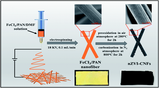
Firstly, FeCl3/PAN electrospun nanofibers with different FeCl3 contents (20 wt%, 40 wt%, and 60 wt%) to PAN polymer were prepared. The concentration of PAN solution is 10 wt% in DMF solvent. The parameters of electrospinning are listed as follows: 18 KV electrospinning voltage, 0.1 mL min−1 propeller speed, 35% humidity, and 20 cm between the needle to the collection; Secondly, the preparation of nZVI-CNFs nanocomposites were carried out according to the as-reported method.25,26 The as-prepared FeCl3/PAN electrospun nanofibers were placed in a vacuum tube furnace and preoxidized in air for 2 h at 280 °C with a heating rate of 2 °C min−1. Then, heating up to 800 °C with a heating rate of 10 °C min for 2 h. After cooling down to room temperature, the final sample was collected and named as nZVI-CNFs. During the preparation process, PAN nanofibers are transformed into flexible and highly conductive carbon nanofibers followed by pre-oxidation and carbonization. The FeCl3 was reduced by carbon to obtain nano zero valent iron nanoparticles at high temperature in the absence of oxygen. Meanwhile, the yellow nanofiber membrane precursor with iron ion color is transformed into black carbon nanofiber membrane after carbonization (Scheme 1). For comparison, pure carbon nanofibers derived from PAN nanofibers were prepared under the same conditions. Pure nZVI was synthesized according to the previously reported method.272.3. Cr(VI) removal experiments
In order to test the reduction capacity of nZVI-CNFs, 20 mg nZVI-CNFs was added into K2Cr2O7 solution with the Cr(VI) concentration of 10 mg L−1. The mixed solution was shaken in a rotary shaker at a speed of 180 rpm at 25 °C. The removal efficiency (RE) and removal capacity (RC) of Cr(VI) were calculated according to following equation:
 | (1) |
 | (2) |
Cr(VI) concentration in an aqueous solution is determined by direct UV-visible spectrophotometry of the diphenylcarbazide at a wavelength of 540 nm.28,29 The performance of nZVI-CNFs was further evaluated under various conditions. The effect of pH on the Cr(VI) removal was studied by adjusting the initial pH from 4 to 8. The Cr(VI) concentrations ranging from 5 to 100 mg L−1 were also tested and Langmuir and Freundlich isotherm models were used to analyze removal process. The equation is expressed as follows:30
 | (3) |
 | (4) |
In order to evaluate the stability of nZVI-CNFs, the produced nZVI-CNFs composites were placed at open environment for several days followed by Cr(VI) removal (pH = 7 and 10 mg L−1 Cr(VI)) assessment. All experiments mentioned above were carried out at 25 °C.
2.4. Characterization
The morphology of the nZVI-CNFs composite was characterized by scanning electron microscopy (SEM, Hitachi SU8020, Japan) images. Transmission electron microscope (TEM, Tecnai G2 F20 S-TWIN, USA) and energy dispersive X-ray spectroscopy (EDS, Horiba Emax 7593-H, Japan) mapping were operated to further investigate the details of the microstructure of the composite. The crystal structure before and after Cr(VI) removal were characterized by X-ray diffraction (XRD, D8 Advance, Germany) patterns. The surface element composition and chemical state were determined using X-ray photoelectron spectroscopy (XPS, Thermo Escalab 250Xi, USA) spectra.3. Results and discussions
3.1. Characterization of nZVI-CNFs
Morphologies of nZVI-CNFs nanocomposites are presented in Fig. 1. The nZVI-CNFs has still well nanofiber structure as shown in Fig. 1A. Meanwhile, nZVI-CNFs with an average diameter of 718 nm and rough surface are shown in Fig. 1B and C. From Fig. 1D, it can be seen that the surface of carbon nanofiber is uniformly loaded with spherical nanoparticles. The XRD pattern of nZVI-CNFs was shown in Fig. 1E. Apparent peaks at a 2θ angle of 44.6°, 65.0°, and 82.3° indicated the presence of nZVI (Fe0), which confirmed that the nZVI nanoparticles were load on the carbon nanofibers.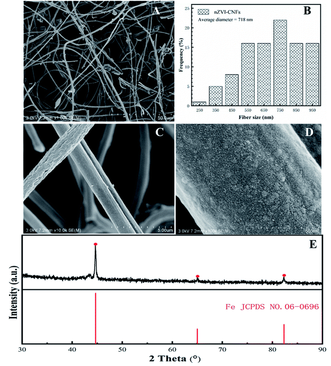 | ||
| Fig. 1 The different magnification SEM images (A, C and D); the diameter distribution (B); and the XRD pattern (E) of nZVI-CNFs before Cr(VI) removal. | ||
Fig. 2 shows the TEM images and element mapping of nZVI-CNFs. The nZVI-CNFs nanofiber structure is consistent with the SEM result (Fig. 2A), and black spherical spots were also visible in Fig. 2B. These globular nodules were proved to be nZVI nanoparticles by the TEM images (Fig. 2C), which were evenly loaded on surface of the electrospun carbon nanofibers (Fig. 2B and C). In the center of the nanoparticles, the lattice fringe of nZVI nanoparticles can be seen clearly. TEM image and analysis software (DigitalMicrograph) were used to estimate the surface spacing, which were 0.197 and 0.121 nm corresponding to surface of Fe0 (110) and surface of C (110), respectively. As shown in Fig. 2D, the nZVI nanoparticles were coated with graphitized carbon layer, which might help to accelerate electron transfer and improve their stability.31 The existence of Fe, C, N and O elements can be observed by the TEM element mapping images (Fig. 2F), which further confirm the successful synthesis of nZVI-CNFs (Table. S1†). Aggregation of nZVI particles was still observed, but much decreased relative to the unsupported nZVI nanoparticles. Thus, the results further prove that the confined cladding of electrospun nanofibers is beneficial to improve the dispersion of nZVI nanoparticles, which would be beneficial to improve the Cr(VI) removal. At the same time, heteroatomic doping is also beneficial to the adsorption and the reduction of Cr(VI) hexavalent chromium.32
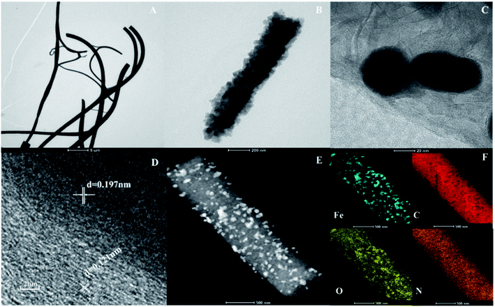 | ||
| Fig. 2 The TEM images (A and B); HR-TEM images (C and D); Element mapping of C, O, N and Fe (F) from (E) of nZVI-CNFs before Cr(VI) removal. | ||
3.2. Batch experiment of Cr(VI) removal
Fig. 3 shows the Cr(VI) removal efficiency by nZVI-CNFs with different nZVI contents. The pure carbon nanofiber derived from PAN nanofiber had a relatively low removal efficiency of about 10%. For different nZVI-CNFs composites, the removal rate was significantly improved with the increase of nZVI content. The removal efficiency of 20%-nZVI-CNFs increased by 6 folds comparing with the CNFs. For 40%-nZVI-CNFs and 60%-nZVI-CNFs, the removal efficiency further increased to 84.7% and 91.5%, respectively. Further increase in the concentration of iron (>60%) resulted in serious gelation of the electrospun solution, which was unable to electrospin due to the high viscosity. Therefore, in this experiment the maximum addition was set at 60%. Compared with the removal rate of pure nZVI system with the same content to the 60%-nZVI-CNFs, the composite indicated a much higher removal efficiency (91.5% vs. 39.7%). This also proves that zero-valent iron doped electrospun carbon nanofibers indeed improved the performance.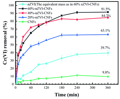 | ||
| Fig. 3 The comparison of Cr(VI) removal efficiency by nZVI-CNFs with different nZVI contents and pure nZVI. | ||
3.3. Isothermal models of Cr(VI) removal by nZVI-CNFs
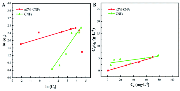
Fig. 4 shows that two typical isothermal models, Langmuir and Freundlich isothermal models, were selected to describe the experimental results of Cr(VI) removal process. In Freundlich isothermal model, the calculated Freundlich constants of nZVI-CNFs (KF = 8.2[(mg g−1)(L mg−1)1/n]) was much higher than that of CNFs (KF = 1.6[(mg g−1)(L mg−1)1/n]). The adsorption isotherm of nZVI-CNFs and CNFs fitted well to the Freundlich model with correlation coefficients (R2) of 0.997 and 0.929, respectively. Therefore, nZVI-CNFs have larger adsorption capacity than CNFs.33 In addition, the adsorption isotherm of nZVI-CNFs also fitted well to the Langmuir model with R2 = 0.992. Langmuir model suggested that the adsorption of Cr(VI) occurs on a homogeneous surface by monolayer adsorption, and no interaction happens between adsorbed species.13 Maximum adsorption capacity (qmax) determined by Langmuir model was 13.2 mg g−1.3.4. Stability of nZVI-CNFs
Fig. 5A shows the removal efficiency of Cr(VI) at different pH values ranging from 4 to 8. Higher removal efficiency was obtained at more acidic condition for both nZVI-CNFs and nZVI. It is well known that the reduction of Cr(VI) from iron-based materials is a process by surface conditioning and acid driving.34,35 The acid state can effectively reduce the surface passivation of iron and lead to the rapid corrosion of iron.36,37 When the Cr(VI) solution was changed from acid to alkaline, significant reduction in the removal efficiency was observed for nZVI. However, the removal efficiency only decreased by less than 20% (100% vs. 80.9%) for nZVI-CNFs, which may be due to the stable structure of the carbon coating (Fig. 5A). The relatively stable Cr(VI) removal efficiency at a wide range of pH (acid to weak alkaline) enables the current synthesized nZVI-CNFs composite to be used in more complex environments.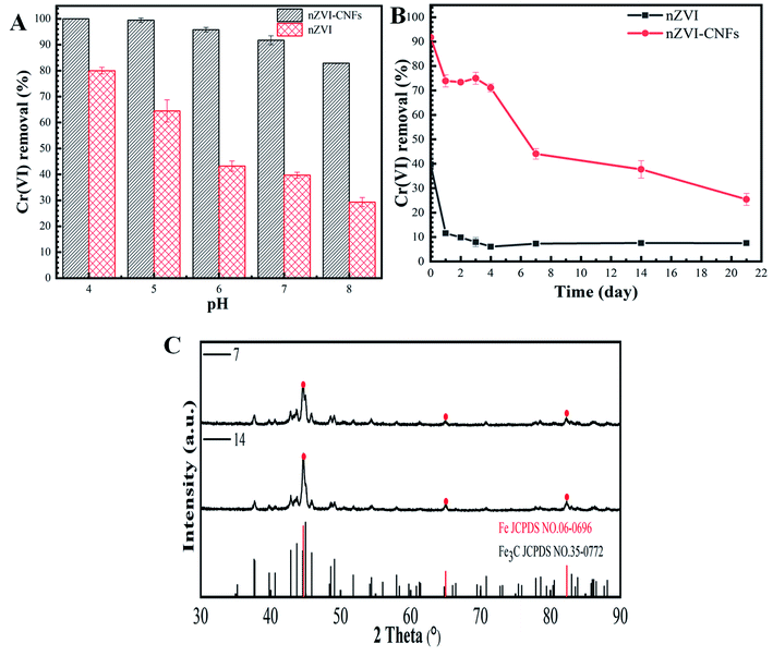 | ||
| Fig. 5 The Cr(VI) removal efficiency at different pH values ranging from 4 to 8 (A); the stability of the nZVI-CNFs composite at open environment (B); XRD patterns of nZVI-CNFs at 7 and 14 days (C). | ||
Fig. 5B shows the stability of the nZVI-CNFs composite at open environment. The carbon nanofiber coated nZVI structure of the nZVI-CNFs composite significantly enhanced the stability of nZVI comparing to the pure nZVI. It took only 4 days for the pure nZVI to significantly lose the Cr(VI) removal capacity (Only 15.0% removal capacity of the first day), while it took more than 20 days for the nZVI-CNFs to reach the higher level (Only 27.6% removal capacity of the first day). The XRD spectrums of the nZVI-CNFs at day 7 and 14 show similar pattern, suggesting a relatively stable structure of the composite. Although a small amount of iron carbide is formed, both samples contained significant amount of nZVI (Fig. 5C). Such improved stability might be due to the coating effect of carbon layer on nZVI, which is consistent with the existing theory that carbon coating can effectively increase the fastness of metal nanoparticles to carbon matrix and slow down acid corrosion and oxidation.38–40
3.5. Continuous experiment of Cr(VI) removal
The continuous experiment was conducted in the flow-through reactor (10 cm3) packed with 190 mg nZVI-CNFs. 360 mL of Cr(VI) solution (5.0 mg L−1) was pumped through the reactor at a speed of 1 mL min−1, resulting in a hydraulic retention time of 10 min. The treated Cr(VI) solution was sampled and measured for the remaining Cr(VI) concentration. After this, the same solution was pumped through the reactor again to get repeated treatment (Fig. 6A). Fig. 6B shows the Cr(VI) removal per each cycle of treatment decreases gradually with the increase of treatments as the nZVI-CNFs continuously reacted with the Cr(VI) ions and the active sites of nZVI-CNFs decreased accordingly. According to calculation, 2.1 mg L−1 is the total concentration removed after 9 cycles.41 It is worthwhile mentioning that no Fe element was detected in the effluent suggesting that the end products of Cr(VI) reduction were well-contained in the carbon nanofibers (CNFs) 3D structure even under flow through conditions. In order to demonstrate the presence of the produced end product in the system, the microstructure of the nZVI-CNFs composite after the reaction was analyzed and presented in the following sections.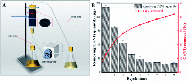 | ||
| Fig. 6 The schematic diagram of simulated reactor again to get repeated treatment (A); the Cr(VI) removal per each cycle of treatment (B). | ||
3.6. Mechanisms of Cr(VI) removal by nZVI-CNFs
The XRD patterns of nZVI-CNFs before and after the reaction with Cr(VI) are shown in Fig. 7A. The raw nZVI-CNFs composite displays clear nZVI crystals diffraction peaks before the reaction,26 which were disappeared after the Cr(VI) removal experiment. In meantime, diffraction peaks of FeO(OH) and CrO(OH) appeared simultaneously, which result accords with the common reaction mechanism of nZVI removing Cr(VI).37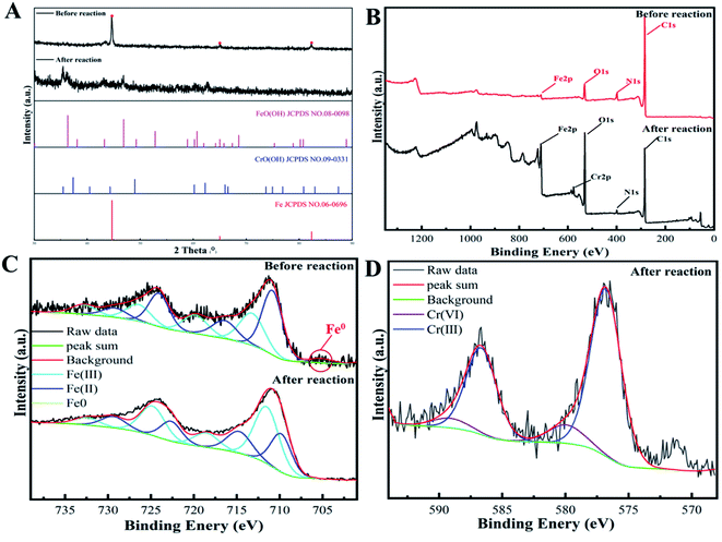 | ||
| Fig. 7 XRD patterns (A); XPS survey (B) and Fe2p XPS spectra (C) of nZVI-CNFs before and after Cr(VI) removal; Cr2p XPS spectra of nZVI-CNFs after Cr(VI) removal (D). | ||
To further verify the XRD results, the elemental composition and doping state of the nZVI-CNFs before and after the Cr(VI) removal were characterized by XPS spectra shown in Fig. 7B. Before the Cr(VI) removal, the nZVI-CNFs was composed of Fe, C, N, and O elements. The N and O doping are conducive to the surface adsorption reduction of Cr(VI) ions. After the Cr(VI) removal, the Cr element appeared, implying that Cr(VI) removal by nZVI-CNFs involved a chemisorption process with the reduction of Cr(VI) to Cr(III). Meanwhile, the content of O element increased significantly, which was due to the formation of hydroxide complexes. Fig. 7C showed the high resolution Fe2p XPS spectra before and after Cr(VI) removal. The peaks at 710.5 and 723.4 eV were assigned to Fe(II), while the peaks situated at 711.9 and 725.2 eV were ascribed to Fe(III), while the satellite peak positions for Fe(II) were 715.6 and 728.3 eV and those for Fe(III) were 719.5 and 732.3 eV.42 And the peaks at 705.3 was assigned to Fe0.28 Fitting these peaks gave the distribution of iron oxidation states. The calculated ratios of Fe(III)/Fe(II) before and after Cr(VI) removal were 14.2 and 16.9, respectively, indicating that Fe(II) content decreased. Usually, the Fe(II) content should be oxidized due to participation in the reaction, however, the decrease in the proportion of Fe(II) indicated that the introduction of CNFs may promote the reduction of Fe(III) to Fe(II) by obtaining electrons from nZVI (Fe0 − 2e → Fe2+, 2Fe3+ + Fe0 → 3Fe2+), and realize circulation. Moreover, some studies have shown that the adsorbed Fe(II) has higher activity, and can also change the transition of the iron surface oxide phase to mitigate passivation,43 both of which are beneficial to Cr(VI) removal. As exhibited in Fig. 7D, the photoelectron peaks for Cr2p3/2 and Cr2p1/2 generally occurred at 576.8 and 586.66 eV respectively, which indicated the formation of Cr(III) and the compound of Cr(III) formed at the surface of nZVI-CNFs.44 Since zero-valent iron is easily oxidized, the elemental changes and states of the nZVI-CNFs in pure water solution were further investigated (Fig. S1†). The results showed that the zero-valent iron phase was still existed and there is no signal of Cr element after reaction with pure water. Furthermore, the contents of various elements in different reaction conditions were compared in Table S2.† In the presence of Cr(VI) ions, the surface O element content was the highest, and a large amount of Cr element appeared. The results also proved that the oxidation of zero-valent iron mainly comes from the reduction of Cr(VI).
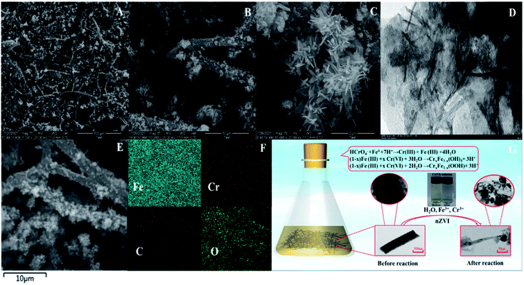
The structure and morphology of the product were characterized by SEM and TEM after reaction. As shown in Fig. 8A, the nZVI-CNFs composites kept typical CNFs structure and the framework of nZVI-CNFs maintained intact. The nZVI-CNFs composites after reaction exhibited large aggregates on surface of the nanofibers (Fig. 8B). The locally magnified SEM and TEM images of the aggregates showed a flower structure assembled by needlelike flake (Fig. 8C and D). This is consistent with the results reported in the literature.12,27 The reduction of the specific surface area from 386.135 to 189.299 m2 g−1 may have been due to structural change, but the discovery of hysteresis loops demonstrated mesoporous formation, possibly due to by-product formation (Fig. S2†).
The elemental mapping shows the existence of Fe, Cr, O elements, and the C element skeleton is clearly visible along the nanofiber (Fig. 8F). Based on the above results, a general mechanism of removing Cr(VI) from nZVI-CNFs was proposed and summarized, as shown in Fig. 8G. Fe0 in nZVI-CNFs plays an important role in Cr(VI) removal. In the main part, Fe0 directly reduced Cr(VI), and the reaction formed Fe(III) and Cr(III), and the reaction products were finally attached to nZVI-CNFS in the form of sediments. This conclusion was obtained by XRD comparison before and after the reaction. The other part of Fe0 was oxidized to Fe(II), and Cr(VI) was reduced by Fe(II). This is consistent with XRD and XPS results after the reaction. After this process, the solution of hexavalent chromium ion changed from light yellow before reaction to transparent colorless. Finally, the performance of this work is compared to other similar works, listed in Table 1.
| Number | Adsorbents | pH | Capacity (mg g−1) | References |
|---|---|---|---|---|
| 1 | Magnetic biochar | 2 | 11.56 | J. Cleaner Prod., 2020, 257, 120562 |
| 2 | mZVI/AC | 3.93 | 6.67 | Chem. Eng. J., 2020, 389, 122633 |
| 3 | nZVI-graphene | 3 | 24.60 | Chem. Eng. J., 2016, 288, 789 |
| 4 | nZVI/HCl-BC | — | 17.80 | J. Hazard. Mater., 2017, 332, 79 |
| 5 | NZVISDBC | 4 | 28.89 | Environ. Pollut., 2020, 265, 115018 |
| 6 | BS-nZVI | 7 | 8.00 | Environ. Sci. Pollut. Res., 2016, 23, 2613 |
| 7 | ECH-CS-NZVI | 6.7 | 6.67 | Chem. Eng. J., 2012, 189, 196 |
| 8 | FeS/carbon fibers | 2 | 81.62 | Front. Environ. Sci. Eng., 2020, 14, 1 |
| 9 | PAN/Fe(NO3)3 | 1 | 445.3 | Carbon, 2020, 166, 227 |
| 10 | Fe2O3/CNF | 5.5 | 75 | Chem. Eng. J., 2022, 429, 132108 |
| 11 | Fe-PhB-A-CNF | 4.5 | 41 | J. Water Process Eng., 2014, 3, 34 |
| 12 | nZVI-PCNFs | 7 | 13.2 | This work |
4. Conclusions
In this work, a novel nZVI-CNF composite was prepared and applied for the Cr(VI) removal from aqueous solution. Their morphologies and structures were characterized by SEM and TEM at various stages. Before Cr(VI) removal, the nZVI was embedded in the CNFs matrix relatively uniformly. After reaction, hydroxide complexes with a flower structure assembled by needlelike flake were attached to the nanofiber surface achieving a good retention effect. From batch experiment results, the Cr(VI) removal efficiency was much higher than that of a single component. Furthermore, the continuous removal experiment proved that it had an important continuous removal ability and practical application value. The effects of different PH values and placement time were studied, which showed good stability and strong adaptability to pH and placement time. The high crystal stability of the nZVI-CNFs was verified by XRD pattern. Kinetic studies showed that isotherm data was well described by Freundlich and Langmuir model. The maximum adsorption capacity determined by the Langmuir model was 13.2 mg g−1. Finally, the general reaction mechanism was revealed, which consists of two parts: Cr(VI) was reduced by Fe0 directly and Fe(II) indirectly from the oxidation of Fe0.Conflicts of interest
There are no conflicts to declare.Acknowledgements
This research was supported by the program of the Innovation/Entrepreneurship Program of Jiangsu Province, the China Postdoctoral Science Foundation (Grant no. 2020M671359), Distinguished Professor Foundation of Jiangsu Province, Natural Science Foundation of Jiangsu Province (Grant no. BK20200914), National Natural Science Foundation of China (Grant no. 62101216) and Priority Academic Program Development of Jiangsu Higher Education Institutions (PAPD-2018-87).References
- H. B. Wang, J. Y. Cai, Z. W. Liao, A. Jawad, J. Ifthikar, Z. L. Chen and Z. Q. Chen, Bioresour. Technol., 2020, 311, 123553 CrossRef CAS PubMed.
- L. H. Liu, X. Liu, D. Q. Wang, H. Lin and L. Huang, J. Cleaner Prod., 2020, 257, 120562 CrossRef CAS.
- W. H. Wang, B. B. Hu, C. Wang, Z. J. Liang, F. Y. Cui, Z. W. Zhao and C. Yang, Chem. Eng. J., 2020, 389, 122633 CrossRef CAS.
- K. V. G. Ravikumar1, D. Kumar1, A. Rajeshwari1, G. M. Madhu, P. Mrudula1, N. Chandrasekaran1 and A. Mukherjee1, Environ. Sci. Pollut. Res., 2015, 23, 2613–2627 CrossRef PubMed.
- Y. Fang, J. Wen, H. B. Zhang, Q. Wang and X. H. Hu, Environ. Pollut., 2020, 260, 114021 CrossRef CAS PubMed.
- W. Zou, C. H. Li, J. Hu and X. D. Hou, Talanta, 2020, 218, 121128 CrossRef CAS PubMed.
- Y. Wang, L. Yu, R. T. Wang, Y. Wang and X. D. Zhang, Sci. Total Environ., 2020, 726, 138625 CrossRef CAS PubMed.
- D. Mamais, C. Noutsopoulos, I. Kavallari, E. Nyktari, A. Kaldis, E. Panousi, G. Nikitopoulos, K. Antoniou and M. Nasioka, Chemosphere, 2016, 152, 238–244 CrossRef CAS PubMed.
- N. Habibul, Y. Hu, Y. K. Wang, W. Chen, H. Q. Yu and G. P. Sheng, Environ. Sci. Technol., 2016, 50, 3882–3889 CrossRef CAS PubMed.
- J. Zhao, X. Yang, G. W. Liang, Z. W. Wang, S. Li, Z. R. Wang and X. Y. Xie, Sci. Total Environ., 2020, 710, 136289 CrossRef CAS PubMed.
- J. Fan, X. Chen, Z. B. Xu, X. Y. Xu, L. Zhao, H. Qiu and X. D. Cao, J. Hazard. Mater., 2020, 398, 122901 CrossRef CAS PubMed.
- R. B. Fu, Y. P. Yang, Z. Xu, X. Zhang, X. P. Guo and D. S. Bi, Chemosphere, 2015, 138, 726–734 CrossRef CAS PubMed.
- P. Kumarathilaka, V. Jayaweera, H. Wijesekara, I. R. M. Kottegoda, S. R. D. Rosa and M. Vithanage1, J. Nanomater., 2016, 2016, 2813289 Search PubMed.
- Y. X. Song, S. Chen, N. You, H. T. Fan and L. N. Sun, Chemosphere, 2020, 255, 126917 CrossRef CAS PubMed.
- J. W. Ren, Y. ChulWoo, M. W. Yao, S. Lim, L. D. Tijing and H. K. Shon, Sci. Total Environ., 2019, 688, 787–796 CrossRef CAS PubMed.
- X. S. Lv, J. Xu, G. M. Jiang and X. H. Xu, Chemosphere, 2011, 85, 1204–1209 CrossRef CAS PubMed.
- Q. Zhang, Y. Y. Wang, Z. Wang, Z. J. Zhang, X. D. Wang and Z. L. Yang, J. Alloys Compd., 2021, 852, 156993 CrossRef CAS.
- D. Chauhan, J. Dwivedi and N. Sankararamakrishnan, Environ. Sci. Pollut. Res., 2014, 21, 9430–9442 CrossRef CAS PubMed.
- S. L. Xiao, M. W. Shen, R. Guo, S. Y. Wang and X. Y. Shi, J. Phys. Chem. C, 2009, 113, 18062–18068 CrossRef CAS.
- Y. P. Chen, L. M. Yang, J. P. Chen and Y. M. Zheng, J. Hazard. Mater., 2019, 371, 576–585 CrossRef CAS PubMed.
- H. Ma, Y. P. Huang, M. W. Shen, R. Guo, X. Y. Cao and X. Y. Shi, J. Hazard. Mater., 2012, 211–212, 349–356 CrossRef CAS PubMed.
- W. Qi, X. H. Yan, L. Duan, Y. Cui, Y. Yang and J. B. Li, Biomacromolecules, 2009, 10, 1212–1216 CrossRef CAS PubMed.
- S. Kidambi, J. H. Dai, J. Li and M. L. Bruening, J. Am. Chem. Soc., 2004, 126, 2658–2659 CrossRef CAS PubMed.
- K. C. Krogman, N. S. Zacharia, D. M. Grillo and P. T. Hammond, Chem. Mater., 2008, 20, 1924–1930 CrossRef CAS.
- E. V. Velez, L. L. Zarate and H. M. Valencia, J. Appl. Polym. Sci., 2019, 137, 48663 CrossRef.
- Y. Song, L. C. Wang, B. L. Lv, G. Z. Chang, W. Z. Jiao and Y. Z. Liu, Environ. Sci. Pollut. Res. Int., 2020, 27, 7015–7024 CrossRef CAS PubMed.
- H. R. Dong, J. M. Deng, Y. K. Xie, C. Zhang, Z. Jiang, Y. J. Cheng, K. J. Hou and G. M. Zeng, J. Hazard. Mater., 2017, 332, 79–86 CrossRef CAS PubMed.
- Z. H. Li, S. Y. Xu, G. H. Xiao, L. M. Qian and Y. Song, J. Environ. Manage., 2019, 244, 33–39 CrossRef CAS PubMed.
- M. Y. Zhang, K. X. Yi, X. W. Zhang, P. Han, W. Liu and M. P. Tong, J. Hazard. Mater., 2020, 388, 121822 CrossRef CAS PubMed.
- L. Fan, H. Y. Ren, X. Z. Ma, S. F. Zhou, J. Huang, W. Z. Jiao, G. S. Qi and Y. Z. Liu, Chem. Eng. J., 2020, 390, 124639 CrossRef.
- K. W. Jung, J. H. Kim and J. W. Choi, Composites, Part B, 2020, 187, 1078672 Search PubMed.
- Q. H. Su, Z. Su, W. Y. Xie, C. Tian, X. T. Su and Z. Lin, Environ. Pollut., 2020, 263, 114374 CrossRef CAS PubMed.
- N. A. Miranda, S. E. Baltazar, A. García, D. M. Lira, P. Sepúlveda, M. A. Rubio and D. Altbir, J. Hazard. Mater., 2016, 301, 371–380 CrossRef PubMed.
- F. L. Fu, J. Ma, L. P. Xie, B. Tang, W. J. Han and S. Y. Lin, J. Environ. Manage., 2013, 128, 822–827 CrossRef CAS PubMed.
- G. Gao, L. J. Nie, S. J. Yang, P. K. Jin, R. Z. Chen, D. H. Ding, X. C. Wang, W. D. Wang, K. Wu and Q. H. Zhang, Appl. Surf. Sci., 2018, 457, 1208–1217 CrossRef CAS.
- G. Z. Qu, L. Q. Kou, T. C. Wang, D. L. Liang and S. B. Hu, J. Environ. Manage., 2017, 201, 378–387 CrossRef CAS PubMed.
- Y. Qiu, Q. Zhang, B. Gao, M. Li, Z. X. Fan, W. J. Sang, H. R. Hao and X. N. Wei, Environ. Pollut., 2020, 265, 115018 CrossRef CAS PubMed.
- G. L. Sun, X. J. Li, Q. Q. Wang and H. H. Yan, Mater. Res. Bull., 2010, 45, 519–522 CrossRef CAS.
- X. L. Shu, J. Feng, J. D. Liao, D. D. Zhang, R. Q. Peng, Q. S. Shi and X. B. Xie, J. Alloys Compd., 2020, 848, 156556 CrossRef CAS.
- X. Sun, J. M. Fang, R. B. Xu, M. Y. Wang, H. T. Yang, Z. X. Han and J. H. Xu, J. Mol. Liq., 2020, 315, 113598 CrossRef CAS.
- P. Patil, M. Kigga, M. P. Bhat, M. G. Gatti, S. Kabiri, T. Altalhi, H. Y. Jung, D. Losic and M. Kurkuri, Chem. Eng. J., 2017, 327, 725 CrossRef CAS.
- H. W. Zou, E. D. Hua, S. Y. Yang, L. Gong and F. He, Sci. Total Environ., 2019, 650, 419–426 CrossRef CAS PubMed.
- L. L. He, D. S. Huang, Z. X. He, X. J. Yang, G. Z. Yue, J. Zhu, D. Astrucb and P. X. Zhao, J. Hazard. Mater., 2020, 388, 121761 CrossRef CAS PubMed.
- J. Li, M. J. Fan, M. Li and X. Liu, Sci. Total Environ., 2020, 717, 137112 CrossRef CAS PubMed.
Footnotes |
| † Electronic supplementary information (ESI) available. See DOI: 10.1039/d2ra00193d |
| ‡ The two authors who contributed equally to the work should be considered co-first authors. |
| This journal is © The Royal Society of Chemistry 2022 |

