 Open Access Article
Cyanide-free electrolyte for Au/Co–Au nano-multilayer electrodeposition utilising 5,5-dimethylhydantoin as a complexing agent†
Gong Luo ab,
Yuan Yuan*ab,
Deyu Lib,
Ning Li
 *b and
Guohui Yuanb
aCollege of Mechanical and Electrical Engineering, Guangdong University of Petrochemical Technology, Maoming, 525000, People's Republic of China. E-mail: YYuan865@hit.edu.cn; lininghit@263.net
bSchool of Chemistry and Chemical Engineering, Harbin Institute of Technology, Harbin 150001, People's Republic of China
First published on 11th March 2022
Abstract
A novel cyanide-free electrolyte was used in electrodepositing Au/Co–Au nano-multilayers. Firstly, an optimised electrolyte for Au–Co alloy electrodeposition was obtained from orthogonal experiments. The effect of current density and potential values on the deposited composition was investigated. Results showed that low current density and over-potential value promoted Au deposition. A large current density and high over-potential value resulted in high cobalt concentration. The co-deposition of gold and cobalt in this study system was canonical. When the electrode potential was positive (−0.6 V, −0.7 V vs. saturated calomel electrode (SCE)), only gold was deposited; when the potential was negative (−0.8 V vs. SCE), gold and cobalt were co-deposited. Using an optimised cyanide-free electrolyte produced Au/94.07 at% Co–Au multi-layers with a gold layer of approximately 20 nm and a 94.07 at% Co–Au alloy layer of approximately 90 nm in the 5,5-dimethylhydantoin-containing, cyanide-free system.
Introduction
Au–Co alloy (so called hard gold) electroplating is widely used in printed circuit board (PCB) manufacturing, due to its good contact resistance performance, high hardness and chemical stability. The traditional application of Au–Co alloy is based on the physical and chemical properties of gold. Cobalt is used as a strengthening phase.1,2 The performance of gold cobalt alloy coating is adjustable with the increase in cobalt content, which breaks the traditional idea of uniform coating based on gold.3–5 It makes the structure and function of the coating develop to diversification.6–9 Development of new structure and functional coatings has become a new focus of Au–Co alloy research.10,11 German physicist Peter Grünberg and French physicist Albert Fert observed giant magnetoresistance,12 in iron/chromium/iron and iron/chromium multi-layer films in 1988. E. Vélu et al. measured a GMR of 3% at 4.2 K for Co/Au sandwiches, fabricated by ultrahigh vacuum evaporation.10 An Au/Co granular structure with GMR of 2.4% at 10 K, fabricated by a melt-spinning technique was reported.18 Valizadeh et al.13–16 fabricated Au/Co multi-layer films by electrodeposition in cyanide-containing electrolyte. In electrodeposition, cobalt-rich deposits were deposited at −1.1 mV (vs. Ag/AgCl) potential, whereas gold-rich deposits were deposited at −0.049 mV (vs. Ag/AgCl) potential. Au-0.1 wt% Co alloy and Au-97 wt% Co alloy multi-layers were obtained. Then, a 12 nm cobalt-rich layer and a 4 nm pure gold layer were electrodeposited on the polycarbonate film with the designed bath to obtain Au/Co multi-layer nanowires.Au–Co alloys and Au/Co multi-layers have been fabricated from sulphur-containing cyanide-free electrolyte17,18 Results showed that a low citric acid concentration (0.47 M) at pH 6.15 is favourable for multi-layered Au/Co deposits with disparate compositions in each layer. An increase in citric acid concentration or pH requires a large applied current density to achieve the same cobalt concentration, resulting in a decrease in current efficiency. When the current density is 1 mA cm−2, the gold content of the coating reaches 99.5 wt%. When the current density exceeds 100 mA cm−2, cobalt-rich coatings with cobalt contents higher than 98.7 wt% can be obtained. In the study, with the change in coating thickness, the change in magnetic field on the resistance of the multi-layer structure is different to some extent, and the resistance reduction measured on the 3 nm gold and 5 nm cobalt-rich overlapping coating prepared in this study reaches 13%.
At present, studies on the preparation of Au/Co multi-layers coatings mainly focus on cyanide and sulphite systems.19–21 However, sulphur-containing electrolytes are unsatisfactory because of the following reactions:22
| 3Au+ → 2Au(s) + Au3+ | (1) |
| SO32− + H2O → SO2 (g) + 2OH− | (2) |
Sulphite-containing electrolytes contain particles at the interface, which lead to the black plate phenomenon. Hydantoin as a new metal iron complexing, with good solubility and stability in aqueous solutions has received a number of attentions in gold electrodepositing. Among a series of hydantoin derivatives, 5,5-dimethylhydantoin (DMH) was selected as a complexing agent for the cyanide-free gold electroplating electrolyte. H NMR spectra of the gold electroplating electrolytes were employed to reveal that strong coordination bonding of DMH to Au(III) was present, and that [Au(DMH)4] was the quantitative complexation structure.23–26 In this work, a novel cyanide-free electrolyte for Au/Co–Au nano-multilayer electrodeposition was reported. The structure of Au/Co multi-layer coatings was characterised, which provided an experimental basis for the application of the non-cyanide plating solution system in preparing Au–Co overlapped coatings in the signal bath. The novel electrolyte would have an extensive application in manufacturing Au/Co–Au nano-multilayer cyanide-free electroplating.
Experimental
Before the preparation and characterisation of Au/Co overlapping coating, orthogonal experiments were carried out on DMH system gold-plated cobalt alloy, as shown in ESI, PART 1.†27 The optimal combination of factors of the best plating solution and overall performance of the coating was obtained as follows: DMH 18 g L−1, NaAuCl4·2H2O 2 g L−1, CoSO4·7H2O 0.5 g L−1, C6H8O7·H2O (citric acid) 20 g L−1, pH 9. To improve coating quality, the total molar amount of gold/cobalt was unchanged, that is, Au + Co = 6.15 × 10⁻³ mol L−1. The Au/Co ratio was set to 4/1, 1/4, 1/9, 1/14 and 1/50 for plating solution preparation.Au–Co films were prepared by constant current method and constant potential. The electrodepositing current densities and constant potential used in Au/Co–Au nano-multilayer electrolytes ranged from 0.10 A dm−2 to 3.00 A dm−2 and −0.6 V to −1.3 V vs. saturated calomel electrode (SCE) 25 ± 2 °C, and the plating time was 100 s.
A step was taken to improve the ratio of gold and cobalt in the bath and achieve a wide range of composition-adjustable electrodeposition. The stability of pH 9 plating solution decreases with increasing cobalt ion concentration. With the electrode's stability taken into consideration, the plating solution mediated by Co-bath components of Au–Co alloy is generally acidic. The design and electrodeposition of the electroplating electrolyte with Au/Co of 1/50 were carried out at pH 4.6.
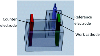
All electrochemical measurements were performed using a three-electrode electrochemical cell on a CHI760D electrochemical workstation. An SCE and a titanium electrode covered by iridium oxide (the electrode work area was 2 × 2 cm2) were used as reference and counter electrodes, respectively. A copper electrode with a work size of 2 × 2 cm2 was used as work cathode, where gold films are deposited. Polarisation curves from −0.2 V to −1.5 V were carried out with a sweep rate of 100 mV s−1. All electrochemical measurements were performed at room temperature, and all potentials presented in the article were versus SCE. The experimental condition and data are shown in Fig. 1.
Scanning electron microscopy (SEM) and a scanner were used to analyse the micromorphology and macromorphology of Au/Co multi-layer, respectively. The element contents of the gold layer were determined by energy dispersive spectrometry. X-Ray Diffraction (XRD) analysis was carried out on a D/max-3C X-ray diffractometer at a scanning rate of 0.02° s−1 with Cu Kα radiation. The elemental analysis of the electrodeposit was performed to analyze the purity of the deposit by X-ray photoelectron spectroscopy (XPS) on a PHI 5700 ESCA System, with an excitation source of Al Kα radiation (photoelectron energy of 1486.6 eV) and hemispherical precision electron energy analyzer.
Result and discussion
Galvanostatic deposition
The components of Au–Co alloy deposits obtained under different components and current densities are summarised in Table S3.† Table S3† shows that the Au–Co alloy deposits obtained by short-time electrodeposition under small current density basically did not contain cobalt. With the increase in electrodeposition current density, the cobalt content in the deposited gold cobalt alloy increased. At the same time, the decrease in Au/Co in the plating solution also increased the cobalt content in the deposited gold cobalt alloy. At low current density, the decrease in Au/Co ratio in the plating solution cannot significantly change the phenomenon of cobalt free in the deposit.This phenomenon shows that the polarisation of the electrode surface is limited when plating at a small current density, which is insufficient to make cobalt discharge deposition on the electric surface. When the current density was slightly higher, the polarisation of the electrode surface was sufficient to stimulate cobalt deposition. The decrease in Au/Co ratio in the plating solution can provide more cobalt ions on the electrode surface and increase cobalt content in the alloy deposits. At the same time, the current density was 1.0 A dm−2, and the cobalt content in deposit can reach 50 at% by adjusting Au/Co ratio in the electrolyte.
A single solution electrodeposition of 50 at% was significant. However, the modulation electrodeposition of cobalt content cannot meet the needs of the design and preparation of multi-layers. Therefore, on the basis of current density designed above, large current densities were used in the experiment, namely, 2.0 and 3.0 A dm−2.
With the increase in cobalt content in the electrolyte and the current density, the cobalt content in alloy deposits increased. Then, the cobalt content levels peaked at 74.80 at% in multiple experiments. For 74.80 at% cobalt content coating, the current density reached 3.0 A dm−2. At this time, hydrogen evolution appeared in the plating solution during intense plating. In addition, obvious scorched coating was found on the surface.
Thus, improving the cobalt content in the coating further by increasing the current density is no longer practical. High current is no longer used to promote cobalt deposition but to aggravate extra hydrogen evolution reaction.
Potentiostatic deposition
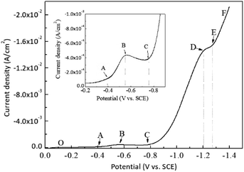
Potentiostatic deposition was adopted to control the cobalt content in the coating in a wide range. On the basis of the above experimental data of adjustable deposits by controlling current density, the deposited alloy components changed quickly, and the Co content was difficult to control.27,28 Before the electrodeposition experiment, the electrodeposition of the prepared electrolyte was analysed. The cathodic polarisation curve of electrodeposition is shown in Fig. 2.As shown in Fig. 2, no discharge deposition of gold and cobalt occurred in the OA section of the polarisation curve. When the potential scanning was negative to point A, the gold started to discharge and deposition, and the discharge rate of AB gradually accelerated with the potential shifting negative.
The BC section of cathodic polarisation curve decreased instead of increasing, indicating that the electrodeposition of gold changed from electrochemical control to mass transfer control. In the CD section, the deposition current increased again, indicating that cobalt started to discharge on the electrode surface. In the DE section, the rising trend of the current slowed down, indicating that the discharge deposition of cobalt gradually changed from electrochemical control to diffusion mass transfer control. In the EF section, the current increased again because a new electrochemical reaction occurred to provide a new current increase, corresponding to the occurrence of hydrogen evolution reaction.
On the basis of the above analysis, the co-deposition of gold and cobalt in this study system was canonical. That is, only gold deposition occurred at a relatively positive electrode potential, and cobalt discharge deposition occurred when the electrode potential moved negatively enough to stimulate cobalt deposition. This type of deposition is similar to the type of Au–Co deposition reported in cyanide and sulphite systems.15,17 On the basis of the analysis of cathodic polarisation curve, the Au/Co ratio in the coating can be controlled effectively by controlling the deposition potential, and the composition-adjustable electrodeposition can be realised finally.
On the basis of the discharge difference in Au/Co at different deposition potentials in the polarisation curve, the electrodeposition experiment of Au–Co alloy was carried out at −0.6, −0.7, −0.8, −0.85, −0.9, −0.95, −1.0, −1.1, −1.2, −1.3 V vs. SCE potentials. The component test results of each sample obtained after implementation are shown in Table S4.†
As shown in Table S4,† the cobalt content in the deposited alloy gradually increased with the negative shift of deposition potential, which is the same as the deposition rule of the existing Au/Co system. Pure gold and the highest cobalt content of 94.07 at% were obtained during electrodeposition in the same electrolyte. At this time, the gold content in the coating was very small and basically met the needs of preparing Au/Co multi-layers.
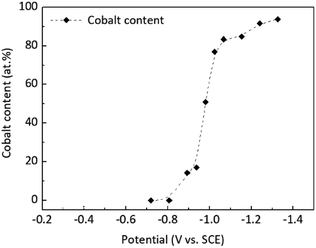
At low polarisation values of −0.6 and −0.7 V vs. SCE, the deposit contained only gold and no cobalt. This result indicates that the deposits contain small cobalt content when the electrodeposition current of gold corresponds to the deposition at low over-potential, which is the same as the previous conclusion of deposits obtained by controlling deposition with different current densities. Thus, controlled potential deposition and controlled current deposition have the same effect on alloy deposition. In addition, a deposition at −1.3 V vs. SCE was applied to obtain a coating with a cobalt content of approximately 94.07 at%. Compared with the cathode polarisation curve, the electrode potential shifted negative, and the electrode surface showed significant hydrogen evolution, which is unsuitable for experiments under a negative electrode potential. The relationship between electrodeposition potential and deposits' components is shown in Fig. 3.
As shown in Fig. 3, when the potential was −0.6 and −0.7 V vs. SCE, no cobalt was found in the deposits, which corresponded well with the cobalt deposition beginning at −0.8 V as reflected in the polarisation curve. When the deposition potential was more negative than −0.8 V, the cobalt content in deposits increased rapidly. When the deposition potential reached −1 V, the increase rate of cobalt content in the deposits decreased obviously. This result indicates that a positive electrode potential is conducive to obtaining low-cobalt and high-gold deposits, whereas a negative electrode potential is conducive to obtaining low-cobalt and high-cobalt deposits, which agrees with the results obtained by the aforementioned current-controlled deposition.
In this study, the electrodeposition of Au–Co alloy from pure gold to a cobalt content of 94.07 at% in a single system was realised by adjusting the metal ion ratio (Au3+/Co2+) in the electrolyte and the electrodeposition conditions in the plating solution as follows: DMH 18 g L−1, NaAuCl4·2H2O + CoSO4·7H2O = 6.15 × 10⁻³ mol L−1, Au3+/Co2+ = 1/50, C6H8O7·H2O (citric acid) 20 g L−1, pH 4.6. In addition, the potential-controlled deposition can be more intuitively regulated by the reaction that can occur at the deposition potential exerted by the reaction deposition with the polarisation curve. Therefore, achieving the composition-adjustable electrodeposition of Au–Co alloy in this study system by adjusting the deposition potential is favourable.
Au/Co nano-multilayer electrodeposition
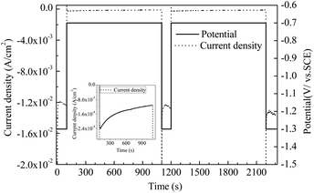
The above study shows that the adjustable electrodeposition of alloy components can be realised by controlling the metal ion ratio and electrodeposition potential in the plating solution. Basing from the experimental results and the analysis of the rule of electrodeposition of Au–Co alloy, this study designed the step potential deposition as shown in Fig. 4 to prepare Au/Co–Au nano-multilayers. The response current during electrodeposition is also described in the Fig. 4.The solid black line in Fig. 4 is the potential signal, pure gold deposited at −0.7 V vs. SCE, and high cobalt alloy deposited at −1.3 V vs. SCE. The dashed black line is the current transition curve obtained during electrodepositing. The current and potential curves show that a more negative electrode potential (−1.3 V vs. SCE) corresponds to a higher deposition current while a more positive deposition potential (−0.7 V vs. SCE) corresponds to a lower deposition current, which is consistent with the law reflected in Fig. 3. A short deposition time of 100 s was set under negative potential (−1.3 V vs. SCE) and a long deposition time of 1000 s was set under positive potential (−0.7 V vs. SCE) to narrow the difference of coating thickness between high and low potentials.
The potential-step electrodeposition method was used to obtain Au/Co-rich-Au multi-layers, which lays a foundation for the application of the cyanogen free electro-deposition system in magnetoresistance coating. The section structure of the above multi-layers prepared by step potential electrodeposition is shown in Fig. 5.
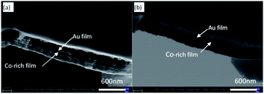 | ||
| Fig. 5 SEM images of cross-section of Au/Co-rich multi-layers; (a) second electron image; (b) back scattered electron image. | ||
An obvious layered structure is shown in Fig. 5a, but the thickness of the two coatings is different. Thus, the boundary and thickness of the coatings are difficult to distinguish. The images collected using the backscattered electron phase formation mode are shown in Fig. 5b. Backscattering electron imaging is sensitive to the relative atomic weight of elements, and two layers with different colour depths can be observed in the coating. The darker layer is gold layer, whereas the lighter and thicker layer is low gold and high cobalt layer.
The thickness of the overlapped coating structure was measured by SEM. The thickness of the overlapped coating prepared by experimental study was approximately 20 nm in the gold layer, and the thickness of the low gold and high cobalt coating was approximately 90 nm. In addition, the deposition velocity of the electrode with negative potential was much higher than that of the electrode with positive potential. A good matching relationship was observed between the deposition current with a higher negative electrode potential and the deposition current with a low positive electrode potential as shown in Fig. 3. The cross-sectional morphology confirmed that the multi-layer structure of Au/Co alloy coatings with different compositions was obtained. The EDS mapping also reflects multi-layer structure in gold mapping, as shown in Fig. S3.†
XRD patterns of Au–Co electrodeposits obtained in orthogonal experiments are shown in ESI, PART 2 and Fig. S4.† Diffraction peaks can be seen at 2θ = 38.2°, 43.3°, 44.4°, 74.1°, 89.9°. Take the non-equilibrium process of electrodepositing into consideration, the diffraction peaks correspond to Au(1 1 1), Cu(1 1 1), Au(2 0 0), Cu(2 2 0), Cu(3 1 1), (Au-JCPDS: 04-0784; Cu-JCPDS: 04-0836), respectively. However, the diffraction peaks of cobalt are invisible.
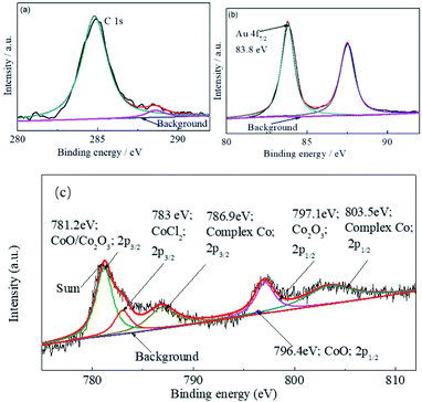
XPS analysis was employed to verify the products generated during the deposition as shown in Fig. 6. The binding energy of the Au 4f7/2 peak at 83.8 eV was used as an internal standard of the XPS survey scan for the electrodeposit, as the C 1s internal standard might be influenced by other contaminants absorbed on the film surface. As shown in Fig. 6, obvious signals for Au, C, CoOx, CoCl2 and complexed Co are observed on the original deposits' surface. Signals for CoOx was generated by the oxidation of deposited cobalt.29 It means that there was some complex cobalt and CoOx entrained into the electrodeposit.
The multi-layers of the Au/Co-rich layer were obtained by designing step potential in the experiment. This experiment provides a new system for the preparation of Au/Co multi-layers by cyanide-free electrodeposition containing DMH.
Conclusion
This study characterised the process of using a non-cyanide single bath to electrodeposit Au/Co multi-layers. During Au, Co deposition, the co-deposition of gold and cobalt in this study system was canonical. At low polarisation values of −0.6 and −0.7 V vs. SCE, the deposit contained only gold and no cobalt. The Co deposition reaction occurred at more negative potentials than −0.8 V vs. SCE. An Au/Co multi-layer of approximately 20 nm gold layer and approximately 90 nm Au-94.07 at% Co alloy coating was prepared in the new developed cyanide-free plating solution system. This work provides a new direction for the further use of Au–Co alloy plating in the cyanide-free system. In the follow-up study, we will further analyse the structure and properties of overlapping coatings.Conflicts of interest
There are no conflicts to declare.Acknowledgements
This study was performed with the support of the fund “Research Project of Guangdong University of Petrochemical Technology (2019rc069), Natural science project of Education Department of Guangdong Province (2021KTSCX079) and Science and technology project of Maoming City (2021019)”.References
- F. H. Reid, Gold Bull., 1973, 6, 77–81 CrossRef.
- M. Antler, Gold Bull., 1975, 8, 86–87 CrossRef.
- S. C. Abrahams, J. L. Bernstein, R. Liminga and E. T. Eisenmann, Chem. Phys., 1980, 73, 4585–4590 CAS.
- H. Okamoto, T. B. Massalski, T. Nishizawa and M. Hasebe, J. Phase Equilib., 1985, 6, 449–454 CAS.
- L. Qu, J. Zhao, J. Yang, Y. Sun and C. Liu, Opt. Mater. Express, 2021, 11, 1176 CrossRef.
- K. Inoue, N. Sasaki, T. Sasadaira, T. Watanabe and T. Nakata, Mater. Trans., 2006, 47, 1546–1549 CrossRef CAS.
- F. Xia, H. Song, Y. Zhao, W. M. Zhao and Z. X. Dai, Measurement, 2020, 164, 108083 CrossRef.
- M. Kamiko and J.-G. Ha, Solid State Commun., 2021, 327, 114213 CrossRef CAS.
- Y. Kikuchi and T. Tanaka, Jpn. J. Appl. Phys., 2018, 57, 110305 CrossRef.
- E. Vélu, C. Dupas, D. Renard, J. P. Renard and J. Seiden, Phys. Rev. B: Condens. Matter Mater. Phys., 1988, 37, 668–671 CrossRef PubMed.
- T. Takahata, S. Araki and T. Shinjo, J. Magn. Magn. Mater., 1989, 82, 287–293 CrossRef CAS.
- C. Rizal, B. Moa, J. Wingert and O. G. Shpyrko, IEEE Trans. Magn., 2015, 51, 1–6 CAS.
- S. Valizadeh, G. Holmbom and P. Leisner, Surf. Coat. Technol., 1998, 105, 213–217 CrossRef CAS.
- S. Valizadeh, J. M. George, P. Leisner and L. Hultman, Thin Solid Films, 2002, 402, 262–271 CrossRef CAS.
- S. Valizadeh, L. Hultman, J. M. George and P. Leisner, Adv. Funct. Mater., 2002, 12, 766–772 CrossRef CAS.
- S. Valizadeh, E. B. Svedberg and P. Leisner, J. Appl. Electrochem., 2002, 32, 97–104 CrossRef CAS.
- M. Guan and E. J. Podlaha, ECS Trans., 2007, 3, 347–356 CrossRef CAS.
- M. Guan and E. J. Podlaha, J. Appl. Electrochem., 2007, 37, 549–555 CrossRef CAS.
- Y. Ohtani, K. Sugawara, K. Nemoto, A. Si-Iiozawa, A. Yamaguchi, K. Oyaizu and M. Yuasa, J. Surf. Finish. Soc. Jpn., 2004, 55, 933–936 CrossRef CAS.
- Y. Ohtani, T. Saito, K. Sugawara, A. Shiozawa, A. Yamaguchi, K. Oyaizu and M. Yuasa, J. Surf. Finish. Soc. Jpn., 2005, 56, 479–480 CrossRef CAS.
- Y. Ohtani, K. Sugawara, K. Nemoto, A. Shiozawa, A. Yamaguchi, K. Oyaizu and M. Yuasa, J. Surf. Finish. Soc. Jpn., 2006, 57, 167–171 CrossRef CAS.
- S. Dimitrijević, M. Rajčić-Vujasinović and V. Trujić, Int. J. Electrochem. Sci., 2013, 8, 6620–6646 Search PubMed.
- J. Zhang, A. Liu, X. Ren, J. Zhang, P. Yang and M. An, RSC Adv., 2014, 4, 38012–38026 RSC.
- G. Luo, G. Yuan and N. Li, RSC Adv., 2016, 6, 61341–61345 RSC.
- G. Luo, D. Li, G. Yuan and N. Li, J. Electrochem. Soc., 2018, 165, D147–D151 CrossRef CAS.
- Y. Yuan, G. Luo and N. Li, RSC Adv., 2021, 11, 31526–31532 RSC.
- G. Luo, D. Li, G. Yuan and N. Li, J. Electrochem. Soc., 2018, 165, D107–D109 CrossRef CAS.
- Y. Tian, Y. An, S. Xiong, J. Feng and Y. Qian, J. Mater. Chem. A, 2019, 7, 9716–9725 RSC.
- L. Chalumeau, M. Wery, H. F. Ayedi, M. M. Chabouni and C. Leclere, Surf. Coat. Technol., 2006, 201, 1363–1372 CrossRef CAS.
Footnote |
| † Electronic supplementary information (ESI) available. See DOI: 10.1039/d2ra00104g |
| This journal is © The Royal Society of Chemistry 2022 |

