 Open Access Article
Polymer microgels for the stabilization of gold nanoparticles and their application in the catalytic reduction of nitroarenes in aqueous media†
Muhammad Arif ab,
Muhammad Shahid
 a,
Ahmad Irfancd,
Jan Nisar
 e,
Weitai Wuf,
Zahoor H. Farooqi
 *a and
Robina Begum
 *a
*a
aSchool of Chemistry, University of the Punjab, New Campus, Lahore 54590, Pakistan. E-mail: zhfarooqi@gmail.com; Zahoor.chem@pu.edu.pk; robina.hons@pu.edu.pk
bDepartment of Chemistry, School of Science, University of Management and Technology, Lahore 54770, Pakistan
cResearch Center for Advanced Materials Science (RCAMS), King Khalid University, P.O. Box 9004, Abha 61413, Saudi Arabia
dDepartment of Chemistry, Faculty of Science, King Khalid University, P.O. Box 9004, Abha 61413, Saudi Arabia
eNational Centre of Excellence in Physical Chemistry, University of Peshawar, Peshawar 25120, Pakistan
fState Key Laboratory for Physical Chemistry of Solid Surfaces, Collaborative Innovation Center of Chemistry for Energy Materials, The Key Laboratory for Chemical Biology of Fujian Province, Department of Chemistry, College of Chemistry and Chemical Engineering, Xiamen University, Xiamen, Fujian 361005, China
First published on 10th February 2022
Abstract
Polymer microgels containing a polystyrene core and poly(N-isopropylmethacrylamide) shell were synthesized in aqueous media following a free radical precipitation polymerization. Au nanoparticles were fabricated into the shell region of the core–shell microgels denoted as P(STY@NIPM) by the in situ reduction of chloroauric acid with sodium borohydride. Various characterization techniques such as transmission electron microscopy (TEM), ultraviolet–visible spectroscopy (UV-visible) and Fourier transform infrared spectroscopy (FTIR) were used for the characterization of Au–P(STY@NIPM). The catalytic potential of Au–P(STY@NIPM) toward the reductive reaction of 4-nitrophenol (4NP) under various reaction conditions was evaluated. The Arrhenius and Eyring parameters for the catalytic reduction of 4NP were determined to explore the process of catalysis. A variety of nitroarenes were converted successfully into their corresponding aminoarenes with good to excellent yields in the presence of the Au–P(STY@NIPM) system using NaBH4 as a reductant. The Au–P(STY@NIPM) system was found to be an efficient and recyclable catalyst with no significant loss in its catalytic efficiency.
1. Introduction
Water pollution has become a threat to the health of human beings as well as aquatic life.1 There are a lot of chemical species responsible for the pollution of water reservoirs such as heavy metals,2 dyes,3 and pesticides.4–6 Nitroarenes are also chemicals responsible for water pollution. The complete removal of nitroarenes from water is very difficult.7,8 However, they can be converted to less toxic and useful species in the aqueous medium. The reduction of nitroarenes to aryl amines using suitable catalysts has been adopted as a solution to the aforementioned problem. Aryl amines are used as intermediates for the synthesis of biochemicals,9 antioxidants,10 polymers,11 pharmaceuticals,12 dyes,13 and fine chemicals.14 Generally, aryl amines are synthesized by reducing nitro compounds using suitable catalysts. Both homogeneous15,16 and heterogeneous catalysis17 are used for this purpose. Generally, homogeneous catalysts are lethal, costly, and commercially unavailable, and their recycling is not easy, while heterogeneous catalysis has a poisoning problem. Nanocatalysis presents the best solution to the above-mentioned problems related to both homogeneous and heterogeneous catalysis.18 Therefore, in the last decade, reductive reactions of nitroarenes to aryl amines using metal nanoparticles have attracted significant attention.19 Monometallic20–22 and bimetallic23 nanoparticles of Pd, Pt, and Rh are commonly used catalytic systems for the reduction of nitroarenes in water; however, such catalysts cannot be used on an industrial scale because of the high cost of the precursor salts of these precious metals. Furthermore, the hydrogenation of nitroarenes is usually performed using such nanoparticles and extremely explosive molecular hydrogen as the reductant.24,25 Transfer hydrogenation is an alternate method for the reduction of nitroarenes. In this way, the use of molecular hydrogen can be avoided26 but it requires organic liquids or a mixture of liquids as the solvent system at elevated temperature and recovery of the catalyst is not possible. Therefore, the reductive catalytic reaction of nitroarenes using metal nanoparticles in the solution phase has become the best strategy for the conversion of nitroarenes to aryl amines. Both noble27 and non-noble28 metal nanoparticles may be used for this purpose. Although nanoparticles of some inexpensive metals have been reported for the reductive reactions of nitroarenes,29–31 but these nanoparticles are not stable and cannot be recovered for their re-use as catalysts. The catalytic reductive reaction of nitroarenes using NaBH4 reductant in the presence of efficient and highly stable Au nanoparticles supported on suitable systems in water presents a solution to all the above-mentioned problems.32 Surfactants,33 ionic liquids,34 dendrimers,35 block copolymers,36 and microgels37 are used as supporting systems to stabilize Au nanoparticles and to enhance their catalytic activity.The use of microgel particles as microreactors for the incorporation and stabilization of gold nanoparticles (Au NPs) has gained much interest.38–41 Au nanoparticles are encapsulated and stabilized within the cavities of microgel particles via donor–acceptor interactions between microgel functionalities and metal nanoparticles.38 We recently reviewed gold nanoparticles-loaded polymer microgel systems for various applications, including their use in catalysis.39 Usually Au nanoparticles are loaded in homogeneous microgel systems to form hybrid microgels for catalytic applications, but it is difficult to recover such kind of hybrid catalysts from the reaction mixture after catalysis via ordinary centrifugation for their re-use.42–44 Ultra-centrifugation (with a high very high rpm) is needed for this purpose. This problem may be overcome by designing core–shell microgels with a highly dense/solid polystyrene core and crosslinked polymer shell filled with Au nanoparticles. According to a literature survey, the manufacturing and characterization of Au–P(STY@NIPM) hybrid microgels for the catalytic reductive reaction of nitroarenes have not yet been reported as an easily recoverable catalyst.
Consequently in the present work, the manufacturing, characterization, and catalytic performance of Au nanoparticles stabilized in P(STY@NIPM) were investigated. A wide variety of amines was synthesized by the reductive catalytic reactions of their respective nitroarenes in aqueous medium under mild reaction conditions. The catalytic activity of Au–P(STY@NIPM) hybrid microgels under various reaction conditions was studied to evaluate various kinetic parameters. The catalytic reduction mechanism of nitroarenes is proposed on the basis of the results obtained.
2. Material and methods
2.1 Materials
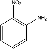
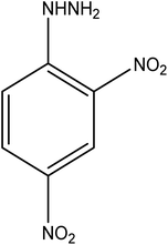
Styrene (STY), N-isopropylmethacrylamide (NIPM) (98%), N,N-methylenebisacrylamide (MBIS) (99%), ammonium per sulfate (APs) (99%), sodium dodecyl sulfate (SDS) (98%), sodium borohydride (NaBH4) (98%), 2-nitrophenol (2NP), 4-nitrophenol (4NP), 3-nitrophenol (3NP), 4-chloronitrobenzene (4NCB), 2-nitroaniline (2NA), 3-nitroaniline (3NA), 4-nitroaniline (4NA), 2-amino-4-nitroanisole (2A4NA), 4-nitrophenylhydrazine (4NPH), 2,4-dinitrophenylhydrazine (2,4DNPH), and tetrachloroauric(III) acid trihydrate (HAuCl4·3H2O) were obtained from Sigma Aldrich (Germany). No further purification of the chemicals was done except STY. STY was purified via vacuum filtration by passing it through alumina (Al2O3) to remove the inhibitor. Deionized water was used in all the experimental work. The membrane for dialysis (cut off = 12![[thin space (1/6-em)]](https://www.rsc.org/images/entities/char_2009.gif) 000–14
000–14![[thin space (1/6-em)]](https://www.rsc.org/images/entities/char_2009.gif) 000) was obtained from Scharlu and was used for the removal of unreacted reactants from the microgel and hybrid microgel dispersions.
000) was obtained from Scharlu and was used for the removal of unreacted reactants from the microgel and hybrid microgel dispersions.
2.2 Synthesis of the P(STY@NIPM) microgels
In the first step, NIPM (0.127 g), SDS (0.058 g), 1.03 mL STY (0.937 g) and 94 mL deionized water were mixed in a three-neck flask. Stirring at a rate of 250 rpm was done under N2 supply for 10 min. The temperature was raised and maintained at T ≈ 80 °C for 30 min. Then, 5 mL Aps solution (0.08 M) was added to the flask and reaction proceeded for 7 h under N2 supply. The as-prepared polystyrene core latex dispersion was dialyzed for 4 days using macromolecular porous membrane tubing to remove the remaining reactants. In the next step, polystyrene core latex particles were used as seeds for the fabrication of a P(NIPM) shell around them and core–shell microgel particles were obtained. For the synthesis of the core–shell system, deionized water (93 mL), NIPM (1.254 g), MBIS (0.025 g), and the PSTY core latex dispersion (6.00 mL) were taken in a round-bottom flask and mixed by stirring at a rate of 250 rpm for 5 min under N2 supply. The temperature was raised to T ≈ 70 °C at a rate of 1 °C min−1 and maintained under N2 supply. After 30 min temperature maintenance, 5.00 mL APs solution (0.08 M) was poured into the flask containing the reactants and stirring at the same rate was continued for a further 4 h to complete the reaction. The as-prepared P(STY@NIPM) core–shell microgel dispersion was dialyzed against deionized water for 3 days to remove the unreacted moieties, surfactant, and initiator.452.3 Synthesis of Au NPs within a dispersion of the P(STY@NIPM) microgels
Au–P(STY@NIPM) core–shell hybrid microgel particles were prepared using HAuCl4·3H2O salt as a source of gold ions, while NaBH4 was used to reduce the Au3+ ions at ambient temperature (20 °C). First, 15 mL P(STY@NIPM) polymer particles dispersion was mixed in 35 mL deionized water in the flask with continuous stirring at a rate of 250 rpm for 30 min under N2 atmosphere. Then, HAuCl4·3H2O solution (1.0 mL, 1.0 mM) was added dropwise. Stirring of the mixture at the same rate was continued for 1 h at 20 °C. After that, 1.00 mL freshly prepared NaBH4 (5.0 mM) solution was poured dropwise in to the reaction vessel with constant stirring under N2 environment. The color of the suspension changed to light brown by adding NaBH4 solution. The change in the color of the microgels suspension was an indication of the formation of Au NPs within the dispersion. Dialysis of the hybrid microgel suspension was performed for 15 min to remove any left-over reactants.2.4 Characterization
The P(STY), P(STY@NIPM), and Au–P(STY@NIPM) samples were analyzed by FTIR using an RXI FTIR spectrometer (PerkinElmer, USA) in the 500–4000 cm−1 range. The UV-Vis spectra of P(STY), P(STY@NIPM), and Au–P(STY@NIPM) were obtained on a V-770 UV-visible/NIR spectrophotometer (JASCO, Germany). Measurements were made in the wavelength range of 250–650 nm using a quartz cuvette. One droplet of sample was placed on a carbon-coated copper grid and desiccated in air to record the TEM images on an FEI TECNAI microscope operating at 120 kV.2.5 Reduction of nitroarenes
Reduction of 4NP using NaBH4 as a reductant at a specific value of temperature (28 °C) was studied by altering the reaction conditions, such as the concentration of NaBH4 (1.19–6.71 mM), catalyst dose (2.40–6.00 μg mL−1), and concentration of 4NP (0.04–0.06 mM). Several other nitroarenes (2NP, 2NA, 3NA, 3NP, 4NP, 4NA, 2,4DNPH, 4NPH, and 2A4NA) were also reduced in the presence of Au–P(STY@NIPM) catalyst using conditions: [substrate]: 0.057 mM, NaBH4 = 2.66 mM, Au–P(STY@NIPM) = 2.40 μm mL−1, temperature = 28 °C] as shown in Fig. S1A–H.†3. Results and discussion
3.1 Synthesis of the P(STY@NIPM) core–shell microgels and Au–P(STY@NIPM) composite microgels
In the first step, P(STY) latex particles were synthesized by precipitation polymerization in water. During the formation of P(STY) particles, a small amount of NIPM was used to enhance the dispersity of the latex particles in aqueous medium. The SDS used endows stability and controls the size and size distribution of the polymer latex particles.46 In the second step, a P(NIPM) shell was grown around the central P(STY) core particles using the seed-mediated growth method. The shell-fabrication process was carried out at 70 °C to enhance the hydrophobic interaction between the core and growing shell. The presence of a small amount of NIPM used in the first step was also helpful for enhancing the affinity of the core toward the shell to be fabricated in the second step. Au NPs were synchronized in P(STY@NIPM) micro-reactors at ambient temperature. Due to the open network of the outer region of P(STY@NIPM) particles, Au3+ ions were integrated into the sieves of the crosslinked shell. The Au3+ ions were in situ reduced into Au atoms after accepting electrons from borohydride ions resulting from the ionization of the sodium borohydride reductant. The Au atoms present in each sieve coagulated rapidly to form Au NPs. These Au NPs were stabilized within the crosslinked P(NIPM) shell of P(STY@NIPM) particles via donor–acceptor interactions between the amide functionalities and Au metal. The synthesis of the P(STY) latex particles, fabrication of the shell around the latex particles and use of P(STY@NIPM) particles for the in situ synthesis and stabilization of Au nanoparticles and their application as a catalyst toward the reduction of nitroarenes (4NP) are schematically illustrated in Fig. 1.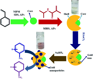 | ||
| Fig. 1 Diagrammatic illustration of the synthesis of the P(STY) latex particles, P(STY@NIPM) microgel particles and Au–P(STY@NIPM) hybrid particles for the catalytic reduction of nitroarenes (4NP). | ||
3.2 Characterization of the microgels and core–shell composite microgels
The P(STY), P(STY@NIPM), and Au–P(STY@NIPM) systems were characterized using several techniques before the use of Au–P(STY@NIPM) as a catalyst for the reduction of the nitro group of the aromatic systems. TEM images of the dispersal of P(STY) latex particles at several resolutions are given in Fig. 2A–C. The TEM images reveal that the P(STY) particles were present as aggregates in the case of their concentrated dispersion due to the hydrophobic interactions between the particles. A P(STY) particle has more affinity toward another P(STY) particle and tries to remain in its vicinity. That is why the P(STY) particles joined with each other to form a chain in aqueous medium. It is worth mentioning that the P(STY) particles were not joined with each other via any chemical interaction. Upon dilution, the chain of particles was broken and the P(STY) particles existed independently. That is why we were able to fabricate P(STY@NIPM) core–shell particles using a dilute dispersion of P(STY) particles as seeds. The P(STY) particles were found to be perfectly spherical in shape with a mean diameter of 76 ± 3 nm, as shown in Fig. 2C. The dispersion of seed particles was diluted before the fabrication of the shell around them. TEM images of the diluted dispersal of Au–P(STY@NIPM) particles are shown in Fig. 2D–F. No particle aggregation was seen in the case of Au–P(STY@NIPM) hybrid microgel particles in contrast to P(STY) particles because the P(NIPAM) shell formed around the P(STY) particles had more affinity toward water compared to the naked P(STY) particles. The TEM images shown in Fig. 2A–F reveal that the mean diameter of the P(STY@NIPM) particles (88 ± 3 nm) was greater than that of the P(STY) particles (76 ± 3 nm), which was a clear indication of the formation of a shell around the P(STY) particles. Although the core–shell morphology of P(STY@NIPM) particles could not be clearly seen in the TEM images, the difference in the diameters of the P(STY) and P(STY@NIPM) particles was sufficient to support the claim. The particle encapsulated in the blue circle in Fig. 2E shows a Au–P(STY@NIPM) particle, while the small dots encapsulated in red circles are Au nanoparticles. Au nanoparticles were present in the outer/shell region of the P(STY@NIPM) particles. A few Au nanoparticles were also located at the outside of the polymeric network, which indicated a reduction of the metal ions outside the microgel particles. The presence of Au nanoparticles outside the P(STY@NIPM) particles may be avoided by performing dialysis of the metal ions into the P(STY@NIPM) particles dispersion before reduction or by performing dialysis of the hybrid microgels using a suitable macromolecular porous membrane. The estimated mean diameter of the nearly spherical Au nanoparticles loaded into P(STY@NIPM) particles was found to be 8 ± 5 nm.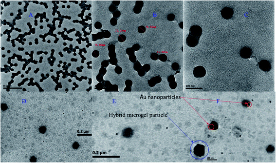 | ||
| Fig. 2 (A–C) TEM images of P(STY) particles at different resolutions and (D–F) TEM images of Au–P(STY@NIPM) particles. | ||
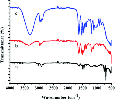
FTIR spectra of the P(STY) core, P(STY@NIPM), and Au–P(STY@NIPM) systems are shown in Fig. 3. The spectrum of P(STY@NIPM) was almost similar to that of Au–P(STY@NIPM), which shows that the filling of Au NPs in the shell of the microgels did not affect the structural arrangement of the polymer microgel network. Spectral peaks of the stretching vibrations of N–H bond of the amide groups appearing at 3348.52 cm−1 and of the C–H bonds of alkyl groups appearing at 2972.50 cm−1 were present in the FTIR spectra of both the pure and hybrid microgels. The presence of the carbonyl group peak at 1626.66 cm−1 was noted in all the spectra. The peak at 3348.52 cm−1 was more prominent in the case of P(STY@NIPM) and Au–P(STY@NIPM) in comparison to P(STY) due to the increase in content of NIPM in the system. The FTIR spectra showed the presence of all the peaks in the microgel and hybrid microgel at the same positions, which indicated that the functionalities of the microgel system remained the same after the fabrication of Au NPs into the microgel system.
Endowment of Au NPs in the P(STY@NIPM) microgels was also verified by the UV-Vis spectra of dilute dispersions of the P(STY), P(STY@NIPM), and Au–P(STY@NIPM) systems shown in Fig. 4. The UV-Vis spectra of P(STY) and P(STY@NIPM) had no prominent peaks in the visible region, while that of dispersion of Au–P(STY@NIPM) gave a prominent peak at 521 nm, which was associated with the λSPR of the Au nanoparticles existing in the microgel system. The UV-Vis spectrum of the Au–P(STY@NIPM) system does not only indicate the formation of Au nanoparticles in the polymer network but also gives some information about the shape and size distribution of Au nanoparticles loaded into the microgel system.47 The single surface plasmon resonance peak indicated the occurrence of spherical Au nanoparticles in the microgel dispersion.
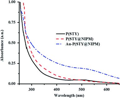 | ||
| Fig. 4 UV-Vis spectra of dilute aqueous dispersions of P(STY) (black solid line), P(STY@NIPM) (dash red line), and Au–P(STY@NIPM) (dash dot blue line) particles at 25 °C. | ||
Au nanoparticles loaded into the P(STY@NIPM) system were found to be stable over the studied time because of the donation of an electron pair by the amide and carbonyl groups of NIPM to the Au metal. The stability of Au NPs in P(STY@NIPM) microgels was studied by UV-visible spectroscopic analysis of a dispersion of Au–P(STY@NIPM) stored in the dark. No shift in surface plasmon resonance wavelength was observed with the time of storage, which indicated that the Au nanoparticles were stable in the microgel dispersion (Fig. 5). Moreover, no change in color of the Au–P(STY@NIPM) dispersion stored in the dark was observed over the studied time, which was also an indication of the stability of the Au nanoparticles in the P(STY@NIPM) dispersion.
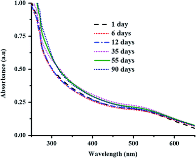 | ||
| Fig. 5 UV-Vis spectra of Au–P(STY@NIPM) dispersion stored in the dark as a function of time of storage at 25 °C. | ||
3.3 Catalytic activity of the Au–P(STY@NIPM) hybrid microgels
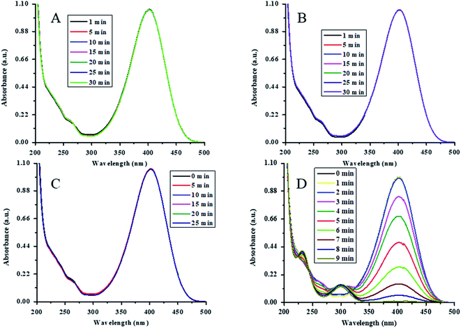
The catalytic action of Au-(STY@NIPM) was initially tested by the reduction of 4NP into 4AP using NaBH4 as a reductant in water. For the confirmation and identification of the true catalyst, various controlled experiments were performed. The reduction of 4NP was carried out in the presence of both P(STY@NIPM) and NaBH4, NaBH4 alone, Au–P(STY@NIPM) alone, and NaBH4 in the presence of the Au–P(STY@NIPM) catalyst at room temperature (26 °C). For all the experiments, the final concentrations of 4NP, NaBH4, P(STY@NIPM), and Au–P(STY@NIPM) were kept constant at 0.057 mM, 3.55 mM, 2.4 mg mL−1, and 2.4 mg mL−1 respectively. For this purpose, 2.00 mL (0.1 mM) of 4NP, 1.5 mL (23.26 mM) of NaBH4, and 2.4 μg mL−1 of Au–P(STY@NIPM) catalyst were mixed in a cuvette to scan the UV-visible spectra of the proceeding reaction in the wavelength range of 200–500 nm. Initially, only a single peak at 400 nm, corresponding to 4-nitrophenolate ions, was observed. No conversion of 4NP to 4AP was observed in the presence of P(STY@NIPM) with NaBH4 (Fig. 6A), NaBH4 alone (Fig. 6B), or Au–P(STY@NIPM) alone (Fig. 6C), but 4NP was reduced rapidly in the presence of Au–P(STY@NIPM) and NaBH4, as shown in Fig. 6D. The fact there was no change in the absorbance of the mixture of P(STY@NIPM) and NaBH4 at 400 nm with time indicated that P(STY@NIPM) was not a true catalyst and NaBH4 could not reduce 4NP in the presence of P(STY@NIPM). The fact there was no change in the absorbance of the mixture of 4NP and NaBH4 at 400 nm showed that NaBH4 could not reduce 4NP in the absence of a suitable catalyst. So the conversion of 4NP to 4AP was kinetically restricted and the presence of a suitable nanocatalyst was necessary for the rapid reduction of 4NP, as reported previously.48 Fig. 6C indicates that the adsorption of 4NP on P(STY@NIPM) particles did not cause any significant change in the absorbance of the mixture of 4NP and P(STY@NIPM). Moreover, the decrease in the absorbance of the mixture of 4NP, NaBH4, and Au–P(STY@NIPM) was not due to the adsorption of 4NP on hybrid particles. The cause for the rapid decrease in absorbance at 400 nm was in fact due to the conversion of 4NP to 4AP. The simultaneous rise in absorbance at 298 nm (λmax of 4AP) along with the reduction in absorbance at 400 nm verified the conversion of 4NP to 4AP. The complete disappearance of the λmax of 4NP indicated the completion of the reduction of 4NP. The reduction was completed within 9 min. The controlled experiments showed that Au NPs loaded into P(STY@NIPM) were real catalysts. 4NP was reduced to 4AP by NaBH4 on the Au nanoparticles' surface loaded in P(STY@NIPM).Au nanoparticles are stable nanoparticles within the polymer microgel system and a very high range of organic reactions can be catalyzed using Au nanoparticles.49 Therefore, herein, we fabricated Au nanoparticles in P(STY@NIPM) microgels for catalytic applications. The catalytic reduction of 4NP is shown in Fig. 6D.
A pseudo-first-order kinetic equation was applied for determining the rate constant for the reductive reaction of 4NP using Au–P(STY@NIPM) and NaBH4. Initially, the reaction did not take place and the absorbance at 400 nm remained constant for some time, called the induction period (τ0), which is a characteristic of nanocatalysis/heterogeneous catalysis.50 This may be attributed to the time required for the reactant molecules to reach the surface of the Au NPs loaded into P(STY@NIPM). The catalytic reductive reaction of 4NP was performed under diverse reaction conditions, and it was found that the value of τ0 decreased at higher concentration of the catalyst, NaBH4, and 4NP.51
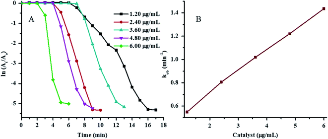
The plots of ln(At/A0) vs. time for 4NP reduction in the presence of various concentrations of Au–P(STY@NIPM) at constant temperature, NaBH4 concentration, and 4NP concentration are shown in Fig. 7A. The value of τ0 was found to decrease with the increase in Au–P(STY@NIPM) content due to the decrease in distance between the reacting molecules present in solution and the Au–P(STY@NIPM) particles. A short time was needed for the reacting molecules to reach the Au surface in the case of a high Au–P(STY@NIPM) concentration. After τ0, the ln(At/A0) value started to decrease with time linearly due to the conversion of 4NP to 4AP according to the pseudo-first-order kinetic equation and became independent of time upon the reaction completion. The value for the apparent rate constant (kob) was evaluated from the gradient of the linear region of ln(At/A0) vs. time after the induction period but before reaction completion. The values of kob corresponding to the half-life period (t1/2), induction period (τ0), and reaction completion time (tc) are shown in Table 1.
| Reaction conditions | NaBH4 (mM) | Catalyst (μg mL−1) | 4NP (mM) | T (°C) | τ0 (min) | tc (min) | kob (min−1) | t1/2 (min) |
|---|---|---|---|---|---|---|---|---|
| NaBH4 | 1.19 | 2.40 | 0.057 | 26 | 15 | 34 | 0.04 | 17.32 |
| 1.97 | 2.40 | 0.057 | 26 | 6 | 25 | 0.12 | 5.77 | |
| 2.66 | 2.40 | 0.057 | 26 | 5 | 12 | 0.91 | 0.76 | |
| 3.55 | 2.40 | 0.057 | 26 | 3 | 9 | 1.12 | 0.62 | |
| 4.34 | 2.40 | 0.057 | 26 | 7 | 15 | 0.56 | 1.24 | |
| 5.13 | 2.40 | 0.057 | 26 | 5 | 14 | 0.54 | 1.28 | |
| 5.92 | 2.40 | 0.057 | 26 | 4 | 14 | 0.45 | 1.54 | |
| 6.71 | 2.40 | 0.057 | 26 | 5 | 18 | 0.29 | 2.39 | |
| Catalyst | 3.55 | 1.20 | 0.057 | 26 | 6 | 16 | 0.55 | 1.26 |
| 3.55 | 2.40 | 0.057 | 26 | 3 | 9 | 0.96 | 0.72 | |
| 3.55 | 3.60 | 0.057 | 26 | 7 | 12 | 1.02 | 0.68 | |
| 3.55 | 4.80 | 0.057 | 26 | 4 | 9 | 1.12 | 0.62 | |
| 3.55 | 6.00 | 0.057 | 26 | 2 | 6 | 1.44 | 0.48 | |
| 4NP | 2.66 | 2.40 | 0.040 | 26 | 10 | 18 | 0.35 | 1.98 |
| 2.66 | 2.40 | 0.045 | 26 | 7 | 16 | 0.51 | 1.36 | |
| 2.66 | 2.40 | 0.051 | 26 | 6 | 14 | 0.54 | 1.28 | |
| 2.66 | 2.40 | 0.054 | 26 | 6 | 14 | 0.69 | 1.00 | |
| 2.66 | 2.40 | 0.057 | 26 | 4 | 9 | 1.12 | 0.62 | |
| 2.66 | 2.40 | 0.060 | 26 | 2 | 13 | 0.38 | 1.82 | |
| 2.66 | 2.40 | 0.063 | 26 | 2 | 18 | 0.26 | 2.67 | |
| Temperature | 2.66 | 2.40 | 0.057 | 24 | 4 | 12 | 0.59 | 1.18 |
| 2.66 | 2.40 | 0.057 | 28 | 3 | 10 | 0.66 | 1.05 | |
| 2.66 | 2.40 | 0.057 | 32 | 1 | 6 | 0.88 | 0.79 | |
| 2.66 | 2.40 | 0.057 | 36 | 1 | 6 | 1.01 | 0.69 | |
| 2.66 | 2.40 | 0.057 | 40 | 2 | 5 | 1.47 | 0.47 |
The value of kob was found to be linearly dependent on the Au–P(STY@NIPM) content (Fig. 7B), which is an indication of a reaction occurring on the surface of Au nanoparticles.
The value of τ0 was found to decrease with the increase in NaBH4 concentration in the reaction vessel. The increase in NaBH4 concentration resulted in an increase in hydrogen bubbling, which increases the transport of reacting molecules toward the surface of the Au NPs loaded into P(STY@NIPM). That is why the time required for the reactants to reach the Au surface decreased. The values of tc and kob decreased with increasing the concentration of NaBH4 up to a specific concentration and then started to decrease again, as shown in Fig. S2A† (Table 1). When the concentration of NaBH4 was kept at less than 1.187 mM or greater than 9.071 mM, then the reduction of 4NP (0.057 mM) in the presence of Au–P(STY@NIPM) (2.40 mg mL−1) took several hours instead of minutes.
The effect of the NaBH4 concentration on the kob value is given in Fig. S2B.† The value of kob increased initially due to a rapid adsorption of the reductant on the Au surface upon the increase in NaBH4 concentration, which resulted in an increase in the reduction rate. The decline in kob value in the [NaBH4] ≥ 9.07 mM region was due to the unavailability of the catalyst sites for the adsorption of 4NP on Au nanoparticles because all the sites were occupied by the reductant under the high concentration of NaBH4 as reported previously.52
To study the effect of 4NP on its reduction, the concentrations of the catalyst and NaBH4 were kept constant while the concentration of 4NP was varied. The reaction completion time was found to increase initially till 0.057 mM 4NP and then started to decrease upon further increase in 4NP molarity, as shown in Fig. S3A.† When the concentration of 4NP was increased from 0.040 to 0.057 mM, then increases in the kob and tc values were observed. Declines in the tc and kob values at [4NP] > 0.057 mM were also noted. Interestingly, at [4NP] ≥ 0.068, the reduction of 4NP was not found to occur, even after 32 min.
3.4 Thermodynamic aspects of the reduction reaction
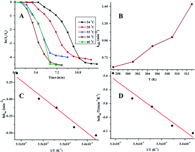
To determine the effect of temperature on the reaction rate, the catalytic reductive reaction of 4NP was performed at diverse values of temperature while keeping the other parameters constant. In order to determine the value of kob at different values of temperature, a plot of ln(At/A0) vs. time at variable values of temperature is presented in Fig. 8A. The values of kob for the reductive catalysis of 4NP at various temperature of medium are presented in Table 1. The effect of temperature on kob is shown in Fig. 8B. In order to evaluate the Arrhenius parameters, the plot of ln![[thin space (1/6-em)]](https://www.rsc.org/images/entities/char_2009.gif) kob against 1/T is given in Fig. 8C. From Fig. 8C, it is clear that the reductive reaction of 4NP in the presence of Au–P(STY@NIPM) hybrid polymer particles obeyed an Arrhenius behavior in the temperature range of 24–40 °C below the volume phase transition temperature (VPTT) of the P(STY@NIPM) system.
kob against 1/T is given in Fig. 8C. From Fig. 8C, it is clear that the reductive reaction of 4NP in the presence of Au–P(STY@NIPM) hybrid polymer particles obeyed an Arrhenius behavior in the temperature range of 24–40 °C below the volume phase transition temperature (VPTT) of the P(STY@NIPM) system.
The value of kob increased from 0.59 to 1.47 min−1 as the temperature of the reaction mixture was raised from 24 to 40 °C for the reduction of 4NP. This rise in kob value with temperature is credited to the rise in the fraction of molecules with K.E. ≥ Ea, whereby high kinetic energy molecules diffused more rapidly from the bulk region to the gold nanoparticles surface region through the polymeric network of P(STY@NIPM) system. With the rise in temperature, the number of reactant molecules having an energy more than Ea increased, which resulted in an increase in kob and the catalytic reduction reaction followed a typical Arrhenius behavior between 24 and 40 °C. Using the Arrhenius eqn (1), Ea was calculated for the reduction of 4NP from the slope of the ln![[thin space (1/6-em)]](https://www.rsc.org/images/entities/char_2009.gif) kob vs. 1/T plot.
kob vs. 1/T plot.
 | (1) |
 | (2) |
| Kinetics/thermodynamic parameters | Value |
|---|---|
| Ea (kJ mol−1) | 43.63 |
| A (min−1) | 2.84 |
| ΔH* (kJ mol−1) | 45.03 |
| ΔS* (kJ mol−1 K−1) | −0.47 |
The positive value of the activation enthalpy showed that the formation of the activated complex from the reactants during the catalytic reduction of 4NP was an endothermic process. The ΔS* value for the catalytic reduction of 4NP was found to be −0.47 kJ mol−1 K−1. These results indicated that the reduction of 4NP in the presence of Au–P(STY@NIPM) hybrid microgels was more favorable at high temperature.53
3.5 Catalytic reduction of other nitroarenes
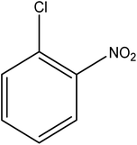
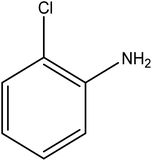
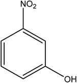
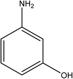
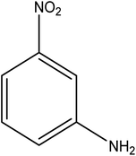
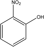
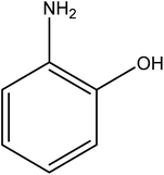
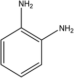
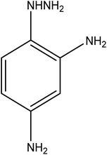
The catalytic reductive reaction of various substituted nitroarenes, such as 2NP, 3NP, 2NA, 3NA, 4NA, 4CNB, 4NPH, and 2,4DNPH, was performed using Au–P(STY@NIPM) as a catalyst in aqueous medium, as shown in Table 3 and Fig. S1A–H.† It was observed that the nitroarenes containing an electron-withdrawing group could be reduced more easily in comparison to nitroarenes containing electron-donating groups. The nitroarenes containing various groups were reduced in the order: Ar-Cl > Ar-OH > Ar-NH2 > Ar-NHNH2, because Cl is a more electron-withdrawing group compared to OH, NH2, and NHNH2. This order of electron-withdrawing effect is in accordance with the inductive and mesomeric effect. When the catalytic reduction of isomeric nitroarenes was carried out, then the ease of reduction was observed in the order: para > ortho > meta.3.6 Mechanism for the reduction of nitroarenes
The kinetic data presented in Section 3.3 suggested that the reductive catalytic reaction of nitroarenes using Au nanoparticles loaded P(STY@NIPM) microgel particles followed a “Langmuir–Hinshelwood mechanism”. According to this mechanism, both reactants (nitroarene and hydrogen coming from NaBH4) diffuse from the aqueous medium to the surface of Au nanoparticles through the crosslinked polymeric network, and then get adsorbed on the surface of Au nanoparticles and converted to products, and then the products are desorbed from the surface of the Au nanoparticles. The proposed mechanism for the catalytic reduction of nitroarenes with Au nanoparticles loaded into P(STY@NIPM) microgels is given in Fig. 10. At first, NaBH4 produced hydrogen gas and B(OH)4−1 in water. The molecular hydrogen and nitroarenes migrated from the bulk region to the surface of Au nanoparticles through the crosslinked polymeric network system.54 At the surface of the Au nanoparticles, hydrogen is attached and interactions are generated between the electron-deficient nitro groups of the nitroarenes and molecular hydrogen, as shown in part a of Fig. 9. Then, the sigma bond present between nitrogen and hydrogen atoms is broken and a new bond is formed between hydrogen and the negative charge containing oxygen atoms to form b and c. In the next step, hydrogen make a new sigma bond with the nitrogen atom and the old sigma bond present between the nitrogen and oxygen atom of the hydronium ion is broken to form d. Finally, d gives the final product (water and aminoarene). These products detach from the surface of Au nanoparticles and migrate from the surface of the nanoparticles to outside the polymer network.55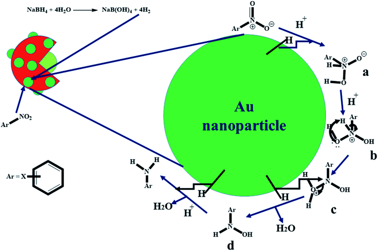 | ||
| Fig. 9 Proposed catalytic reduction mechanism of nitroarenes by NaBH4 in the presence of Au nanoparticles loaded onto P(STY@NIPM) in aqueous medium. | ||
3.7 Catalytic reduction recycling process
The recycling ability of Au–P(STY@NIPM) was investigated using the catalytic reductive reaction of 4NP as a model reaction. After completion of a cycle of reduction of 4NP, the Au–P(STY@NIPM) system was recovered by centrifugation. The recovered catalyst was utilized again for the reductive reaction of 4NP under identical reaction conditions. The value of kob was determined for each cycle. The percentage catalytic activity of the Au–P(STY@NIPM) catalyst was calculated using eqn (3).
 | (3) |
The percentage catalytic activity of the Au–P(STY@NIPM) system as a function of the recycling number is given in Fig. 10. No significant decline in percentage activity was noticed upon the increase in the number of cycles. The catalytic activity of the Au–P(STY@NIPM) catalyst was reduced to only 85% after 5 cycles. The slight decline in percentage activity may be due to a loss of the catalyst content during the centrifugation and decantation steps involved in the recycling process.
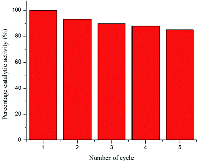 | ||
| Fig. 10 Recycling of the Au–P(STY@NIPM) catalyst used for 4NP reduction [conditions: concentration of 4NP = 0.057 mM, Au–P(STY@NIPM) = 6.00 μg mL−1, NaBH4 = 3.55 mM]. | ||
4. Conclusion
Nearly monodisperse P(STY) and P(STY@NIPM) particles were obtained using a precipitation polymerization in aqueous medium. Au nanoparticles were successfully incorporated into the shell of P(STY@NIPM) microgels. The Au–P(STY@NIPM) particles were found to be an efficient catalyst for the reduction of nitroarenes. Au–P(STY@NIPM) could be used as catalyst for the rapid reduction of all types of nitroarenes into their corresponding aminoarenes in aqueous medium under mild conditions. Nitroarenes that have electron-withdrawing group/s in their structure/s were reduced more rapidly than those with electron-donating group/s. The Au–P(STY@NIPM) catalytic system was found to be easily recyclable, owing to its solid polystyrene core within a crosslinked shell, without any significant loss of activity.Data availability
The data that support the findings of this study are available from the corresponding author upon reasonable request.Conflicts of interest
Authors declare no conflict of interest.Acknowledgements
Funding from various sources including HEC, Pakistan (No. 20-3995/NRPU/R&D/HEC/14/1212) and PU, Lahore (No: D/72/EST.I for fiscal year of 2021–2022) and King Khalid University, Saudi Arabia (R.G.P.1/110/42) is highly acknowledged by the authors.References
- P. J. Landrigan, R. Fuller, S. Fisher, W. A. Suk, P. Sly, T. C. Chiles and S. B. Reilly, Sci. Total Environ., 2019, 650, 2389–2394 CrossRef CAS PubMed.
- S. Bolisetty, M. Peydayesh and R. Mezzenga, Chem. Soc. Rev., 2019, 48, 463–487 RSC.
- M. Ismail, K. Akhtar, M. I. Khan, T. Kamal, M. A. Khan, A. M. Asiri, J. Seo and S. B. Khan, Curr. Pharm. Des., 2019, 25, 3645–3663 CrossRef CAS PubMed.
- A. Trajanov, V. Kuzmanovski, B. Real, J. M. Perreau, S. Džeroski and M. Debeljak, Environ. Sci. Pollut. Res., 2018, 25, 18781–18792 CrossRef CAS PubMed.
- G. Matafonova and V. Batoev, Water Res., 2018, 132, 177–189 CrossRef CAS PubMed.
- P.-E. Mellander, P. Jordan, M. Bechmann, O. Fovet, M. M. Shore and N. T. McDonald, Sci. Rep., 2018, 8, 944 CrossRef PubMed.
- E. G. Nagato and K. Hayakawa, Environ. Pollut., 2019, 250, 554–558 CrossRef CAS PubMed.
- F. Ma, G. Yuan, L. Meng, Y. Oda and J. Hu, Chemosphere, 2012, 88, 476–483 CrossRef CAS PubMed.
- C. Gunanathan, Y. Ben-David and D. Milstein, Sci, 2007, 317, 790–792 CrossRef CAS PubMed.
- C. Kuş, G. Ayhan-Kilcigil, S. Özbey, F. B. Kaynak, M. Kaya, T. Çoban and B. Can-Eke, Bioorg. Med. Chem., 2008, 16, 4294–4303 CrossRef PubMed.
- G. Ćirić-Marjanović, M. Milojević-Rakić, A. Janošević-Ležaić, S. Luginbühl and P. Walde, Chem. Pap., 2016, 71, 199–242 CrossRef PubMed.
- V. Froidevaux, C. Negrell, S. Caillol, J.-P. Pascault and B. Boutevin, Chem. Rev., 2016, 116, 14181–14224 CrossRef CAS PubMed.
- J. Qiu, B. Tang, B. Ju, Y. Xu and S. Zhang, Dyes Pigm., 2017, 136, 63–69 CrossRef CAS.
- R. Kawahara, K. Fujita and R. Yamaguchi, Adv. Synth. Catal., 2011, 353, 1161–1168 CrossRef CAS.
- K. Junge, K. Schröder and M. Beller, Chem. Commun., 2011, 47, 4849–4859 RSC.
- H.-U. Blaser, C. Malan, B. Pugin, F. Spindler, H. Steiner and M. Studer, Adv. Synth. Catal., 2003, 345, 103–151 CrossRef CAS.
- S. Shylesh, V. Schünemann and W. R. Thiel, Angew. Chem., Int. Ed., 2010, 49, 3428–3459 CrossRef CAS PubMed.
- P. Zhao, X. Feng, D. Huang, G. Yang and D. Astruc, Coord. Chem. Rev., 2015, 287, 114–136 CrossRef CAS.
- K. Tsutsumi, F. Uchikawa, K. Sakai and K. Tabata, ACS Catal., 2016, 6, 4394–4398 CrossRef CAS.
- J. Li, L. Zhang, X. Liu, N. Shang, S. Gao, C. Feng, C. Wang and Z. Wang, New J. Chem., 2018, 42, 9684–9689 RSC.
- R. Grzeschik, D. Schäfer, T. Holtum, S. Küpper, A. Hoffmann and S. Schlücker, J. Phys. Chem. C, 2020, 124, 2939–2944 CrossRef CAS.
- Y. Jang, S. Kim, S. W. Jun, B. H. Kim, S. Hwang, I. K. Song, B. M. Kim and T. Hyeon, Chem. Commun., 2011, 47, 3601–3603 RSC.
- E. Kim, H. S. Jeong and B. M. Kim, Catal. Commun., 2014, 45, 25–29 CrossRef CAS.
- S. Ikeda, S. Ishino, T. Harada, N. Okamoto, T. Sakata, H. Mori, S. Kuwabata, T. Torimoto and M. Matsumura, Angew. Chem., Int. Ed., 2006, 118, 7221–7224 CrossRef.
- H. Lu, Z. Geng, J. Li, D. Zou, Y. Wu and Y. Wu, Org. Lett., 2016, 18, 2774–2776 CrossRef CAS PubMed.
- Ö. Metin, A. Mendoza-Garcia, D. Dalmizrak, M. S. Gültekin and S. Sun, Catal. Sci. Technol., 2016, 6, 6137–6143 RSC.
- K. Shanmugaraj, T. M. Bustamante, J. N. D. de León, R. Aepuru, R. V. Mangalaraja, C. C. Torres and C. H. Campos, Catal. Today, 2021 DOI:10.1016/j.cattod.2021.09.003.
- Y. Xie, X. Shang, D. Liu, H. Zhao, Y. Gu, Z. Zhang and X. Wang, Appl. Catal., B, 2019, 259, 118087 CrossRef CAS.
- A. Saha and B. Ranu, J. Org. Chem., 2008, 73, 6867–6870 CrossRef CAS PubMed.
- R. Dey, N. Mukherjee, S. Ahammed and B. C. Ranu, Chem. Commun., 2012, 48, 7982–7984 RSC.
- X. Y. Dong, Z. W. Gao, K. F. Yang, W. Q. Zhang and L. W. Xu, Catal. Sci. Technol., 2015, 5, 2554–2574 RSC.
- K. Zhang, J. M. Suh, J. W. Choi, H. W. Jang, M. Shokouhimehr and R. S. Varma, ACS Omega, 2019, 4, 483–495 CrossRef CAS PubMed.
- W. Zhan, Y. Shu, Y. Sheng, H. Zhu, Y. Guo, L. Wang, Y. Guo, J. Zhang, G. Lu and S. Dai, Angew. Chem., 2017, 56, 4494–4498 CrossRef CAS PubMed.
- K. Kumari, P. Singh and G. K. Mehrotra, Adv. Energy Mater., 2014, 529–553 CAS.
- L. Wang, Q. Yang, Y. Cui, D. Gao, J. Kang, H. Sun, L. Zhu and S. Chen, New J. Chem., 2017, 41, 8399–8406 RSC.
- D. Ulker, G. Kocak, C. Tuncer and V. Butun, Colloid Polym. Sci., 2019, 297, 1067–1078 CrossRef CAS.
- Y. Dong, Y. Ma, T. Zhai, F. Shen, Y. Zeng, H. Fu and J. Yao, Macromol. Rapid Commun., 2007, 28, 2339–2345 CrossRef CAS.
- Z. Zhai, Q. Wu, J. Li, B. Zhou, J. Shen, Z. H. Farooqi and W. Wu, J. Catal., 2019, 369, 462–468 CrossRef CAS.
- M. Arif, Z. H. Farooqi, A. Irfan and R. Begum, J. Mol. Liq., 2021, 336, 116270 CrossRef CAS.
- S. ur Rehman, A. R. Khan, A. Shah, A. Badshah and M. Siddiq, Colloids Surf., A, 2017, 520, 826–833 CrossRef CAS.
- A. M. Lazim, M. Bradley and J. Eastoe, Langmuir, 2010, 26, 11779–11783 CrossRef PubMed.
- H. Jia, D. Schmitz, A. Ott, A. Pich and Y. Lu, J. Mater. Chem., 2015, 3, 6187–6195 RSC.
- C. Xiao, Q. Wu, A. Chang, Y. Peng, W. Xu and W. Wu, J. Mater. Chem., 2014, 2, 9514–9523 RSC.
- S. Shi, Q. Wang, T. Wang, S. Ren, Y. Gao and N. Wang, J. Phys. Chem. B, 2014, 118, 7177–7186 CrossRef CAS PubMed.
- K. Naseem, R. Begum, W. Wu, A. Irfan, A. G. Al-Sehemi and Z. H. Farooqi, J. Cleaner Prod., 2019, 211, 855–864 CrossRef CAS.
- M. Andersson and S. L. Maunu, J. Polym. Sci., Part B: Polym. Phys., 2006, 44, 3305–3314 CrossRef CAS.
- R. Begum, Z. H. Farooqi, K. Naseem, F. Ali, M. Batool, J. Xiao and A. Irfan, Crit. Rev. Anal. Chem., 2018, 48, 503–516 CrossRef CAS PubMed.
- Z. Yan, L. Fu, X. Zuo and H. Yang, Appl. Catal., B, 2018, 226, 23–30 CrossRef CAS.
- L. Ali Shah, M. Sayed and M. Siddiq, Mater. Sci.-Pol., 2017, 35, 651–659 CrossRef.
- R. D. Neal, Y. Inoue, R. A. Hughes and S. Neretina, J. Phys. Chem. C, 2019, 123, 12894–12901 CrossRef CAS.
- R. Begum, Z. H. Farooqi, E. Ahmed, K. Naseem, S. Ashraf, A. Sharif and R. Rehan, Appl. Organomet. Chem., 2017, 31, 1–8 CrossRef.
- R. Begum, J. Najeeb, G. Ahmad, W. Wu, A. Irfan, A. G. Al-sehemi and Z. H. Farooqi, React. Funct. Polym., 2018, 132, 89–97 CrossRef CAS.
- M. Shahid, Z. H. Farooqi, R. Begum, K. Naseem, M. Ajmal and A. Irfan, Korean J. Chem. Eng., 2018, 35, 1099–1107 CrossRef CAS.
- R. Begum, Z. H. Farooqi, A. H. Aboo, E. Ahmed, A. Sharif and J. Xiao, J. Hazard. Mater., 2019, 377, 399–408 CrossRef CAS PubMed.
- S. Fountoulaki, V. Daikopoulou, P. L. Gkizis, I. Tamiolakis, G. S. Armatas and I. N. Lykakis, ACS Catal., 2014, 4, 3504–3511 CrossRef CAS.
Footnote |
| † Electronic supplementary information (ESI) available. See DOI: 10.1039/d1ra09380k |
| This journal is © The Royal Society of Chemistry 2022 |

