 Open Access Article
All alginate-derived high-performance T-Nb2O5/C//seaweed carbon Li-ion capacitors†
Mingming Li ,
Yan Fang,
Jinghan Li,
Boya Sun,
Jie Du,
Qinglei Liu* and
Di Zhang*
State Key Laboratory of Metal Matrix Composites, School of Materials Science and Engineering, Shanghai Jiao Tong University, Shanghai 200240, China. E-mail: liuqinglei@sjtu.edu.cn; zhangdi@sjtu.edu.cn
First published on 16th February 2022
Abstract
Lithium-ion capacitors (LICs) have attracted intense attention due to their high energy/power densities and good stability. However, their performance is severely limited by the imbalance in reaction kinetics and electrochemical capacity between the faradaic battery-like anodes and non-faradic capacitive cathodes. Here, we propose an all alginate-derived LIC assembled with a three-dimensional porous orthorhombic phase Nb2O5/C hybrid as the anode, seaweed-derived carbon as the cathode and sodium alginate (SA) as the electrode binder. The increase in the rate performance of the anode and the capacity of the cathode efficiently mitigates the mismatch between the counter electrodes, and the SA binder provides facilitated access for Li ions to the surfaces of electrode materials. The all alginate-derived LIC exhibits high energy (143.9 W h kg−1 at 87.6 W kg−1) and power (17.5 kW kg−1 at 75.1 W h kg−1) densities with a superior cyclability (84.6% capacity retention after 3000 charge–discharge cycles), surpassing those of previous Nb2O5-based LICs. This work provides a novel design strategy for the electrodes of next-generation high-performance LICs.
To combat the energy crisis and environmental pollution, large-scale energy storage systems have been rapidly developed and extensively studied.1–4 Lithium-ion capacitors (LICs), a new type of energy storage device, have attracted intense attention of the scientific community5–7 due to their high energy/power densities and good stability. A typical LIC device usually consists of a battery-like anode and a capacitive cathode. In general, the kinetics of the anode using the faradaic redox reaction is much slower than the cathode using physical adsorption/desorption of electrolyte ions,8,9 while its capacity is higher than that of the cathode. Therefore, novel anode and cathode materials that can narrow the gaps of reaction kinetics and electrochemical capacity between the counter electrodes are urgently needed.
As a renewable resource, biomass with highly delicate structures created by nature has become promising electrode material precursors due to the high-accessibility and eco-friendliness, which can effectively solve the serious energy crisis. Seaweed is a kind of brown algae with functional sodium alginate (SA) as the main composition. Carbonized seaweed contains abundant CaO/C nanoparticles due to the crosslinking reaction of SA and calcium ions from seawater.10 After removing CaO, carbon materials with sufficient mesoporous channels and surface areas can be prepared, which are essential for ion migration and adsorption/desorption. Thus, seaweed-derived carbons have great superiority as high-capacity cathodes. In addition, if the SA extracted from seaweed is crosslinked with multivalent cations, nanosized metal or metal oxide/carbon (NM/C) composites with three-dimensional (3D) porous structures can be directly obtained.11–14 The 3D porous structures are beneficial to the fast transport of electrolyte ions, shortening the time for ion migration to the active sites of the composites. Hence, the NM/C composites have the advantage of being high-rate anode materials. Furthermore, researchers found that compared to the common commercial binders such as polyvinylidene difluoride (PVDF), SA can provide facilitated access for ions via Li+ hopping between the adjacent carboxylic cites,15,16 reducing the time for Li+ to reach the surfaces of the electrode materials. Additionally, it enhances the electrode stability as well. Therefore, using SA as electrode binder can further improve the performance of the device.
Orthorhombic phase Nb2O5 (T-Nb2O5) is one of the ideal anode materials for LICs because of its fast pseudocapacitive behavior for Li-ions17–20 and high theoretical specific capacity.21,22 Based on the advantages of seaweed, SA and T-Nb2O5, here, we propose an all alginate-derived LIC assembled with a 3D hierarchical porous T-Nb2O5/carbon hybrid (T-Nb2O5/C) as the anode, a high-temperature carbonized seaweed-derived carbon (T-SDC) as the cathode and SA as the electrode binder. The increase in the rate performance of the anode and the capacity of the cathode efficiently mitigates the mismatch between the counter electrodes of the LIC, and the SA binder provides transport channels of Li-ions to readily reach the electrode surfaces and improve the electrode stability. The assembled LIC exhibits high energy (143.9 W h kg−1 at 87.6 W kg−1) and power (17.5 kW kg−1 at 75.1 W h kg−1) densities with a superior cyclability (84.6% capacity retention after 3000 charge–discharge cycles), surpassing those of ever-reported Nb2O5-based LICs. This work provides a novel and rational strategy for the electrodes design to push the rapid development of next-generation high-performance LICs.
The synthesis process of the all alginate-derived LIC is illustrated in Fig. 1. In brief, firstly, a 1.5 wt% SA aqueous solution was dripped into a 5 wt% NbCl5 solution (volume ratio = 2![[thin space (1/6-em)]](https://www.rsc.org/images/entities/char_2009.gif) :
:![[thin space (1/6-em)]](https://www.rsc.org/images/entities/char_2009.gif) 5) under magnetic stirring for 24 h to form Nb-alginate hydrogel beads. After washing and freeze-drying, the formed Nb-alginate aerogel was carbonized at 700 °C for 2 h under N2 atmosphere to form T-Nb2O5/C hybrid. Secondly, the carbonized seaweed was washed with HCl, activated by KOH and further carbonized at 800 °C to prepare T-SDC. Thirdly, SA was used as electrode binder to prepare T-Nb2O5/C anode (T-Nb2O5/C-SA) and T-SDC cathode (T-SDC-SA). Finally, the all alginate-derived hybrid LIC (T-Nb2O5/C//T-SDC) was assembled with the mass ratio of anode:cathode = 1
5) under magnetic stirring for 24 h to form Nb-alginate hydrogel beads. After washing and freeze-drying, the formed Nb-alginate aerogel was carbonized at 700 °C for 2 h under N2 atmosphere to form T-Nb2O5/C hybrid. Secondly, the carbonized seaweed was washed with HCl, activated by KOH and further carbonized at 800 °C to prepare T-SDC. Thirdly, SA was used as electrode binder to prepare T-Nb2O5/C anode (T-Nb2O5/C-SA) and T-SDC cathode (T-SDC-SA). Finally, the all alginate-derived hybrid LIC (T-Nb2O5/C//T-SDC) was assembled with the mass ratio of anode:cathode = 1![[thin space (1/6-em)]](https://www.rsc.org/images/entities/char_2009.gif) :
:![[thin space (1/6-em)]](https://www.rsc.org/images/entities/char_2009.gif) 3. Control samples of T-Nb2O5/C with PVDF (T-Nb2O5/C-PVDF) anode, T-SDC with PVDF (T-SDC-PVDF) cathode, activated carbon (AC) with SA (AC-SA) cathode and AC with PVDF (AC-PVDF) cathode were prepared in a similar way (more details in the ESI†).
3. Control samples of T-Nb2O5/C with PVDF (T-Nb2O5/C-PVDF) anode, T-SDC with PVDF (T-SDC-PVDF) cathode, activated carbon (AC) with SA (AC-SA) cathode and AC with PVDF (AC-PVDF) cathode were prepared in a similar way (more details in the ESI†).
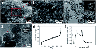
The morphology and microstructure of the T-Nb2O5/C hybrid were characterized by scanning electron microscopy (SEM) and transmission electron microscopy (TEM) as shown in Fig. 2a–d, S2 and S3.† The carboxyl groups in segment of SA can crosslink with Nb5+ to form an “egg-box” structure, and Nb5+ can well match the size of the spatial structure between the segments, so the crosslinked structure is very stable, and form microcrystalline regions inside the gel. During the carbonization process, Nb5+ combines with O to form T-Nb2O5 nanoparticles and uniformly distribute in the carbon matrix. At the same time, the polymer chains in the microcrystalline regions are broken down to carbon chains, which are squeezed to the outside of the nanoparticles accompanied by pyrolysis and shrinkage, and further rearrange to form the graphitic layer. Therefore, the T-Nb2O5/C hybrid exhibits a nanoscale foam structure with 3D interconnected channels (Fig. 2a). The size of these channels in the continuous foam network is 20–100 nm (Fig. 2b), which is beneficial to the fast ion diffusion of the electrolyte. The TEM image in Fig. 2c shows that the whole porous structure is composed of carbon chains uniformly embedded by T-Nb2O5 nanoparticles. The diameter of T-Nb2O5 nanoparticles is 7–10 nm, and they are wrapped by graphitic layers (denoted by red arrows in Fig. 2d). These graphitic carbons can effectively alleviate the volume change of electroactive materials during the cycling process,12,14 preserving the structural integrity of the hybrid. In addition, to further investigate the pore structure of the T-Nb2O5/C, nitrogen adsorption–desorption measurements were used, as shown in Fig. 2e. The isotherm exhibits a typical type-IV curve, and the Brunauer–Emmett–Teller (BET) specific surface area (SSA) of the hybrid is 161.4 m2 g−1 (more details in Table S1†). The pore size distribution in Fig. 2f demonstrates that the hybrid has a hierarchical porous structure including a mass of mesopores with sizes of 2–6 nm, which can provide fast transportation pathways for electrolyte ions to react with the T-Nb2O5 nanoparticles during the charge–discharge process.
The X-ray diffraction (XRD) result of the T-Nb2O5/C is shown in Fig. 3a. The emerging peaks at 2θ ≈ 22.6°, 28.4°, 28.9°, 36.6°, 36.9°, 46.1° in the pattern are assigned to the reflection by the (001), (180), (200), (181), (201) and (002) planes of the orthorhombic crystal structure, respectively. This special orthorhombic phase is beneficial for Li+ to intercalate and extract.23,24 The Raman spectrum in Fig. 3b shows characteristic peaks of both T-Nb2O5 and carbon matrix. The two signals at 580–740 and 200–350 cm−1 are attributed to the Nb–O–Nb bridging bond of distorted NbO6 and Nb–O–Nb angular deformation, respectively.8,25 And other two broad peaks at 1600 (G-band) and 1360 cm−1 (D-band) are assigned to reflections from the carbon materials. The G-band is ascribed to the C–C stretching mode in the basal plane of crystalline micro-graphite, while the D-band corresponds to the response from lattice defects and disordered carbon.26–28 The coexistence of G- and D-band indicates partial graphitization of the carbon structure. In addition, the integrated intensity ratio between the G- and D-band (IG/ID) is calculated to be 1.19, demonstrating a relatively high graphitization degree of the carbon framework in the hybrid, which ensures a good electrical conductivity during electrode reactions.
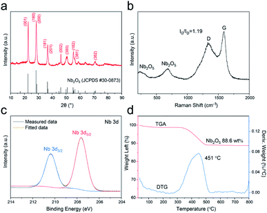 | ||
| Fig. 3 (a) XRD pattern, (b) Raman spectrum, (c) XPS spectrum of Nb 3d and (d) TGA and DTG curves of the T-Nb2O5/C anode. | ||
The chemical states and surface chemical compositions of the T-Nb2O5/C hybrid were elucidated by X-ray photoelectron spectroscopy (XPS) (Fig. 3c and S4†). The peaks of Nb, C and O are obvious in the full spectrum (Fig. S4a†). The Nb 3d XPS spectrum (Fig. 3c) displays two peaks at 207.6 and 210.4 eV, assigned to the Nb 3d5/2 and Nb 3d3/2 spin–orbit states, respectively, revealing that the hybrid only contains Nb5+. In the high-resolution spectrum of C 1s (Fig. S4b†), the curve can be deconvoluted to three sub-peaks. The main peak at 284.7 eV is attributed to sp2-hybridized graphite-like carbon (C–C sp2), and peaks at 286.2 and 289.6 eV are related to the C–O and O–C![[double bond, length as m-dash]](https://www.rsc.org/images/entities/char_e001.gif) O bonds, respectively. The existence of these oxygen-containing groups ensures the wettability of the surface.13 Moreover, the O 1s XPS spectrum (Fig. S4c†) shows a large peak centered at 530.6 eV, corresponding to O–Nb bond, and the other two overlapping peaks at 531.7 and 532.5 eV are respectively ascribed to O
O bonds, respectively. The existence of these oxygen-containing groups ensures the wettability of the surface.13 Moreover, the O 1s XPS spectrum (Fig. S4c†) shows a large peak centered at 530.6 eV, corresponding to O–Nb bond, and the other two overlapping peaks at 531.7 and 532.5 eV are respectively ascribed to O![[double bond, length as m-dash]](https://www.rsc.org/images/entities/char_e001.gif) C and O–C bonds. These results all confirm the robust combination of T-Nb2O5 and SA-derived carbon. Thermogravimetric analysis (TGA) was carried out in air from 25 to 800 °C to measure the weight percentage of T-Nb2O5 in the hybrid. The TGA curve in Fig. 3d displays a weight decrease between 300-550 °C, which is related to the combustion of carbon in the hybrid. Correspondingly, the derivative thermogravimetric (DTG) curve exhibits a broad peak located at 451 °C. The weight percentage of T-Nb2O5 in the hybrid is approximately 88.6 wt%.
C and O–C bonds. These results all confirm the robust combination of T-Nb2O5 and SA-derived carbon. Thermogravimetric analysis (TGA) was carried out in air from 25 to 800 °C to measure the weight percentage of T-Nb2O5 in the hybrid. The TGA curve in Fig. 3d displays a weight decrease between 300-550 °C, which is related to the combustion of carbon in the hybrid. Correspondingly, the derivative thermogravimetric (DTG) curve exhibits a broad peak located at 451 °C. The weight percentage of T-Nb2O5 in the hybrid is approximately 88.6 wt%.
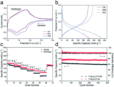
To study the electrochemical performances of the T-Nb2O5/C-SA anode and the T-Nb2O5/C-PVDF anode, they were first tested in half-cells with a scan rate of 0.2 mV s−1 at the voltage window of 1.0–3.0 V before constructing the LICs (Fig. 4 and S5†). As shown in Fig. 4a, two pairs of cathodic/anodic peaks are located at 1.5 and 1.8 V, corresponding to the fast two-dimensional Li+ transport within T-Nb2O5 crystals:17,29 xLi+ + Nb2O5 + xe− ↔ LixNb2O5. After 10 discharge/charge cycles, the cyclic voltammetry (CV) curves of the T-Nb2O5/C-SA electrode are relatively stable. Fig. 4b displays the first three galvanostatic charge–discharge (GCD) curves of the T-Nb2O5/C-SA anode at a current density of 0.1 A g−1. The initial coulombic efficiency (ICE) is 78.1%, and the capacity loss is mainly attributed to the partially irreversible Li+ intercalation occurring in the first cycle. In practical applications, the low ICE can be improved by a pre-lithiation treatment of electrodes. After the first cycle, the discharge and charge curves are well overlapped, demonstrating a high reversible capacity of T-Nb2O5/C-SA. Fig. 4c depicts the rate performance of the T-Nb2O5/C hybrid. The specific capacity of T-Nb2O5/C-SA is 206 mA h g−1 at 0.1 A g−1, and when the current density increases to 5 A g−1, there is still 53.4% retention (110 mA h g−1), much better than the T-Nb2O5/C-PVDF (28.2% retention). This suggests that the highly interconnected mesoporous channels and the sufficiently exposed T-Nb2O5 nanoparticles ensure fast transport and efficient intercalation/extraction of Li ions, respectively. Moreover, Li ions can transport rapidly through the SA binder via hopping between the adjacent carboxylic cites of SA,16 efficiently enhancing the high-rate performance of the hybrid. In addition, the original capacity of T-Nb2O5/C-SA can be recovered after the high-rate tests. The above results show that the as-prepared T-Nb2O5/C-SA electrode has an excellent rate capability. The cycling performance of T-Nb2O5/C hybrid is shown in Fig. 4d. After a slight decrease in the first ten cycles, it exhibits a capacity retention of 97 mA h g−1 after 500 cycles, which is 97.4% of the first cycle capacity (99.6 mA h g−1), exhibiting a better stable cycling performance than the T-Nb2O5/C-PVDF electrode (87.6% retention). Furthermore, the microstructures of the T-Nb2O5/C-SA after cycling test were also tested by TEM, as shown in Fig. S6.† After 100 cycles, the T-Nb2O5 nanoparticles are still uniformly embedded in the carbon framework, which is similar to the elemental distribution before the testing (Fig. S2†), indicating the physical stability of the hybrid structure.
The CV profiles of the T-Nb2O5/C-SA electrode at various scan rates are shown in Fig. S7a.† As the scan rate increases, the potential differences between the anodic and cathodic peaks also increase. In general, the kinetic parameters obtained from CV curves obey the power law:6,25 i = avb, where i is the current (A), v is the potential sweep rate (mV s−1) and a and b are adjustable parameters. The b value is feasible to distinguish the capacitive contribution (b = 1.0) and the diffusion-limited contribution (b = 0.5) in an electrochemical process. Actually, the current (i) can be divided into two parts, including capacitive (k1v) and diffusion-limited (k2v1/2) effects as follows: i = k1v + k2v1/2, where i is the current at a certain potential, v is the scan rate and k1 and k2 are variable parameters. In Fig. S7b,† the b values of the T-Nb2O5/C-SA are 0.81 and 0.82, indicating that the main contribution is the surface-controlled pseudocapacitive behavior. And the capacitive contribution (red region) of T-Nb2O5/C-SA at a scan rate of 0.5 mV s−1 is calculated to be 73.0% (Fig. S7c†), and the maximal capacitive ratio is 93.2% at 2 mV s−1 (Fig. S7d†), demonstrating its fast kinetics. These results all imply that the T-Nb2O5/C-SA possess abundant pathways for ions to transport to T-Nb2O5 surface active sites, resulting in enhanced capacity and rate performance.
Electrochemical impedance spectroscopy (EIS) is used to analyze the charge-transfer characteristics of the hybrid (Fig. S8†). The intersection of the plot of T-Nb2O5/C-SA at the real part Z′, which stands for the internal resistance of the electrode (Rs) is 2.8 Ω, and the charge transfer resistance (Rct) is 57.2 Ω, indicating an excellent electron and charge conductivity. Moreover, the Warburg-type line (the slope of the 45° portion of the curve)30 of the T-Nb2O5/C-SA is shorter than the T-Nb2O5/C-PVDF, demonstrating that the SA binder can diffuse lithium ions faster inside the electrode.
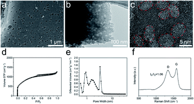
The morphology and microstructure of the T-SDC cathode are shown in Fig. 5a–c and S9.† After activation and further carbonization, the obtained T-SDC has a nanostructure with dense mesopores originated from the CaO/C “egg-box” units. These mesopores can provide transport channels for electrolyte ions. In addition, the SSA of the T-SDC is 3320.7 m2 g−1 (Fig. 5d, more details in Table S1†), indicating that the T-SDC can possess abundant active sites for ions adsorption/desorption. The pore size distribution in Fig. 5e demonstrates that there are many mesopores with sizes of 2–5 nm in the T-SDC, and the calculated IG/ID value in the Raman spectrum in Fig. 5f is 1.06, demonstrating a high graphitization degree of the seaweed-derived carbon, which ensures a good electrical conductivity.
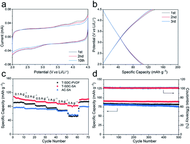
The electrochemical properties of the T-SDC-SA cathode were measured in half-cells with a scan rate of 0.2 mV s−1 at the voltage window of 2.0–4.5 V (Fig. 6a). The rectangular shape of CV curves confirms that the T-SDC-SA cathode operates via non-faradaic capacitive reactions, and the straight lines in GCD curves (Fig. 6b) also indicate its fast capacitive behavior in the electrolyte. In addition, the T-SDC-SA electrode delivers a high specific capacity of 102 mA h g−1 at 0.1 A g−1 (Fig. 6c), higher than the AC-SA (78 mA h g−1). The superior capacity is related to the hierarchical porous structure, which provides more ion adsorption/desorption sites. Moreover, it is worth noting that the electrodes with the SA binder show much better high-rate performances than those based on PVDF binder. Specifically, when the current density increases from 0.1 A g−1 to 5 A g−1, the T-SDC-SA, AC-SA and T-SDC-PVDF cathodes exhibit 81.4%, 78.9% and 64.7% retention in capacity, respectively, and this is also attributed to the efficient diffusion of Li ions in the SA binder. The cycling performance in Fig. 6d shows a 98.2% retention in capacity for the T-SDC-SA after 500 cycles, and the surface binding between the T-SDC and the SA via carboxyl groups might be responsible for the excellent stability of the electrode.12 The Rct of the T-SDC-SA electrode is 32.2 Ω, and its Warburg-type line is the shortest (Fig. S11c†), demonstrating fast Li-ions diffusion inside the electrode.
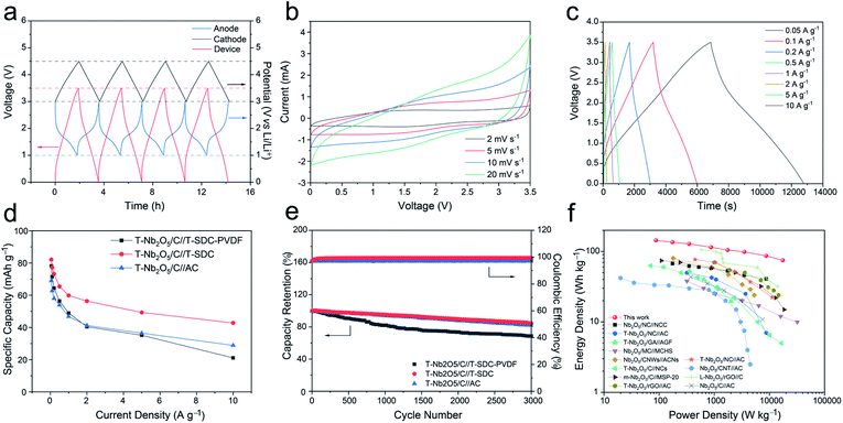
An all alginate-derived T-Nb2O5/C//T-SDC LIC was assembled based on the T-Nb2O5/C hybrid anode, the T-SDC cathode and SA electrode binder. For comparison, T-Nb2O5/C//T-SDC-PVDF LIC (PVDF as the binder) and T-Nb2O5/C//AC LIC (AC as the cathode and SA as the binder) were also assembled. The T-Nb2O5/C anode was pre-activated at 0.1 A g−1 for 10 cycles. Fig. 7a shows the initial four GCD cycles at 50 mA g−1 of the T-Nb2O5/C//T-SDC LIC and the corresponding potential variation of the anode and cathode. At the end of the charge and discharge, the cathode and anode can achieve their upper potential limit (3.0 V vs. Li/Li+ for T-Nb2O5/C, 4.5 V vs. Li/Li+ for T-SDC), respectively, indicating the good match between the counter electrodes.31 Fig. 7b shows asymmetric CV curves without obvious redox peaks of the T-Nb2O5/C//T-SDC at various scan rates from 2 to 20 mV s−1, indicating the well-matched kinetics of fast intercalation reactions at the anode and rapid electrolyte ion adsorption/desorption at the cathode. The GCD profiles in Fig. 7c exhibit a non-classical and asymmetrical triangular shape, in agreement with the results of the CV measurements. Furthermore, the rate performance in Fig. 7d demonstrates that the T-Nb2O5/C//T-SDC possesses better high-rate capability than the T-Nb2O5/C//T-SDC-PVDF and T-Nb2O5/C//AC LIC, which is related to the fast ions diffusion in the SA binder and the rapid ion transport in the mesoporous channels of the T-SDC, respectively. In addition, the good capacity retention (84.6% after 3000 cycles at 1 A g−1) and the high coulombic efficiency (with an average value of 99.7%) in Fig. 7e both reveal an excellent stability of the T-Nb2O5/C//T-SDC LIC.
Ragone plots of the all alginate-derived T-Nb2O5/C//T-SDC LIC are shown in Fig. 7f. Both the power density and energy density are calculated based on the total mass of active materials of electrodes. The device exhibits a high energy density of 143.9 W h kg−1 at 87.6 W kg−1, and even can deliver 75.1 W h kg−1 at a high power density of 17.5 kW kg−1, surpassing those of previous T-Nb2O5-based (more details in Table S2†)7,8,25,29,32–39 and other metal oxide-based LICs (Fig. S13 and Table S3†). The excellent electrochemical performances should be ascribed to the well-matched reaction kinetics and electrochemical capacity of the counter electrodes, and the good Li-ions diffusion of the SA binder. First, the highly porous structure of the T-Nb2O5/C hybrid provides abundant pathways for electron mobility and mass transport during the electrochemical reaction, and the well-defined nanosized T-Nb2O5 particles shorten the Li+ diffusion and electron transportation lengths, resulting in rapid charge transport. Second, graphitic layers effectively buffer the volume change of T-Nb2O5 nanoparticles during the cycling process and enhance the electrical conductivity of the hybrid. Third, the large SSA of the T-SDC ensures sufficient adsorption/desorption of the electrolyte ions, increasing the specific capacity of the cathode. Fourth, the mesoporous channels of the T-SDC guarantee fast transport of Li ions, possessing a good rate performance. Last, the SA binder provides transport channels of Li+ to the electrode surfaces, and enhances the stability of the electrode.
In summary, we report a high-performance T-Nb2O5/C//T-SDC LIC assembled with an alginate resource as the anode, cathode and electrode binder. The increase in the rate performance of the T-Nb2O5/C anode and the capacity of the T-SDC cathode efficiently reduces the mismatch between the counter electrodes. Using SA as the electrode binder, which can provide facilitated access of Li+ to readily reach the electrode surfaces, the all alginate-derived T-Nb2O5/C//T-SDC LIC exhibits high energy density (143.9 W h kg−1 at 87.6 W kg−1), high power density (17.5 kW kg−1 at 75.1 W h kg−1) and excellent stability (84.6% capacity retention after 3000 cycles at 1 A g−1). This work provides a novel design strategy for the electrodes of next-generation high-performance LICs.
Conflicts of interest
There are no conflicts to declare.Acknowledgements
This work was supported by National Natural Science Foundation of China (No. 52072241 and 51772187); Shanghai Science and Technology Committee (No. 18JC1410500). We also acknowledge the Open Project of State Key Laboratory of Metal Matrix Composites.References
- P. Simon and Y. Gogotsi, Nat. Mater., 2008, 7(11), 845–854 CrossRef CAS PubMed.
- J. Liu, Y. Cai, H. Pang, B. Cao, C. Luo, Z. Hu, C. Xiao, H. Zhang, F. Lv, Y. Cao and L. Yu, Chin. Chem. Lett., 2021 DOI:10.1016/j.cclet.2021.12.068.
- J. Liu, Y. Cai, C. Xiao, H. Zhang, F. Lv, C. Luo, Z. Hu, Y. Cao, B. Cao and L. Yu, Ind. Eng. Chem. Res., 2019, 58(44), 20491–20494 CrossRef CAS.
- H. Liu, X. Liu, S. Wang, H.-K. Liu and L. Li, Energy Storage Materials, 2020, 28, 122–145 CrossRef.
- B. Deng, T. Lei, W. Zhu, L. Xiao and J. Liu, Adv. Funct. Mater., 2018, 28(1), 1704330 CrossRef.
- S. Fu, Q. Yu, Z. Liu, P. Hu, Q. Chen, S. Feng, L. Mai and L. Zhou, J. Mater. Chem. A, 2019, 7(18), 11234–11240 RSC.
- Y. Lian, Z. Xu, D. Wang, Y. Bai, C. Ban, J. Zhao and H. Zhang, J. Alloys Compd., 2021, 850, 156808 CrossRef CAS.
- E. Lim, H. Kim, C. Jo, J. Chun, K. Ku, S. Kim, H. I. Lee, I.-S. Nam, S. Yoon, K. Kang and J. Lee, ACS Nano, 2014, 8(9), 8968–8978 CrossRef CAS PubMed.
- Y. Wang, Z. Hong, M. Wei and Y. Xia, Adv. Funct. Mater., 2012, 22(24), 5185–5193 CrossRef CAS.
- D. Kang, Q. Liu, J. Gu, Y. Su, W. Zhang and D. Zhang, ACS Nano, 2015, 9(11), 11225–11233 CrossRef CAS PubMed.
- B. Y. Sun, Q. L. Liu, W. S. Chen, N. Wang, J. J. Gu, W. Zhang, H. L. Su and D. Zhang, J. Mater. Chem. A, 2018, 6(15), 6289–6298 RSC.
- N. Wang, Q. Liu, Y. Li, J. Chen, J. Gu, W. Zhang and D. Zhang, RSC Adv., 2017, 7(79), 50307–50316 RSC.
- N. Wang, Q. Liu, D. Kang, J. Gu, W. Zhang and D. Zhang, ACS Appl. Mater. Interfaces, 2016, 8(25), 16035–16044 CrossRef CAS PubMed.
- D. M. Kang, Q. L. Liu, M. Chen, J. J. Gu and D. Zhang, ACS Nano, 2016, 10(1), 889–898 CrossRef CAS PubMed.
- I. Kovalenko, B. Zdyrko, A. Magasinski, B. Hertzberg, Z. Milicev, R. Burtovyy, I. Luzinov and G. Yushin, Science, 2011, 334(6052), 75–79 CrossRef CAS PubMed.
- A. J. De Kerchove and M. Elimelech, Biomacromolecules, 2007, 8(1), 113–121 CrossRef CAS PubMed.
- V. Augustyn, J. Come, M. A. Lowe, J. W. Kim, P.-L. Taberna, S. H. Tolbert, H. D. Abruna, P. Simon and B. Dunn, Nat. Mater., 2013, 12(6), 518–522 CrossRef CAS PubMed.
- P. Simon, Y. Gogotsi and B. Dunn, Science, 2014, 343(6176), 1210–1211 CrossRef CAS PubMed.
- P. Simon and Y. Gogotsi, Nat. Mater., 2020, 19, 1151–1163 CrossRef CAS PubMed.
- T. F. Yi, H. M. K. Sari, X. Li, F. Wang, Y.-R. Zhu, J. Hu, J. Zhang and X. Li, Nano Energy, 2021, 85, 105955 CrossRef CAS.
- X. Han, Q. Meng, X. Wan, B. Sun, Y. Zhang, B. Shen, J. Gao, Y. Ma, P. Zuo, S. Lou and G. Yin, Nano Energy, 2021, 81, 105635 CrossRef CAS.
- X. Qu, Y. Liu, B. Li, B. Xing, G. Huang, H. Zhao, Z. Jiang, C. Zhang, S. W. Hong and Y. Cao, J. Mater. Sci., 2020, 55(27), 13062–13074 CrossRef CAS.
- J. W. Kim, V. Augustyn and B. Dunn, Adv. Energy Mater., 2012, 2(1), 141–148 CrossRef CAS.
- D. Chen, J. H. Wang, T. F. Chou, B. Zhao, M. A. El-Sayed and M. Liu, J. Am. Chem. Soc., 2017, 139(20), 7071–7081 CrossRef CAS PubMed.
- E. Lim, C. Jo, H. Kim, M.-H. Kim, Y. Mun, J. Chun, Y. Ye, J. Hwang, K.-S. Ha, K. C. Roh, K. Kang, S. Yoon and J. Lee, ACS Nano, 2015, 9(7), 7497–7505 CrossRef CAS PubMed.
- C. Sheng, Fuel, 2007, 86(15), 2316–2324 CrossRef CAS.
- A. Sadezky, H. Muckenhuber, H. Grothe, R. Niessner and U. Pöschl, Carbon, 2005, 43(8), 1731–1742 CrossRef CAS.
- J. Schwan, S. Ulrich, V. Batori, H. Ehrhardt and S. R. P. Silva, J. Appl. Phys., 1996, 80(1), 440–447 CrossRef CAS.
- X. Wang, C. Yan, J. Yan, A. Sumboja and P. S. Lee, Nano Energy, 2015, 11, 765–772 CrossRef CAS.
- M. Li, Y. Wang, T. Li, J. Li, L. Huang, Q. Liu, J. Gu and D. Zhang, J. Mater. Chem. A, 2021, 9(2), 922–927 RSC.
- M. Yu, H. Shao, G. Wang, F. Yang, C. Liang, P. Rozier, C. Z. Wang, X. Lu, P. Simon and X. Feng, Nat. Commun., 2020, 11(1), 1348 CrossRef CAS PubMed.
- Y. Lian, D. Wang, S. Hou, C. Ban, J. Zhao and H. Zhang, Electrochim. Acta, 2020, 330, 135204 CrossRef CAS.
- Y. Li, R. Wang, W. Zheng, Q. Zhao, S. Sun, G. Ji, S. Li, X. Fan and C. Xu, Mater. Technol., 2020, 35(9–10), 625–634 CrossRef CAS.
- S. Zhang, J. Wu, J. Wang, W. Qiao, D. Long and L. Ling, J. Power Sources, 2018, 396, 88–94 CrossRef CAS.
- M. Y. Song, N. R. Kim, H. J. Yoon, S. Y. Cho, H. J. Jin and Y. S. Yun, ACS Appl. Mater. Interfaces, 2017, 9(3), 2267–2274 CrossRef CAS PubMed.
- Y. Jiao, H. Zhang, H. Zhang, A. Liu, Y. Liu and S. Zhang, Nano Res., 2018, 11(9), 4673–4685 CrossRef CAS.
- X. Wang, G. Li, Z. Chen, V. Augustyn, X. Ma, G. Wang, B. Dunn and Y. Lu, Adv. Energy Mater., 2011, 1(6), 1089–1093 CrossRef CAS.
- H. Song, J. Fu, K. Ding, C. Huang, K. Wu, X. Zhang, B. Gao, K. Huo, X. Peng and P. K. Chu, J. Power Sources, 2016, 328, 599–606 CrossRef CAS.
- S. Liu, J. Zhou, Z. Cai, G. Fang, Y. Cai, A. Pan and S. Liang, J. Mater. Chem. A, 2016, 4(45), 17838–17847 RSC.
Footnote |
| † Electronic supplementary information (ESI) available. See DOI: 10.1039/d1ra08885h |
| This journal is © The Royal Society of Chemistry 2022 |


