 Open Access Article
A facile and effective strategy to develop a super-hydrophobic/super-oleophilic fiberglass filter membrane for efficient micron-scale water-in-oil emulsion separation†
Yujie Zhou,
Lantao He,
Linxi Wang,
Gaoxiang Chen and
Jianhong Luo *
*
Department of Chemical Engineering, Sichuan University, Chengdu, Sichuan 610065, P. R. China. E-mail: luojianhong@scu.edu.cn
First published on 25th January 2022
Abstract
In order to achieve efficient micron-scale water-in-oil emulsion separation, a facile and effective strategy is developed to prepare a super-hydrophobic/super-oleophilic fiberglass filter membrane (FGm). Methyl-trichlorosilane (MTS) is successfully cross-linked on the surface of the fiberglass filter membrane (FGm) and aggregates into a 3D nanowire array to provide low surface energy. Nano fumed hydrophobic silica (SH-SiO2) is used to construct the well-defined nanosphere structure on the surface of FGm and enhance the ability of the membrane to resist extreme conditions. The optimally modified membrane displays outstanding super-hydrophobic properties with a contact angle of 156.2°. It is impressive to find that the MTS@SH-SiO2@FGm not only demonstrates the ability to separate water-in-oil emulsions with a particle size of less than 20 μm, but also the removal efficiency of separation has reached 99.98%. More attractively, the membrane still has stable super-hydrophobic features and reusable water-in-oil emulsion separation performance even under exposure to diverse harsh conditions, including extremely acidic corrosive solutions and ultra-high temperature systems.
1. Introduction
Nowadays, with the rapid increasing drainage of oily industrial wastewater, which has caused massive damage to human beings and the ecology of the environment, the problem of waste oil disposal has become more urgent.1,2 Therefore, oil/water separation has received widespread attention from academia and industry.3 Various methods are developed to treat oily wastewater, including centrifugation,4 absorption,5 biological treatment,6 electro-coagulation7 and gravity separation.8 However, the application of these traditional methods is greatly restricted due to their low separation efficiency, poor recyclability, high operational cost, etc.9 Researchers currently focus on developing new materials for water-in-oil emulsion separation. Recently, developing super-hydrophobic materials has attracted considerable attention in oil/water separation.10 Noticeably, many super-hydrophobic materials have been successfully developed and show wonderful performance in oil/water separation.11–14 Gao et al. fabricated a superhydrophobic copper foam by electrodeposition.15 These fabricated materials exhibit excellent separation ability of water/oil separation and high separation flux due to their large pores, but the large pores of these membranes makes the membranes ineffective for the separation of surfactant-stabilized water-in-oil emulsions.16,17 Therefore, the separation of surfactant-stabilized water-in-oil has been regarded as an urgent problem.Various approaches, such as hydrothermal crystallization,18 electrodeposition,19 porous electrospinning20 and impregnation21 have been used to construct micro/nanostructures to reduce the membrane's pores. Electrospinning has drawn tremendous attention among these technologies due to their high specific surface and controllability of fiber diameter.22 Wang et al. has prepared a porous electro-spun superhydrophobic membrane for efficient oil/water separation.4 The membrane shows superior ability to separate water-in-oil emulsion. However, it is difficult to reduce the diameter of the electrospinning due to the electrostatic spinning process being affected by too many factors, such as voltage, current and spinning distance.23–25 These reasons make the industrial application of electrospinning a bottleneck problem to separate the water-in-oil emulsion with the particle size of fewer than 20 μm. In addition, recent studies have reported that hierarchical WO3@Cu(OH)2 nanorod arrays were grown on copper mesh with super wetting for separating micron-scale water/oil emulsion, and the copper mesh exhibits excellent wettability and high separation efficiency. However, these inorganic metal oxides materials cannot resist extreme conditions including extreme acidic corrosive solutions, and ultra-high temperature systems. Since the metal particles growing on the metal mesh are uncontrollable, the mesh is always blocked by water during the oil–water separation process. This means that this type of super-hydrophobic metal mesh could not have the ability to be reused. Therefore, it is necessary to develop new material for micron-scale oil-in-water emulsions separation, which has the advantages of resistance to extreme environments, reusability, and high separation efficiency.26
As a typical representative of non-metallic materials, fiberglass has shown excellent performance in membrane science.9 Typically, silica, magnesium oxide, alumina, calcium oxide and other main components make fiberglass have good insulation, high thermal stability, and corrosion resistance.27,28 Moreover, fiberglass filter membrane has many advantages, such as good isotropy, small pore size, distributing uniformly pore diameter, small resistance force, and high filtration efficiency. Therefore, using fiberglass filter membranes as substrates of superhydrophobic materials to separate water-in-oil emulsions is also research in academia. For example, Yin et al. has modified the surface property of fiberglass mats to be superhydrophobic by 2-(perfluorohexyl)-ethyl acrylate solution.29 Movafaghi et al. has modified a fiberglass filter membrane to be superhydrophobic with fluorinated silanes.30 These membranes all exhibit good wettability and the ability to separate emulsions. However, most of the modified reagents are fluorine-based compounds, which cause secondary pollution to the ecosystem. Therefore, an eco-friendly method that can modify the wettability of fiberglass filter membranes from hydrophilic to superhydrophobic is hoped.
In the current work, an eco-friendly impregnation method has been developed to fabricate a self-cleaning, stable, and reusable super-hydrophobic membrane (SH-SiO2@MTS@FGm). The membrane has the performance of efficiently separating micron-scale water-in-oil emulsions separation under gravity drive. In order to achieve this target, the super-hydrophobic MTS@SH-SiO2 fiberglass membranes are prepared by impregnation method using low-cost nano fumed silica (SH-SiO2) and methyl-trichlorosilane (MTS). The MTS aggregate into 3D nanowire arrays and cross-linked on the surface of fiberglass to provide low surface energy. The SH-SiO2 is used to construct the well-defined nanosphere structure and enhance the ability of the membrane to resist extreme conditions. These modifications make the membrane have stable super-hydrophobic/super-lipophilic, the gravity-driven separation performance of micro-scale water-in-oil emulsions, and higher removal separation efficiency, self-cleaning, and reusability.
2. Experimental
2.1 Materials
Methyl-trichlorosilane (MTS 97%) was bought from Shanghai Aladdin Biochemical Technology Co., Ltd. Nano fumed silica (Hydrophobic-260, 99.8% metals basis, grain size: 7–40 nm, BET: 260 m2 g−1) were bought from Shanghai Aladdin Bio-Chem Technology (Shanghai, China). The fiberglass filter membrane (φ = 47 mm) with the aperture of 0.22 μm was purchased from Shanghai Xingya Purification Material Factory. NaOH (≥96%) and HCl (36–38%) were purchased from Xilong Scientific Co., Ltd. Toluene (AR), tween-80 and span-80 were purchased from Chengdu Kelong Chemical Reagent Company (Chengdu, China). Petroleum ether, n-hexane, cyclohexane, 1,2-dichloroethane and 2,2,4-trimethylpentane were analytical grade (AR) and obtained from Jinshan Chemical Reagent Company (Chengdu, China). Kerosene (AR) were purchased from Luoyang Zhongda Chemical Co., Ltd (China). Sudan III (technical grade) was bought from Jinshan Chemical Reagent Company (Chengdu, China). Methylene blue trihydrate (98.5%) was obtained from Chengdu Kelong Chemical Reagent Company (Chengdu, China).2.2 Preparation of super-hydrophobic fiberglass filter membrane
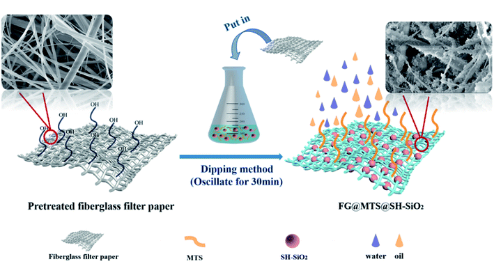
According to the flow chart in Fig. 1, the super-hydrophobic fiberglass filter membrane preparation was divided into three steps. The first step (step I) was the cleaning of fiberglass filter membrane. The fiberglass filter membrane (φ = 47 mm) with the aperture of 0.22 μm was cleaned with deionized water and alcohol three times, and then dried in an oven at 60 °C. The second step (step II) was the preparation of super-hydrophobic fiberglass filter membrane by the impregnation method. Firstly, a defined amount of MTS (15 mM) and SH-SiO2 (0.15 g) were added into a conical flask with 30 mL toluene. The mixture was sonicated for 10 min. In order to investigate the effect of loading density of SH-SiO2 on the performance of the membrane, the SH-SiO2 qualities were set to be 0 g, 0.05 g, 0.1 g, 0.15 g, 0.2 g, 0.25 g, 0.3 g. After that, the pretreated FGm was entirely immersed in the dispersed MTS/SH-SiO2/toluene solution and shook (180 rpm) at 25 °C for 20 min. The last step (step III) was drying the super-hydrophobic fiberglass filter membrane. The modified FGm was repeatedly washed three times with toluene. Upon drying in an oven at 60 °C for 120 min, the SH-SiO2@MTS fiberglass filter membranes were obtained, labelled as M0, M1, M2, M3, M4, M5, M6. Detailed composition of different SH-SiO2@MTS fiberglass filter membranes is shown in Table S1,† and the change of contact angle is shown in Fig. S1.†2.3 Preparation of surfactant-stabilized water-in-oil emulsions (labeled as SE)
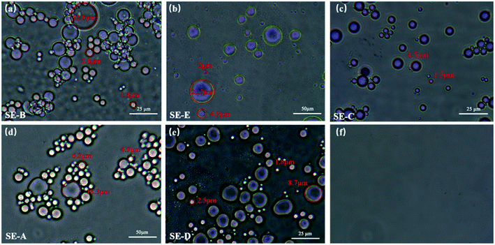
In this work, five types of surfactant-stabilized water-in-oil emulsions were prepared using 2,2,4-trimethylpentane, n-hexane, cyclohexane, petroleum ether and kerosene were named as SE-A, SE-B, SE-C, SE-D, SE-E, respectively. In order to prepare the five types of surfactant-stabilized water-in-oil emulsions, 0.02 g of span-80 was added into cyclohexane (99 mL), n-hexane (99 mL), petroleum ether (99 mL) and 2,2,4-trimethylpentane (99 mL), 0.02 g tween 80 was added into kerosene (99 mL). After the addition of 1 mL water, the mixtures were mechanically sheared for 10 min using a high-speed shearing machine. It can be seen from Fig. 10, the droplet diameters of SE-A, SE-B, SE-C, SE-D, SE-E emulsions are approximately within 0 to 20 μm. The composition and formulation for preparing the five emulsions are shown in Table S2.†2.4 Oil/water separation measurement
The oil–water mixture separation performance of the super-hydrophobic fiberglass filter membrane was evaluated by a device composed of a filter, the prepared membranes and a beaker. The membrane was sandwiched between two glass tubes with a practical inner diameter of 35 mm. 50 mL of the heavy oil (1,2-dichloroethane)–water mixture (1![[thin space (1/6-em)]](https://www.rsc.org/images/entities/char_2009.gif) :
:![[thin space (1/6-em)]](https://www.rsc.org/images/entities/char_2009.gif) 1, v/v, dyed with Sudan III and methylene blue trihydrate, respectively) were added into the upper tube, and the oil spontaneously permeated and flowed into the beaker. The whole process of separating oil and water was driven by gravity.
1, v/v, dyed with Sudan III and methylene blue trihydrate, respectively) were added into the upper tube, and the oil spontaneously permeated and flowed into the beaker. The whole process of separating oil and water was driven by gravity.
2.5 Emulsion separation experiments
The method for testing the separation performance of oil-in-water emulsion is the same as the above method.The separation flux (F) and removal efficiency (R) of SH-SiO2@MTS@FGm was tested by the filter device, which was then calculated by eqn (1) and (2), respectively.
 | (1) |
 | (2) |
2.6 Characterization
The water contact angles of various membranes were examined by contact angle meter (SZ-CAMC11). The surface morphology and elemental map distribution of the membranes were observed by a scanning electron microscope (SEM, JSM7500F, JEOL) with an energy dispersive spectroscopy (EDS). The droplet size distributions of water-in-oil emulsions were tested by electron microscope (LWD300-38LT, Shanghai Tewei Photoelectric Technology Co., Ltd). The water contents (ppm) in water/oil emulsion were determined by trace moisture analyzer (WM-2800). The pH of relevant solutions was tested with pH meter (PHS-3C, Shanghai Precision Scientific Instrument Co., Ltd). The chemical composition of the membrane was characterized by X-ray photoelectron spectroscopy (AXIS Ultra DLD, UK) and Fourier transform infrared spectroscopy (FT-IR, Nicolet 6700).3. Results and discussion
3.1 Preparation of superhydrophobic MTS@SH-SiO2@FGm
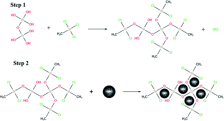
The stable super-hydrophobic/super-oleophilic MTS@SH-SiO2@FGm was developed by a facile method, as shown in Fig. 1. The MTS@SH-SiO2@FGm was fabricated by impregnation method using fiberglass filter membrane as substrate. As shown in Fig. 2a and c, the surface of fiberglass membrane is relatively smooth without any nanoscale features for the pristine fiberglass membrane. Many smooth microfibers with an average diameter at 1 μm mixed together and formed a fibrous network. This is favorable for the silanization of fiberglass, and the uniform deposition of nano fumed silica. As shown in Fig. 2d, after silanization, we have observed that MTS molecules react with the hydroxyl groups on the surface, and aggregate into 3D nanowire arrays atop the fibers. It has been previously proposed that super-hydrophobicity is the result of the polymerized nanostructures (formed by hydrolysis and condensation reactions of MTS) on both glass and silicon surfaces, and this reaction is schematically illustrated in Fig. 3 (step 1). As shown in Fig. 3 (step 2), SH-SiO2 is deposited and cured on the surface of the membrane.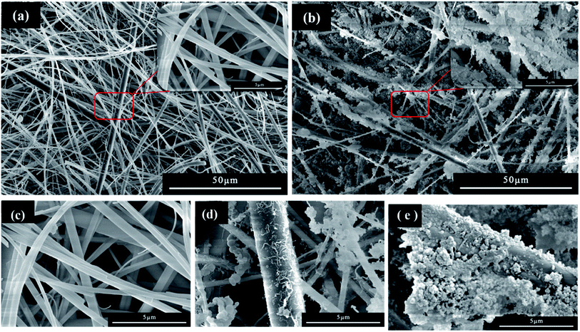 | ||
| Fig. 2 SEM images of (a) and (c) pristine fiberglass membrane, (d) after MTS modified, and (b) and (e) after MTS and SH-SiO2 modified. | ||
As shown in Fig. 2b, with the introduction of nano fumed silica, the roughness of fiberglass membrane is further increased, which promote the improvement of hydrophobicity. As presented in Fig. 2e, numerous nanoscale protrusions reside on the fiberglass, but the primary fiberglass structure is not changed. It also can be seen from Fig. 3 (step 2), due to the molecular force between the MTS and the membrane, the SH-SiO2 is deposited and solidified on the surface of the membrane stably. The presence of nanometer-scale structural features ensures the formation of the Cassie–Baxter state when the nanoscale protrusions are in contact with the water droplets on top.
3.2 Chemical composition of MTS@SH-SiO2@FGm
Chemical compositions of pristine fiberglass membrane and MTS@SH-SiO2@FGm were further investigated through XPS analysis. The high-resolution XPS spectra of the membranes are shown in Fig. 4b. After silanization of MTS and deposition of SH-SiO2, the peaks at 101.25 eV and 103.55 eV are assigned to the Si–C/Si–O, respectively. A new peak attributed to the C–Si group is observed at 101.25 eV, which means MTS has been successfully graft-modified. For the pristine fiberglass membranes, the peaks corresponding to C 1s, O 1s, Si 2s, and Si 2p are shown in Fig. 4a. After silanization by MTS, the Si 2p peak becomes stronger. This means that MTS has been successfully graft-modified and the SH-SiO2 successfully deposited on the surface of the fiberglass membrane. These results indicate that the MTS and SH-SiO2 have a significant effect on the surface chemical composition of FGm. | ||
| Fig. 4 (a) XPS spectra of pristine fiberglass membrane and MTS@SH-SiO2@FGm. (b) Si 2p core-level XPS spectra of MTS@SH-SiO2@FGm. (c) FT-IR spectra of pure fiberglass membrane and MTS@SH-SiO2@FGm. | ||
The interaction between MTS, SH-SiO2 and FGm is also investigated by FT-IR spectra of membranes. As shown in Fig. 4c, the primary characteristic bands of pristine membranes are observed at 790.71 cm−1, 460.92 cm−1, 1039.49 cm−1, which are assigned to the Si–O symmetrical stretching vibration, Si–O bending vibration, Si–O antisymmetric stretching vibration, respectively. Compared with the original fiberglass filter membrane, significant changes have been observed in the spectrum of the MTS@SH-SiO2@FGm. A series of new absorption bands appeared at 698.14 cm−1(Si–Cl stretching vibration), 1265.14 cm−1(Si–C variable angle vibration), 782.99 cm−1(Si–C stretching vibration), 846.64 cm−1 (Si–C stretching vibration), 1407.85 cm−1(–CH3 bending vibration). These absorption bands indicate that MTS is hydrolyzed and condensed with the hydroxyl group on the surface of silicon dioxide. No new absorption bands appear after deposition of SH-SiO2, but the intensity of the absorption band in 790.71 cm−1 (Si–O symmetrical stretching vibration), and 1039.49 cm−1 (Si–O antisymmetric stretching vibration) is enhanced. These results further demonstrate the preparation of MTS@SH-SiO2@FGm successfully.
In addition, EDS mapping of the MTS@SH-SiO2@FGm shows that it is mainly composed of Si, C, O, Cl elements (Fig. S2†). It can be seen from Table 1, after silanization of MTS and deposition of SH-SiO2, the content of Si, C and Cl increases. This is consistent with the XPS depth profiles. As seen from Fig. 5a and b, the contents of C elements become higher. It also can be seen from the Fig. 5c and d, compared with the initial fiberglass filter membrane, the contents of Cl elements increase and distribute over the whole surface. The presence of Cl elements proves that MTS is grafted into the original fiberglass filter membrane. The increase of Si content proves that the SH-SiO2 was successfully deposited on the surface of the FGm.
| C/% | O/% | Si/% | Cl/% | Cl/C | Cl/O | |
|---|---|---|---|---|---|---|
| FGm | 16.17 | 59.54 | 27.01 | 0.00 | 0.000 | 0.000 |
| MTS@SH-SiO2@FGm | 20.41 | 50.21 | 29.18 | 0.21 | 0.010 | 0.004 |
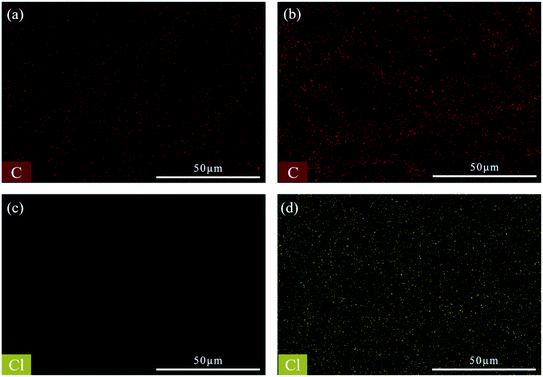 | ||
| Fig. 5 (a) and (c) EDS mappings of initial fiberglass filter membrane. (b) and (d) EDS mappings of modified fiberglass membrane. | ||
3.3 Wetting behaviors of MTS@SH-SiO2@FGm
The different morphologies of the original fiberglass membranes and MTS@SH-SiO2@FGm resulted in different wetting behaviors. As displayed in Fig. 6a, the pristine membrane with high surface energy exhibits super-hydrophilicity, and the water contact angle is 0°, which conformed to Wenzel's wetting theory. After MTS only modified the membrane, it became hydrophobic, and the contact angle was 138.4 ± 0.5° (Fig. 6b). Because the fiberglass filter membrane modified by MTS has low surface energy, compared with the MTS@FGm, the MTS@SH-SiO2@FGm with nano structures are found to exhibit stronger super-hydrophobic with a water contact angle of 156.2 ± 0.5° (Fig. 6c). This phenomenon could be because the SH-SiO2 microparticles further enhanced the roughness of fiberglass filter membrane, so that the surface of fiberglass filter membrane is filled with abundant air layer, preventing water droplets from penetrating the membrane. Hence the two components have a possible synergistic effect to enhance the hydrophobicity of MTS@SH-SiO2@FGm.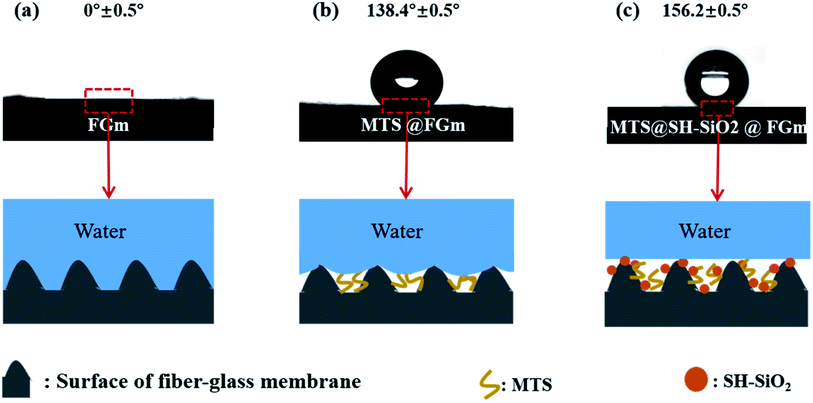 | ||
| Fig. 6 Schematic illustration of surface wetting mechanism of (a) pristine fiberglass membrane, (b) MTS@FGm and (c) MTS@SH-SiO2@FGm. | ||
3.4 Self-cleaning and stability of MTS@SH-SiO2@FGm
The super-hydrophobic properties of the MTS@SH-SiO2@FGm were investigated. As presented in Fig. 7b and Video S1,† the liquid droplets maintain a spherical shape, indicating excellent super-hydrophobic properties and non-wetting behavior of the membrane. Furthermore, when high-speed water comes into contact with the super-hydrophobic surface, a stable layer of air is created to reflect the water flow. Due to air gaps, the water droplets remain approximately spherical shape on the membrane surface. Then, the physical self-cleaning properties of the MTS@SH-SiO2@FGm has been studied by contaminating the membrane surface with dust. As presented in Fig. 7a and Video S2,† water droplets roll off and wash away dirt particles due to the low adhesion on the membrane surface. With increased water dumping, the membrane surface is cleaned to a greater degree, demonstrating excellent self-cleaning performance. These characteristics are significant in many practical applications, such as separating oil and water mixtures containing dust.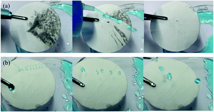 | ||
| Fig. 7 (a) Photographs of water flowing on the membrane surface with dust (b) impact processes of MTS@SH-SiO2@FGm surfaces by water. | ||
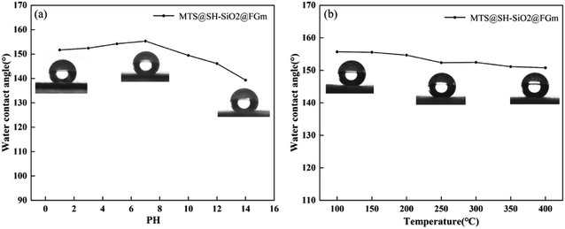
Another critical parameter of the membrane for practical oil–water separations is the chemical stability, as the super-hydrophobic surface could be easily destroyed under a severe corrosive solution and high temperature. Therefore, several extreme circumstances were simulated to evaluate the stability of MTS@SH-SiO2@FGm. The corrosion resistance of the membrane was tested by the 3 μL HCl (pH = 1), NaOH (pH = 14) and NaCl (wt% = 20%) solution. As shown in Fig. S3,† the membrane was not wetted by various water droplets (pure water, HCl, NaOH and NaCl solution), which was demonstrated by the perfect spherical shape on the membrane surface. To further investigate the effect of pH on the super-hydrophobic stability, the MTS@SH-SiO2@FGm was immersed into corrosion solutions with different pH values (1, 3, 5, 7, 10, 12 and 14) for 24 h. In neutral aqueous solution (pH = 7.0), the MTS@SH-SiO2@FGm demonstrated the highest water contact angle (155.32 ± 0.5°). The water contact angle of the membrane in acidic solution (151.69 ± 0.5°) is more significant than that in alkaline solution (139.33 ± 0.5°). These prove that the modified membrane is more hydrophobic in acidic solution than in alkaline solution and can resist the acid environment (Fig. 8a). The modified membrane was placed into a muffle furnace at a different temperature ranging from 0 to 400 °C for 2 h. It is found from Fig. 8b that even under extreme conditions of high temperature, the measured water contact angle is determined to be 150.78 ± 0.5°. These results prove that the MTS@SH-SiO2@FGm can maintain excellent stability even under complex conditions. This is mainly due to the extreme acid corrosive resistance and high thermal stability of SH-SiO2 microparticles and initial fiberglass filter membrane. This means that the membrane can handle acidic mixtures of oil and water, and high-temperature mixtures. Therefore, the superior stability of MTS@SH-SiO2@FGm materials is essential for practical applications.
3.5 Oil/water separation performance of MTS@SH-SiO2@FGm
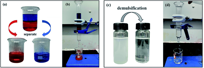
The selective wettability, significant chemical and thermal stability of the membrane (MTS@SiO2@FGm) enable the membrane to separate oil–water mixture efficiently. Hence, an experiment was conducted to assess the properties of the super-hydrophobic/super-oleophilic for oil–water mixture separation. As shown in Fig. 9b and Video S3,† the fiberglass filter membranes were fixed between two glass tubes during the separation process. Subsequently, 20 mL oil–water mixture was slowly added into the upper tube, and the whole separation process was only driven by gravity. During the separation process, the Sudan III-dyed 1,2-dichloroethane droplets into the beaker due to the gravity, while the methylene blue trihydrate-dyed water was repelled and remained in the upper tube. As seen from Fig. 9a, there are no visible water droplets in the collected oil. As expected, all the mixtures are successfully separated in one step. This result demonstrates the separation performance of the MTS@SH-SiO2@FGm for the oil–water mixture.3.6 Water-in-oil emulsions separation performance, and reusability of MTS@SH-SiO2@FGm
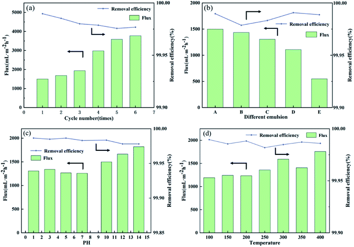
Modified membranes exhibit broad application for water-in-oil emulsions separation based on excellent super-hydrophobic/super-oleophilic properties and oil–water separation capacity. As shown in Fig. 10, to verify the separation performance of MTS@SH-SiO2@FGm, five surfactant-stabilized water-in-oil emulsions with droplets sizes of micro-meters (SE-A, SE-B, SE-C, SE-D and SE-E) were prepared. Typically, the surfactant-stabilized water-in-oil emulsion is kept stable for a week (Fig. 9c). As shown in Fig. 9d and Video S4,† the fiberglass filter membranes were fixed between two glass tubes during the separation process. Subsequently, 10 mL surfactant-stabilized water-in-oil emulsion was slowly added into the upper tube, and the whole separation process was only driven by gravity. Owing to the excellent super-hydrophobic/super-oleophilic properties of membrane, the prepared emulsion can penetrate the membrane immediately as soon as it contacts the surface of the modified membrane. It could be seen from Fig. 9c; the turbid emulsion is transformed into a clear solution after penetrating the membrane. Fig. 10f shows the optical microscope images of sample SE-A after separation, indicating that the MTS@SH-SiO2@FGm effectively separates water-in-isooctane emulsion. Further illustrated from Fig. 11b that the removal efficiencies of all the emulsions tested by the water content tester are above 99.95%, indicating the modified membrane's high separation efficiency (Table S3†). MTS@SH-SiO2@FGm has high removal efficiency for water-in-oil emulsion separation, exhibiting great advantage for oil treatment. It also proves that grafted hydrophobic chain and SH-SiO2 microparticles deposition provide a unique and competitive method to obtain super-hydrophobic membrane with high separation performance.The reusability performance is a key index of separation membrane. For this purpose, 6 cycles of membrane for SE-A were performed, as shown in Fig. 11a. After each cycle, the surface of membrane was washed with absolute ethanol and then dried in an oven for the next cycle. As seen from Fig. 11a, the separation flux is small at the beginning of the cycle experiments. Because the modification agent is heavily deposited onto the membrane and this would lead to the blocking effect during the filtration. At the same time, the removal efficiency decreases with increasing number of cycles, but no sharp drop is observed. Typically, the removal efficiency still reaches above 99.95% and the concentration of water in the collected oil (Cf) is 165.033 mg L−1 after 6 cycles (Table S4†). The stable separation performance is due to the interconnected porous structure of membrane which can effectively block water droplets during the process of oil and water separation. Therefore, MTS@SH-SiO2@FGm exhibits excellent reusability and plays an important role in the practical application of water-in-oil emulsion separation.
In most current studies, the tolerance of super-hydrophobic surfaces is poor due to chemical corrosion and extremely high temperatures. Therefore, the tolerance of MTS@SH-SiO2@FGm in extreme environments is essential for practical applications. Fig. 11d shows the tolerance of MTS@SH-SiO2@FGm in different high-temperature conditions. As seen in Fig. 8b, after treatments for 2 h in high temperature conditions, the water contact angle of membranes is still above 150°, indicating the stability of the super-hydrophobic property. Furthermore, the separation flux of membrane for SE-A emulsion is almost unchanged (about 1500 mL m−2 h−1), the removal efficiency is above 99.95%, and the concentration of water in the collected oil (Cf) is about 100 mg L−1 (Table S5†), which exhibits the excellent tolerance of high-temperature. Then, the chemical tolerance is investigated by immersing the membrane in acid and alkali solution. As shown in Fig. 11c, after immersing the membrane in HCl solution (pH = 1) for 24 h, the membrane could separate SE-A, the separation flux is 1305.939 mL m−2 h−1, the removal efficiency is above 99.95%, and the concentration of water in the collected oil (Cf) is 95.869 mg L−1 (Table S6†). Therefore, based on the above results, the MTS@SH-SiO2@FGm exhibits excellent tolerance in separation properties under high temperature and acidic corrosion conditions. On the one hand, this is mainly attributed to the inherent high temperature resistance and chemical tolerance of fiberglass membranes. On the other hand, the unique chemical structure (including Si–C bond and O–Si–O bond) endows the MTS@SH-SiO2@FGm with high-temperature resistance and good acidic corrosion resistance. Compared with other inorganic metal oxides materials, it is expected that these features would make the MTS@SH-SiO2@FGm more applicable under extreme conditions.
4. Conclusions
In summary, the impregnation method successfully prepared a fiberglass filter membrane with the structure of 3D nanowire arrays and nanoscale protrusions. The membrane has super-hydrophobic/super-oleophilic, self-cleaning, stability, reusability, oil/water separation, and micron-scale water-in-oil emulsions separation performance. As a result, the resulting membranes exhibit high removal effectivity (up to 99.98%) for surfactant-stabilized water-in-oil emulsions under gravity drive. Besides, the resulting membranes remain high separation efficiency after 6 cycles (removal efficiency > 99.95%, the concentration of water in the collected oil: 165.033 mg L−1). Moreover, the MTS@SH-SiO2@FGm could separate micro-scale water-in-oil emulsions stably in extreme conditions, including strongly acidic corrosive solutions, and high-temperature systems. Therefore, in the field of separating water-in-oil emulsions under harsh conditions, the super-hydrophobic/super-oleophilic MTS@SH-SiO2@FGm has potential advantages.Conflicts of interest
There are no conflicts to declare.Acknowledgements
We gratefully acknowledge financial support from the National Natural Science Foundation of China (21776181), Sichuan University Innovation Spark project (2018SCUH0012), Chinese National Key Research and Development Plan (2018YFC1900203-03), and Science and Technology Plan Project of Sichuan Province (2021YFG0285).References
- Y. Xiao, W. Huang, C. P. Tsui, G. Wang, C. Y. Tang and L. Zhong, Composites, Part B, 2017, 121, 92–98 CrossRef CAS.
- S. He, Y. Zhan, Y. Bai, J. Hu, Y. Li, G. Zhang and S. Zhao, Composites, Part B, 2019, 177, 107439 CrossRef CAS.
- C. Teodosiu, A. F. Gilca, G. Barjoveanu and S. Fiore, J. Cleaner Prod., 2018, 197, 1210–1221 CrossRef CAS.
- K. Wang, T. C. Zhang, B. Wei, S. Chen, Y. Liang and S. Yuan, Colloids Surf., A, 2021, 608, 125342 CrossRef CAS.
- M. Sajid, M. K. Nazal, Ihsanullah, N. Baig and A. M. Osman, Sep. Purif. Technol., 2018, 191, 400–423 CrossRef CAS.
- J. C. Paton and A. W. Paton, Microb. Pathog., 1996, 20, 377–383 CrossRef CAS PubMed.
- M. J. Bashir, J. H. Lim, S. S. Abu Amr, L. P. Wong and Y. L. Sim, J. Cleaner Prod., 2019, 208, 716–727 CrossRef CAS.
- D. Ge, L. Yang, C. Wang, E. Lee, Y. Zhang and S. Yang, Chem. Commun., 2015, 51, 6149–6152 RSC.
- H. Kang, X. Zhang, L. Li, B. Zhao, F. Ma and J. Zhang, J. Colloid Interface Sci., 2020, 559, 178–185 CrossRef CAS PubMed.
- Z. Zhang, P. Mu, J. He, Z. Zhu, H. Sun, H. Wei, W. Liang and A. Li, ChemSusChem, 2019, 12, 426–433 CrossRef CAS PubMed.
- X. Lin, M. Choi, J. Heo, H. Jeong, S. Park and J. Hong, ACS Sustainable Chem. Eng., 2017, 5, 3448–3455 CrossRef CAS.
- Y. Cao, Y. Chen, N. Liu, X. Lin, L. Feng and Y. Wei, J. Mater. Chem. A, 2014, 2, 20439–20443 RSC.
- C. F. Wang and S. J. Lin, ACS Appl. Mater. Interfaces, 2013, 5, 8861–8864 CrossRef CAS PubMed.
- Z. Wang, C. Xiao, Z. Wu, Y. Wang, X. Du, W. Kong, D. Pan, G. Guan and X. Hao, J. Mater. Chem. A, 2017, 5, 5895–5904 RSC.
- R. Gao, X. Liu, T. C. Zhang, L. Ouyang, Y. Liang and S. Yuan, Ind. Eng. Chem. Res., 2020, 59, 21510–21521 CrossRef CAS.
- S. Zhang, F. Lu, L. Tao, N. Liu, C. Gao, L. Feng and Y. Wei, ACS Appl. Mater. Interfaces, 2013, 5, 11971–11976 CrossRef CAS PubMed.
- Z. Liu, W. Wu, Y. Liu, C. Qin, M. Meng, Y. Jiang, J. Qiu and J. Peng, Sep. Purif. Technol., 2018, 199, 37–46 CrossRef CAS.
- H. He, Z. Li, L. Ouyang, Y. Liang and S. Yuan, J. Alloys Compd., 2021, 855, 157421 CrossRef CAS.
- C. H. Kung, B. Zahiri, P. K. Sow and W. Mérida, Appl. Surf. Sci., 2018, 444, 15–27 CrossRef CAS.
- Y. Liao, C. H. Loh, M. Tian, R. Wang and A. G. Fane, Prog. Polym. Sci., 2018, 77, 69–94 CrossRef CAS.
- X. Bai, Y. Shen, H. Tian, Y. Yang, H. Feng and J. Li, Sep. Purif. Technol., 2019, 210, 402–408 CrossRef CAS.
- S. M. Kale, P. M. Kirange, T. V. Kale, N. Jee Kanu, E. Gupta, S. S. Chavan, U. Kumar Vates and G. Kumar Singh, Mater. Today: Proc., 2021, 47, 3186–3189 CAS.
- G. Zhai, L. Qi, W. He, J. Dai, Y. Xu, Y. Zheng, J. Huang and D. Sun, Environ. Pollut., 2021, 269, 116118 CrossRef CAS PubMed.
- J. Xie, J. Hu, L. Fang, X. Liao, R. Du, F. Wu and L. Wu, Surf. Coat. Technol., 2020, 384, 125223 CrossRef CAS.
- Y. Zhang, Y. Zhang, Q. Cao, C. Wang, C. Yang, Y. Li and J. Zhou, Sci. Total Environ., 2020, 706, 135807 CrossRef CAS PubMed.
- J. Li, R. Kang, X. Tang, H. She, Y. Yang and F. Zha, Nanoscale, 2016, 8, 7638–7645 RSC.
- G. C. Bandara, C. A. Heist and V. T. Remcho, Talanta, 2018, 176, 589–594 CrossRef CAS PubMed.
- M. I. Siyal, A. A. Khan, C. K. Lee and J. O. Kim, Sep. Purif. Technol., 2018, 205, 284–292 CrossRef CAS.
- X. Yin, C. Sun, B. Zhang, Y. Song, N. Wang, L. Zhu and B. Zhu, Chem. Eng. J., 2017, 330, 202–212 CrossRef CAS.
- S. Movafaghi, M. D. Cackovic, W. Wang, H. Vahabi, A. Pendurthi, C. S. Henry and A. K. Kota, Adv. Mater. Interfaces, 2019, 6, 1–6 Search PubMed.
Footnote |
| † Electronic supplementary information (ESI) available. See DOI: 10.1039/d1ra08841f |
| This journal is © The Royal Society of Chemistry 2022 |

