 Open Access Article
Triboelectrochemical friction control of W- and Ag-doped DLC coatings in water–glycol with ionic liquids as lubricant additives
Hamid Khanmohammadi *a,
Wahyu Wijanarko
 ab,
Sandra Cruz
 cd,
Manuel Evaristod and
Nuria Espallargas
 a
a
aNorwegian Tribology Center, Department of Mechanical and Industrial Engineering, Norwegian University of Science and Technology (NTNU), Trondheim, Norway. E-mail: hamid.khanmohammadi@ntnu.no
bDepartment of Mechanical Engineering, Sepuluh Nopember Institute of Technology (ITS), Surabaya, Indonesia
cIPN – LED & Mat – Instituto Pedro Nunes, Laboratory of Tests, Wear and Materials, Rua Pedro Nunes, Coimbra, 3030-199, Portugal
dCEMMPRE Mechanical Engineering Department, University of Coimbra, 3030-788 Coimbra, Portugal
First published on 27th January 2022
Abstract
In the last years, diamond like carbon (DLC) coatings doped with both carbide forming and non-carbide forming metallic elements have attracted great interest as novel self-lubricating coatings. Due to the inherent properties of DLC, the doping process can provide adsorption sites for lubricant additives depending on the chemical and electrochemical state of the surface. Ionic liquids (ILs) are potential lubricant additives with good thermal stability, non-flammability, high polarity, and negligible volatility. These characteristics make them also ideal for polar fluids, like water-based lubricants. In this work, three different DLC coatings (DLC, W- and Ag-doped DLC) were deposited on stainless steel substrates and their friction in dry and lubricated conditions in water-based lubricants was studied. Three ILs, tributylmethylphosphonium dimethylphosphate (PP), 1,3-dimethylimidazolium dimethylphosphate (IM) and 1-butyl-1-methylpyrrolidinium tris(pentafluoroethyl)trifluorophosphate (BMP) were used as additives and compared with a well-known organic friction modifier (dodecanoic acid). The results showed better mechanical integrity, toughness and adhesion of the doped coatings compared to the undoped DLC. The Ag-doped DLC coating had the best mechanical properties of all the coatings. W formed tungsten carbide precipitates in the DLC coating. Two different additive-adsorption mechanisms controlled friction: a triboelectrochemical activation mechanism for Ag-DLC, and an electron-transfer mechanism for W-DLC resulting in the largest reduction in friction.
1. Introduction
Growing concerns and considerations regarding energy management and environmental sustainability push different industries to look thoroughly into how industrial activities can be conducted more efficiently and cleanly. Friction consumes about 23% of all energy use worldwide.1 Moreover, the amount of CO2 emissions due to friction and wear is calculated as 8120 million tons per year by a simple assumption of a direct relationship between energy use and emissions.2 The above-mentioned facts indicate that friction and wear have a huge share in the total energy consumption and environmental pollution worldwide. Different types of transportation vehicles consume about 30% of the daily energy production and about one third of it dissipates due to friction and wear. Therefore, about 10% of global energy is due to loss via tribological contacts in vehicles.2,3Switching from conventional internal combustion engine (ICE) vehicles to electric vehicles (EV) is a great breakthrough towards higher energy efficiency and a greener environment.4 In a typical ICE passenger car about 21% of the fuel consumption is being used to move the car while in an EV this ratio is about four times higher (77%).3 One of the main challenges in further development of EVs is the need for new lubricating solutions dedicated only to them. The higher torque in EVs can cause more severe wear issues than in conventional ICE vehicles.5 This shows the urgent need for new, more efficient, and greener frictional and anti-wear lubricating solutions, both as base lubricants and additives. Moreover, studies have shown that adjusting the viscosity of lubricants can be beneficial, Gupta reported that the use of a low-viscosity oil instead of a conventional high-viscosity oil can lead to about 17% higher engine efficiency in EVs.6 However, the use of low viscosity lubricants will result in thinner fluid film thicknesses and asperity contact of the surfaces in relative motion is to be expected. Therefore, the use of coatings in moving components becomes a need. Thus, any effective measure to decrease friction and wear in the main energy consuming industries such as transportation, can result in lower CO2 emissions. These measures can be achieved by (a) new lubricating solutions and lubricant additives, (b) new materials, surface treatments and coatings, and (c) advanced component design.7
New lubricating solutions could be achieved by designing new lubricant additives based on the application needs. In addition, multifunctionality of additives can also lead to simpler lubricant formulations that are easier to recycle. Ionic liquids (ILs) have been emerging since the early 2000s as potential base stocks or lubricant additives because of their unique physicochemical properties together with their inherent polarity and good surface adsorption.8–11 ILs are room temperature molten salts consisting of one anionic and one cationic moiety. ILs show some interesting and unique properties such as non-flammability, low vapour pressure, ashless behaviour and high thermal stability.12,13
As lubricant additives, two lubricating mechanisms are proposed in literature: (1) formation of adsorbed layers and (2) tribofilm formation on the surface of metals.14 Adsorbed layers on surfaces promote easy to shear behaviour and lead to decrease in friction. The proposed mechanism for the surface adsorption is based on the attraction of the anionic part of ILs to the positively charged surface of metals.14,15 Subsequently, the cationic part of IL can be adsorbed to another anionic moiety and based on the physical properties of anionic and cationic moieties single- or multi-layer adsorbed structures can be formed on the surface resulting in a brush-type adsorbed film on the metal surface. The brush-type, thin and soft adsorbed layers facilitate the relative motion of the contacting surfaces modifying friction. The second mechanism is based on the tribochemical reaction of ILs with the metallic surface and the subsequent formation of a tribofilm.16,17 The in situ formed tribofilm can result in decreased friction and wear. One of the main concerns regarding the use of ILs as lubricant additives is their ionic nature, which can result in corrosion and tribocorrosion of metals.18,19 This problem can be addressed by choosing the materials with the right corrosion properties or by using coatings, such as ceramics or DLCs.
Diamond-like carbon (DLC) coatings are a promising group of coatings for use in rotating parts and low viscosity lubricants. They possess good anti-wear behaviour and high corrosion resistance due to their inert nature.20–22 They have high hardness, and in tribological contacts, they undergo a graphitization process leading to very low friction and reduced wear in boundary lubricating conditions.23,24 Moreover, DLC coatings can act as a physical barrier hindering corrosion and tribocorrosion on the metal surfaces.25–28 However, DLC coatings show high compressive residual stresses and therefore low adhesion to ferrous substrates.29,30 Furthermore, DLC coatings have low surface energy and inert chemical nature, resulting in limited reactivity with lubricant additives.31 Doping DLC coatings with different carbide forming (Ti, W, Cr) elements or non-carbide forming (Ag, Au, Cu) elements has been addressed as a solution to overcome the above-mentioned drawback.31 Incorporation of the doping elements to the structure of DLCs reduces the compressive residual stresses in the coating and leads to better adhesion to the substrate.29,30,32 Furthermore, higher reactivity is expected on the doping sites in the coating's structure, providing with preferential adsorption sites for the lubricant additives facilitating their friction modifying properties on DLC coatings.
This research paper aims to investigate the ability of ionic liquids as friction modifiers in water-based lubricants for metal doped DLC coatings deposited on stainless steel substrates. The effect of the type of metal (carbide and non-carbide forming, i.e. W- and Ag-) on the mechanical and structural behaviour of DLC coatings has been investigated and compared with an undoped DLC coating. The frictional and wear performance of DLC coatings are discussed in both dry and lubricated conditions and the effect of electrical conductivity and electrochemical potential on the activation of the surface adsorption sites, and consequently, on their frictional behaviour has been thoroughly studied.
2. Experimental procedure
2.1. Materials
AISI 316L grade austenitic stainless steel was chosen as the substrate. Test samples were cut from a rod with a diameter of 40 mm in the shape of disks with a thickness of 6 mm. Specimen surfaces were ground to 4000 grit SiC paper followed by polishing using a 3 μm diamond particle containing suspension. The steel disks were coated with undoped DLC, 10WDLC (10 at% tungsten doped) and 10AgDLC (10 at% silver doped) using a process of direct current magnetron sputtering (DCMS). The DCMS parameters were optimized to achieve highly dense coatings with an average thickness of about 3 μm. More details of the DCMS deposition parameters and optimization for coatings' deposition are described elsewhere.31,32The water-based lubricant was prepared by mixing 50–50 weight percent of distilled water and a glycol. Three different ionic liquids, tributylmethylphosphonium dimethylphosphate (PP), 1,3-dimethylimidazolium dimethylphosphate (IM) and 1-butyl-1-methylpyrrolidinium tris(pentafluoroethyl)trifluorophosphate (BMP) were used as additive in the concentration of 1 wt%. The reference lubricant was formulated using the same base fluid and adding 0.1 wt% of dodecanoic acid (C12). This concentration was chosen based on a study performed in our research group in which it was found that 1 wt% was the optimum concentration for ILs in water–glycol media (ILs were tested at different concentrations: 0.25, 0.5, 1, 2, and 4 wt%). 0.1 wt% is the optimal concentration for C12 in water–glycol lubricant to avoid micelle formation.33 The chemical formula, ionic structure and molecular weight of the additives are listed in Table 1. The formulated fluids were mixed by a magnet stirrer for 2 hours at 40 °C and the pH and electrical conductivity of the lubricants were measured using a HANNA HI-23 Benchtop conductivity/pH meter. The density of the lubricants was calculated by weighing a constant volume of the fluids. The dynamic viscosity of the formulated fluids was measured by a Haake Mars Rotational rheometer at 23 °C in humid air. The measurement procedure was as follows: The shear rate was increased from 0.01 to 500 s−1, held at a constant shear rate of 500 s−1 for 30 s and then decreased to the initial value. The mentioned cycle was repeated twice for each fluid. The viscosity number at the fixed shear rate was measured each second and the average of 60 measurements (during the two cycles) is reported. The electric conductivity, pH, viscosity, and density of the formulated lubricants are presented in Table 2.
| Lubricant | wt% of additive | pH | Conductivity (μS cm−1) | Viscosity (mPa s) | Density (g cm−3) |
|---|---|---|---|---|---|
| WG | — | 7.3 | 2.5 | 13.3 | 1.040 |
| WG-IM | 1 | 7.1 | 401.1 | 13.1 | 1.044 |
| WG-PP | 1 | 3.4 | 211.2 | 13.0 | 1.039 |
| WG-BMP | 1 | 7.0 | 109.3 | 13.3 | 1.045 |
| WG-C12 | 0.1 | 4.7 | 4.3 | 13.3 | 1.041 |
2.2. Testing and characterization methods
Coating hardness was evaluated by nanoindentation using a Micro Materials nanotest platform. To avoid any effect of the substrate and Cr interlayer, a 10 mN load was used and the maximum depth was about 200 nm. The adhesion of the coatings was tested by a conventional scratch test with a diamond tip, with a radius of 200 μm. The maximum load used for the scratch tests was 50 N. The critical loads were determined by the observation of the scratches with an optical microscope.The surface chemistry of different coatings was studied by X-ray photoelectron spectroscopy (XPS) using a Kratos Axis Ultra DLD. A monochromatic Al-Kα source with the current of 10 mA and voltage of 10 kV was used to perform the tests. The XPS sample chamber pressure was 1 × 10⁻⁹ Torr during the acquisitions. Depth profile studies were performed using ion milling by Argon sputtering at the Argon pressure of 6.9 × 10⁻⁷ Torr and energy of 4 keV. Three different sets of acquisition were made after 0, 5 and 35 s of ion sputtering. CasaXPS software was used to analyse the XPS data and fit the curves.
The electrochemical behaviour of the samples was evaluated by means of potentiodynamic polarization measurements in the base fluid and the formulated lubricants. The cathodic and anodic curves were scanned separately by a Gamry Reference 600+ potentiostat/galvanostat using a three-electrode setup consisting of Pt wire as counter electrode, Ag/AgCl/KClsat as reference and the DLC coated discs as working electrode. After the stabilization of the open circuit potential (OCP), the cathodic branches were scanned from OCP to −500 mV vs. OCP and the anodic branches were scanned from OCP up to 500 mV vs. OCP at a scan rate of 0.1 mV s−1.
The tribological and tribocorrosion behaviour of the coatings in different formulated lubricants was evaluated using a reciprocating pin-on-disc tribometer (TE 38-Phoenix Tribology) equipped with a three-electrode tribocorrosion cell. The tests were performed with a stroke length of 10 mm at room temperature with the frequency of 1 Hz. An alumina ball with a diameter of 6 mm was used as counterpart and the normal load was 20 N. The OCP tribocorrosion tests consisted of three steps: (1) stabilization of the potential for 10 min; (2) rubbing under the open circuit potential for 2500 seconds; (3) recovery period at open circuit potential for 15 min. For some of the formulated lubricants, potentiostatic and potentiodynamic tribocorrosion tests were performed. In the case of potentiostatic tribocorrosion tests, the working electrode (the coating) was polarized to a certain potential and kept at that potential during the rubbing period. For the potentiodynamic tests, the samples were polarized at the measured OCP during the first 500 s of rubbing and after that the potentiostat/galvanostat started to apply anodic potentiodynamic potential with the scan rate of 0.1 mV s−1 up to 450 mV above the measured OCP. During all the mentioned tribocorrosion tests, the coefficient of friction (CoF) was measured using an x-axis load sensor. At least two tests were performed to check the repeatability of the results. After the tribocorrosion tests, the wear track morphology was examined by a scanning electron microscope (FEI Quanta 650 FEG).
3. Results
3.1. Characterization of the DLC coatings
Fig. 1 shows the typical load-displacement curves for 15 different indentations on each of the coatings and the average hardness and elastic modulus derived from the nanoindentation curves. The undoped DLC coating had the highest hardness and elastic modulus. By introducing tungsten to the coatings, both the hardness and the elastic modulus show a decrease. In the case of 10AgDLC, hardness is slightly higher than the W-doped coating, but the elastic modulus is the lowest of all coatings. The detailed results of hardness and elastic modulus of the coatings are presented in Table 3.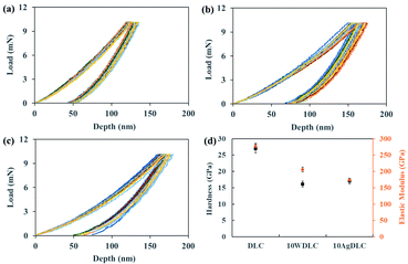 | ||
| Fig. 1 Load-displacement curves of several indentations on (a) DLC, (b) 10WDLC, (c) 10AgDLC and the average hardness and elastic modulus of the coatings (d). | ||
| Coating | Hardness (GPa) | Elastic modulus (GPa) | H/E | H3/E2 |
|---|---|---|---|---|
| DLC | 27.0 ± 1.3 | 276.8 ± 9.1 | 0.0975 | 0.257 |
| 10WDLC | 16.1 ± 0.9 | 206.0 ± 7.2 | 0.0782 | 0.098 |
| 10AgDLC | 17.1 ± 0.9 | 174.0 ± 4.9 | 0.0983 | 0.165 |
It is known that surfaces with higher hardness can resist abrasive wear better. Moreover, elastic deformation occurs easily in materials with lower elastic modulus. Thus, the ratio of hardness to elastic modulus (H/E) and the plastic deformation resistance factor (H3/E2) are helpful factors to describe the mechanical behaviour of the coatings.29,34 The H/E and H3/E2 ratios for the coatings extracted for the nanoindentation results are shown in Table 3. The 10AgDLC coating shows the highest H/E ratio followed by DLC, and 10WDLC. This factor can highlight the benefit of a low elastic modulus together with relatively high hardness. The undoped DLC coating has the highest resistance against plastic deformation (H3/E2) followed by 10AgDLC, and 10WDLC. As it can be seen in the H3/E2 factor, higher hardness is more important than elastic modulus to provide higher resistance against plastic deformation. Therefore, the undoped DLC coating shows the highest plastic deformation resistance factor, while the 10AgDLC has the highest hardness to modulus ratio.
The effect of tungsten doping on the mechanical properties of the DLC coatings were in good agreement with previous studies.29,31,35 Yue et al. have shown that by doping tungsten to the structure of DLC coatings up to about 3 at% the hardness decreases, but by further increase in W-content both elastic modulus and hardness increase.35 They have proposed the competition between sp3/sp2 and tungsten carbide (WC) content in the structure as the main factor determining the mechanical behaviour of the coatings: W-doping results in reduction in sp3/sp2 ratio but increase in the formation of WC phase in the structure. Cao et al. have suggested that ultralow concentration of W (up to maximum 1 at%) is able to enhance hardness, the hardness to elastic modulus ratio (H/E) and the plastic deformation resistance factor (H3/E2).29 At higher W-contents (up to about 15 at% in their study), because of breakage of C–C bonds to form W–C, hardness is decreased. In this work, at a 10 at% of W the effect of WC phase became dominant leading to a decrease in hardness.
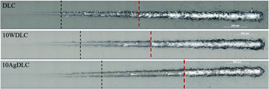
Fig. 2 illustrates the scratch morphology of the coatings. The critical scratch loads of LC1 and LC2 are shown on the images by black and red lines, respectively. LC1 is associated with the start of cracking in the coatings and indicating the cohesive failure in the coatings, while LC2 is associated with the chipping failure, removal of the coatings and indicating adhesive failure between the coating and the substrate.36
The poor adhesion behaviour of undoped DLC coating is attributed to the high compressive residual stress in the structure.32,37 Metal doping of DLC coatings is reported to reduce the compressive residual stress level in the structure resulting in a better adhesion to the substrate compared to undoped DLC coatings.37,38 The poor adhesion of undoped DLC improved by adding 10 at% W. Wang et al. showed that the W–C bond length is longer than the C–C bond length and at higher W concentrations this can overcome the beneficial effect of W on the residual stress resulting in an increment of the compressive stress in the coating structure.39 10AgDLC shows the best adhesion behaviour among all coatings investigated in this study. It has been shown in the literature that incorporation of noble metals such as Ag into the structure of DLC coatings results in a ductile and soft nano-scale phase leading to improved adhesion and toughness.32 The amount of residual compressive stress in DLC coating's structure can be reduced by 5% and 55% by incorporation of 0.6 at% and 3.4 at% Ag to the coating, respectively.40
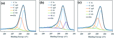
The atomic concentration of W and Ag derived from the survey XPS spectra after 35 s sputtering of 10WDLC and 10AgDLC were 9.6 and 9.0%, respectively. Fig. 3 illustrates the XPS spectrum of C 1s peak of the DLC coatings. The quantitative distribution of different chemical bonds derived from the peaks illustrated in Fig. 3 are presented in Table 4.
| Coating | sp2 (%) | sp3 (%) | sp3/sp2 | C–O (%) | C![[double bond, length as m-dash]](https://www.rsc.org/images/entities/char_e001.gif) O (%) O (%) |
C–W (%) |
|---|---|---|---|---|---|---|
| DLC | 53.4 | 36.6 | 0.69 | 7.6 | 2.4 | — |
| 10WDLC | 51.1 | 18.9 | 0.37 | 9.8 | 2.2 | 18.0 |
| 10AgDLC | 54.2 | 32.1 | 0.60 | 10.4 | 3.3 | — |
The C 1s XPS spectra of the undoped DLC coating consists of four peaks of C–sp2, C–sp3, C–O and C![[double bond, length as m-dash]](https://www.rsc.org/images/entities/char_e001.gif) O and shows the highest sp3/sp2 (0.69) ratio. This is in good agreement with its highest hardness and elastic modulus and its poor adhesion behaviour due to high residual stress in the structure. By incorporating tungsten to the structure of the DLC coatings, C–W peak appears in the C 1s spectra of 10WDLC by an atomic concentration of 18% and the sp3/sp2 ratio decreases to 0.37. As it was mentioned before, the mechanical behaviour of W-doped DLC coatings is determined by considering the competition between decreased sp3/sp2 ratio and increased WC-content.
O and shows the highest sp3/sp2 (0.69) ratio. This is in good agreement with its highest hardness and elastic modulus and its poor adhesion behaviour due to high residual stress in the structure. By incorporating tungsten to the structure of the DLC coatings, C–W peak appears in the C 1s spectra of 10WDLC by an atomic concentration of 18% and the sp3/sp2 ratio decreases to 0.37. As it was mentioned before, the mechanical behaviour of W-doped DLC coatings is determined by considering the competition between decreased sp3/sp2 ratio and increased WC-content.
Based on the XPS, nanoindentation and scratch results, adding 10 at% W to the structure of undoped DLC coating resulted in a reduction of hardness and elastic modulus and better adhesion to the substrate. The XPS spectra of 10AgDLC shows higher amount of C-sp3 phase and higher sp3/sp2 ratio (0.60) compared to the W-doped coating. This can be the reason for having a slightly higher hardness than the W-doped coating. The elastic modulus of 10AgDLC is the lowest among the studied coatings because of the dampening effect of the soft Ag phase in the DLC matrix. Furthermore, the Ag-doped coating shows the best adhesion to the substrate due to the low internal stress.
3.2. Tribocorrosion behaviour at open circuit potential of the DLC coatings
Fig. 4 illustrates the evolution of the open circuit potential (OCP) during the tribocorrosion tests in the water–glycol base lubricant and the additivated water–glycol lubricants. The potential drop of the coatings was lower in WG and WGC12 compared to the IL-containing water-based lubricants. This is due to the lower electrical conductivity of the base fluid (WG) and WGC12 compared to the lubricants formulated with ILs (Table 2). The lack of electrical conductivity results in high ohmic drop between the working electrode (DLC coatings) and the reference electrode. The ionic nature of the ILs together with the high polarity of the base components lead to two orders of magnitude higher electrical conductivity of WGIM, WGPP and WGBMP compared to WG and WGC12.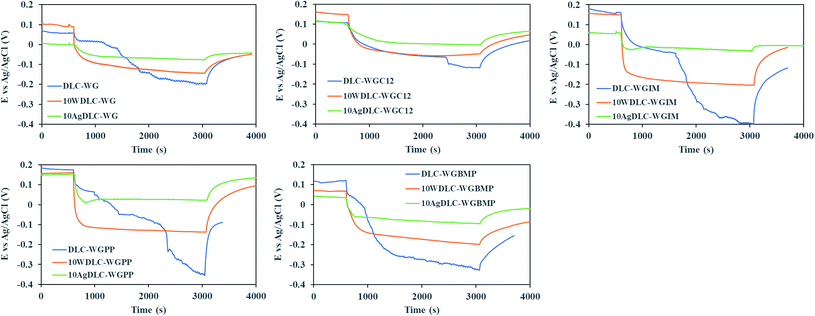 | ||
| Fig. 4 Open circuit potential (OCP) evolution during the tribocorrosion tests of the DLC coatings in water–glycol base lubricant and the additivated lubricants. | ||
In the case of undoped DLC, two or three different electrode potential regions are seen during rubbing: At the on-set of rubbing, a gradual drop in potential happens and this initial drop depends on the electrical conductivity of the lubricant. This initial phase continues until another sudden drop happens, which corresponds to the onset of coating detachment from the substrate. The second sudden drop in the OCP of undoped DLC is related to the lack of mechanical integrity and partial or total removal of the coating from the substrate.
Fig. 5 shows examples of typical defects found on the surface of the wear track of the undoped, W-doped and Ag-doped after the tribocorrosion tests. These defects result in the exposure of the substrate (316L stainless steel) to the solution leading to a more anodic situation inside the wear track and a larger cathodic potential drop, which is typical of passive metal alloys.41 The metal doped DLC coatings had better mechanical integrity than the undoped DLC. However, 10WDLC showed larger OCP drop than 10AgDLC in all the lubricants. Indeed, more, and bigger defects are found in the wear tracks of 10WDLC which exposes a larger area of the substrate to the lubricant (Fig. 5), leading to a more anodic condition in the wear track. This can be due to the dominant effect of the WC phase (i.e. higher hardness and lower adhesion). The presence of Ag-rich islands dispersed in the structure of the DLC matrix results in the best combination of hardness and toughness together with superior adhesive behaviour of 10AgDLC leading to a better mechanical integrity during the rubbing process. Smaller and less defects are found in the wear tracks of 10AgDLC (Fig. 5).
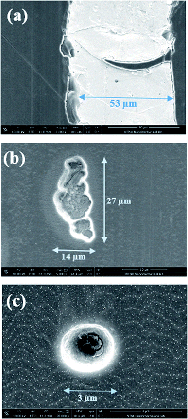 | ||
| Fig. 5 SEM images of the defects found on the wear tracks of the undoped DLC (a), 10WDLC (b) and 10AgDLC (c) after the tribocorrosion tests in WGIM. | ||
3.3. Frictional behaviour in dry and lubricated conditions at OCP
Fig. 6 illustrates the evolution of coefficient of friction (CoF) of the alumina ball sliding against the DLC coatings in dry and lubricated conditions.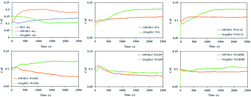 | ||
| Fig. 6 The evolution of coefficient of friction (CoF) during the tribological tests in dry and lubricated conditions. | ||
The undoped DLC coatings in lubricated conditions are not included because the coatings lost their mechanical integrity in all tests. In dry conditions, friction stabilizes after about 1300 seconds of rubbing. 10AgDLC showed the lowest friction followed by undoped DLC and 10WDLC. The CoF graphs of the coatings in WG and WGC12 are almost same revealing no effective function of the carboxylic acid as a friction modifier. Interestingly, in all lubricated conditions, 10AgDLC showed the highest friction as opposite to the dry conditions. The lowest friction in lubricated conditions was for 10WDLC. For 10WDLC, the lowest friction was achieved in WGIM and for 10AgDLC it was in WGPP.
4. Discussion
4.1. Adsorption and frictional behaviour on the W-doped coating: electron-transfer control
DLC coatings are mainly composed of diamond-type sp3 bonds and graphite-type sp2 bonds. The investigations have shown that the steady-state low coefficient of friction in DLC coatings is due to wear induced graphitization and the local formation of a low friction graphite tribolayer in the contact area.42 Different mechanisms are proposed for this process, such as shear deformation that converts (111)DLC into (002)GR graphite planes facilitating nucleation of graphite inside the contact area.43 Molecular dynamics simulations have shown an increase in sp2 content and a decrease in sp3 content on the surface after passing the running in period and reaching the steady state friction.44 Higher contact pressures result in more severe flash temperatures in the contact region facilitating graphitization.45 Tungsten is a carbide forming element when used as dopant in DLCs. Tungsten carbide as a hard phase in the structure of DLCs can bear part of the contact pressure and interrupt the graphitization in the contact region. This might be the reason for higher friction of 10WDLC compared to undoped DLC in dry conditions.In lubricated conditions, the friction of undoped DLC and W-doped DLC is influenced by the surface electrical charge and the ability of the lubricant additives to adsorb to the surface. Despite the rather low electrical resistivity of WC (0.2 μΩ cm−1), the presence of WC islands in the structure of DLC is not expected to have an effect on the surface electrical charge because WC is a ceramic material with a hexagonal structure of W atoms are trapped between C layers. In this case, the electrical conductivity of the lubricant will be the driving force for the transport of additives to the surface.
Table 5 shows the average friction along with the electrical conductivity of the lubricants for different testing conditions of the W-doped DLC after friction stabilization. The friction numbers are shown in three decimals and the standard deviation for all tests after stabilization was about 0.001.
| Dry | WG | WGC12 | WGIM | WGPP | WGBMP | |
|---|---|---|---|---|---|---|
| CoF | 0.181 | 0.109 | 0.109 | 0.079 | 0.082 | 0.092 |
| Conductivity (μS cm−1) | — | 2.5 | 4.3 | 401.1 | 211.2 | 109.3 |
Interestingly, as Table 5 shows, the friction evolution follows the electrical conductivity of WGIM, WGPP and WGBMP, i.e. the lowest friction is found for WGIM (highest electrical conductivity) and the highest friction is found for WG and WGC12 (lowest electrical conductivity).
M. Jelinek et al. have shown that the Zeta-potential of DLC surfaces in aqueous solutions at pH values above its isoelectric point, have a negative value.46,47 Since the surface is negatively charged, the deprotonated (negatively charged) C12 molecules are repelled from the surface resulting in no change in friction by the addition of C12 to the water–glycol base fluid. In the case of the IL-additivated lubricants, the frictional functionality depends on the formation of the electrical double layer on the coating surface and therefore, the transport kinetics of the cation and anion moieties are faster at higher electrical conductivity. The higher the electrical conductivity of the electrolytes, the faster they will be transported to the electrical double layer formed at the surface of the coating. The adsorption of the additives to the surface will be thus controlled by the electron transfer of the electrolytes on the coating surface, and this process will be faster for the electrolyte with the highest electrical conductivity. Therefore, in this case, the WGIM resulted in the lowest friction of all formulated lubricants due to its higher electrical conductivity.
4.2. Adsorption and frictional behaviour on the Ag-doped coating: triboelectrochemical control
The friction plots in Fig. 6 show that 10AgDLC has the lowest friction in dry conditions, among all coatings. The presence of Ag ductile phase in the DLC matrix facilitates energy absorption during local deformations in the contact zone and results in less coating detachment and better anti-wear properties.32 In addition, Ag is a well-known solid lubricant. It is well understood that silver can diffuse and segregate to the coating surface even at room temperature and this strongly influences the frictional behaviour.48–50 The diffusion process is thermodynamically favoured since the growth of the Ag sites on the surface results in the reduction of surface energy.42 Moreover, high local temperature in the contact zone facilitates the diffusion of Ag towards the surface of the wear track. As a result of the Ag segregation, a loosely bonded Ag transfer-layer forms on the surface of the counterpart controlling the frictional response of the tribo-system. In lubricated conditions, the diffusion mechanism is suppressed because of the cooling effect of the lubricant in the contact area. The IFM 3D images and the optical microscopy images of the Alumina ball counterparts after the tribotests in dry and WG conditions shown in Fig. 7 prove the transfer-layer formation in dry conditions and the absence of it in the lubricated conditions.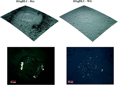 | ||
| Fig. 7 IFM 3D profile and optical microscope images of the Alumina counterparts after tests against 10AgDLC in dry and lubricated conditions. | ||
Friction in the different formulated lubricants varied significantly as shown in Fig. 6. Table 6 shows the average friction along with the electrical conductivity of the lubricants for different testing conditions of the Ag-doped DLC after friction stabilization. It can be seen that the friction is high for WGC12 and WGIM, and lower for WGPP and WGBMP, being the lowest for WGPP. In this case, the trend does not follow the electrical conductivity and therefore the surface electron-transfer does not control friction evolution in this case. Ag is a non-carbide forming element in DLCs and it will therefore act as a metal on the surface. This metallic behaviour will create electrochemical activation sites that will control the adsorption of the additives to the surface in the different fluids consequently affecting friction.
| Dry | WG | WGC12 | WGIM | WGPP | WGBMP | |
|---|---|---|---|---|---|---|
| CoF | 0.105 | 0.131 | 0.131 | 0.121 | 0.089 | 0.106 |
| Conductivity (μS cm−1) | — | 2.5 | 4.3 | 401.1 | 211.2 | 109.3 |
To understand the electrochemical activation process of the Ag sites, a potentiodynamic polarization study of 10AgDLC in the formulated lubricants was conducted. Fig. 8 shows the potentiodynamic polarization curves of 10AgDLC in the formulated water–based lubricants.
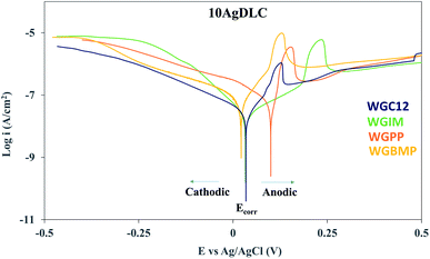 | ||
| Fig. 8 Potentiodynamic polarization curves of 10AgDLC in different additivated water–base lubricants (the Ecorr and anodic and cathodic regions are indicated for WGC12). | ||
In the anodic polarization branch (above the Ecorr), an increase in current density is observed for all formulations right at the beginning. This peak in the anodic current density is due to the oxidation of Ag,51 and it can be understood as a sign of activation of the Ag sites on the surface, providing active adsorption sites for the additive species. If the electrochemical potential in equilibrium (Ecorr) and the potential of the Ag oxidation peak (Epeak) are considered, the potential difference between them (ΔEactivation) can be understood as the driving force for surface adsorption. The potential difference is thus the needed polarization to activate the Ag adsorption sites. Table 7 summarizes the Ecorr, Epeak and ΔEactivation extracted from the polarization curves shown in Fig. 8, the potential drop during the tribocorrosion tests (ΔEtribo) extracted from Fig. 4, and the average CoF after stabilization for 10AgDLC in the formulated lubricants.
| WGC12 | WGIM | WGPP | WGBMP | |
|---|---|---|---|---|
| Ecorr (mV vs. Ag/AgCl) | +34 | +33 | +100 | +22 |
| Epeak (mV vs. Ag/AgCl) | +130 | +238 | +156 | +129 |
| ΔEactivation (mV) | 96 | 205 | 56 | 107 |
| ΔEtribo (mV) | 103 | 91 | 123 | 80 |
| CoF | 0.131 | 0.121 | 0.089 | 0.106 |
In the tribocorrosion tests performed at OCP (Fig. 4) a potential drop was observed at the onset of rubbing. As the rubbing starts in a tribotest, the electrochemical state of the sample is not in equilibrium anymore and the galvanic couple established between the wear track and the rest of the surface leads to the polarization of the regions inside wear track to more anodic potentials, while the regions outside wear track polarize to more cathodic potentials. Since the area of the wear track is significantly smaller than the area outside the wear track, the potential during rubbing drops to cathodic values. However, the wear track is anodically polarized and there is an anodic current density in the wear track during a tribocorrosion test at OCP.52 This means that a larger cathodic potential drop during rubbing will result in more anodic current flow in the wear track, i.e. more oxidation of Ag sites. Thus, if the wear track polarizes to values equal or above the Epeak, the electrochemical activation of the adsorption sites can occur. As mentioned earlier, the ΔEactivation is the driving force controlling the probability of the activation of the Ag sites on the surface. Thus, by calculating the potential drop during rubbing (ΔEtribo) and comparing it to the ΔEactivation, it is possible to know which of the lubricant additives will be able to overcome the energy barrier to activate the adsorption sites. Indeed, only WGPP (Table 7) is able to overcome the energy barrier for activating the Ag sites since its ΔEtribo is the largest and its ΔEactivation is the smallest among all additivated lubricants. This results in the highest adsorption rate of all additives and the lowest friction. In all other cases, the anodic polarization in the wear track is not sufficient to overcome the ΔEactivation and therefore the surface sites are not activated. Indeed, the largest ΔEactivation is found for WGIM (205 mV), and the low ΔEtribo (91 mV) leads to the largest barrier to overcome, whereas in the case of WGBMP this barrier is less. Therefore, the lowest adsorption rate and the highest friction of all ILs is found for WGIM.
An interesting case is WGC12 with a very similar ΔEtribo and ΔEactivation, but with the highest friction of all lubricated tests (same as the non-additivated WG). Friction starts below 0.1 and gradually increases throughout the test (Fig. 6). This is due to the very low electrical conductivity of WGC12 (similar to WG alone, see Table 6). In this case, there is a larger ohmic drop compared to the IL-additivated lubricants. This large ohmic drop acts as a barrier against the activation of the surface sites. To prove this, potentiostatic tribocorrosion tests at the anodic potentials of +130 (Epeak), +230 and +330 mV were performed. Fig. 9 shows the friction evolution with time of the potentiostatic tests of 10AgDLC in WGC12 together with the friction evolution of the tribocorrosion tests at OCP for comparison.
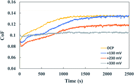 | ||
| Fig. 9 CoF evolution during the potentiostatic tribotests of 10AgDLC in WGC12 at different anodic potentials. | ||
Fig. 9 shows that for a very low conductivity medium (WGC12), the anodic polarization in the wear track due to the galvanic coupling (ΔEtribo in the OCP test) is not enough to activate the surface adsorption sites for the lubricant additives since friction does not decrease when polarizing at +130 mV (Epeak). In order to achieve lower friction (i.e. activate adsorption sites), larger anodic polarization must be applied due to the ohmic drop effect. Indeed, it was found that the friction evolution at +230 mV and +330 mV was lower than when polarizing at Epeak (0.118 and 0.105, respectively). This confirms that in a low conductivity medium, the ohmic drop controls the activation of the adsorption sites. Therefore, in low conductivity media, friction can be controlled by anodic polarizing well above the ΔEactivation.
In the case of high conductivity media, potentiodynamic triboelectrochemical tests were performed to understand better the effect of the electrochemical potential on the activation of the surface adsorption sites. The triboelectrochemical tests were carried out in the tribometer equipped with a three-electrode tribocorrosion cell: DLC surface as working electrode, Ag/AgCl saturated KCl as reference electrode and a Pt wire as counter electrode. During the first 500 cycles of rubbing, the electrochemical potential was set at the measured OCP of the coating. After that, the anodic potentiodynamic polarization of the surface started with the scan rate of 0.1 mV s−1 and lasted for 4500 seconds of rubbing at the same contact conditions as the OCP tribocorrosion tests. The tests were repeated at least twice to check the repeatability. Fig. 10 shows the potentiodynamic anodic curve of 10AgDLC coating in WGPP and WGIM together with the evolution of friction during the test. The friction evolution during the OCP tests (from Fig. 6) is also included for comparison.
 | ||
| Fig. 10 Anodic polarization curves together with CoF evolution during the potentiodynamic tribocorrosion tests of 10AgDLC in WGPP and WGIM. | ||
The anodic potentiodynamic polarization curves obtained during the tribocorrosion test (Fig. 10) show that the Epeak in WGPP rises after 500 seconds of sliding, and it needs 2500 s in the case of WGIM. In both cases, friction decreases at the onset of Epeak, being this decrease more pronounced for WGIM. For WGPP, the friction value in the potentiodynamic test is slightly lower than that of the OCP test at the start, but it stabilizes at the same value as for the OCP test. This indicates that the external anodic polarization of the surface in WGPP does not make any significant difference in the activation of the surface adsorption sites. This is not surprising since it was already shown that WGPP had a very low activation barrier to overcome (ΔEactivation, Table 7) and therefore, the galvanically couple formed after polarizing at OCP is sufficient to activate the necessary sites for an efficient additive adsorption. However, WGIM had the largest ΔEactivation (Table 7) and therefore, the onset of surface activation sites corresponds to the Epeak at which a clear friction decrease is observed in Fig. 10. Interestingly, as the polarizing potential reaches about 200 mV (which is the ΔEactivation for WGIM), friction evolution shows a linear decline.
5. Conclusions
Three different types of diamond like carbon coatings (undoped, 10 at% W-doped and 10 at% Ag-doped) have been studied in dry and lubricated conditions. The lubricants were water–glycol based formulated with a classical organic friction modifier (C12) and ionic liquids. An electrochemical approach to control friction was taken by performing tribocorrosion tests at OCP, potentiostatic and potentiodynamic conditions to investigate the coating-additive interactions. The findings of this study can be summarized as follows:• Both tungsten and silver doping resulted in a decrease of hardness and elastic modulus. XPS spectra showed that the mechanical behaviour is controlled by the sp3/sp2 ratio and the formation of WC in the W-dopped coating. Ag is a non-carbide forming dopant in DLC resulting in better adhesion to the substrate and lower residual stresses. The undoped DLC coating had the lowest adhesion to the substrate and lowest ductility.
• Undoped DLC failed in all the tribological tests, and partial or full coating removal of the coating was observed.
• In dry conditions, 10AgDLC showed the lowest friction, which is due to the inherent solid lubrication properties of silver.
• In lubricated conditions, W-dopped DLC showed the lowest friction of all coatings. In this case, the friction evolution was controlled by an electron-transfer mechanism. This mechanism is driven by the electrical conductivity of the medium and therefore, the lowest friction was found for the lubricant with the highest electrical conductivity (i.e. formulated with IM). Since the surface of the DLC coatings is negatively charged, the deprotonated molecules of C12 were repelled from the surface resulting in the same friction as the non-formulated water–glycol base fluid.
• In lubricated conditions, the friction of Ag-doped DLC was slightly higher than for WDLC and was electrochemically controlled. The polarization curve of 10AgDLC in the formulated water-based lubricants revealed a current density peak in the anodic branch. This peak is related to the oxidation of silver. The tribocorrosion tests showed that the potential difference (ΔEactivation) between the Ecorr and the peak potential (Epeak) is the energy needed to activate the surface adsorption sites. The potentiodynamic tribocorrosion tests confirmed that friction could be controlled by increasing the electrochemical potential for the IL-formulated lubricants. In the case of C12, the ohmic drop due to the very low electrical conductivity of the lubricant resulted in the need of higher anodic potentials to activate the surface adsorption sites.
• The potentiostatic and potentiodynamic tribocorrosion tests prove that the concept of “electrochemically-controlled friction” can be achieved in IL-formulated water-based lubricants with non-carbide forming metal doped DLCs. In the case of carbide forming metal doped DLCs, friction is controlled by the electrical conductivity of the medium via an electron-transfer mechanism.
Conflicts of interest
There are no conflicts to declare.Acknowledgements
The authors would like to acknowledge the financial support from the M-ERA.NET GreenCOAT project with project number 4153 as well as the financial support from The Research Council of Norway. Norwegian Micro- and Nano-fabrication facility, NorFab, is also acknowledged for providing the characterization facilities.References
- K. Holmberg and A. Erdemir, Tribol. Int., 2019, 135, 389–396 CrossRef.
- K. Holmberg and A. Erdemir, Friction, 2017, 5, 263–284 CrossRef CAS.
- K. Holmberg, P. Andersson and A. Erdemir, Tribol. Int., 2012, 47, 221–234 CrossRef.
- L. I. Farfan-Cabrera, Tribol. Int., 2019, 138, 473–486 CrossRef.
- Y. Chen, S. Jha, A. Raut, W. Zhang and H. Liang, Mech. Eng., 2020, 6, 571464 Search PubMed.
- A. Gupta, Characterization of engine and transmission lubricants for electric, hybrid and plug-in hybrid vehicles, The Ohio State University, 2012 Search PubMed.
- V. W. Wong and S. C. Tung, Friction, 2016, 4, 1–28 CrossRef CAS.
- Y. Zhou and J. Qu, ACS Appl. Mater. Interfaces, 2017, 9, 3209–3222 CrossRef CAS PubMed.
- H. Khanmohammadi, W. Wijanarko and N. Espallargas, Tribol. Lett., 2020, 68, 1–15 CrossRef.
- Y. Zhou, J. Dyck, T. W. Graham, H. Luo, D. N. Leonard and J. Qu, Langmuir, 2014, 30, 13301–13311 CrossRef CAS PubMed.
- M.-D. Bermúdez, A.-E. Jiménez, J. Sanes and F.-J. Carrión, Molecules, 2009, 14, 2888–2908 CrossRef PubMed.
- N. Dörr, A. Merstallinger, R. Holzbauer, V. Pejaković, J. Brenner, L. Pisarova, J. Stelzl and M. Frauscher, Tribol. Lett., 2019, 67, 1–18 CrossRef.
- P. Wasserscheid and T. Welton, Ionic liquids in synthesis, Wiley Online Library, 2008 Search PubMed.
- H. Xiao, Tribol. Trans., 2017, 60, 20–30 CrossRef CAS.
- G. Huang, Q. Yu, Z. Ma and M. Cai, Tribol. Int., 2017, 107, 152–162 CrossRef CAS.
- S. Perkin, Phys. Chem. Chem. Phys., 2012, 14, 5052–5062 RSC.
- J. Qu, M. Chi, H. M. Meyer, P. J. Blau, S. Dai and H. Luo, Tribol. Lett., 2011, 43, 205–211 CrossRef CAS.
- D. Li, M. Cai, D. Feng, F. Zhou and W. Liu, Tribol. Int., 2011, 44, 1111–1117 CrossRef CAS.
- M. Itoga, S. Aoki, A. Suzuki, Y. Yoshida, Y. Fujinami and M. Masuko, Tribol. Int., 2016, 93, 640–650 CrossRef CAS.
- F. Su, G. Chen and J. Sun, Tribol. Int., 2019, 130, 1–8 CrossRef CAS.
- T. Zhang, Q. Deng, B. Liu, B. Wu, F. Jing, Y. Leng and N. Huang, Surf. Coat. Technol., 2015, 273, 12–19 CrossRef CAS.
- J. Liu, X. Wang, B. Wu, T. Zhang, Y. Leng and N. Huang, Vacuum, 2013, 92, 39–43 CrossRef CAS.
- X. Guan, Z. Lu and L. Wang, Tribol. Lett., 2011, 44, 315–325 CrossRef CAS.
- Y. Wang, L. Wang and Q. Xue, Surf. Coat. Technol., 2011, 205, 2770–2777 CrossRef CAS.
- G.-H. Zhao, R. E. Aune and N. Espallargas, J. Mech. Behav. Biomed. Mater., 2016, 63, 100–114 CrossRef CAS PubMed.
- Y. Ye, Y. Wang, X. Ma, D. Zhang, L. Wang and X. Li, Diamond Relat. Mater., 2017, 79, 70–78 CrossRef CAS.
- Z. M. Wang, J. Zhang, X. Han, Q. F. Li, Z. L. Wang and R. Wei, Corros. Sci., 2014, 86, 261–267 CrossRef CAS.
- M. Azzi, M. Paquette, J. Szpunar, J. Klemberg-Sapieha and L. Martinu, Wear, 2009, 267, 860–866 CrossRef CAS.
- L. Cao, J. Liu, Y. Wan and J. Pu, Diamond Relat. Mater., 2020, 109, 108019 CrossRef CAS.
- S. Zhang, H. T. Johnson, G. J. Wagner, W. K. Liu and K. J. Hsia, Acta Mater., 2003, 51, 5211–5222 CrossRef CAS.
- M. Evaristo, F. Fernandes and A. Cavaleiro, Coatings, 2020, 10, 319 CrossRef CAS.
- N. Manninen, F. Ribeiro, A. Escudeiro, T. Polcar, S. Carvalho and A. Cavaleiro, Surf. Coat. Technol., 2013, 232, 440–446 CrossRef CAS.
- S. Bernat, S. Armada and N. Espallargas, Tribol. Lett., 2018, 66, 1–12 CrossRef.
- A. Matthews, S. Franklin and K. Holmberg, J. Phys. D: Appl. Phys., 2007, 40, 5463 CrossRef CAS.
- W. Yue, C. Liu, Z. Fu, C. Wang, H. Huang and J. Liu, Tribol. Lett., 2015, 58, 1–10 CrossRef CAS.
- ASTM C1624 – 05, DOI:10.1520/C1624-05R15.
- L. Patnaik, S. R. Maity and S. Kumar, Ceram. Int., 2020, 46, 22805–22818 CrossRef CAS.
- P. Jing, D. Ma, Y. Gong, X. Luo, Y. Zhang, Y. Weng and Y. Leng, Surf. Coat. Technol., 2021, 405, 126542 CrossRef CAS.
- A.-Y. Wang, K.-R. Lee, J.-P. Ahn and J. H. Han, Carbon, 2006, 44, 1826–1832 CrossRef CAS.
- M. Constantinou, M. Pervolaraki, P. Nikolaou, C. Prouskas, P. Patsalas, P. Kelires, J. Giapintzakis and G. Constantinides, Surf. Coat. Technol., 2017, 309, 320–330 CrossRef CAS.
- A. I. Munoz, N. Espallargas and S. Mischler, Tribocorrosion, Springer, 2020 Search PubMed.
- Y. Liu, A. Erdemir and E. Meletis, Surf. Coat. Technol., 1996, 82, 48–56 CrossRef CAS.
- Y. Liu and E. Meletis, J. Mater. Sci., 1997, 32, 3491–3495 CrossRef CAS.
- L. Pastewka, S. Moser and M. Moseler, Tribol. Lett., 2010, 39, 49–61 CrossRef CAS.
- A. Erdemir and C. Donnet, J. Phys. D: Appl. Phys., 2006, 39, R311 CrossRef CAS.
- M. Jelínek, K. Smetana, T. Kocourek, B. Dvořánková, J. Zemek, J. Remsa and T. Luxbacher, Mater. Sci. Eng. B, 2010, 169, 89–93 CrossRef.
- M. Jelínek, T. Kocourek, J. Remsa, J. Mikšovský, J. Zemek, K. Smetana, B. Dvořánková and T. Luxbacher, Appl. Phys. A: Mater. Sci. Process., 2010, 101, 579–583 CrossRef.
- Y. Wang, J. Wang, G. Zhang, L. Wang and P. Yan, Surf. Coat. Technol., 2012, 206, 3299–3308 CrossRef CAS.
- N. K. Manninen, R. E. Galindo, S. Carvalho and A. Cavaleiro, Surf. Coat. Technol., 2015, 267, 90–97 CrossRef CAS.
- Y. Wu, J. Chen, H. Li, L. Ji, Y. Ye and H. Zhou, Appl. Surf. Sci., 2013, 284, 165–170 CrossRef CAS.
- B. Abduali, T. Elmira and T. Ainur, Orient. J. Chem., 2013, 29, 33–37 CAS.
- N. Espallargas, R. Johnsen, C. Torres and A. Muñoz, Wear, 2013, 307, 190–197 CrossRef CAS.
| This journal is © The Royal Society of Chemistry 2022 |


