 Open Access Article
Conductive polymer doped two-dimensional MXene materials: opening the channel of magnesium ion transport
Ruinan Zhang ,
Qing Liu,
Zhizheng Wang,
Xiaodong Yang and
Yuxiang Guo*
Department of Materials Science & Engineering, University of Science and Technology Liaoning, Anshan, 114051, China. E-mail: gyxzlwy@163.com
First published on 2nd February 2022
Abstract
MXene has a series of advantages, such as high specific surface and conductivity, abundant surface functional groups, and effectively accelerating the electron conduction of electrochemically active sites. It is worth noting that due to the van der Waals force between MXene layers, the layers attract each other and the layer spacing becomes smaller, which cannot give full scope to the performance of MXene. Therefore, we introduce a conductive polymer PANI. The purpose of introducing acidified PANI to construct PANI/Ti3C2 composites is to make full use of the conductive framework of Ti3C2, the abundant functional groups on the surface, and the synergistic effect between the composites, to alleviate the stacking of Ti3C2 layers by occupying the active sites on the surface of Ti3C2 with PANI. At the same time, the proportion of PANI is changed to 40% of Ti3C2, and the composite when used as the cathode of magnesium ion batteries shows a mass-specific capacity of 132.2 mA h g−1 and a series of excellent electrochemical properties at 50 mA g−1 current. This provides a new design idea for the subsequent development of high-performance magnesium storage cathode materials.
1. Introduction
Due to the rapid development of society, there is greater demand for portable equipment and large energy storage systems,1 and the excessive use of nonrenewable energy such as coal and oil has caused problems such as air pollution, water resource pollution, and global warming,2 making secondary batteries stand out among many new energy storage devices and receive extensive attention. Due to their high energy and power density, lithium-ion batteries (LIBs) are still in a leading position in the field of electric energy storage and have realized large-scale commercial applications.3,4 However, the disadvantages of LIBs restrict their further development.5,6 Firstly, lithium metal is not abundant in nature, which leads to resource shortages after large-scale development. In addition, when lithium metal is used as the negative electrode, it will have a side reaction with the electrolyte, resulting in harmful lithium dendrites piercing the diaphragm, which will do great harm to the safety of the battery.7 Magnesium ion batteries (MIBs) are an alternative, which may provide a more economical and safe energy storage unit for future energy storage equipment.8 Magnesium and lithium are located diagonally in the periodic table of elements, which indicates that their chemical properties are similar. As for its reserves, magnesium metal in the earth ranks sixth in the list of elements, which reduces the production cost when used as the electrode material of batteries.Since the valence of magnesium ion is +2 and lithium ion is +1, each Mg2+ can theoretically transfer twice the charge of Li+ during charge and discharge, so that it has higher energy and higher energy density. Table 1 shows the chemical properties between magnesium metal and lithium metal.9
| Parameter | Magnesium metal | Lithium metal |
|---|---|---|
| Relative atomic mass | 24.31 | 6.941 |
| Safety factor | Safer | More dangerous |
| Electrode potential/V | −2.369(acidic)/−2.68(alkalinity) | −3.04 |
| Ion radius/nm | 0.067 | 0.069 |
| Theoretical capacity/mA h g−1 | 3863 | 2206 |
| Metal price/¥ per kg | 18 | 405 |
| Melting point/°C | 650 | 181 |
Magnesium metal has a high melting point and boiling point.10 It will not react with electrolytes to form dendrites in the process of electrochemical reaction, and will not cause harm like LIB in the process of use, to ensure the safety performance of the battery. Therefore, MIBs have been widely studied and developed rapidly in recent years.11 However, during the research, it was found that there are still great differences in the reaction mechanism between LIB and MIB. Due to the charge characteristics of magnesium ions, the rate of magnesium ions in the electrochemical migration process is forced to decrease, resulting in that many materials cannot be used for the storage of magnesium ions.12,13 On the other hand, when magnesium metal contacts the electrolyte as a negative electrode, a passive film will be generated on its surface, affecting ion transmission.14–16 In conclusion, the most important thing to determine the development speed of MIB is to explore a good, stable electrode material and electrolyte solution that can facilitate the insertion and removal of Mg2+. High specific capacity, good cycle stability, and fast and reversible ion migration are the characteristics of ideal cathode materials.
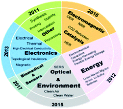
MXene with many potentials in energy storage and conversion has attracted much attention.2 MXene is a novel and rapidly developing two-dimensional transition metal carbide, nitride or carbonitride,17–19 and its expression is Mn+1XnTx (M usually represents transition metal element, X represents C or N element, and Tx represents surface functional group). Fig. 1 shows the applications and properties of MXene from 2011 to 2019.20
Many materials can improve the performance of MXene materials, for example, the introduction of graphene and carbon nanotube (CNT), tin(IV) oxide (SnO2) and iron(III) oxide (Fe2O3) can greatly increase the layer spacing of MXene, thus directly increasing the ion transfer rate. This proves that the intercalation or modification of MXene helps to prevent stacking, increase ion adsorption sites and enhance electrochemical performance.21
Lukatskaya et al.19 found that the specific surface of the material can reach 98 m2 g−1, and it is from by etching the “A” layer in the middle of the MAX phase (the expression is Mn+1AXn, n = 1, 2 or 3).22,23 Ti3C2 is the transition metal carbide with the longest and most extensive research time in the two-dimensional MXene family. It has typical electric double-layer capacitance characteristics and an ideal electrode material. This layered structure provides a 2D transmission channel and effective Mg2+ insertion site. It has high conductivity, effectively accelerates the electron conduction of electrochemically active sites,23–25 and improves the storage capacity of Mg2+. At the same time, there is a classical strong covalent bond between Ti and C atoms, and it has hydrophilicity due to the introduction of functional groups on its surface after etching, which is theoretically conducive to the infiltration of electrolyte and makes it have redox activity, to achieve higher capacity.20–26
However, in practical application, the collapse and stacking between layers are not conducive to the infiltration of electrolytes, resulting in low specific capacitance, which limits its research and application in supercapacitors to a certain extent. The main reaction27,28 is as follows:
 | (1) |
In 2014, Xie et al.29 simulated and calculated the Mg storage performance of MXene through density functional theory (DFT). They found that MXene multilayer nanosheets can realize the adsorption of Mg through a series of storage mechanisms. In the same year, some scholars30 found that the introduction of alkali metal fluoride in the preparation of Ti3C2 can be intercalated into the Ti3C2 layer, expanding the layer spacing of Ti3C2, and reducing the van der Waals force between Ti3C2 layers. Zhao31 prepared RuO2/Ti3C2Tx composites modified by phosphate ions. On the one hand, doping phosphate ions can effectively improve the pseudocapacitance activity of RuO2, on the other hand, it can improve the conductivity of Ti3C2Tx materials. Its layered structure and RuO2 act as support carriers, which can not only prevent the aggregation of RuO2 particles, but also prevent the collapse and stacking of Ti3C2 layers. At a current density of 2 A g−1, the specific capacity of the composite can reach 612.7 F g−1. Fan et al.32 embedded graphene into MXene layers. The presence of graphene effectively inhibited the structural stacking of MXene during charge and discharge, and the volume-specific capacity could reach 1445 F cm−3 at a scanning rate of 2 mV s−1. Through the efforts of so many scholars, it is not difficult to find that one of the keys to making full use of the excellent properties of MXene materials is to solve the problem of sheet collapse and stacking, increase the layer spacing and reduce the van der Waals force between layers.
Conductive polymer polyaniline (PANI) has become a research hotspot in recent years because of its diversified molecular structure, high conductivity and electrochemical reversibility.33,34 PANI has a high theoretical specific capacity, good chemical properties and orderly controllable chain structure, but the movement of its internal free charge is limited, so the conductivity of most intrinsic polymers is poor. However, when the conductive polymer material is in the doped state, that is, after doping with an acid solution, its conductivity is significantly improved and its electrical activity is enhanced. The doping of polyaniline is reversible. When PANI is doped with impurity daughter acid, it forms dark green doped PANI, which is a primary doped PANI. When the doped PANI is in alkaline condition, PANI will be undoped and return to the eigenstate. PANI was acidly doped again to form secondary doped PANI. According to the research, secondary doped PANI has a higher yield and better properties than primary doped PANI. Fig. 2 shows the basic structure diagram of PANI.
Wang et al.35 prepared PANI/GO composites by electrochemical synthesis method, and explored the electrical properties of the composites. It was found that the specific capacitance reached 500 F g−1, which could still maintain 81% after 2000 cycles of charge and discharge. Armes et al.36 prepared PANI by chemical oxidation method, (NH4)2S2O8 is considered to be the most ideal oxidant, and the electrochemical performance of PANI is the best when the dosage ratio of oxidant to aniline monomer is 1![[thin space (1/6-em)]](https://www.rsc.org/images/entities/char_2009.gif) :
:![[thin space (1/6-em)]](https://www.rsc.org/images/entities/char_2009.gif) 1.
1.
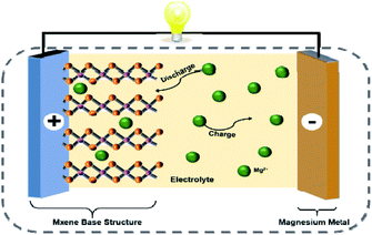
In this paper, two-dimensional MXene is used as the substrate and doped PANI is introduced to construct MXene matrix composites. The purpose is to make full use of MXene's conductive skeleton, surface rich functional group modification and the synergistic effect between composites, alleviate the stacking of MXene layers, increase the layer spacing and specific surface area of MXene materials, enhance the structural stability of materials, and open the ion transport channel of magnesium ion battery. Fig. 3 shows the schematic diagram of magnesium ion battery with MXene as cathode material.
2. Experimental materials and methods
2.1 Preparation of Ti3C2
1 g Ti3AlC2 powder is fully ground in a mortar. Slowly add 15 ml of 49% HF solution to the beaker containing the sample, place it in the fume hood and soak for 24 hours. The samples were centrifuged alternately with deionized water and absolute ethanol solution several times until the supernatant was close to neutral. The washed sample was placed in a vacuum drying oven and dried at 60 °C for 24 hours to obtain Ti3C2 powder.2.2 Preparation of PANI/Ti3C2 composites
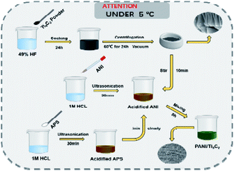
The most common method for preparing PANI is chemical oxidation. This method mainly oxidizes aniline monomer with oxidant in an acidic solution to obtain doped PANI oxidants, including but not limited to ammonium persulfate ((NH4)2S2O8), potassium persulfate (K2S2O8) and hydrogen peroxide (H2O2). We made changes in the synthesis process. The specific preparation process is as follows: 93.14 μl aniline monomer (ANI) was dissolved into 10 ml 1 m hydrochloric acid (HCl) for ultrasonication for 30 min. In addition, 24.5 mg ammonium persulfate (APS) was dissolved in 10 ml 1 m hydrochloric acid for ultrasonic 30 min. Take 0.1 g of prepared Ti3C2 powder, add it into acidified aniline solution, stir it for 10 min with the help of a magnetic stirrer, and slowly add the prepared APS solution. With the progress of the reaction, the color of the solution becomes dark green. After 8 h, the dark green product was centrifuged and washed several times, and the material was dried completely at 50 °C in the vacuum drying oven. In the above experimental steps, the PANI mass is 10% of Ti3C2. Repeat the operation and increase the ANI and APS mass to 20%, 30%, 40% and 50% of Ti3C2, marked P1, P2, P3, P4 and P5 respectively. Fig. 4 shows the overall experimental idea and process.2.3 Characterization of materials
The crystal structure of the sample was determined by an X-ray diffractometer (XRD) with scanning angle 2θ = 5°–65°. The microstructure and morphology of the prepared materials were characterized by a field emission scanning electron microscope (SEM). SEM is one of the most effective analysis methods in the field of material synthesis.2.4 Electrochemical performance test
The sample, conductive agent (acetylene black), and binder (PVDF) were ground successively in the mortar according to the mass ratio at 8![[thin space (1/6-em)]](https://www.rsc.org/images/entities/char_2009.gif) :
:![[thin space (1/6-em)]](https://www.rsc.org/images/entities/char_2009.gif) 1
1![[thin space (1/6-em)]](https://www.rsc.org/images/entities/char_2009.gif) :
:![[thin space (1/6-em)]](https://www.rsc.org/images/entities/char_2009.gif) 1, then the dispersant (NMP) was added to grind again until the slurry had no obvious particle feeling and smeared on the copper foil. The thickness of the coating was about 25 μm. The cathode electrode sheet was obtained by vacuum drying for 12 h at 120 °C. The magnesium sheet was cut into a disc with a diameter of about 15 mm and a thickness of 1 mm as an anode sheet. 0.4 mol L−1 (PhMgCl)2–AlCl3/THF solution was selected as electrolyte and assembled CR2032 standard button battery.
1, then the dispersant (NMP) was added to grind again until the slurry had no obvious particle feeling and smeared on the copper foil. The thickness of the coating was about 25 μm. The cathode electrode sheet was obtained by vacuum drying for 12 h at 120 °C. The magnesium sheet was cut into a disc with a diameter of about 15 mm and a thickness of 1 mm as an anode sheet. 0.4 mol L−1 (PhMgCl)2–AlCl3/THF solution was selected as electrolyte and assembled CR2032 standard button battery.
Relevant electrochemical tests were carried out at room temperature with the help of the Land2100 charge–discharge tester and CHI660E electrochemical workstation.
3. Results and discussion
3.1 XRD and SEM analysis
The comparison of diffraction peaks in XRD spectrums (Fig. 5) can determine the interior of the composite simultaneously containing PANI and Ti3C2 fixed characteristic diffraction peaks. This indicates the material structure has not changed, which is only a physical process. There are diffraction peaks in the Ti3C2 sample at 2θ of 8.6°, 18.1°, 27.5°, 35.9° and 60.6°, corresponding to (002), (004), (008), (0010) and (110) crystal planes. After consulting literature,37,38 it is known that polyaniline has characteristic peaks near 24.5° and 26°, which belong to (110) and (200) crystal planes. In Fig. 5(a), the diffraction peaks in the pink shadow are all PANI and Ti3C2 in the yellow shadow. Interestingly, with the increase of PANI content, the representative peaks become stronger and stronger, and the peaks tend to have small angles. Therefore, in the small angle diffraction diagram, showing in Fig. 5(b), the original 8.6° peak of Ti3C2 shifts to 8° after doping PANI. According to the Bragg formula, the layer spacing of Ti3C2 is 0.99 nm, The PANI/Ti3C2 layer spacing is 1.1 nm, which may be due to the expansion of the layer spacing after PANI is loaded on the active site exposed by Ti3C2.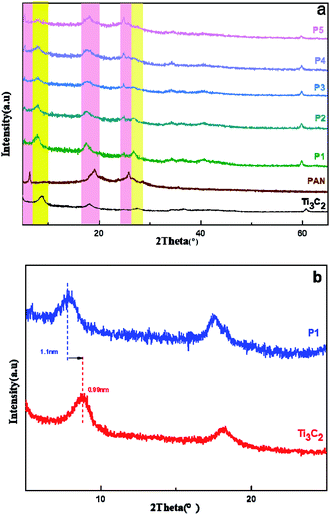 | ||
| Fig. 5 (a) The diffraction peaks of PANI/Ti3C2 composite materials; (b) the small-angle diffraction diagram. | ||
Fig. 6(a) can be seen that Ti3C2 presents an “accordion-like” nanostructure. Due to the large van der Waals force between T3Al2 layers, the layered structure is closely combined, the layer spacing is very small, and the specific surface area cannot be fully utilized. Fig. 6(b–f) are SEM images of PANI/Ti3C2 composites with PANI mass ranging from 10–50%. Under different magnification, it is not difficult to find that the “small particles” on the surface are from nothing to more, but Ti3C2 in Fig. 6(b and c) are damaged to varying degrees. This may be due to the low content of PANI and the failure of PANI to “build a strong protective layer” on the surface during the subsequent long-term reaction or centrifugation process, destroying the basic structure. In Fig. 6(f), the microstructure is relatively dense compared to others. Due to the excessive content of PANI, the appropriate reaction sites cannot be found for it and began to accumulate on the surface of Ti3C2, blocking the channels between the original layers, and there is not enough space to buffer the expansion of the material, reduce the ion transmission path to a certain extent, resulting in the gradual differentiation and failure of the material. In Fig. 6(d and e), the layered structure of Ti3C2 base material can be clearly seen, the reaction site exposed by T3Al2 losing Al can be fully utilized to provide more channels for Mg2+ transmission and better show the excellent specific surface area characteristics of Ti3C2. The gap between particles or lamellae can effectively adapt to the volume change in the process of charge and discharge, to show better cycle stability. We can boldly guess that the content of PANI is related to the performance of the MIB.
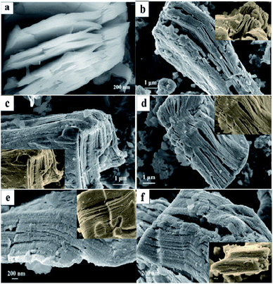 | ||
| Fig. 6 SEM images of PANI/Ti3C2 composite materials: (a)Ti3C2; (b) P1; (c) P2; (d) P3; (e) P4; (f) P5. | ||
3.2 Electrochemical performance analysis
We verify the above conjecture by electrochemical detection and analysis. Fig. 7(a) shows the constant current charge and discharge cycle data of the first 20 cycles of PANI/Ti3C2 composites with different contents under 50 mA g−1 current. Fig. 7(b) summarizes the 1st, 2nd, 20th charge and discharge cycle and the capacity retention. It is not difficult to see that the specific discharge capacity of PANI/Ti3C2 composites for the first charge and discharge under five different ratios is 50.1 mA h g−1, 77.5 mA h g−1, 105.9 mA h g−1, 132.2 mA h g−1, 98.3 mA h g−1. After 20 cycles, the specific discharge capacity is 21.9 mA h g−1, 50.3 mA h g−1, 69.2 mA h g−1, 93 mA h g−1, 56.7 mA h g−1 respectively. The discharge specific capacity and cycle retention rate of the composite reach the peak of 132.2 mA h g−1 and 70.3% when the PANI content is 40%. Therefore, it can be concluded that when the PANI content in the PANI/Ti3C2 composite reaches 40%, the composite shows the best capacity as the cathode material of magnesium ion battery.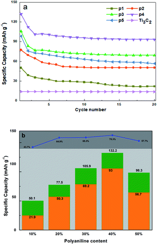 | ||
| Fig. 7 (a) The first 20 constant current charge–discharge cycles of P1–P5 and Ti3C2; (b) trend summary and the capacity retention. | ||
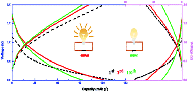
Then P4 (left part) and P1 (right part) in Ti3C2/PANI composites are selected for charge and discharge cycle stability test. The curves of the first, second and 100 charge–discharge cycles are shown in Fig. 8. It can be seen from the curve that the first discharge curve of P4 has a relatively flat platform at the voltage of 0.6 V and 0.2 V respectively, while the discharge curve of P1 only has a platform at the voltage of about 0.1 V. It is not difficult to observe these charge–discharge curves. With the progress of the cycle, the shape of the charge–discharge curve of P4 is only significantly different from that of the first cycle, while the shape of the later cycle curve is roughly similar and the overlap is higher and higher. But the coincidence degree of the charge–discharge curve of P1 still cannot reach the ideal state after 100 cycles. This shows that doping PANI in Ti3C2 can effectively improve the cycle stability of the composites, and the content of 40% is the best effect.
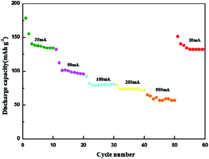
Fig. 9 shows the rate performance under different current densities. Under the current densities of 20 mA g−1, 50 mA g−1, 100 mA g−1, 200 mA g−1 and 500 mA g−1, the corresponding reversible capacity is 178.4 mA h g−1, 132.2 mA h g−1, 92.6 mA h g−1, 79 mA h g−1, 65.09 mA h g−1 respectively. When the low current of 20 mA g−1 is returned, the battery still maintains a stable reversible capacity of 151.3 mA h g−1. With the increase of current, the capacity of the composite tends to be stable, and it can still show amazing capacity when it returns to low current again. The excellent capacity retention in a wide rate range indicates that PANI/Ti3C2 composite may be a promising highspeed cathode candidate for MIBs.
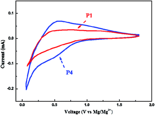
To further evaluate the electrochemical properties of the composites, the cyclic voltammetry test of PANI/Ti3C2 materials was continued, and the results are shown in Fig. 10. It can be seen from the figure that there are obvious redox peaks in the cyclic voltammetry curve of P4 material, and the peaks at the discharge voltage of about 0.6 V and 0.2 V correspond to the two platforms of charge–discharge cycle; however, a weak redox peak appeared only at 0.1 V in P1, which corresponds to the only platform of its charge discharge cycle. In contrast, 40% PANI/Ti3C2 electrode shows a larger CV area and obvious cathode and anode current response, indicating obvious capacity contribution. The observed sharp peak below 0.2 V is related to the insertion of Mg2+ into the active site of the electrode with higher activation energy. When the PANI content is 40%, it can more effectively weaken the van der Waals force between the layers of the base material, to alleviate the stacking of Ti3C2 layers, make full use of the synergistic effect between the composites, increase the layer spacing, specific surface area and structural stability of PANI/Ti3C2 composites, and improve the transmission rate of magnesium ions.
4. Conclusion
In this experiment, Ti3C2 was selected as the substrate, and the doped acidified conductive polymer PANI was used as the cathode material of magnesium ion electrode. The results showed that when the content of PANI in PANI/Ti3C2 composite reached 40%, the micromorphology was complete and clear, and the specific discharge capacity could reach 132.2 mA h g−1 at 50 mA g−1 current density. It gives full play to the advantages of high conductivity of doped conductive polymer and rich functional groups on the surface of MXene, alleviates the stacking of Ti3C2 layers of base material, increases the layer spacing and specific surface area of MXene material, enhances the structural stability and magnesium ion transmission rate, and provides a new idea for the selection of cathode materials for magnesium ion batteries.Funding
This work was supported by the Magnesium industry collaborative innovation center of University of Science and Technology Liaoning (USTLXT201801).Conflicts of interest
There are no conflicts to declare.Acknowledgements
We would like to thank the reviewers for their kind and valuable comments. The authors thankfully acknowledge the Department of Materials Science & Engineering, University of Science and Technology Liaoning for their support.Notes and references
- X. Cheng, R. Zhang, C. Zhao and Q. Zhang, Chem. Rev., 2017, 117, 10403–10473 CrossRef CAS.
- A. K. Geim, Science, 2009, 324, 1530–1534 CrossRef CAS.
- V. Augustyn, P. Simon and B. Dunn, Energy Environ. Sci., 2014, 7, 1597–1614 RSC.
- M. R. Lukatskaya, B. Dunn and Y. Gogotsi, Nat. Commun., 2016, 7, 1–13 Search PubMed.
- X. Yao, Q. Dong, Q. Cheng and D. Wang, Angew. Chem., Int. Ed., 2016, 55, 11344–11353 CrossRef CAS PubMed.
- C. Hendricks, N. Williard, S. Mathew and M. Pecht, J. Power Sources, 2015, 297, 113–120 CrossRef CAS.
- J. Chen, Z. Weike and S. Fangyuan, N. Carbon Mater., 2017, 32, 106–115 CrossRef.
- M. R. Palacín and A. de Guibert, Science, 2016, 351, 6273 CrossRef.
- L. Fangwang, Preparation and electrochemical properties of cathode materials for manganese series magnesium ion batteries, Qingdao University of Science and Technology, 2018.
- P. P. Lopes and V. R. Stamenkovic, Science, 2020, 369, 923–924 CrossRef CAS PubMed.
- T. Cottineau, M. Toupin, T. Delahaye, T. Brousse and D. Bélanger, Appl. Phys. A: Mater. Sci. Process., 2006, 82, 599–606 CrossRef CAS.
- X. Zhang, X. Zeng, M. Yang and Y. Qi, ACS Appl. Mater. Interfaces, 2014, 6, 1125–1130 CrossRef CAS PubMed.
- J. Chen, Z. Xia, H. Li, Q. Li and Y. Zhang, Electrochim. Acta, 2015, 166, 174–182 CrossRef CAS.
- B. Mendoza-Sánchez, T. Brousse, C. Ramirez-Castro, V. Nicolosi and P. S. Grant, Electrochim. Acta, 2013, 91, 253–260 CrossRef.
- V. Kumar, X. Wang and P. S. Lee, Nanoscale, 2015, 7, 11777–11786 RSC.
- Y. F. Li, Y. Z. Liu, W. K. Zhang, C. Y. Guo and C. M. Chen, Mater. Lett., 2015, 157, 273–276 CrossRef CAS.
- M. Naguib, J. Come, B. Dyatkin, V. Presser, P. L. Taberna, P. Simon, M. W. Barsoum and Y. Gogotsi, Electrochem. Commun., 2012, 16, 61–64 CrossRef CAS.
- Q. Tang, Z. Zhou and P. Shen, J. Am. Chem. Soc., 2012, 134, 16909–16916 CrossRef CAS PubMed.
- M. R. Lukatskaya, O. Mashtalir, C. E. Ren, Y. Dall'Agnese, P. Rozier, P. L. Taberna, M. Naguib, P. Simon, M. W. Barsoum and Y. Gogotsi, Science, 2013, 341, 1502–1505 CrossRef CAS PubMed.
- Y. Gogotsi and B. Anasori, ACS Nano, 2019, 13, 8491–8494 CrossRef CAS PubMed.
- A. A. Uddin, Y. I. Deniz, B. Feray and E. Emre, Beilstein J. Nanotechnol., 2021, 12, 49–57 CrossRef.
- N. C. Frey, J. Wang, G. I. n. Vega Bellido, B. Anasori, Y. Gogotsi and V. B. Shenoy, ACS Nano, 2019, 13, 3031–3041 CrossRef CAS PubMed.
- C. Zhang, Y. Ma, X. Zhang, S. Abdolhosseinzadeh, H. Sheng, W. Lan, A. Pakdel, J. Heier and F. Nüesch, Energy Environ. Mater., 2020, 3, 29–55 CrossRef CAS.
- Z. Ling, C. E. Ren, M. Q. Zhao, J. Yang, J. M. Giammarco, J. Qiu, M. W. Barsoum and Y. Gogotsi, Proc. Natl. Acad. Sci. U.S.A., 2014, 111, 16676–16681 CrossRef CAS.
- Y. Tian, Y. An and J. Feng, ACS Appl. Mater. Interfaces, 2019, 11, 10004–10011 CrossRef CAS PubMed.
- F. Bu, M. M. Zagho, Y. Ibrahim, B. Ma, A. Elzatahry and D. Zhao, Nano Today, 2020, 30, 100803 CrossRef CAS.
- N. K. Chaudhari, H. Jin, B. Kim, D. San Baek, S. H. Joo and K. Lee, J. Mater. Chem. A, 2017, 5, 24564–24579 RSC.
- P. Srivastava, A. Mishra, H. Mizuseki, K. R. Lee and A. Singh, ACS Appl. Mater. Interfaces, 2016, 8, 24256–24264 CrossRef CAS.
- Y. Xie, Y. Dall'Agnese, M. Naguib, Y. Gogotsi, M. W. Barsoum, H. L. Zhuang and P. R. Kent, ACS Nano, 2014, 8, 9606–9615 CrossRef CAS PubMed.
- M. Ghidiu, M. R. Lukatskaya, M. Q. Zhao, Y. Gogotsi and M. W. Barsoum, Nature, 2014, 516, 78–81 CrossRef CAS PubMed.
- J. Zhao, F. Liu and W. Li, Nanomaterials, 2019, 9, 377 CrossRef CAS PubMed.
- Z. Fan, Y. Wang, Z. Xie, D. Wang, Y. Yuan, H. Kang, B. Su, Z. Cheng and Y. Liu, Adv. Sci., 2018, 5, 1800750 CrossRef PubMed.
- X. Li, J. Chu, Y. Cheng, F. Yang and S. Xiong, Mater. Lett., 2020, 275, 128081 CrossRef CAS.
- Q. Meng, K. Cai, Y. Chen and L. Chen, Nano Energy, 2017, 36, 268–285 CrossRef CAS.
- W. Duo, Z. Zhibo and G. Shiyou, Jiangsu Science and technology information, 2016, 27, 69–71 Search PubMed.
- S. Armes and M. Aldissi, Polymer, 1991, 32, 2043–2048 CrossRef CAS.
- W. A. El-Yazeed and A. I. Ahmed, Inorg. Chem. Commun., 2019, 105, 102–111 CrossRef.
- H. J. Chen, Y. L. Yang, M. Hong, J. G. Chen, G. Q. Suo, X. J. Hou, L. Feng and Z. G. Chen, Sustainable Mater. Technol., 2019, 21, e00105 CrossRef CAS.
| This journal is © The Royal Society of Chemistry 2022 |

