 Open Access Article
Simple in situ synthesis of SiC nanofibers on graphite felt as a scaffold for improving performance of paraffin-based composite phase change materials
Xiao Lia,
Hao Wanga,
Xuening Yanga,
Xiaoguang Zhang b and
Bin Ma
 *a
*a
aSchool of Mechanical Engineering, Qinghai University, Xining 810016, China. E-mail: bin.m@qhu.edu.cn; Fax: +86-0971-5363128; Tel: +86-0971-5363128
bInstitute of Circular Economy, Faculty of Materials and Manufacturing, Beijing University of Technology, Beijing 100124, P. R. China
First published on 4th January 2022
Abstract
A paraffin phase change material absorbed in a composite material of silicon carbide nanofibers and graphite fibers was prepared by vacuum impregnation to solve problems of current organic phase change materials, such as the low thermal response rate, low thermal conductivity, and high vulnerability to leakage. A composite material containing a phase change material as the scaffold combined with silicon carbide nanofibers is prepared by a simple vapor–solid reaction using industrially produced porous graphite felt as the raw material. The thermal conductivity of the composite phase change material is increased to 1.29 W m−1 K−1 by thermal strengthening of the supporting scaffold. Compared with the thermal conductivity of pure paraffin of 0.25 W m−1 K−1, not only is the thermal response rate improved, but the composite phase change material also exhibits chemical stability, shape stability, and stable thermal properties. The phase change enthalpies of the melting and freezing processes are 180.5 and 176.4 J g−1, respectively. In addition, the use of low-cost graphite felt and the simple synthetic process of the composite phase change material facilitates large-scale production. Moreover, the composite is extremely flexible in terms of its shape design and has good energy storage properties in terms of photo-thermal conversion. These features promise to accelerate the effective application of the prepared composite phase change material in solar and buildings energy storage with great potential for application practices.
1. Introduction
With the growth of population and industrial consumption, the consumption of energy is exploding.1 Moreover, traditional fossil energy still occupies a dominant position in the energy structure, causing severe environmental pollution and limiting the development of society.2 One way to solve these urgent problems is using phase change materials (PCMs) to store clean solar energy.3,4 Organic PCMs have the characteristics of low-temperature fluctuation, good chemical stability, and high-energy storage density during energy storage and release,5 resulting in broad applications and research in the fields of solar power generation,6 industrial waste heat recovery,7,8 and energy conservation of buildings.9PCMs can be divided into solid–solid, solid–liquid, liquid–gas, solid–gas, and other energy storage materials according to their type of phase change. Among these energy storage materials, solid–liquid PCMs are widely studied and applied because of their small volume change, stability, and high enthalpy upon phase transition.10 Paraffin (PA), as a commonly used solid–liquid organic PCM, provides many advantages,11 such as low cost, no toxicity and corrosion, chemical stability, high latent heat, and a suitable melting point. However, the organic PCMs have some drawbacks such as: low thermal conductivity and easy leakage during the phase transition process, which limit their practical application.12 Nevertheless, as a promising approach to improve the performance of PA, PCMs have received tremendous research attention.
Composite phase change materials (CPCMs) consist of PCMs and support scaffolds can solve the above-mentioned problems well. It is well known that liquid PCMs can be effectively encapsulated due to the interfacial interaction between porous structures and PCMs. Therefore, various materials with porous structures have been investigated and developed as scaffold substrates for PCMs.12 Among these support scaffolds, typical natural mineral scaffolds, such as: diatomaceous earth-based13–16 and biomass-derived porous carbon materials,17,18 are available. Although CPCMs prepared using these materials as support scaffold are characterized by low cost, extensive raw material resources, and easy availability, they present disadvantages in terms of their thermal properties. However, in addition to the listed advantages, good thermal conductivity is the key to achieve effective heat transfer rates for CPCMs.19–21 To solve the problem of low thermal conductivity of the scaffold, researchers employed metallic foams with high thermal conductivity, such as metallic copper foams,15,17,22–25 or introduced fillers with high thermal conductivity, such as expanded graphite,26 graphene,27 and one-dimensional nanofibers,28–30 into the scaffold, thus greatly enhancing the heat transfer capability of CPCMs. However, these metal scaffold and fillers with high thermal conductivity require more time and cost in fabrication process and cost control, which severely limits the practical application of CPCMs.19,29 Considering the above-mentioned problems, the simple, efficient, and low-cost preparation of CPCMs with high-energy storage density, excellent thermal conductivity, and chemical stability is the focus of the current research.
In this study, based on the aforementioned issues and researches that the introduction of silicon carbide nanofibers (SiCNFs) can effectively improves the structural defects of the original graphite felt (GF) scaffold.31,32 Industrial GF was chosen as the precursor, which has now achieved mass production and PA can be effectively adsorbed on the porous structure of GF. Furthermore, SiCNFs were introduced into GF by a simple synthesis method as scaffold for enhancing thermal performance. The composite phase change material (CPCM) prepared in this study exhibited good thermal conductivity (1.29 W m−1 K−1), which enabled the PCM to proceed with rapid energy transfer. In addition, the CPCM still has high enthalpy (the phase change enthalpies of the melting and freezing process were 180.5 and 176.4 J g−1, respectively) after multiple thermal cycles, possessing stable thermal property and enabling long-term use at operating temperatures. It is worth noting that the composites prepared in this study using a simple preparation process and low cost, which have good photo-thermal conversion efficiency and the advantage of sample size design, have potential in the field of solar energy applications and construction. Simultaneously, this method provides an effective way to prepare high-performance and defined CPCMs for practical applications.
2. Materials and methods
2.1 Materials
GF produced by high-temperature carbonization was selected as the raw material. Silicon powder with 99.99% purity was used in the preparation process, PA with a melting point in the range of 52–54 °C was used as the PCM, and anhydrous ethanol with 99.99% purity was used for washing.2.2 Preparation of scaffold loaded with SiCNFs
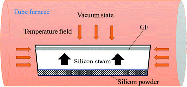
Porous GF was used as the precursor and also as the carbon source, and pre-grinding silicon powder was used as the silicon source. For the whole preparation process, no catalysts were used. GF was firstly ultrasonically cleaned with anhydrous ethanol. Before the synthesis process, the chamber of the vacuum tube furnace was purged with argon gas and then evacuated. Subsequently, the reaction process was completely performed under high-temperature conditions. Furthermore, the experimental temperature program was divided into three stages. In the first reaction step, the temperature was increased from room temperature to 1000 °C at a heating rate of 10 °C min−1. In the second step, the temperature was increased to a target temperature of 1450 °C at a heating rate of 5 °C min−1. In the last reaction step, the temperature was maintained at 1450 °C for 3 h followed by natural cooling to room temperature. Finally, the reaction was completed, a scaffold (named as S1) loaded with a large quantity of nanofibers was synthesized (the schematic diagram of the experimental setup of the synthesis process is shown in Fig. 1).2.3 Preparation of CPCM
First, GF and S1 were placed into a beaker together with solid PA, and the beaker was put into a vacuum drying oven and evacuated, followed by vacuum impregnation at a temperature of 80 °C for 3 h. At last, the beaker was removed and the excess PA on the surface was repeatedly removed with filter paper, resulting in PA/GF and PA/S1 composites of the control group, named as PA@GF and PA@S1, respectively.2.4 Characterization
The surface morphologies and chemical composition of the precursor GF and the prepared composites were observed by scanning electron microscopy (SEM) and energy dispersive X-ray spectroscopy (EDS). Moreover, the chemical compatibility of the materials was studied by X-ray diffraction (XRD) and Fourier transform infrared absorption spectroscopy (FT-IR). The thermal properties of PA and the CPCMs were investigated by differential scanning calorimetry (DSC), and PA and the CPCMs were heated from 0 to 100 °C at a heating rate of 5 °C min−1, followed by cooling to 0 °C to complete a temperature cycle. The thermal stabilities of PA and the CPCMs were measured by thermo-gravimetric analysis (TG) under a protective atmosphere of nitrogen flow, and the temperature was increased from 0 °C to the target temperature of 600 °C at a heating rate of 10 °C min−1. Moreover, the thermal conductivity coefficients and thermal transfer rates of the samples were measured using a thermal conductivity tester and an infrared camera, respectively.3. Results and discussion
3.1 Preparation and characterization of the supporting scaffold
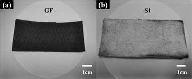
Fig. 2(a) shows a digital photograph of the raw material GF, revealing industrially produced fine graphite fibers (GFs) comparable with fabric on a macroscopic level. As shown in Fig. 2(b), the felt was coated with white fluff after the vapor–solid reaction,28,33,34 which was supposed to be SiCNFs.Moreover, the specific microscopic composition of the GF and S1 was observed by SEM. Before the vapor–solid reaction, the GF was composed of fine graphite fiber (∼8 μm) woven into nets (Fig. 3). Both on the surface (Fig. 3(a) and (b)) and in the bulk (Fig. 3(c)), the fibers overlapped each other forming a three-dimensional porous structure, which can store PCMs. In particular, the large inherent void contained in the GF (yellow circle in Fig. 3(b)). It has been reported30,31,35,36 that the heat transfer process of PCMs depends heavily on the phonon transfer, and all kinds of interactions may affect the heat transfer rate. According to the phonon transfer parameters, it is necessary to form a nanomaterial structure with continuous thermal conductivity in the scaffold of the PCM to improve the thermal conductivity of the CPCM. Therefore, in this work, the large voids contained in pristine GF were most likely to be the dominant thermal resistance in this heat transfer process. This assumption has been verified in the following.
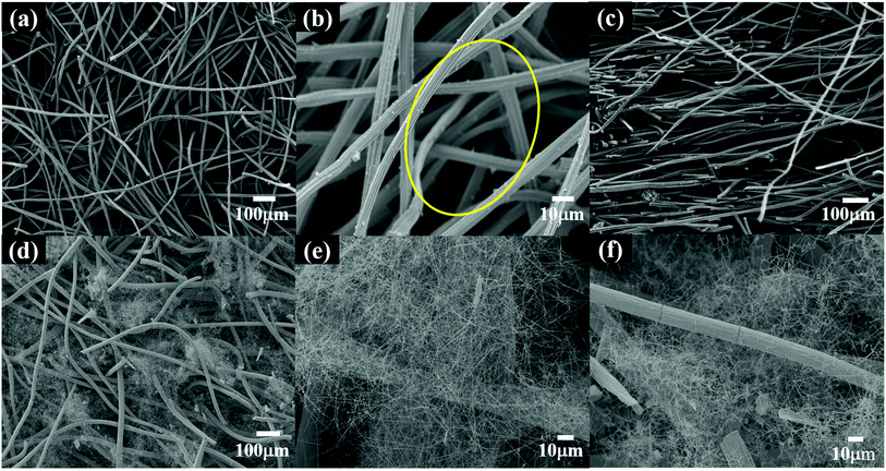 | ||
| Fig. 3 SEM images of the carbon support; (a and b) and (d and e) are the surface images of GF and S1, respectively; (c) and (f) are the bulk images of GF and S1, respectively. | ||
The images in Fig. 3(d)–(f) clearly showed that the fibers covered the surface of the GF and filled the GF inside. Compared with pristine GF, after surface treatment, the SEM images of the S1 surface and the bulk S1 showed that the large voids of GF were uniformly filled with nanofibers. In addition, the fibers were much more tenuous than the GFs, and the GFs were almost unaffected by the microstructure.
In this study, no catalysts were used during the scaffold preparing process, and reaction conditions were vacuum. Thus, the SiCNFs should be growth through a vapor–solid (V–S) mechanism. The formation mechanism of SiCNFs has been proposed in the previous reported.37–39 Combined mechanism with experimental results, the V–S formation process could be discussed by Fig. 4. As shown in Fig. 4(a), the EDS analysis of SiCNFs has proved the elements contained in the products are only C, Si and O. In addition, the XRD pattern in Fig. 4(b) also proved the reaction products are SiCNFs. In this system, shown in Fig. 4(c) and (b), the primary sources of oxygen are the oxidation layer of the silica powder, the oxidation of the silicon powder may be introduced during the grinding process, the weighing process, and the residual of air inside the porous GF. So, oxygen will directly reaction with the GF to form CO vapor when the temperature gradually rose.
| 2C(s) + O2(g) → 2CO(g) | (1) |
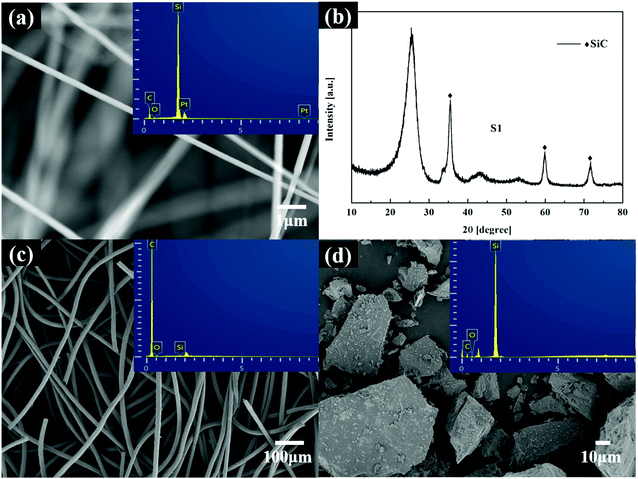 | ||
| Fig. 4 SEM and EDS patterns of the SiCNFs (a); XRD pattern of S1 (b); SEM and EDS patterns of GF (c), SEM and EDS patterns silicon powder (d), respectively. | ||
During the process, SiO vapor comes from the reaction of silicon with its natural oxide silica at high temperatures according to the reaction (2).
| Si(s) + SiO2(s) → 2SiO(g) | (2) |
According to the reaction (3) and (4), the SiCNFs growth through a vapor–solid (V–S) mechanism.
| SiO(g) + 2C(s) → SiC(s) + CO(g) | (3) |
| SiO(g) + 3CO(g) → SiC(s) + 2CO2(g) | (4) |
| CO2(g) + C(s) → 2CO(g) | (5) |
It is noteworthy that the carbon dioxide produced in the process of the reaction (5), in which the CO vapor is again reduced by the carbon source to obtain CO2 gas. Therefore, based on these reactions above, large quantities SiCNFs were generated in GF.
3.2 Preparation and characterization of CPCM
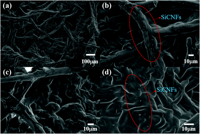
Compared with an empty scaffold, the SEM images of PA@S1 in Fig. 5 clearly showed abundant nanofibers as well as incorporated PA. The incorporation of PA was performed by vacuum impregnation. Moreover, the morphologies of the CPCM was observed from different angles, confirming that PA was uniformly distributed in S1. The surface images of PA@S1 in Fig. 5(a) and (b) revealed that the large voids and SiCNFs on the surface of the scaffold were completely wrapped by PA. In addition, the CPCM has a similar cross-linked network, which provides efficient heat transfer channels and helps CPCM to maintain shape stability.32,33,36 SEM images of the internal structure of PA@S1 are shown in Fig. 5(c) and (d), revealing a porous structure between the scaffold and the growing SiCNFs filled with PA. The SiCNFs were completely encapsulated in PA due to fibers with strong surface tension and capillary force.33 As shown in the circled places in Fig. 5(b) and (d), the obtained SiCNFs are significantly different from the GFs scale, which has shown protruding point on the surface. In addition, SiCNFs with excellent heat transfer properties are utilized as scaffold filler, enabling the formation of a complete network structure with thermal conductivity between the scaffold and the PCM due to interfacial interaction. As a result, the thermal resistance of the voids in the CPCM was reduced, which significantly improved the thermal response of the CPCM.3.3 Thermal properties of CPCM
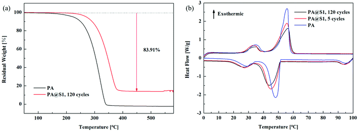
Thermal stability and thermal cycling are highly important parameters for practical applications of CPCMs. The weight loss was analyzed by thermogravimetry to evaluate the thermal stability of PA and PA@S1, as shown in Fig. 6(a). Compared with PA@S1, the pure PA residual solid content approached zero at approximately 340 °C, and the weight loss rate was higher. Furthermore, the amount of pre-synthesized CPCM decreased over multiple thermal cycles of PA@S1, and this weight loss was completed at approximately 380 °C. Moreover, the rate of weight loss of PA@S1 was lower than that of pure PA. Comprehensive analysis demonstrated improved thermal stabilities of the CPCM.33,40 In addition to this, the CPCM experienced a mass loss of up to 83.91%, which was mainly attributed to PA. Therefore, this mass loss is in good agreement with the actual loadings that were previously calculated.Apart from stabilization, DSC was performed to evaluate the thermal properties of the prepared PA@S1 and PA, and the results are shown in Fig. 6(b). Moreover, the phase change parameters of the CPCM and PA are summarized in Table 1 (the data are presented as the average of three values). The curves of pure PA and PA@S1 in Fig. 6(b) exhibit two pairs of phase change peaks: The pair of peaks near the low-temperature region was attributed to the solid–solid phase transition, while the pair of peaks near the higher temperature region was ascribed to the solid–liquid phase transition.32,41 Moreover, compared with PA, the phase transitions of the prepared PA@S1 occurred at a lower temperature due to their higher conductivity. The DSC data of PA@S1 and PA are shown in Table 1. Owing to the higher thermal conductivity of PA@S1, the energy is both stored and released faster, and this acceleration is proportional to the phase transition rate. Table 1 shows that the onset melting temperature and the onset solidification temperature of the PA@S1 were lower than those of pure PA, and similar results have been reported in literature.41 Moreover, the thermal reliability of CPCM was investigated by a couple of thermal cycling tests. Furthermore, no visible transformation was observed in the DSC curves of PA@S1 after 120 thermal cycles, demonstrating good recyclability and suitability for repeated use. In addition, the enthalpy of PA@S1 was lower than that of pure PA due to the introduction of the scaffold.42 However, the thermal properties of the CPCM in this study were high compared with other reported values.18,33,35,43–48 The comparison of the thermal properties between PA@S1 and previous reported CPCM are summarized in Table 2.
| Samples | Cycle times | Melting process | Solidification process | ||||||
|---|---|---|---|---|---|---|---|---|---|
| Tmo (°C) | Tme (°C) | Tmp (°C) | ΔHm (J g−1) | Tso (°C) | Tse (°C) | Tsp (°C) | ΔHs (J g−1) | ||
| PA | 5 | 20.1 | 51.2 | 32.3 | 214.4 | 28.1 | 57.3 | 55.8 | 210.6 |
| PA@S1 | 5 | 18.8 | 51.2 | 45.0 | 199.1 | 26.3 | 58.2 | 55.8 | 194.3 |
| PA@S1 | 120 | 18.2 | 51.0 | 43.9 | 180.5 | 26.1 | 58.9 | 56.3 | 176.4 |
| CPCM | ΔHm (J g−1) | ΔHs (J g−1) | Thermal conductivity (W m−1 K−1) | Ref. |
|---|---|---|---|---|
| Paraffin/carbon foam | 174.3 | 151.4 | 0.339 | 18 |
| Stearic acid/silicon carbide nanofiber | 155.9 | 155.8 | 0.432 | 33 |
| Paraffin/polyaniline@cobalt | 170.56 | — | 0.233 | 35 |
| Paraffin/expanded graphite/polypropylene | 110.24 | 113.79 | 0.35 | 43 |
| Paraffin@SiO2/PUPEG/BN | 112.23 | — | 0.675 | 45 |
| Paraffin/sepiolite | 60.12 | 57.09 | — | 46 |
| Paraffin/Ti3C2Tx Mxene@Gelatin | — | — | 0.919 | 48 |
| Polyethylene glycol/carbon foam | — | — | 0.68 | 47 |
| Paraffin/single-wall carbon nanotubes | — | — | 0.710 | 49 |
| PA@S1 | 180.5 | 176.4 | 1.29 | This work |
3.4 Chemical stability analysis
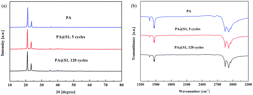
Furthermore, X-ray diffraction (XRD) and Fourier transform infrared absorption spectroscopy (FT-IR) analysis confirmed the successful synthesis of PA and PA@S1. The diffraction patterns of PA and PA@S1 are shown in Fig. 7(a). The diffraction pattern of PA exhibited two characteristic peaks located at 21.5° and 24.1°, which indicated that PA was crystallized. The characteristic peak at 26° was identified as the main peak of graphite. S1 is mainly composed of graphite, and the other peaks located at 36°, 60°, and 72° were identified as the characteristic peaks of SiC.29,33,41 Therefore, these results confirmed the above SEM results. Moreover, to evaluate if PA was uniformly embedded in S1, the XRD patterns of PA@S1 were recorded before and after 120 cycles. After 120 cycles, no new peaks have appeared, and the PA@S1 pattern was similar to that of pure PA, only showing the characteristic peaks of PA at 21.5° and 24.1°.30,41 Therefore, this analysis demonstrated that PA was only physically adsorbed on S1.In addition to XRD, PA and PA@S1 were characterized by FT-IR analysis, as shown in Fig. 7(b). The FT-IR spectrum of PA exhibited two absorption bands at 1378 and 1464 cm−1, which were assigned to the in-plane bending vibration of C–H. In addition, it exhibited absorption bands at 2847 and 2916 cm−1, which corresponded to asymmetric and symmetric stretching vibrations of aliphatic C–H, respectively.42,46 PA@S1 spectra were recorded before and after multiple cycles and only exhibited the characteristic absorption bands of PA at 1378, 1464, 2847, and 2916 cm−1. In conclusion, the diffraction analysis is in accordance with the XRD results. Accordingly, it is concluded that no chemical reaction occurred between S1 and PA. Moreover, the results also indicated that the prepared CPCM was chemically stable.
3.5 Thermal conductivity
Apart from the thermal performance, the thermal conductivity of the CPCM (PA@GF or PA@S1) is also considered vitally important for the investigation of the energy storage and release performance. The thermal conductivity values of all samples are shown in Fig. 8(a), revealing that all CPCMs exhibited significantly improved thermal conductivities compared with PA. Furthermore, although single GFs have been demonstrated to have an ultra-high thermal conductivity of 372.4 W m−1 K−1,50 the thermal conductivity of PA@GF using pristine GF as a scaffold was significantly lower than that of CPCM obtained after infiltration with S1. Considering the assumptions previously made in the SEM section, this may be due to the large voids inside the GF with randomly arranged fibers, which are a major obstacle29,33,42 in the heat transfer process and reduce the thermal conductivity of the composite. Notably, the scaffold loaded with SiCNFs further verified our previous assumptions that the thermal conductivity of PA@S1 (1.29 W m−1 K−1) was improved by 5.16 times compared with that of pure PA (0.25 W m−1 K−1) due to the reduced thermal resistance in the heat transfer process. The thermal conductivity of PA@S1 is relatively high compared with those of reported CPCMs.18,43–45,49,51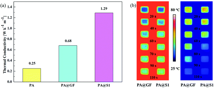 | ||
| Fig. 8 Thermal conductivity of PA and the CPCM (a) and thermal images were obtained by the infrared camera during heating and cooling processes of the CPCM (b). | ||
The thermal conductivity affects the efficiency of energy storage and the release of the CPCM. Therefore, the heat transfer sensitivity of the CPCM was observed through an infrared camera (Fig. 8(b)). Compared with PA@GF, the temperature change of PA@S1 was faster and more significant. Furthermore, the images showed that, during the melting and solidification processes, the color change of the PA@S1 was more dramatic, showing a significant effect of thermal conductivity on the heat transfer rate.
3.6 Photo-thermal energy conversion
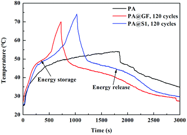
Furthermore, the thermal energy storage of PA and CPCM can be observed by photo-thermal conversion. Fig. 9 shows the temperature–time curves of PA and the CPCM under the same conditions. The results were showed that the temperature–time curve of PA did not display a plateau. However, the temperature–time curve of CPCM present the plateau due to the phase change of PA. Furthermore, compared with PA@GF, the scaffold and SiCNFs of PA@S1 can better absorb solar radiation, followed by the energy conversion and storage. Therefore, thermal energy storage and release can be achieved during the PCMs changed from a solid state to a liquid state (or liquid to solid). In addition, the temperature–time curve of CPCM showed two plateaus during the phase change.52 Upon solar radiation, CPCM absorbed solar energy in the PCMs melting process. When removed the radiation source, CPCM showed the PCMs cooling process. With these characteristics, PCMs have the great potential for energy storage materials.30 Moreover, the photo-thermal conversion efficiency η (ref. 40) can be calculated by eqn (6), where m is the mass of the sample, ΔH is the phase change enthalpy of the sample obtained by DSC, A is the area of the sample irradiated by light, P is the power of the light source (W cm−2), and t is the time from the beginning to the end of the phase change process.
 | (6) |
In addition to the aforementioned features, under the solar radiation, the photo-thermal conversion efficiency of CPCM containing with PA@GF and PA@S1 were calculated to be 70.50% and 83.72%, respectively. In this study, a scaffold with abundant SiCNFs of a network was devised with black appearance to provide a conductive pathway for heat transfer. The PA@S1 as a promising candidate was prepared for solar or thermal energy storages applications52 with wide application prospects.
3.7 Leakage experiments and shape design of CPCM
Reducing leakage during cycling of organic PCMs is important for their practical application in production. Fig. 10(a) and (b) shows optical photographs of the here designed leakage test. These photographs show that PA was completely melted, and the filter paper was covered by liquid PA after heating at 80 °C for 1 h. Furthermore, PA@S1 maintained its shape after continuous heating. Moreover, no significant percolation of liquid PA from the surface was observed. This indicates that the PA@S1 can maintain its shape in this working temperature range and does not collapse after multiple thermal cycles, providing the requirements for multiple reuses in practical applications. | ||
| Fig. 10 Shape stability analysis and leakage test of PA and PA@S1 (a and b) and the shape design of the CPCM (c). | ||
In addition to micro-structurally devised scaffolds, the scaffold has a flexible shape design (Fig. 10(c)). In this regard, samples were flexible in the design of shapes with different dimensions during utilization. Thus, the easy design based on the shape feature of the here prepared PA@S1 presented an advantage for application in the construction field.53 Consequently, the prepared PA@S1 have overcome the shape and size limitations in production applications.
4. Conclusions
The SiC nanofibers/graphite felt/paraffin composite phase change material with high-energy storage density (180.5 and 176.4 J g−1), excellent thermal conductivity (1.29 W m−1 K−1), good shape stability and chemical stability was prepared by a low-cost and short process. In addition, the material exhibits the advantages of high photo-thermal conversion efficiency (83.72%) and outstanding flexibility in the sample appearance design. These characteristics are great advantages for solar energy storage and buildings, promising a wide range of practical applications in the future.Conflicts of interest
There are no conflicts of interest to declare.Acknowledgements
This work is supported by the National Natural Science Foundation of China (Grant no. 51802172) and the Natural Science Foundation of Qinghai Province (Grant no. 2021-ZJ-713).References
- Z. Yinxu, Z. Xuelai and H. Weisan, Review of preparation technologies of organic composite phase change materials in energy storage, J. Mol. Liq., 2021, 336, 115923 CrossRef.
- W. G. Ernst, Overview of naturally occurring Earth materials and human health concerns, J. Asian Earth Sci, 2012, 59, 108–126 CrossRef.
- P. Cristina and L. F. Cabeza, Thermal energy storage with phase change materials in solar power plants. Economic analysis, J. Energy Storage, 2021, 43, 103184 CrossRef.
- C. Gao, X. Min, M. Fang, T. Tao and X. Zheng, et al., Innovative Materials Science via Machine Learning, Adv. Funct. Mater., 2021, 1–14 Search PubMed.
- P. Tan, P. Lindberg, K. Eichler, P. Löveryd and P. Johansson, et al., Thermal energy storage using phase change materials: Techno-economic evaluation of a cold storage installation in an office building, Appl. Energy, 2020, 276, 115433 CrossRef CAS.
- D. Kun, C. John, E. Philip and W. Yupeng, A state-of-the-art review of the application of Phase Change Materials (PCM) in Mobilized-Thermal Energy Storage (M-TES) for recovering low-temperature Industrial Waste Heat (IWH) for distributed heat supply, Renewable Energy, 2020, 168, 1040–1057 Search PubMed.
- M. M. Chen and F. Q. Zhao, Research and Application of Phase Change Energy Storage Technology in Construction and Buildings Materials, Adv. Mater. Res., 2014, 3604, 377–381 Search PubMed.
- A. A. M. Omara, Phase change materials for waste heat recovery in internal combustion engines: A review, J. Energy Storage, 2021, 44, 103421 CrossRef.
- G. Cheng, X. Wang and Y. He, 3D graphene paraffin composites based on sponge skeleton for photo thermal conversion and energy storage, Appl. Therm. Eng., 2020, 178, 115560 CrossRef CAS.
- K. Pielichowska and K. Pielichowski, Phase change materials for thermal energy storage, Prog. Mater. Sci., 2014, 65, 67–123 CrossRef CAS.
- V. V. Tyag, K. Chopra, R. K. Sharma, A. K. Pandey and S. K. Tyagi, et al., A comprehensive review on phase change materials for heat storage applications: Development, characterization, thermal and chemical stability, Sol. Energy Mater. Sol. Cells, 2022, 234, 111392 CrossRef.
- N. Şahan, M. Fois and H. Paksoy, Improving thermal conductivity phase change materials-A study of paraffin nanomagnetite composites, Sol. Energy Mater. Sol. Cells, 2015, 137, 61–67 CrossRef.
- X. Guo, Y. Huang and J. Cao, Performance of a thermal energy storage composite by incorporating diatomite stabilized paraffin as phase change material, Energy Build., 2018, 158, 1257–1265 CrossRef.
- X. Li, J. G. Sanjayan and J. L. Wilson, Fabrication and stability of form-stable diatomite/paraffin phase change material composites, Energy Build., 2014, 76, 284–294 CrossRef.
- Z. Liu, C. Zang, Z. Ju, D. Hu and Y. Zhang, et al., Consistent preparation, chemical stability and thermal properties of a shape-stabilized porous carbon/paraffin phase change materials, J. Cleaner Prod., 2020, 247, 119565 CrossRef CAS.
- Z. Sun, Y. Zhang, S. Zheng, Y. Park and R. L. Frost, Preparation and thermal energy storage properties of paraffin/calcined diatomite composites as form-stable phase change materials, Thermochim. Acta, 2013, 558, 16–21 CrossRef CAS.
- B. Shengyou, W. Qiuping, C. Jun, L. Haichao and M. Li, et al., Hydrophilic modification of carbon nanotube to prepare a novel porous copper network-carbon nanotube/erythritol composite phase change material, Compos. Interfaces, 2021, 28, 175–189 CrossRef.
- S. Tengteng, Z. Xiaoguang, Q. Jiaxin, W. Xiaowen and C. Guo, et al., Preparation and characterization of composite phase change materials based on paraffin and carbon foams derived from starch, Polymer, 2021, 212, 123143 CrossRef.
- M. M. Kenisarin and K. M. Kenisarina, Form-stable phase change materials for thermal energy storage, Renewable Sustainable Energy Rev., 2012, 16, 1999–2040 CrossRef CAS.
- R. J. Warzoha and A. S. Fleischer, Improved heat recovery from paraffin-based phase change materials due to the presence of percolating graphene networks, Int. J. Heat Mass Transfer, 2014, 79, 314–323 CrossRef CAS.
- L.-d. Zhang, X. Chen, Y.-t. Wu, Y.-w. Lu and C.-f. Ma, Effect of nanoparticle dispersion on enhancing the specific heat capacity of quaternary nitrate for solar thermal energy storage application, Sol. Energy Mater. Sol. Cells, 2016, 157, 808–813 CrossRef CAS.
- D. G. Atinafu, W. Dong, J. Wang, X. Huang, J. Wang, H. Gao and G. Wang, Synthesis and Characterization of Paraffin/Metal Organic Gel Derived Porous Carbon/Boron Nitride Composite Phase Change Materials for Thermal Energy Storage, Eur. J. Inorg. Chem., 2018, 2018, 5167–5175 CrossRef CAS.
- W. Shaofei, Y. Ting, K. Zihan and P. Weiguo, Corrigendum to: “Thermal conductivity enhancement on phase change materials for thermal energy storage: A review”, Energy Storage Mater., 2020, 33, 503 CrossRef.
- Z. Xiao, W. Qi, K. Shouguo, L. Jinlai and J. Xilai, Coal-based ultrathin-wall graphitic porous carbon for high-performance form-stable phase change materials with enhanced thermal conductivity, Chem. Eng. J., 2020, 395, 125112 CrossRef.
- L. Zhang, K. Zhou, Q. Wei, L. Ma and W. Ye, et al., Thermal conductivity enhancement of phase change materials with 3D porous diamond foam for thermal energy storage, Appl. Energy, 2019, 233–234, 208–219 CrossRef CAS.
- A. Karaipekli, A. Sarı and K. Kaygusuz, Thermal conductivity improvement of stearic acid using expanded graphite and carbon fiber for energy storage applications, Renewable Energy, 2006, 32, 2201–2210 CrossRef.
- N. Sheng, R. Zhu, T. Nomura, Z. Rao and C. Zhu, et al., Anisotropically enhanced heat transfer properties of phase change material reinforced by graphene-wrapped carbon fibers, Sol. Energy Mater. Sol. Cells, 2020, 206, 110280 CrossRef CAS.
- H. J. Hwang, K.-J. Lee, Y.-T. An, B.-H. Choi and W.-S. Seo, Synthesis of β-silicon carbide nanofiber from an exfoliated graphite and amorphous silica, Mater. Chem. Phys., 2012, 134, 13–15 CrossRef CAS.
- Z. Zhenghe, T. Jing, C. Lisheng and Y. Weimin, In-situ growth of silicon carbide nanofibers on carbon fabric as robust supercapacitor electrode, Ceram. Int., 2021, 47, 24652–24662 CrossRef.
- X. Zhu, L. Han, F. Yang, J. Jiang and X. Jia, Lightweight mesoporous carbon fibers with interconnected graphitic walls for supports of form-stable phase change materials with enhanced thermal conductivity, Sol. Energy Mater. Sol. Cells, 2020, 208, 285–290 CrossRef.
- J. Chen, P. Xiao and X. Xiong, The mechanical properties and thermal conductivity of carbon/carbon composites with the fiber/matrix interface modified by silicon carbide nanofibers, Mater. Des., 2015, 84, 285–290 CrossRef CAS.
- W.-m. Guan, J.-h. Li, T.-t. Qian, X. Wang and Y. Deng, Preparation of paraffin/expanded vermiculite with enhanced thermal conductivity by implanting network carbon in vermiculite layers, Chem. Eng. J., 2015, 277, 56–63 CrossRef CAS.
- C. Li, X. Zhao and J. Chen, Diversiform microstructure silicon carbides stabilized stearic acid as composite phase change materials, Sol. Energy, 2020, 201, 92–101 CrossRef CAS.
- J. Liang, W. Guo, J. Liu, H. Qin and P. Gao, et al., Synthesis of in-situ SiC nanowires by self-assembly nanoparticles on carbon fibers and their photoluminescence properties, J. Alloys Compd., 2019, 797, 101–109 CrossRef CAS.
- B. Kalidasan, A. K. Pandey, S. Syed, G. Mathew and S. Kamal, et al., Synthesis and characterization of conducting Polyaniline@cobalt-Paraffin wax nanocomposite as nano-phase change material: Enhanced thermophysical properties, Renewable Energy, 2021, 173, 1057–1069 CrossRef.
- L. Maohua, L. Linhong, H. Xiao, Q. Yue and S. Guichen, et al., Synergistic Effect ofCarbon Fiber and Graphite on Reducing Thermal Resistance of Thermal Interface Materials, Compos. Sci. Technol., 2021, 212, 108883 CrossRef.
- H. Liu, Z. Huang and J. Huang, Thermal evaporation synthesis of SiC/SiOx nanochain heterojunctions and their photoluminescence properties, J. Mater. Chem. C, 2014, 2, 7761–7767 RSC.
- Z. Huang, H. Liu, K. Chen, M. Fang and J. Huang, et al., Synthesis and formation mechanism of twinned SiC nanowires made by a catalyst-free thermal chemical vapour deposition method, RSC Adv., 2014, 18360–18364 RSC.
- H. Liu, Z. Huang, M. Fang, Y.-g. Liu and X. Wu, Preparation and growth mechanism of β-SiC nanowires by using a simplified thermal evaporation method, J. Cryst. Growth, 2015, 419, 20–24 CrossRef CAS.
- W. Aftab, A. Mahmood, W. Guo, M. Yousaf and H. Tabassum, et al., Polyurethane-based flexible and conductive phase change composites for energy conversion and storage, Energy Storage Mater., 2019, 20, 401–409 CrossRef.
- S. Zhenghui, K. Soojin, L. H. Lae, T. Martti and O. Kyudeok, Cellulose nanofibril/carbon nanotube composite foam-stabilized paraffin phase change material for thermal energy storage and conversion, Carbohydr. Polym., 2021, 273, 118585 CrossRef PubMed.
- C. Liu and Z. Dong, Application potential of graphene aerogel in paraffin phase change composites: Experimental study and guidance based on numerical simulation, Sol. Energy Mater. Sol. Cells, 2021, 223, 110949 CrossRef.
- L. Dajun, X. Li, S. Xin, X. Lan and Z. Dengfeng, et al., Phase-change smart lines based on paraffin-expanded graphite/polypropylene hollow fiber membrane composite phase change materials for heat storage, Energy, 2020, 197, 117252 CrossRef.
- J. Su-Gwang, W. Seunghwan, C. S. Jin and K. Sumin, Energy performance evaluation of heat storage of calcium sulfate hemihydrate composite with fine aggregate based on paraffinic phase change material, J. Build. Eng., 2021, 42, 103075 CrossRef.
- H. Xuquan, Z. Ling and L. Chunzhong, PEG-based polyurethane/Paraffin@SiO2/Boron nitride phase change composite with efficient thermal conductive pathways and superior mechanical property, Compos. Commun., 2021, 100609 Search PubMed.
- L. Yue, X. Suya, H. Jintao, Z. Feng and L. Chongchong, et al., Preparation, characterization and performance of paraffin/sepiolite composites as novel shape-stabilized phase change materials for thermal energy storage, Sol. Energy Mater. Sol. Cells, 2021, 231, 111300 CrossRef.
- L. Fankai, Z. Xiaoguang, L. Xianjie, X. Yunfei and S. Zhenhua, et al., Polyethylene glycol/modified carbon foam composites for efficient light-thermal conversion and storage, Polymer, 2021, 228, 123894 CrossRef.
- X. Liu, F. Lin, X. Zhang, M. Liu and Z. Sun, et al., Paraffin/Ti3C2Tx Mxene@Gelatin Aerogels Composite Phase-Change Materials with High Solar-Thermal Conversion Efficiency and Enhanced Thermal Conductivity for Thermal Energy Storage, Energy Fuels, 2021, 35, 2805–2814 CrossRef CAS.
- A. W. Kuziel, D. Grzegorz, T. Roman, R. G. Jędrysiak and K. Anna, et al., Ultra-long carbon nanotube-paraffin composites of record thermal conductivity and high phase change enthalpy among paraffin-based heat storage materials, J. Energy Storage, 2021, 36, 102396 CrossRef.
- J. Liu, Y. Hu and X. Zhang, Characterization of thermal transport and laser absorption properties of an individual graphitized carbon fiber by applying Raman thermography, Thermochim. Acta, 2018, 663, 183–188 CrossRef CAS.
- X. Fang, L.-W. Fan, Q. Ding, X.-L. Yao and Y.-Y. Wu, et al., Thermal energy storage performance of paraffin-based composite phase change materials filled with hexagonal boron nitride nanosheets, Energy Convers. Manage., 2014, 80, 103–109 CrossRef CAS.
- S. T. Latibari and S. M. Sadrameli, Carbon based material included-shaped stabilized phase change materials for sunlight-driven energy conversion and storage: An extensive review, Sol. Energy, 2018, 170, 1130–1161 CrossRef.
- V. V. Tyagi, K Chopra, B. Kalidasan, C. Aditya and U. Stritih, et al., Phase change material based advance solar thermal energy storage systems for building heating and cooling applications: A prospective research approach, Sustainable Energy Technologies and Assessments, 2021, 47, 101318 CrossRef.
| This journal is © The Royal Society of Chemistry 2022 |

