DOI:
10.1039/D1RA08117A
(Paper)
RSC Adv., 2022,
12, 5466-5482
Silver cluster doped graphyne (GY) with outstanding non-linear optical properties†
Received
5th November 2021
, Accepted 20th January 2022
First published on 15th February 2022
Abstract
This research study addresses the computational simulations of optical and nonlinear optical (NLO) characteristics of silver (Ag) cluster doped graphyne (GY) complexes. By precisely following DFT and TD-DFT hypothetical computations, in-depth characterization of GY@Agcenter, GY@Agside, GY@2Agperpendicular, GY@2Agabove, and GY@3Agcenter is accomplished using CAM-B3LYP/LANL2DZ while the CAM-B3LYP/mixed basis set is used for study of 2GY@Agcenter, 2GY@Agside, 2GY@2Agperpendicular, 2GY@2Agabove, and 2GY@3Agcenter. The effects of various graphyne surface based complexes on hyperpolarizabilities, frontier molecular orbitals (FMOs), density of states (DOS), absorption maximum (λmax), binding energy (Eb), dipole moment (μ), electron density distribution map (EDDM), transition density matrix (TDM), electrostatic potential (ESP), vertical ionization energy (EVI) and electrical conductivity (σ) have been investigated. Infrared (IR), non-covalent interaction (NCI) analysis accompanied by isosurface are performed to study the vibrational frequencies and type of interaction. Doping strategies in all complexes impressively reformed charge transfer characteristics such as narrowing band gap (Eg) in the range of 2.58–4.73 eV and enhanced λmax lying in the range of 368–536 nm as compared to pure GY with 5.78 eV Eg and 265 nm λmax for (GY@Agcenter–GY@3Agcenter). In the case of (2GY@Agcenter–2GY@3Agcenter), when compared to 2GY with 5.58 eV Eg and 275 nm absorption, maximum doping techniques have more effectively modified λmax in the region of 400–548 nm and Eg, which is in the order of 2.55–4.62 eV. GY@3Agcenter and 2GY@3Agcenter reflected a noteworthy increment in linear polarizability αO (436.90 au) and (586 au) and the first hyperpolarizability βO (5048.77 au) and (17![[thin space (1/6-em)]](https://www.rsc.org/images/entities/char_2009.gif) 270 au) because of their lowest excitation energy (ΔE) when studied in comparison with GY (αO = 281.54 and βO = 0.21 au) and 2GY surface (αO = 416 and βO = 0.06 au). Focusing on harmony between the tiny Ag clusters and graphyne surface as well as their influences on NLO properties, graphyne doping using its two-unit cells (2GY) is found to be expedient for the development of future nanoscale devices.
270 au) because of their lowest excitation energy (ΔE) when studied in comparison with GY (αO = 281.54 and βO = 0.21 au) and 2GY surface (αO = 416 and βO = 0.06 au). Focusing on harmony between the tiny Ag clusters and graphyne surface as well as their influences on NLO properties, graphyne doping using its two-unit cells (2GY) is found to be expedient for the development of future nanoscale devices.
1. Introduction
With the breakthroughs of the ruby laser in 1960 and the second harmonic generation (SHG) in 1961, Franklin and his associates centralized their study on the non-linear optical (NLO) field, and this field turned into a progressive and distinctive discipline in interdisciplinary research.1 NLO materials are turning out to be extremely prevalent on account of their probable uses in light emitters,2 photonics,3 optical switching4 and holographic imaging5 as well as electro-opto modulations.6 For thirty years, NLO processes were mostly overlooked after being hypothesized in the 1930s. Recent hi-tech implementations encompass luminous materials gyroscopes,7 frequency mixing, biosensor scanners,8 SHG, and optical switching.9 The computation of a substantial amount of data produced from diverse origins demands influential and proficient computers. Optical technology provides various methodologies of expanding information handling capabilities.10 Increasing computing demands can be executed by NLO materials, for this reason, numerous modern organic and inorganic NLO active materials have been developed.11
Organic molecules based on NLO materials such as dibenzoboroles,12 benzimidazoles, and chalcogens have been forefront in designing such materials due to their increased value of NLO coefficient, structural and electrical properties.13 Because of desirable characteristics like greater thermal stability, facile synthesis, inexpensive, strength, and good transparency, inorganic molecules i.e., phosphides and nitrides based NLO materials with considerable first or second hyperpolarizabilities had gained considerable research interest.14 Significant variety of ordinary methodologies namely diradical character,15 donor–acceptor π bridge system,16 excess electron model,17 and octupolar molecules18 have been introduced to acquire ultrarapid high response NLO materials with exceptional hyperpolarizability.
GY,19 as a novel non-natural carbon allotrope initially suggested by Baughman in 1987 (ref. 20) made up of sp-hybridized (ethynyl units) and sp2-hybridized (benzene rings) carbon21 comparable to graphite/graphene (GR), has drawn the interest of researchers owing to its fascinating electrochemical, optoelectronic, and structural characteristics, as well as prospective microelectronic and power storage applications.22–25 However, as far as we could possibly know the effect of doping of silver (Ag) cluster on the external layer of GY has yet to be accounted for. In view of this, the goal of this investigation is to determine the consequences of Ag cluster doping with GY on NLO and optoelectronic properties.
In this research project motivated by systematic exploration of graphyne, we performed simulations using one-unit celled graphyne as well as two-unit celled graphyne named as GY and 2GY respectively, five different Ag clusters doped with GY surface namely GY@Agcenter, GY@Agside, GY@2Agperpendicular, GY@2Agabove, and GY@3Agcenter are studied under model 1, each varying in orientation and number of dopant (Ag) on the surface (GY). Additionally, doping of Ag clusters on 2GY generated five different doped complexes namely 2GY@Agcenter, 2GY@Agside, 2GY@2Agperpendicular, 2GY@2Agabove, and 2GY@3Agcenter which are studied under model 2.
GY@Agcenter and 2GY@Agcenter possess one Ag atom doped on GY and 2GY at their center. GY@Agside and 2GY@Agside had one Ag atom doped at the sides of their surfaces. GY@2Agperpendicular, as well as 2GY@2Agperpendicular contain two Ag atoms doped in a perpendicular direction in the central cavity of GY and 2GY. GY@2Agabove and 2GY@2Agabove retain two Ag atoms just above the GY as well as 2GY surface. While GY@3Agcenter and 2GY@3Agcenter contain three Ag atoms in the central cavity of GY and 2GY. All of the doped complexes are found to be sufficiently stable. Fig. 1 shows a schematic diagram of model 1 and model 2.
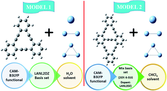 |
| | Fig. 1 Schematic diagram of model 1 as well as model 2. | |
2. Computational details
The Gaussian 09 simulation program26 has been used to perform all computations for (GY@Agcenter–2GY@3Agcenter) and GY as well as 2GY. Structures of all molecules under category of model 1 are optimized using CAM-B3LYP27 functional in association with the LANL2DZ basis set. While structures of complexes under the category of model 2 i.e. 2GY@Agcenter, 2GY@Agside, 2GY@2Agperpendicular, 2GY@2Agabove, 2GY@3Agcenter and 2GY are optimized using CAM-B3LYP/mixed basis. In mixed basis set of model 2 molecules, dopant (Ag) is optimized at LANL2DZ and 2GY surface via 6-31G basis set. To validate the type of computed geometries, frequency estimations were also conducted on the coordinates of optimized geometry. The molecular geometry, frontier molecular orbitals (FMOs), together with electrostatic potential (ESP) are extracted from optimized structures. UV-Vis spectral simulations of model 1 and model 2 are performed using time-dependent density functional theory (TD-DFT) along with their respective basis set with CAM-B3LYP functional. IEFPCM28 is employed to specifically analyse the influence of H2O and CHCl3 on absorption (λmax) of complexes of model 1 and model 2 respectively. The λmax of researched molecules is processed in gas in addition to solvent phase. The Swizard program29 has been used to compute spectral values and graphed with Origin 6.0 [22]. Interaction energies (Eint) are approximated using the following relation30 to substantiate the thermodynamic stability of our doped surfaces (GY and 2GY).| | |
Eint = Ed_nGY − (EnGY + En_Ag)
| (1) |
Here, Ed_nGY, EnGY and En_Ag are energies of doped graphene, pure graphene, and n number of silver (Ag) and graphyne unit cells respectively. Vertical ionization energy (EVI) is also evaluated using eqn (2) (ref. 31) given below| | |
EVI = Ed_nGY+ − Ed_nGY
| (2) |
Here, Ed_nGY+ and Ed_nGY represent cationic energy of Ag doped surfaces (GY and 2GY) and neutral energy of Ag doped surfaces (GY and 2GY). PyMOlyze 1.1 software32 has been used to visualize DOS files while Multiwfn 3.7 tool33 was used to determine electron densities. The same functional is also used electron density difference map (EDDM), dipole moment (μ), and infrared (IR) analysis. Hyperpolarizabilities are the most prevalent indicator of molecule's NLO response.
Through CAM-B3LYP/LANL2DZ basis set and CAM-B3LYP/mixed basis set, the αiso and αaniso (linear static polarizability), and βstatic (first hyperpolarizability) are computationally estimated using expressions9,34 given below
| |
 | (3) |
| | |
β0 = (βx2 + βy2 + βz2)
| (4) |
In equation, βx = βxxx + βxxy + βxxz, βy = βyyy + βyzz + βyxx, and βz = βzzz + βzxx + βzyy.
3. Results and discussion
3.1 Geometry optimization
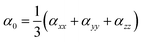
Optoelectronic characteristics are greatly influenced by molecular geometry. In model 1, CAM-B3LYP/LANL2DZ functional is used to optimize the pure GY as well as newly dopped molecules (GY@Agcenter–GY@3Agcenter). Model 2 employs CAM-B3LYP/mixed basis set to optimize the pure 2GY as well as newly dopped systems (2GY@Agcenter–2GY@3Agcenter). The front and side views of optimized frameworks of all molecules of model 1 and model 2 are shown in Fig. 2.
 |
| | Fig. 2 Framework of all optimized structures from front and top views. | |
3.2 Photophysical properties
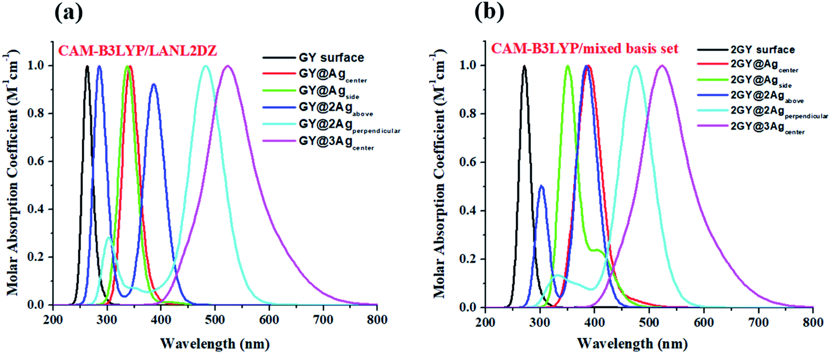
It's crucial to look at UV-visible spectra while researching electronic excitations and charge transfer. The absorption profile of model 1 having pure GY and doped complexes (GY@Agcenter–GY@3Agcenter) is computed with CAM-B3LYP/LANL2DZ functional in the gaseous phase and H2O solvent while that of model 2 via CAM-B3LYP/mixed basis set in gaseous phase and CHCl3 solvent. The absorption profile of model 1 along with model 2 illustrates that all newly doped complexes are associated with higher wavelength than the GY surface in the gaseous phase as expressed in Fig. 3. Fig. 4 revealed that the employment of solvent as well as shifting toward higher unit cells of GY is due to stabilization of π-electrons.35 GY@3Agcenter has explored the highest λmax in the gaseous phase (522 nm) together with H2O phase (536 nm) amongst all molecules of model 1 due to the presence of three atoms of Ag on the GY surface. The λmax of all complexes in solvent phase is increasing as GY< GY@Agside < GY@Agcenter < GY@2Agabove < GY@2Agperpendicular < GY@3Agcenter. Likewise, the highest λmax in the gaseous phase (538 nm) as well as in the solvent phase (548 nm) among (2GY–2GY@3Agcenter) complexes has been examined by 2GY@3Agcenter.
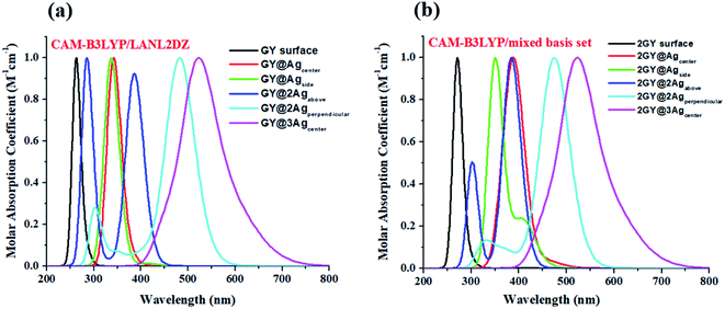 |
| | Fig. 3 UV-visible absorption graphs in gaseous phase of molecular complexes of (a) model 1 and (b) model 2. | |
 |
| | Fig. 4 UV-visible absorption graphs in solvent phase of molecular complexes of (a) model 1 and (b) model 2. | |
The band gap (Eg) together with λmax are in intense correlation. Lower Eg makes the electronic excitation feasible. Narrow Eg is often interlinked to low kinetic stability since it is energetically preferable to remove electrons from low energy HOMO or add electrons to high energy LUMO resulting in the formation of activated complexes. However, because of lower Eg, these doped systems can be regarded as n-type semiconductors.21 These doped complexes have been regarded as novel members of NLO materials. Values of λmax, excitation energy (Eopt) and oscillator strength (fOC) in both phases are summarized in Tables 1 as well as 2 respectively.
Table 1 Computed λmax, excitation energy (Eopt), highest oscillator strength fOC, major molecular transitions of molecular systems of model 1 (GY–GY@3Agcenter) and model 2 (2GY–2GY@3Agcenter) in the gaseous phase
| Molecules |
λmax (nm) |
Eopt (eV) |
fOC |
Major molecular transitions (HOMO = H, LUMO = L) |
| GY |
262 |
4.72 |
1.1619 |
H → L (69%) |
| GY@Agcenter |
342 |
3.62 |
0.0991 |
H → L (72%) |
| GY@Agside |
343 |
3.62 |
0.1043 |
H → L (90%) |
| GY@2Agperpendicular |
483 |
2.97 |
0.3980 |
H → L (66%) |
| GY@2Agabove |
386 |
3.41 |
0.5394 |
H → L (70%) |
| GY@3Agcenter |
522 |
2.37 |
0.0923 |
H → L (100%) |
| 2GY |
269 |
4.60 |
2.2631 |
H → L (66%) |
| 2GY@Agcenter |
393 |
3.15 |
0.0025 |
H → L (52%) |
| 2GY@Agside |
410 |
2.97 |
0.0031 |
H → L (58%) |
| 2GY@2Agperpendicular |
475 |
2.60 |
0.4104 |
H → L (67%) |
| 2GY@2Agabove |
385 |
3.22 |
0.5690 |
H → L (70%) |
| 2GY@3Agcenter |
538 |
2.36 |
0.0923 |
H → L (76%) |
Table 2 Computed λmax, excitation energy (Eopt), highest oscillator strength fOC, major molecular transitions of molecular systems of model 1 (GY–GY@3Agcenter) and model 2 (2GY– 2GY@3Agcenter) in the solvent phase
| Molecules |
λmax (nm) |
Eopt (eV) |
fOC |
Major molecular transitions (HOMO = H, LUMO = L) |
| GY |
265 |
4.68 |
1.1767 |
H → L (69%) |
| GY@Agcenter |
368 |
3.37 |
0.1407 |
H → L (93%) |
| GY@Agside |
362 |
3.43 |
0.1773 |
H → L (95%) |
| GY@2Agperpendicular |
421 |
2.94 |
0.4358 |
H → L (67%) |
| GY@2Agabove |
373 |
3.32 |
0.6140 |
H → L (70%) |
| GY@3Agcenter |
536 |
2.31 |
0.1283 |
H → L (100%) |
| 2GY |
275 |
4.51 |
2.5857 |
H → L (66%) |
| 2GY@Agcenter |
400 |
3.29 |
0.1376 |
H → L (82%) |
| 2GY@Agside |
400 |
3.30 |
0.0009 |
H → L (63%) |
| 2GY@2Agperpendicular |
465 |
2.75 |
0.4577 |
H → L (76%) |
| 2GY@2Agabove |
410 |
3.09 |
0.6636 |
H → L (70%) |
| 2GY@3Agcenter |
548 |
2.31 |
0.1283 |
H → L (93%) |
Results of tables confirmed that the employment of solvent has redshifted the λmax of molecules of both models. Absorption (λmax) values of studied systems such as GY, GY@Agcenter, GY@Agside, GY@3Agcenter, 2GY, GY@Agcenter, GY@3Agabove, and GY@3Agcenter are shifted to higher values in solvent. Like, λmax of pure surface GY and 2GY is 262 and 269 nm in gaseous phase; 265 and 275 nm in H2O owing to the stabilization of delocalized π-electrons.35 Excitation energies (Eopt) of all molecules are lowered in solvents showing the ease of electron excitations in solvent phase as compared to the gaseous phase i.e., Eopt of GY and 2GY is shifted from 4.72 and 4.60 eV to 4.68 and 4.51 eV. Shifting of molecular transitions to higher percentage also signifies ease of electronic excitation from HOMO to LUMO energy levels. Graphical comparative study of absorption maximum of all molecules of models 1 and 2 in gaseous and solvent phase is revealed in Fig. 5. Similarly, Fig. 6 illustrates graphical comparison of Eopt in gaseous and solvent phases.
 |
| | Fig. 5 Graphical representation of comparison of absorption maximum (λmax) in gaseous phase and solvent phase of (a) model 1 molecules (b) model 2 molecules. | |
 |
| | Fig. 6 Graphical representation of comparison of excitation energy (Eopt) in gaseous phase and solvent phase of (a) model 1 molecules (b) model 2 molecules. | |
It has been noted that photophysical properties revealed by doped systems of model 2 are associated with higher λmaxand lower Eopt due to extended conjugation in two-unit cells of GY.
3.3 Frontier molecular orbitals (FMOs)
Analyzing FMOs of molecules is an essential tool used to determine charge mobility.36 It is also relevant in explaining the charge transfer and distribution patterns in doped systems. Molecular systems having the highest occupied (HOMO) and lowest unoccupied (LUMO) energies have a substantial impact on electronic properties and absorption attributes.37 HOMO has condensed population electronic charge while LUMO has only high energy charges similar to the valence band and conduction band of band theory, respectively.
Band gap (Eg) has been determined by following eqn (5).38
Here,
ELUMO and
EHOMO are LUMO and HOMO energies.
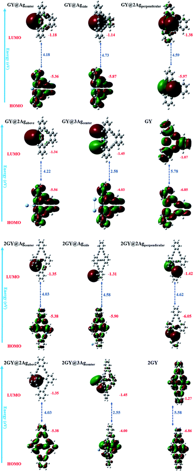
HOMO and LUMO energies together with their Eg are examined for both models 1 and 2 and their values are presented in Table 3. In pure GY and 2GY, HOMO lie at −6.85 and −6.86 eV respectively while their LUMOs lie at 1.07 and 1.27 eV with a Eg of 5.78 and 5.58 respectively. Practically charge mobility is governed by the Eg. Lower Eg allows the charge to be excited and transported more efficiently across the pi-conjugated system. Eg and electrical conductivity are intrinsically linked. Eg of all doped systems is narrow when compared to GY and lies at 4.18, 4.73, 4.59, 4.22, and 2.58 eV for GY@Agcenter, GY@Agside, GY@2Agperpendicular, GY@2Agabove, and GY@3Agcenter respectively. Narrow Eg in GY@3Agcenter validates enhanced conduction capacity. Due to low values Eg, all modeled doped systems (GY@Agcenter–GY@3Agcenter) are referred as polarizable, as well as efficient charge transfer complexes. Molecules of model 2 also indicated lower values of Eg as compared to their pure surface (2GY) and complexes of model 1 (GY–GY@3Agcenter). Lowest Eg is shown by 2GY@3Agcenter of 2.55 eV. Values of HOMOs and LUMOs are pictured in Fig. 7.
Table 3 HOMO and LUMO energies, Eg, vertical ionization energies (EVI), interaction energies (Eint) and binding energy (Eb) of all investigated molecular complexes
| Molecules |
HOMO (eV) |
LUMO (eV) |
Eg (eV) |
EVI (eV) |
Eint (kcal mol−1) |
Eb (eV) |
| GY |
−6.85 |
−1.07 |
5.78 |
6.85 |
— |
1.1 |
| GY@Agcenter |
−5.36 |
−1.18 |
4.18 |
5.36 |
−1.69 |
0.81 |
| GY@Agside |
−5.87 |
−1.14 |
4.73 |
5.87 |
−0.97 |
1.3 |
| GY@2Agperpendicular |
−5.97 |
−1.38 |
4.59 |
5.97 |
14.69 |
1.65 |
| GY@2Agabove |
−5.56 |
−1.34 |
4.22 |
5.56 |
−6.18 |
0.9 |
| GY@3Agcenter |
−4.03 |
−1.45 |
2.58 |
4.03 |
−9.44 |
0.27 |
| 2GY |
−6.86 |
−1.27 |
5.58 |
6.86 |
— |
1.07 |
| 2GY@Agcenter |
−5.38 |
−1.35 |
4.03 |
5.38 |
−1.57 |
0.74 |
| 2GY@Agside |
−5.90 |
−1.31 |
4.58 |
5.90 |
−0.93 |
1.28 |
| 2GY@2Agperpendicular |
−6.05 |
−1.42 |
4.62 |
6.05 |
14.41 |
1.87 |
| 2GY@2Agabove |
−5.38 |
−1.35 |
4.03 |
5.38 |
−5.95 |
0.94 |
| 2GY@3Agcenter |
−4.00 |
−1.45 |
2.55 |
4.00 |
−10.44 |
0.24 |
 |
| | Fig. 7 Graphical description of processed HOMO LUMO orbitals of (a) GY and (GY@Agcenter–GY@3Agcenter) and (b) 2GY and (2GY@Agcenter–2GY@3Agcenter). | |
Internal energy (Eint) refers to the stability of a molecule. Increase in Eint is associated with the increase in contact between dopant and surface, ultimately increasing the stability of the complex.39 To study the thermodynamic stability of our doped complexes (GY@Agcenter–GY@3Agcenter) vertical ionization energy EVI and Eint of complexes are determined computationally. From Table 3, it is inferred that values of Eint for GY@Agcenter, GY@Agside, GY@2Agperpendicular, GY@2Agabove, and GY@3Agcenter are −1.69, −0.97, 14.69, −6.18, and −9.44 kcal mol−1 respectively for model 1 complexes. Model 2 molecular systems, on the other hand, are more stable and possess strong interaction between 2Ag dopant in perpendicular direction with 2GY. Among all doped complexes, 2GY@2Agperpendicular is the most stable as it possesses the highest Eint. Likewise, the highest EVI is also revealed by 2GY@2Agperpendicular verifying it is a stable complex among doped systems.
To acquire a better understanding of structural stability of complexes binding energy (Eb) is computed theoretically. Eb of pure GY and 2GY surfaces as well doped systems (GY@Agcenter–2GY@3Agcenter) are calculated to explore the chemical stabilities using following eqn (6).40,41
Here
Eb is binding energy,
Eg is band gap and
Eopt is first excitation energy. Molecular systems possessing higher values of
Eb are chemically stable and retain strong interaction between pure
GY and dopants.
21 Among model 1 systems
GY@Agside and
GY@2Agperpendicular of newly doped systems explored higher values of
Eb when compared to pure
GY, confirming efficient doping strategy on
GY surface. Likewise, similar combinations of model 2
i.e.,
2GY@Agside and
2GY@2Agperpendicular showed higher
Eb. While comparing the
Eb of the two models, it was noticed that all of the molecules in model 2 showed a change in
Eb towards a higher value. Graphical representation of
Eb of all complexes is shown in
Fig. 8.
 |
| | Fig. 8 Graphical illustration of computed binding energy (Eb) of (a) GY and (GY@Agcenter–GY@3Agcenter) and (b) 2GY and (2GY@Agcenter–2GY@3Agcenter). | |
All analysed doped systems have their delocalization spread across the whole system.42 In all complexes distribution pattern of energy orbitals is similar in a manner that HOMOs are concentrated over surfaces (GY) and (2GY) whereas LUMOs are condensed majorly on dopant and negligibly on surfaces.42 FMO plots of pure GY and all studied molecules (GY@Agcenter–2GY@3Agcenter) along with their Eg are displayed in Fig. 9.
 |
| | Fig. 9 FMO plots and band gaps (Eg) of all studied complexes along with pure surfaces. | |
3.4 Density of states (DOS)
DOS is an analytical approach for analysing charge transport occupancy of states.43 Mulliken charge distribution has supported FMO results. DOS research reveals how the fragmentation of the molecules raises the HOMO and LUMO molecular orbitals.44 HOMO and LUMO energies can also be inferred via DOS approximations. DOS plots have been demonstrated to understand the role of the complexes and their fragments for the investigation of chemical bandgap. The DOS graphs of all researched molecules are evinced in Fig. 10. Table 4 summarizes the participation of various sections in formulating of molecular orbitals. In GY and 2GY, both HOMO and LUMO are formed completely by the contribution of the surfaces. The influence of several sections in making of molecular orbitals in (GY@Agcenter–GY@3Agcenter) and (2GY@Agcenter–2GY@3Agcenter) is same. In these doped complexes, HOMO is acquired principally by the dopant and insignificantly by surfaces (GY and 2GY) while in the formation of LUMO GY and 2GY plays a substantial role.
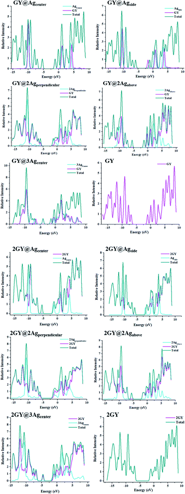 |
| | Fig. 10 DOS charts for molecules od model 1 and model 2. | |
Table 4 Surface and dopant role in developing the HOMO and LUMO of surface and all doped complexes
| Molecules |
HOMO = H |
GY |
Dopant |
| LUMO = L |
| GY |
H |
100 |
— |
| L |
100 |
— |
| GY@Agcenter |
H |
3.3 |
96.7 |
| L |
100 |
0 |
| GY@Agside |
H |
0.6 |
99.4 |
| L |
99.7 |
0.3 |
| GY@2Agperpendicular |
H |
47.2 |
52.8 |
| L |
9.5 |
90.5 |
| GY@2Agabove |
H |
2.4 |
97.6 |
| L |
99.7 |
0.3 |
| GY@3Agcenter |
H |
0.6 |
99.4 |
| L |
100 |
0 |
| 2GY |
H |
100 |
— |
| L |
100 |
— |
| 2GY@Agcenter |
H |
1.8 |
98.2 |
| L |
97.0 |
3.0 |
| 2GY@Agside |
H |
0.1 |
99.9 |
| L |
99.3 |
0.7 |
| 2GY@2Agperpendicular |
H |
1.0 |
99.0 |
| L |
98.3 |
1.7 |
| 2GY@2Agabove |
H |
10.5 |
89.5 |
| L |
47.6 |
52.4 |
| 2GY@3Agcenter |
H |
18.8 |
81.2 |
| L |
82.7 |
17.3 |
3.5 Dipole moment (μ)
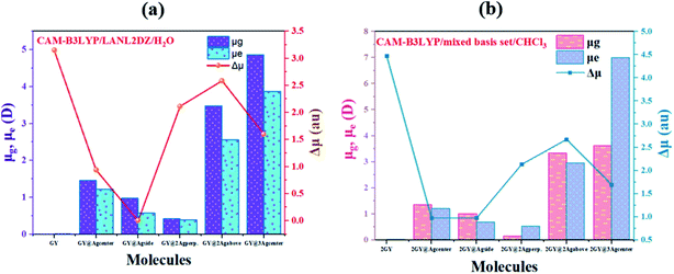
The dipole moment (μ) plays a key role in molecular packing and crystallinity.45 The more the crystalline material is, the less likely it is for charge transfer states to behave abnormally.46 Dipole moment in gaseous (μg), excited phase (μe) and transition electric dipole moment (Δμ) is estimated using CAM-B3LYP/LANL2DZ functional for model 1 molecules while model 2 molecular systems are discussed using CAM-B3LYP functional with mixed basis set. Computed values of dipole moments are reviewed in Table 5. Findings showed that all our doped molecules (GY@Agcenter–GY@3Agcenter) and (2GY@Agcenter–2GY@3Agcenter) acquired more μg and μe than their respective surfaces (GY and 2GY).
Table 5 Computed dipole moment of all doped complexes of model 1 and model 2 in gaseous phase (μg), excited phase (μe) and transition electric dipole moment (Δμ)
| Molecules |
μg (D) |
μe (D) |
Δμ (au) |
| GY |
0.001 |
0.001 |
3.157 |
| GY@Agcenter |
1.455 |
1.218 |
0.940 |
| GY@Agside |
0.975 |
0.570 |
0.004 |
| GY@2Agperpendicular |
0.418 |
0.385 |
2.115 |
| GY@2Agabove |
3.479 |
2.556 |
2.588 |
| GY@3Agcenter |
4.871 |
3.873 |
1.601 |
| 2GY |
0.001 |
0.001 |
4.48 |
| 2GY@Agcenter |
1.349 |
1.191 |
0.97 |
| 2GY@Agside |
0.999 |
0.671 |
0.97 |
| 2GY@2Agperpendicular |
0.136 |
0.509 |
2.13 |
| 2GY@2Agabove |
3.341 |
2.939 |
2.67 |
| 2GY@3Agcenter |
3.628 |
6.998 |
1.69 |
Pure GY and 2GY reveal lower μg and μe of 0.001 and 0.001 D respectively due to symmetry in its structure. Among all molecules of model 1, GY@3Agcenter revealed maximum value of μg (4.871 D) and μe (3.873 D) possessing three Ag atom clusters which facilitate self-assembly and aid in multilayer fabrication. Increasing order of μe is GY< GY@2Agperpendicular< GY@Agside< GY@Agcenter< GY@2Agabove< GY@3Agcenter. Same trend of increasing dipole moment is followed in the gaseous state. Hence, significant NLO properties can be achieved. Likewise, model 2 molecules also illustrated a significant shift towards high value in comparison with 2GY and model 1 system. The impressive change in μ infers that complexes have arrayed themselves so as to limit recombination of charges. Dipole moments are graphically illustrated in Fig. 11.
 |
| | Fig. 11 Graphical representation of dipole moments at ground (μg), excited (μe) and transition electric dipole moment (Δμ) of (a) GY and complexes GY@Agcenter–GY@3Agcenter and (b) 2GY and complexes 2GY@Agcenter–2GY@3Agcenter. | |
3.6 Transition density matrix (TDM)
TDM refers to the matrix that dispenses information about charge transition locations and quantum geometry of doped molecules in excited state.47,48 In TDM plots, the number of atoms is given on the x-axis and y-axis (left side) while on the right side of the y-axis coefficient of transition or electron density is displayed. Using the specified hybrid DFT functional, TDM analysis of pure GY and 2GY and currently doped molecules (GY@Agcenter–GY@3Agcenter) and (2GY@Agcenter–2GY@3Agcenter) has been accomplished. Because of insignificant contributions in transitions, hydrogens atoms have been overlooked. Fig. 12 shows a visual representation of all molecules. GY and 2GY are divided into one component while all other systems are sequestered into two fractions: surface and dopant.
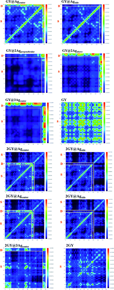 |
| | Fig. 12 TDM plots of pure surfaces and all molecular systems of model 1 and model 2. (a) GY and (GY@Agcenter–GY@3Agcenter) and (b) 2GY and (2GY@Agcenter–2GY@3Agcenter). | |
In pure GY and 2GY, charge distribution and coherency can be accomplished by valuable diagonal as well as off-diagonal charge transfer. In all designed doped materials, electronic distribution is concentrated on dopant portions. The bright spots on TDM are pointing to the atom number where the transition population was detected. The doped materials had exhibited enhanced charge transfer from surface to dopant. So, (GY@Agcenter–GY@3Agcenter) and (2GY@Agcenter–2GY@3Agcenter) exhibit marvellous charge separation capability when studied in contrast to pure GY and 2GY, as a result, they can be used as unintentional aspirants for future NLO materials with improved characteristics.
3.7 NLO properties
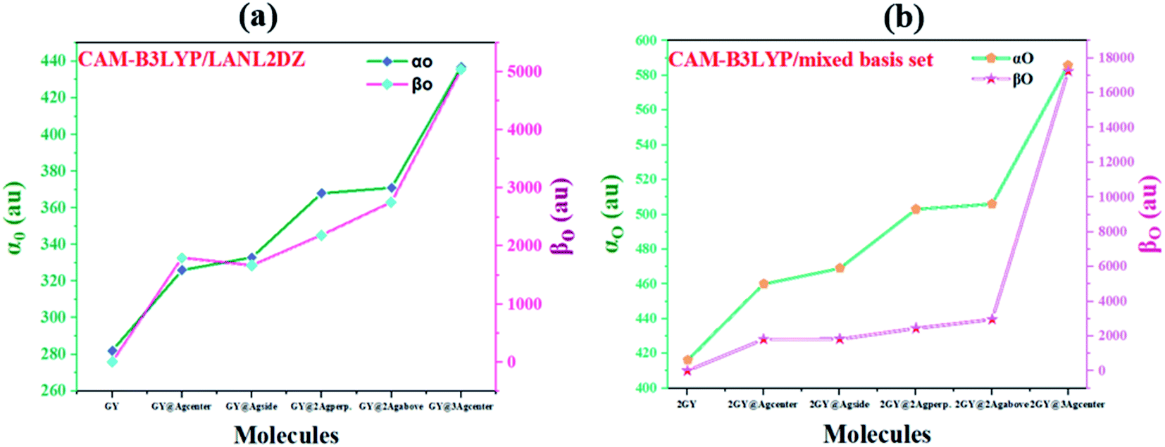
The most persuasive parameter to quantify the NLO properties of pure GY and doped materials is linear polarizability (αO) first hyperpolarizability (βO).49 Both αO and βO of all molecules of model 1 and 2 are evaluated computationally at their respective functionals and basis set, and outcomes are disclosed in Table 6. Values of αO and βO of all complexes (GY@Agcenter–GY@3Agcenter) are contrasted with pure GY. αO of pure GY surface lies at 282 au while doping of Ag clusters had prominently increased αO in all doped complexes. αO of GY@Agcenter, GY@Agside, GY@2Agperpendicular, GY@2Agabove, and GY@3Agcenter are 326, 333, 368, 371, and 437 au respectively. 55% increase in linear polarizability αO of GY@3Agcenter (437 au) is observed considering GY surface as a reference.
Table 6 Computed linear (αO) and first hyperpolarizability (βO) of surface as well as doped complexes
| Molecules |
αO (au) |
βO (au) |
| GY |
282 |
0.21 |
| GY@Agcenter |
326 |
1797 |
| GY@Agside |
333 |
1667 |
| GY@2Agperpendicular |
368 |
2188 |
| GY@2Agabove |
371 |
2757 |
| GY@3Agcenter |
437 |
5049 |
| 2GY |
416 |
0.06 |
| 2GY@Agcenter |
460 |
1816 |
| 2GY@Agside |
469 |
1828 |
| 2GY@2Agperpendicular |
503 |
2449 |
| 2GY@2Agabove |
506 |
2964 |
| 2GY@3Agcenter |
586 |
17270 |
According to the literature, the NLO performance of a doped complex can be substantially intensified by the incorporation of surplus electrons. High energy HOMO levels are occupied by surplus electrons, leading to a decrease in Eg and elevation in βO.10 βO of pure GY calculated computationally is 0.21 au. Pronounced shift in βO of all doped complexes (GY@Agcenter–GY@3Agcenter) is observed. The βO of all investigated complexes is decreasing as GY@3Agcenter (5049 au) > GY@2Agabove (2757 au) > GY@2Agperpendicular (2188 au) > GY@Agcenter (1797 au) > GY@Agside (1667 au) > GY (0.21 au). Molecular systems of model 2 (2GY@Agcenter–2GY@3Agcenter) indicated sharp increase in αO and βO of complexes. 2GY@3Agcenter acquired βO of 17270 au. The graphical representation of αO and βO is pictured in Fig. 13, representing βO has increased several folds when studied in comparison with GY. Keeping in view the analysis of NLO properties, it is inferred that all our designed doped complexes specially complexes having two-unit cells of GY i.e., (2GY@Agcenter–2GY@3Agcenter), will exhibit magnificent NLO responses.
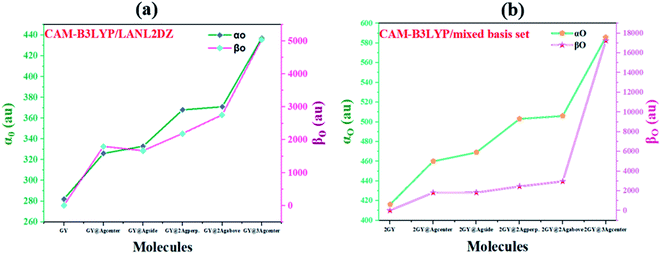 |
| | Fig. 13 Graphical representation of computed polarizabilities (a) GY and complexes GY@Agcenter–GY@3Agcenter and (b) 2GY and complexes 2GY@Agcenter–2GY@3Agcenter. | |
3.8 Electron density and electrostatic potential (ESP) analysis
Electron density (ED) analysis grasps information regarding the reactivity of atoms and the presence of reactive sites for nucleophilic and electrophilic attack based on the distribution of the Milliken charge on the whole molecule.50 ESP is also crucial in predicting the correlation among molecular structure, molecular interaction, as well as photophysical properties of molecules.51 The electrophilic and nucleophilic regions of researched molecules are determined using ESP simulations conducted at optimal DFT functional. In ESP diagrams, red hue reflects the electrophilic, electron rich and negative ESP zone whereas the green hue signifies neutral zone, and the blue hue is concentrated on the nucleophilic, electrons deficient and positive ESP zone.36
ESP analysis of all doped complexes along with GY and 2GY is done theoretically. Fig. 14 shows ESP diagrams of the pure surfaces along with freshly doped complexes. ESP diagrams of complexes of model 1 and model 2 demonstrate that the red color (negative potential) is concentrated on the acetylene region of the graphyne surface making it more electrophilic. The region where Ag dopant exists and backbone chain of surface in each molecular framework (GY@Agcenter–GY@3Agcenter) and (2GY@Agcenter–2GY@3Agcenter), possess blue color (positive potential) and behave as a nucleophile.
 |
| | Fig. 14 ESP images of pure GY as well as GY@Agcenter–GY@3Agcenter and 2GY as well as 2GY@Agcenter–2GY@3Agcenter. | |
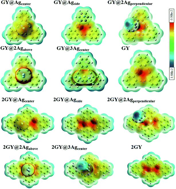
3.9 Electron density distribution matrix (EDDM)
To comprehend the charge transfer capacity, EDDM evaluations were also executed in which molecular orbitals of excited state are subtracted from ground state.52 EDDM of all doped complexes (GY@Agcenter–GY@3Agcenter) along with GY is evaluated computationally at CAM-B3LYP/LANL2DZ functional while analysis of (2GY@Agcenter–2GY@3Agcenter) is done at CAMB3LYP/mixed basis set. EDDM graphs show the reorganization of electrons in pure surfaces and doped complexes. Fig. 15 shows the net charge density of subtracted complexes. Sea-green color in EDDM diagrams reveals a positive value of charge density while purple color illustrates the negative value and reduced electron density upon excitation. Charge distribution pattern in GY, 2GY, GY@Agcenter, 2GY@Agcenter, GY@Agside, 2GY@Agside, 2GY@2Agabove, and GY@3Agcenter, 2GY@3Agcenter, is analogous, in such a way that charge density is distributed evenly over the entire system. But in GY@2Agperpendicular, 2GY@2Agperpendicular, and GY@2Agabove charge distribution is mainly concentrated on dopant units.
 |
| | Fig. 15 EDDM images of pure GY as well as GY@Agcenter–GY@3Agcenter and 2GY as well as 2GY@Agcenter–2GY@3Agcenter. | |
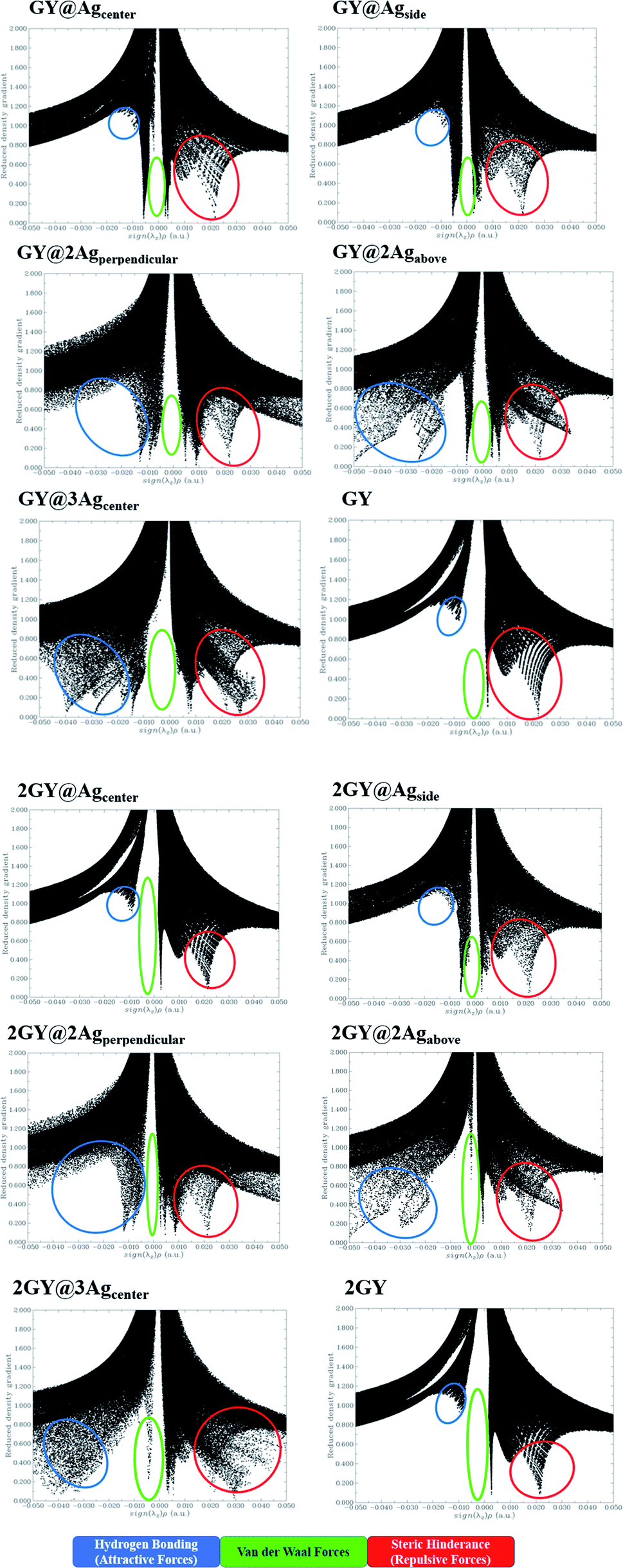
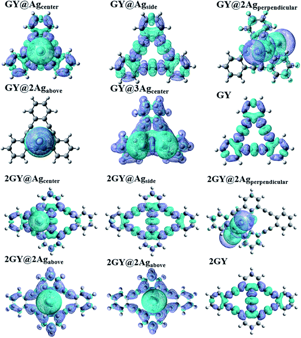
3.10 Non-covalent interaction (NCI) analysis
The NCI assessment gives valuable information regarding a molecule's non-covalent interactions.53 NCI plot can distinguish between the molecular areas with weak interactions and those with strong directional attractions associated with localised atom–atom linkages.54 Fig. 16 depicts the scatter graphs drawn between the reduced density gradient and the electron density (r), oriented by the sign of λ2.55 NCI analysis appears to be a superior alternative for using data about hydrogen bonding, van der Waals forces, and steric hindrance inside a system to improve information on the molecular stability in small or large molecules.55 The scatter graphs are created with Multiwfn software. The (λ2) ρ values can be used to predict the nature of interaction: if (λ2) ρ > 0 then the interaction is repulsive, and if (λ2) ρ < 0 then the interaction is attractive that is also highlighted by color-filled 3D isosurface of complexes and graphyne, shown in Fig. 16. The NCI graphs of all doped systems along with surfaces (GY and 2GY) show that strong attractive forces exist between the complex molecules that is advantageous for propitious NLO materials. The H-bond (attractive) is shown by the blue tone, the van der Waals interactions are indicated by the green hue, and the steric effect is indicated by the red region (repulsive) (Fig. 17).
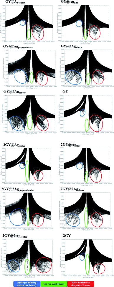 |
| | Fig. 16 NCI images for molecular complexes of model 1 as well as model 2. | |
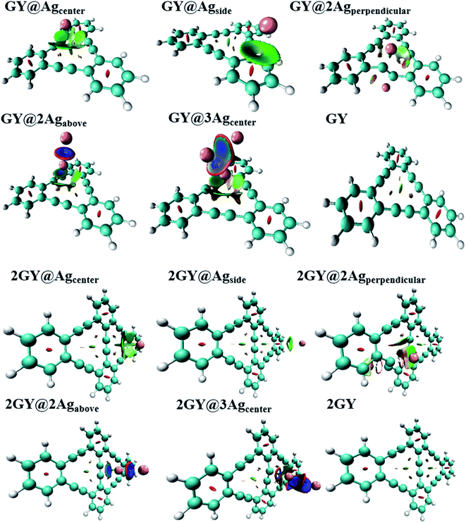 |
| | Fig. 17 Pictorial representation of 3D isosurface of all molecular complexes of model 1 as well as model 2. | |
3.11 Infrared (IR) analysis
Infrared (IR) spectrum characteristics of pure graphyne and doped complexes are researched to analyze how they change with doping. Fig. 18 depicts the IR spectrum. In all IR spectra, frequencies around 64 to 77 cm−1 are due to wagging vibrations except for GY@3Agcenter and 2GY@3Agcenter where 80 cm−1 frequency is for scissoring vibrations. Vibrational frequencies at around 800 cm−1, 1550 cm−1, and 3200 cm−1 in all systems are related to twisting, scissoring, and symmetrical stretching vibrations. Detailed study of vibrational frequencies of all studied molecules is illustrated in Table 7.
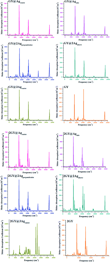 |
| | Fig. 18 IR plots of pure surfaces and all molecular systems of model 1 and model 2. | |
Table 7 Computed IR frequencies of pure surface as well as all doped complexes
| Molecules |
Frequency (cm−1) |
Vibrations |
Molecules |
Frequency (cm−1) |
Vibrations |
| GY |
64 |
Wagging |
2GY |
75 |
Wagging |
| 824 |
Twisting |
822 |
Twisting |
| 1561 |
Scissoring |
1557 |
Scissoring |
| 3266 |
Symmetrical stretching |
3267 |
Symmetrical stretching |
| GY@Agcenter |
66 |
Wagging |
2GY@Agcenter |
64 |
Wagging |
| 824 |
Twisting |
825 |
Twisting |
| 1560 |
Scissoring |
1557 |
Scissoring |
| 3266 |
Symmetrical stretching |
3267 |
Symmetrical stretching |
| GY@Agside |
64 |
Wagging |
2GY@Agside |
76 |
Wagging |
| 823 |
Twisting |
828 |
Twisting |
| 1561 |
Scissoring |
1557 |
Scissoring |
| 3267 |
Symmetrical stretching |
3255 |
Symmetrical stretching |
| GY@2Agperpendicular |
74 |
Wagging |
2GY@2Agperpendicular |
74 |
Wagging |
| 822 |
Twisting |
822 |
Twisting |
| 1535 |
Scissoring |
1535 |
Scissoring |
| 2348 |
Asymmetrical stretching |
2348 |
Asymmetrical stretching |
| 3264 |
Symmetrical stretching |
3264 |
Symmetrical stretching |
| GY@2Agabove |
77 |
Wagging |
2GY@2Agabove |
96 |
Wagging |
| 823 |
Twisting |
825 |
Twisting |
| 1561 |
Scissoring |
1553 |
Scissoring |
| 3268 |
Symmetrical stretching |
3266 |
Symmetrical stretching |
| GY@3Agcenter |
80 |
Scissoring |
2GY@3Agcenter |
84 |
Scissoring |
| 823 |
Twisting |
823 |
Twisting |
| 1558 |
Scissoring |
2204 |
Scissoring |
| 3268 |
Symmetrical stretching |
3264 |
Symmetrical stretching |
3.12 Electrical conductivity (σ)
Most crucial aspect in determining the electrical conductivity (σ) of doped complexes for NLO properties is Eg. After adsorbing the silver (Ag) clusters on the surface (GY and 2GY), these unique complexes (GY@Agcenter–GY@3Agcenter) and (2GY@Agcenter–2GY@3Agcenter) become more semiconductor-like owing to their narrow Eg. Therefore, it is envisaged that the σ is increased as compared to pure surface and can be determined using eqn (6).56| |
 | (7) |
Here, σ is electrical conductivity, Eg is the band gap, k is Boltzmann constant and T is the temperature in kelvin. From the equation, it is inferred that the doped complexes possessing lower Eg will have higher σ because it is exponentially correlated to Eg.57 In our investigation of model 1 systems, Eg of all newly designed doped complexes has smaller values (in the range of 2.58 to 4.73 eV) in comparison with pure GY (5.78 eV) as indicated in Table 3 leading to the significant increase in electrical conductivities of doped complexes (GY@Agcenter–GY@3Agcenter). Likewise, all molecular systems (2GY@Agcenter–2GY@3Agcenter) are accompanied by relatively lower Eg and higher electrical conductivity (σ). Electrical conductivity of complexes lies in the order of 2GY@3Agcenter > 2GY@Agcenter = 2GY@2Agabove >2GY@Agside >2GY@2Agperpendicular > 2GY. An increase in σ has resulted from strong dopant–surface interaction and efficient n → σ* charge transfer. Thus, our designed Ag cluster doped complexes on the 2GY surface may behave as unique sensing materials.
4. Conclusion
The current study relies on the comprehensive analysis of Ag cluster doped with graphyne surface in two distinct ways. In model 1, one-unit cell graphyne (GY) doped with variable Ag clusters produced complexes namely GY@Agcenter, GY@Agside, GY@2Agperpendicular, GY@2Agabove, GY@3Agcenter, and employ CAM-B3LYP/LANL2DZ functional to explore the NLO properties. While in model 2, two-unit cell graphyne (2GY) doped with Ag are designed namely 2GY@Agcenter, 2GY@Agside, 2GY@2Agperpendicular, 2GY@2Agabove, 2GY@3Agcenter and their NLO properties are studied at CAM-B3LYP/mixed basis set. To study charge distribution FMOs, DOS, EDDM, TDM, and ESP analysis were directed. Using EVI and Eint, the thermodynamic stability of complexes has been explored. The simulated outcomes of all complexes lie in the range of efficient NLO material such as red-shifted λmax, ameliorated αO and βO, narrowed Eg and lowered Eopt of all doped complexes in comparison with pure GY and 2GY. Among molecular complexes of model 1; highest λmax is exhibited by GY@3Agcenter (536 nm) with the lowest Eopt of 2.31 eV among all molecular systems. The newly doped systems (GY@Agcenter–GY@3Agcenter) are enriched with a higher dipole moment μe (0.385–3.873 D) in H2O than GY (0.001 D). Likewise, 2GY@3Agcenter has highest λmax of 548 nm, lowest Eopt of 2.31 eV and much narrower Eg of 2.55 eV in model 2 complexes (2GY@Agcenter–2GY@3Agcenter). Infrared (IR) and NCI analysis are performed to study the types of vibrations associated and nature of interaction. Higher values of electrical conductivities of all complexes resulted from strong dopant–surface interaction and efficient n → σ* charge transfer. All computationally computed parameters advocate the potential of using all doped complexes of model 1 as well as model 2 in integrated NLO devices and open new routes for designing highly efficient NLO materials. Moreover, more virtuous and upstanding outcomes have been revealed by complexes in which graphyne surface was comprised of two-unit cell. To sum up, the current research yields deep insight into tuneable NLO characteristics of Ag doped on graphyne surface.
Author contributions
Saba Zahid: major contribution, the acquisition, drafting, analysis, writing original paper, working and interpretation of data.
Alvina Rasool: the acquisition, drafting, analysis, working, and interpretation of data.
Ali Raza Ayub: the acquisition, drafting, analysis, working, and interpretation of data.
Khurshid Ayub: the acquisition, drafting, analysis, working, and interpretation of data.
Javed Iqbal*: substantial contribution to research design, the acquisition, analysis, and interpretation of data, and approval of the submitted and final version. M. S. Al-Buriahi: the acquisition, drafting, analysis, working, and interpretation of data. Norah Alwadai: the acquisition, drafting, analysis, working, and interpretation of data. H. H. Somaily: the acquisition, drafting, analysis, working, and interpretation of data.
Conflicts of interest
There are no declared conflicts.
Acknowledgements
The authors thank the Punjab Bio-energy Institute (PBI), University of Agriculture (UAF), Faisalabad 38000, Pakistan, for financial and technical support. The authors express their gratitude to Princess Nourah bint Abdulrahman University Researchers Supporting Project (Grant No. PNURSP2022R11), Princess Nourah bint Abdulrahman University, Riyadh, Saudi Arabia. This work was supported by King Khalid University through a grant (RCAMS/KKU/G001/21) under the Research Center for Advanced Materials Science (RCAMS) at King Khalid University, Saudi Arabia.
References
- A. Ahsin and K. Ayub, Optik, 2021, 227, 166037 CrossRef CAS.
- O. Mhibik, S. Forget, D. Ott, G. Venus, I. Divliansky, L. Glebov and S. Chénais, Light: Sci. Appl., 2016, 5, e16026 CrossRef CAS PubMed.
- C. J. Brabec, Sol. Energy Mater. Sol. Cells, 2004, 83, 273–292 CrossRef CAS.
- H. Hasegawa and T. Sato, Electrochim. Acta, 2005, 50, 3015–3027 CrossRef CAS.
- C. Cheng, C. Zhu, B. Huang, H. Zhang, H. Zhang, R. Chen, W. Pei, Q. Chen and H. Chen, Adv. Mater. Technol., 2019, 4, 1800729 CrossRef CAS.
- J. M. Hales, M. Cozzuol, T. E. Screen, H. L. Anderson and J. W. Perry, Opt Express, 2009, 17, 18478–18488 CrossRef CAS PubMed.
- S. Achelle, C. Baudequin and N. Plé, Dyes Pigm., 2013, 98, 575–600 CrossRef CAS.
- S. S. Varghese, S. Lonkar, K. Singh, S. Swaminathan and A. Abdala, Sens. Actuators, B, 2015, 218, 160–183 CrossRef CAS.
- A. Karakas, A. Elmali and H. Unver, Spectrochim. Acta, Part A, 2007, 68, 567–572 CrossRef PubMed.
- R. Baloach, K. Ayub, T. Mahmood, A. Asif, S. Tabassum and M. A. Gilani, J. Inorg. Organomet. Polym. Mater., 2021, 31, 3062–3076 CrossRef CAS.
- M. Ishaq, R. A. Shehzad, M. Yaseen, S. Iqbal, K. Ayub and J. Iqbal, J. Mol. Model., 2021, 27, 1–11 CrossRef PubMed.
- S. Muhammad, M. R. S. A. Janjua and Z. Su, J. Phys. Chem. C, 2009, 113, 12551–12557 CrossRef CAS.
- R. A. Shehzad, S. Muhammad, J. Iqbal, A. G. Al-Sehemi, M. Yaseen, Z. Aloui and M. Khalid, J. Mol. Model., 2021, 27, 1–10 CrossRef PubMed.
- A. U. Khan, S. Muhammad, R. A. Khera, R. A. Shehzad, K. Ayub and J. Iqbal, Optik, 2021, 231, 166464 CrossRef CAS.
- A. Irfan, M. Pannipara, A. G. Al-Sehemi, M. W. Mumtaz, M. A. Assiri, A. R. Chaudhry and S. Muhammad, Z. Phys. Chem. (Muenchen, Ger.), 2019, 233, 1625–1644 CrossRef CAS.
- D. Xiao, F. A. Bulat, W. Yang and D. N. Beratan, Nano Lett., 2008, 8, 2814–2818 CrossRef CAS PubMed.
- L. Zhu, K. Xue and J. Hou, J. Mol. Model., 2019, 25, 1–10 CrossRef CAS PubMed.
- M. J. Lee, M. Piao, M.-Y. Jeong, S. H. Lee, K. M. Kang, S.-J. Jeon, T. G. Lim and B. R. Cho, J. Mater. Chem., 2003, 13, 1030–1037 RSC.
- Y.-D. Song and Q.-T. Wang, Optik, 2020, 220, 164947 CrossRef CAS.
- R. Baughman, H. Eckhardt and M. Kertesz, J. Chem. Phys., 1987, 87, 6687–6699 CrossRef CAS.
- X. Li and S. Li, J. Mater. Chem. C, 2019, 7, 1630–1640 RSC.
- M. Zhang, X. Wang, H. Sun, J. Yu, N. Wang, Y. Long and C. Huang, 2D Materials, 2018, 5, 035039 CrossRef.
- A. Bhaskar, R. Guda, M. M. Haley and T. Goodson III, J. Am. Chem. Soc., 2006, 128, 13972–13973 CrossRef CAS PubMed.
- K. Srinivasu and S. K. Ghosh, J. Phys. Chem. C, 2012, 116, 5951–5956 CrossRef CAS.
- H. Zhang, X. Zhao, M. Zhang, Y. Luo, G. Li and M. Zhao, J. Phys. D: Appl. Phys., 2013, 46, 495307 CrossRef.
- M. Frisch, G. Trucks, H. Schlegel, G. Scuseria, M. Robb, J. Cheeseman, G. Scalmani, V. Barone, B. Mennucci and G. Petersson, Google Scholar There is no corresponding record for this reference, 2015 Search PubMed.
- T. Yanai, D. P. Tew and N. C. Handy, Chem. Phys. Lett., 2004, 393, 51–57 CrossRef CAS.
- A. Klamt, C. Moya and J. Palomar, J. Chem. Theory Comput., 2015, 11, 4220–4225 CrossRef CAS PubMed.
- S. Gorelsky, A Library for Package-Independent Computational Chemistry Algorithms, University of Ottawa, Ottawa, Canada, 2010 Search PubMed.
- A. S. Rad and K. Ayub, J. Alloys Compd., 2016, 672, 161–169 CrossRef.
- R. A. Shehzad, J. Iqbal, K. Ayub, F. Nawaz, S. Muhammad, A. R. Ayub and S. Iqbal, Optik, 2021, 226, 165923 CrossRef CAS.
- N. M. O’boyle, A. L. Tenderholt and K. M. Langner, J. Comput. Chem., 2008, 29, 839–845 CrossRef PubMed.
- T. Lu and F. Chen, J. Comput. Chem., 2012, 33, 580–592 CrossRef CAS PubMed.
- M. R. S. A. Janjua, C.-G. Liu, W. Guan, J. Zhuang, S. Muhammad, L.-K. Yan and Z.-M. Su, J. Phys. Chem. A, 2009, 113, 3576–3587 CrossRef CAS PubMed.
- M. R. S. A. Janjua, Z. H. Yamani, S. Jamil, A. Mahmood, I. Ahmad, M. Haroon, M. H. Tahir, Z. Yang and S. Pan, Aust. J. Chem., 2015, 69, 467–472 CrossRef.
- S. Zahid, A. Rasool, M. Ans, M. Yaseen and J. Iqbal, Energy Fuels, 2021, 35, 15018–15032 CrossRef CAS.
- A. Rasool, S. Zahid, R. A. Shehzad, M. S. Akhter and J. Iqbal, Comput. Theor. Chem., 2021, 1203, 113359 CrossRef CAS.
- A. U. Khan, R. A. Khera, N. Anjum, R. A. Shehzad, S. Iqbal, K. Ayub and J. Iqbal, RSC Adv., 2021, 11, 7779–7789 RSC.
- F. Ullah, N. Kosar, K. Ayub, M. A. Gilani and T. Mahmood, New J. Chem., 2019, 43, 5727–5736 RSC.
- S. Zahid, A. Rasool, M. Ans, M. Salim Akhter, J. Iqbal, M. S. Al-Buriahi, S. Alomairy and Z. A. Alrowaili, Sol. Energy, 2022, 231, 793–808 CrossRef CAS.
- A. Rasool, S. Zahid, M. Ans, J. Iqbal, M. Adnan, E.-S. M. Sherif and M. S. Al-Buriahi, Opt. Mater., 2022, 123, 111907 CrossRef.
- R. Habibpour and R. Vaziri, Int. J. Nano Dimens., 2016, 7, 208–224 CAS.
- G. Landi, H. C. Neitzert, C. Barone, C. Mauro, F. Lang, S. Albrecht, B. Rech and S. Pagano, Adv. Sci., 2017, 4, 1700183 CrossRef PubMed.
- F. Ullah, N. Kosar, M. N. Arshad, M. A. Gilani, K. Ayub and T. Mahmood, Opt Laser. Technol., 2020, 122, 105855 CrossRef CAS.
- H. H. Cho, S. Kim, T. Kim, V. G. Sree, S. H. Jin, F. S. Kim and B. J. Kim, Adv. Energy Mater., 2018, 8, 1701436 CrossRef.
- F. Manzoor, J. Iqbal, Z. Zara, B. Eliasson, M. S. Mahr and K. Ayub, ChemistrySelect, 2018, 3, 1593–1601 CrossRef CAS.
- S. Zahid, A. Rasool, R. A. Shehzad, I. A. Bhatti and J. Iqbal, J. Mol. Model., 2021, 27, 1–14 CrossRef PubMed.
- A. Rasool, S. Zahid, M. Ans, S. Muhammad, K. Ayub and J. Iqbal, ACS Omega, 2021, 7, 844–862 CrossRef PubMed.
- M. U. Khan, M. Ibrahim, M. Khalid, S. Jamil, A. A. Al-Saadi and M. R. S. A. Janjua, Chem. Phys. Lett., 2019, 719, 59–66 CrossRef CAS.
- S. Iyasamy, K. Varadharajan and S. Sivagnanam, Z. Phys. Chem. (Muenchen, Ger.), 2016, 230, 1681–1710 CrossRef CAS.
- M. Drissi, N. Benhalima, Y. Megrouss, R. Rachida, A. Chouaih and F. Hamzaoui, Molecules, 2015, 20, 4042–4054 CrossRef CAS PubMed.
- R. Kiran, R. A. Khera, A. U. Khan, A. Ayoub, N. Iqbal, K. Ayub and J. Iqbal, J. Mol. Struct., 2021, 1236, 130348 CrossRef CAS.
- I. Munir, M. Perveen, S. Nazir, R. A. Khera, A. R. Ayub, K. Ayub and J. Iqbal, J. Mol. Liq., 2021, 336, 116327 CrossRef CAS.
- M. D. Mohammadi, 2021.
- M. D. Mohammadi and H. Y. Abdullah, J. Mol. Model., 2020, 26, 1–15 CrossRef PubMed.
- X. Li and J. Lu, Phys. Chem. Chem. Phys., 2019, 21, 13165–13175 RSC.
- L. Ma, J.-M. Zhang, K.-W. Xu and V. Ji, Appl. Surf. Sci., 2015, 343, 121–127 CrossRef CAS.
Footnote |
| † Electronic supplementary information (ESI) available: Optimized cartesian coordinates of our studied compounds are also available. See DOI: 10.1039/d1ra08117a |
|
| This journal is © The Royal Society of Chemistry 2022 |
Click here to see how this site uses Cookies. View our privacy policy here. 
 Open Access Article
 This Open Access Article is licensed under a Creative Commons Attribution-Non Commercial 3.0 Unported Licence
 a,
Alvina Rasoola,
Ali Raza Ayuba,
Khurshid Ayub
a,
Alvina Rasoola,
Ali Raza Ayuba,
Khurshid Ayub