 Open Access Article
Removal of U(VI) from aqueous solutions by an effective bio-adsorbent from walnut shell and cellulose composite-stabilized iron sulfide nanoparticles†
Zhengfeng Huab,
Huifang Wanga,
Renrong Liua,
Baowei Hu a and
Muqing Qiu
 *a
*a
aSchool of Life Science, Shaoxing University, Huancheng West Road 508, Shaoxing, 312000, P. R. China. E-mail: qiumuqing@usx.edu.cn
bEco-Envrionmental Science & Research Institute of Zhejiang Province, Hangzhou 310007, China
First published on 20th January 2022
Abstract
FeS nanoparticles were easily aggregated and oxidized in the natural environment. It was important to stabilize the iron sulfide nanoparticle composite with a stabilizer. Biochar could be used as an effective carrier to inhibit the agglomeration and oxidization of FeS nanoparticles. An efficient and novel bio-adsorbent (CFeS-WS) from walnut shell (WS) and cellulose composites-stabilized iron sulfide nanoparticle was synthesized by the modified method. The removal of U(VI) ions from an aqueous solution by CFeS-WS was carried out. The experimental results indicated that numerous functional groups were observed on the surface of CFeS-WS. In addition, the biochar was loaded successfully with cellulose and FeS nanoparticle composites. The cellulose and biochar effectively prevented the agglomeration of FeS nanoparticles. The adsorption process of U(VI) ions by CFeS-WS was more consistent with the pseudo second-order kinetic model and Langmuir isotherm model. The adsorption process of U(VI) ions was an endothermic and chemical reaction process. The proposed reaction mechanism of the U(VI) ion removal by CFeS-WS mainly consisted of the ion exchange reaction, reduction reaction, hydrogen bonding and functional group, and pore of the adsorbent filling. According to the results of the recycle experiment, it indicated that the chemical stability of CFeS-WS was good.
Introduction
For nuclear energy, uranium is the main fuel in the nuclear industry and the main component of nuclear waste.1–3 Because of its low price and non-polluting advantages, it is considered to be one of the potential substitutes for fossil fuels in the future.4,5 However, uranium also is radioactive and carcinogenic for a long time. Even a small amount of uranium may cause serious harm to human health and the environment.6–8 Therefore, the disposal of nuclear waste is a very challenging and urgent problem that needs to be solved.9,10 Recently, chemical, electrolytic, ion exchange, membrane separation and adsorption methods have been used to remove U(VI) ions in solutions.11,12 However, some treatment methods (except for the adsorption method) could not be applied to the engineering because of their high cost, low adsorption capacity, secondary pollution and complex operation processes. From the perspective of economic and practical efficiency advantages, adsorption technology has gradually attracted the attention of researchers.13–16 This method is thought to be an effective technology to eliminate U(VI) due to its low cost, easy large-scale production and environmental friendliness. Therefore, how to choose the adsorbent materials is very important. Various adsorbents are applied into the treatment of radioactive wastewater.17–22 Numerous adsorbents (such as carbon fibers, carbon nanotubes and graphene oxide) have been applied to the removal of U(VI) from the environment.23–26In recent years, the application of iron-based materials was studied because of their environmental friendliness and high treatment processing efficiency. Therefore, this has attracted the attention of many scholars.27 Increasing number of researchers have begun to develop different iron-based materials to remove the radioactive uranium from wastewater.28–31 Ferrous sulfide (FeS) is one of the iron-based materials.32 Compared with other iron-based materials, it is more effective in treating U(VI) wastewater due to the presence of Fe2+ ions and S2− ions.33–37 Because of their large volume ratio and high reactivity, nanoparticles are widely used to treat pollutants in sewage and soil.38,39 However, FeS nanoparticles are easily aggregated and oxidized in the natural environment due to van der Waals forces between the nanoparticles. This reduces the reactivity between the nanoparticles and pollutants. This reduces the contact area between the nanoparticles and pollutants, and thus affects the reactivity between them. This problem has become an important factor limiting the application of FeS nanoparticles in pollution treatment. It was very important to look for a suitable stabilizer to modify FeS nanoparticles.
Various techniques have been tested to overcome the shortcoming of FeS nanoparticles, such as silica, sepiolite, activated carbon and biochar.40–46 Compared with other materials, biochar presented some advantages.47,48 These included their large specific surface area, high stability, low bulk density, strong adsorption capacity, low cost and simple operation.49 Therefore, they have been widely applied to the treatment of pollutants.50 As an emerging adsorbent, biochar has the advantages of wide sources of raw materials and low price, so it has huge application potential in uranium(VI) adsorption.51–53 Biochar is a carbon-rich solid material, which is obtained under anoxic conditions. Biochar has attracted more and more attention due to its highly efficient removal rate, novel porosity, high specific surface area and low cost. It has been proved that biochar can be considered as an effective material to eliminate U(VI) from aqueous solution.54,55 Additionally, biochar can be used as a carrier to inhibit the agglomeration and oxidization of FeS nanoparticles. Therefore, it was important to stabilize the iron sulfide nanoparticle composite with a stabilizer before being supported by biochar. Furthermore, there are relatively few reports on the removal of U(VI) ions in solutions by biochar-stabilized iron sulfide nanoparticle composite.
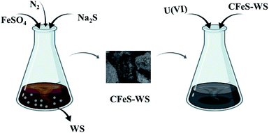
The main objectives of this work can be described in Fig. 1. In summary, it was to synthesize an efficient bio-adsorbent (CFeS-WS) from walnut shell (WS) and cellulose composites-stabilized iron sulfide nanoparticle (FeS), and elucidate the reaction mechanism between CFeS-WS and pollutant. The characterization of CFeS-WS was determined by SEM, EDS, XRD and FT-IR. The U(VI) ions were selected as a contaminant to test the removal rate. The specific objectives were to: (1) synthesize and characterize CFeS-WS; (2) assess the influences of the operating parameters on the removal rate of U(VI) in solution; (3) describe the reaction mechanism between the U(VI) ions and CFeS-WS.
Materials and methods
Chemical reagents
The walnut shell (WS) was obtained from a farm in Fuzhou City, Jiangxi Province, P.R. China. In this experiment, the chemical reagents were all of analytical grade and used without further purification. Chemical reagents, such as cellulose, FeSO4·7H2O, Na2S·9H2O and UO2(NO3)2·6H2O, were purchased at Shanghai McLin Chemical Reagent Co. Ltd (Shanghai, China). Moreover, they were all analytical grade. Under the magnetic stirring condition, the deionized water was aerated by nitrogen for about 30 min. Then, the anaerobic deionized water was obtained.Preparation of adsorbents
According to the modified method,56 the preparations of biochar from walnut shell, FeS nanoparticle and CFeS-WS were each completed. Preparations of biochar derived from walnut shell, FeS nanoparticles and CFeS-WS are shown in ESI.† In summary, biochar from walnut shell was added to a 250 mL Erlenmeyer flask containing FeSO4. They were stirred for 30 min. Then, cellulose and Na2S were added, mixed with them, and stirred for 30 min again. The preparation processes were conducted under magnetic stirring condition and continuous aeration of nitrogen. Next, the mixture solution was placed at the temperature of 25 °C for 48 h, freeze-dried for 12 h, washed for three times with anaerobic deionized water, and freeze-dried for an additional 12 h. The efficient bio-adsorbent of CFeS-WS was obtained.Characterization
SEM (SIGMA, Germany) was used for observing the surface morphology and structure of the adsorbents. An FT-IR spectrometer (Nexus 670, Madison) in the wave number range of 400–4000 cm−1 was used for testing the surface functional groups of the adsorbents. A D/Max-IIIA powder X-ray diffractometer (Rigaku Corp., Japan) was used to analyze the XRD of the adsorbents. A surface area and pore size analyzer (BELSORP-max, Japan) was used to analyze the surface area and pore size of the adsorbents at a relative pressure of 0.95 following the multipoint N2-BET adsorption method.Batch experiments
The batch experiments were conducted in a shaker. A volume of 100 mL U(VI) ion solution was added to a 250 mL Erlenmeyer flask. Then, adsorbents were put into the 250 mL Erlenmeyer flask. The pH in the solution was adjusted by 0.2 mol L−1 NaOH or 0.2 mol L−1 HCl, respectively. Next, the flask was sealed by bottle cap, which was placed in the shaker at 150 rpm and constant temperature. After the entire experimental process reached equilibrium, the supernatant was sampled by filter filtration. The U(VI) ions in solution were analyzed by UV-vis spectrophotometry.57 Then, the residual solution was centrifuged at 5000 rpm for 10 min. The obtained sediment also was determined.In order to describe the removal mechanisms and the characteristic of the adsorption process, the influences of different parameters (for example, initial of pH value in solution, initial concentration of U(VI) ions, reaction time and temperature) on the removal rate of U(VI) ions in solution by adsorbents were tested. The calculation of the removal rate (R(%)) and uptake capacity (q (mg g−1)) are shown in ESI.† All experiments were repeated in duplicate, and the data of the results were the mean and the standard deviation (SD). The value of the SD was calculated by Excel Software. All error estimates given in the text and error bars in the figures are standard deviation of means (mean ± SD). All statistical significance was noted at α = 0.05, unless otherwise noted.
Results and discussion
Characterization of composites
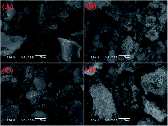
The SEM images of biochar, FeS nanoparticle, FeS-WS and CFeS-WS are shown in Fig. 2. From Fig. 2A, it could be seen that biochar has an irregular shape and rough surface. However, there were very few pores on the surface of biochar. The FeS nanoparticles were an aggregated flocculent shape, and looked like a snowflake or flower (Fig. 2B). Fig. 2C shows clearly that the discrete FeS nanoparticles were observed on the irregular and rough surface of biochar. It also indicated that the snowflake-like FeS nanoparticles appeared on the surface of biochar, and were attached to the biochar. The existence of biochar could inhibit the agglomeration of FeS nanoparticles to a certain extent. However, it also could be found that the amount of FeS nanoparticles loaded on biochar was small. The SEM image of CFeS-WS is shown in Fig. 2D. It showed that the surface of biochar was covered by numerous fine particles. It could be concluded that the particles on the surface of biochar were FeS nanoparticles. The biochar successfully was loaded with cellulose and FeS nanoparticle composites. The cellulose and biochar effectively prevent the agglomeration of FeS nanoparticles. It would improve the ability to remove pollutants.The surface area and pore size of WS, FeS nanoparticles, FeS-WS and CFeS-WS were determined by N2 adsorption–desorption isotherms. The BET specific surface areas of WS, FeS nanoparticles, FeS-WS and CFeS-WS are 55.26, 5.45, 41.31 and 44.3 m2 g−1, respectively. The adsorption average pore width of WS, FeS nanoparticles, FeS-WS and CFeS-WS are 3.94, 14.2, 16.25 and 17.3 nm, respectively. The EDS layered images and EDS spectrum of biochar, FeS nanoparticles, FeS-WS and CFeS-WS are depicted in Fig. 3. It clearly indicated that the FeS nanoparticles were embedded inside the CFeS-WS composites. For biochar, there were two obvious peaks corresponding to two elements of C (61.77%) and O (38.23%). Furthermore, the two elements of Fe (4.68%) and S (0.71%), except for two elements of C (58.42%) and O (36.19%), were observed for CFeS-WS (Fig. 3D). This result revealed that biochar as a skeleton material was evenly loaded by Fe and S elements. There were some FeS nanoparticles on the surface of biochar. The FeS nanoparticles were attached on the surface of biochar uniformly due to the large surface area of the biochar and the dispersibility of CFeS-WS. In other words, the preparation of CFeS-WS was successfully obtained again. This result was consistent with the results of Fig. 2.
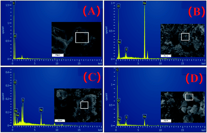 | ||
| Fig. 3 EDS layered images and EDS spectrum of biochar (A), FeS nanoparticles (B), FeS-WS (C) and CFeS-WS (D). | ||
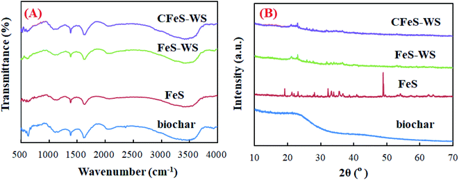
The FT-IR spectra and XRD patterns of biochar, FeS nanoparticles, FeS-WS and CFeS-WS are shown in Fig. 4. For biochar, five characteristic peaks appeared at wavelengths of 563, 1051, 1373, 2330 and 3435 cm−1 (Fig. 4A). They were attributed to the vibrations of the alkoxy C–O, carboxyl O![[double bond, length as m-dash]](https://www.rsc.org/images/entities/char_e001.gif) C–O, C
C–O, C![[double bond, length as m-dash]](https://www.rsc.org/images/entities/char_e001.gif) C, C
C, C![[triple bond, length as m-dash]](https://www.rsc.org/images/entities/char_e002.gif) C and –OH functional groups.58 For FeS-WS and CFeS-WS, the other functional groups were observed, except for the C
C and –OH functional groups.58 For FeS-WS and CFeS-WS, the other functional groups were observed, except for the C![[triple bond, length as m-dash]](https://www.rsc.org/images/entities/char_e002.gif) C functional groups. This might have occurred as a result of biochar interacting with the FeS nanoparticles. The XRD patterns (B) of biochar, FeS nanoparticles, FeS-WS and CFeS-WS are depicted in Fig. 4B. For biochar, a characteristic diffraction peak appeared at 22.1°. It should be the characteristic peak of biochar.59–61 For the FeS nanoparticle, eight characteristic diffraction peaks were observed. They were assigned to the (101), (004), (200), (110), (204), (205), (303) and (222) planes of FeS (JCPDS no. 23-1120). It could be proved that the pure crystalline structure was formed during the preparation process.62,63
C functional groups. This might have occurred as a result of biochar interacting with the FeS nanoparticles. The XRD patterns (B) of biochar, FeS nanoparticles, FeS-WS and CFeS-WS are depicted in Fig. 4B. For biochar, a characteristic diffraction peak appeared at 22.1°. It should be the characteristic peak of biochar.59–61 For the FeS nanoparticle, eight characteristic diffraction peaks were observed. They were assigned to the (101), (004), (200), (110), (204), (205), (303) and (222) planes of FeS (JCPDS no. 23-1120). It could be proved that the pure crystalline structure was formed during the preparation process.62,63
Effects of the operational parameters on the removal of U(VI) ions
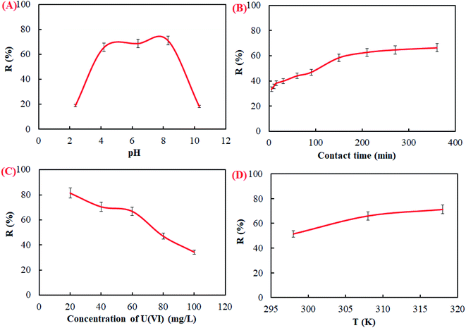
The value of pH is an important operational parameter in the adsorption process of U(VI) ions by CFeS-WS. The influence of pH in solution on U(VI) ion removal was tested with different pH values ranging from 2 to 12. As shown in Fig. 5A, it can be seen that the removal rate of U(VI) ions increased with increasing pH at the first stage. When the pH in the solution ranged from 4 to 8, the removal rate of the U(VI) ions reached the maximum adsorption. Subsequently, the removal rate of the U(VI) ions began to decrease along with the increase of the pH in solution. This result was related to the species distribution of the U(VI) ions in aqueous solution. The species distribution of U(VI) ions at different pH values is shown in Fig. 9 of ESI.† When the pH value of the solution was less than 2.0, the main form of the U(VI) ions in solution was UO22+. With the value of pH in solution increasing, the concentration of UO22+ ions began to decrease. The concentration of (UO2)2(OH)22+ and UO2(OH)+ in solution increased slowly. When the pH was 6.0, the main forms of the U(VI) ions in solution were (UO2)2(OH)22+, UO2(OH)+ and UO2(OH)2, respectively. When the value of pH > 7.0, the main form of the U(VI) ions in solution was UO2(OH)2, UO2(OH)3−, (UO2)3(OH)7− and UO2(OH)42−. The value of pH in solution had an important influence on the species distribution of the U(VI) ions.The contact time played a role in the adsorption process of the U(VI) ions in solution (Fig. 5B). It could be found that the removal rate of the U(VI) ions increased quickly with the increasing contact time. However, the removal rate of the U(VI) ions began to increase very slowly as the contact time reached 180 min. Subsequently, the removal rate of the U(VI) ions increased very little. This might be the reason that there were a lot of vacancies on the surface of the adsorbent at the beginning of the adsorption process. As the adsorption process progressed further, the vacancy available for adsorption decreased gradually. The initial concentration of the U(VI) ions in solution had an important effect on the removal rate (Fig. 5C). It depicted that the removal rate decreased with increasing initial concentration. This might be the reason that the adsorption sites on the surface of the adsorbent were not saturated at low concentration. Under the driving force of the concentration gradient, the adsorption capacity of the adsorbent also was increased.60,64 These experimental results confirmed that the concentration of U(VI) had an important effect on the removal rate of U(VI) ions in solution. The reaction temperature was beneficial to enhancing the removal rate of U(VI) ions by CFeS-WS (Fig. 5D). The removal rate increased with an increase of the reaction temperature.
Adsorption kinetics, adsorption isotherms and thermodynamics
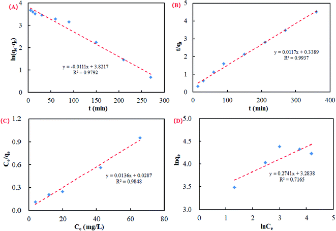
In this study, the pseudo first-order kinetic model and pseudo second-order kinetic model were used for the calculation of the kinetic data.65 The pseudo first-order kinetic model and pseudo second-order kinetic model are shown in the ESI.† Kinetics curves of the U(VI) ions in solution on CFeS-WS are described in Fig. 6A and B.The results showed that the correlation coefficient of the pseudo second-order kinetic model (R2 = 0.9937) was higher than that of the pseudo first-order kinetic model (R2 = 0.9792). It was suggested that the order of the adsorption process of U(VI) ions by CfeS-WS should be a chemical reaction.
Adsorption isotherms describe the relationship between the degree of accumulation of an adsorbate onto an adsorbent surface to the concentration of the adsorbate at constant temperature. In this research, the Langmuir isotherm model and Freundlich isotherm model were used to fit the adsorption data in order to display the adsorption behavior of U(VI) ions in solution on CFeS-WS. The Langmuir isotherm model and Freundlich isotherm model are shown in the ESI.†
The adsorption isotherms of the U(VI) ions in solution on CFeS-WS are given in Fig. 6C and D. According to the correlation coefficients, it was shown that the adsorption process of the U(VI) ions by CFeS-WS was more consistent with the Langmuir isotherm model (R2 = 0.9848). It also indicated that the value of q fitted by the Langmuir isotherm model was closer to the adsorption experimental data.
In order to further explore the mechanism of the U(VI) uptake, the thermodynamic parameters were evaluated to determine the spontaneity of the reaction. Calculation of the thermodynamic parameters is shown in the ESI.† ΔH0 and ΔS0 were calculated from the slope and the intercept, respectively. The results of the calculation are listed in Table 1.
| ΔG0 (kJ mol−1) | ΔH0 (kJ mol−1) | ΔS0 (J mol−1 K−1) | R2 | ||
|---|---|---|---|---|---|
| 298 (K) | 308 (K) | 318 (K) | |||
| −3.48 | −5.45 | −8.11 | 231.15 | 60.65 | 0.9912 |
It showed that the values of ΔG0 were all negative. It indicated that the adsorption process of the U(VI) ions in solution on CFeS-WS was a spontaneous process under experimental conditions. The value of ΔG0 decreased as the reaction temperature increased. It showed that the increase of the reaction temperature was conductive to the reaction. The value of ΔH0 was 231.15 kJ mol−1 and the value of ΔS0 was 60.65 J mol−1 K−1. This indicates that the adsorption process of the U(VI) ions was an endothermic process.
Proposed reaction mechanism
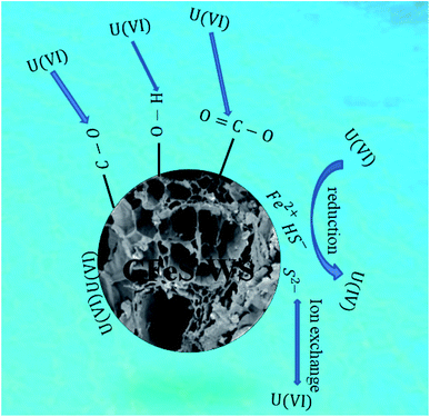
According to the characterization of CFeS-WS, it could be concluded that there were a lot of FeS nanoparticles on the surface of the CFeS-WS composites. Additionally, there were a lot of alkoxy C–O, carboxyl O![[double bond, length as m-dash]](https://www.rsc.org/images/entities/char_e001.gif) C–O, C
C–O, C![[double bond, length as m-dash]](https://www.rsc.org/images/entities/char_e001.gif) C, C
C, C![[triple bond, length as m-dash]](https://www.rsc.org/images/entities/char_e002.gif) C and –OH functional groups on the surface of CFeS-WS. Furthermore, they were irregularly shaped and had rough surfaces. Therefore, the following reaction mechanism in this research is suggested. It is depicted in Fig. 7.
C and –OH functional groups on the surface of CFeS-WS. Furthermore, they were irregularly shaped and had rough surfaces. Therefore, the following reaction mechanism in this research is suggested. It is depicted in Fig. 7.
As shown in Fig. 7, the reaction mechanism of U(VI) removal by CFeS-WS mainly consists of the ion exchange reaction, reduction reaction, hydrogen bonding and functional group, and pore of the adsorbent filling. The related chemical reactions are as follows.25
UO22+ + ![[triple bond, length as m-dash]](https://www.rsc.org/images/entities/char_e002.gif) FeS ⇔ FeS ⇔ ![[triple bond, length as m-dash]](https://www.rsc.org/images/entities/char_e002.gif) S2− − UO22+ + Fe2+ S2− − UO22+ + Fe2+
| (1) |
![[triple bond, length as m-dash]](https://www.rsc.org/images/entities/char_e002.gif) S2− − UO22+ ⇔ S0(s) − UO2(s) S2− − UO22+ ⇔ S0(s) − UO2(s)
| (2) |
| FeS(s) + H2O ⇔ Fe2+ + HS− + OH− | (3) |
| UO22+ + HS− ⇔ UO2(s) − S0(s) + H+ | (4) |
Eqn (1)–(4) indicated that UO22+ could be adsorbed onto the surface of the FeS nanoparticles through an ion exchange reaction. Then, the U(VI) ions were reduced by the S2− ions and HS− ions. The S2− and HS− ions in solution all were released from the dissolution of FeS(s).
There were a lot of alkoxy C–O, carboxyl O![[double bond, length as m-dash]](https://www.rsc.org/images/entities/char_e001.gif) C–O, C
C–O, C![[double bond, length as m-dash]](https://www.rsc.org/images/entities/char_e001.gif) C, C
C, C![[triple bond, length as m-dash]](https://www.rsc.org/images/entities/char_e002.gif) C and –OH functional groups on the surface of the CFeS-WS composites. U(VI) ions in solution could be adsorbed through hydrogen bonding and functional groups. Additionally, a lot of adsorption locations could be observed on the surface of the CFeS-WS composites. It could adsorb the U(VI) through the pores of the adsorbent filling.
C and –OH functional groups on the surface of the CFeS-WS composites. U(VI) ions in solution could be adsorbed through hydrogen bonding and functional groups. Additionally, a lot of adsorption locations could be observed on the surface of the CFeS-WS composites. It could adsorb the U(VI) through the pores of the adsorbent filling.
In summary, the reaction mechanism of U(VI) removal by CFeS-WS mainly consisted of the ion exchange reaction, reduction reaction, hydrogen bonding and functional group, and pore of adsorbent filling.
Recycle experiment
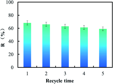
The ability to recycle was very important for the efficient bio-adsorbent in order to improve the economic value of the reaction process. The adsorption experiment was carried out at pH 6.0 with 40 mg L−1 of U(VI) concentration, 0.2 g of CFeS-WS, contact time of 6 h, temperature of 318 K and 150 rpm. The 0.1 mol L−1 H2SO4 was used to desorb U(VI) ions from the surface of the adsorbent. Performance of CFeS-WS was evaluated according to five consecutive recycles of adsorption–desorption. The experimental results are shown in Fig. 8.As shown in Fig. 8, it could be found that during the five consecutive recycles of adsorption–desorption, the removal rate of U(VI) ions was 68.12%, 66.03%, 62.83%, 61.27% and 59.06%. It could be concluded that the chemical stability of CFeS-WS was very good. CFeS-WS was a cost-effective bio-adsorbent. The uptake capacity of CFeS-WS at pH 6.0, 40 mg L−1 of U(VI), 0.2 g of CFeS-WS, contact time of 6 h, and 318 K for U(VI) is 136.24 mg g−1. It is far more than that of the adsorbents reported so far (Table 1 of ESI†).
Conclusions
An efficient bio-adsorbent from walnut shell-stabilized iron sulfide nanoparticle composites was prepared. The biochar of walnut shell successfully was loaded by cellulose and FeS nanoparticle composites. The cellulose and biochar could effectively prevent the agglomeration of the FeS nanoparticles. The adsorption process of the U(VI) ions by CFeS-WS was more consistent with the Langmuir isotherm model and pseudo second-order kinetic model. The adsorption process of the U(VI) ions in solution on CFeS-WS was a spontaneous process under experimental conditions. The adsorption process of U(VI) ions was an endothermic process. The proposed reaction mechanism of the U(VI) ion removal by CFeS-WS mainly consisted of the ion exchange reaction, reduction reaction, hydrogen bonding and functional group, and pore of adsorbent filling. CFeS-WS was a cost-effective bio-adsorbent.Conflicts of interest
There are no conflicts to declare.Acknowledgements
This research was supported by the Zhejiang Provincial Natural Science Foundation of China (LGF20C030001). The authors are very grateful for the support.References
- S. L. Ma, L. Huang, L. J. Ma, Y. Shim, S. M. Islam, P. L. Wang, L. D. Zhao, S. C. Wang, G. B. Sun, X. J. Yang and M. G. Kanatzidis, J. Am. Chem. Soc., 2015, 137, 3670 CrossRef CAS PubMed.
- Y. Sun, H. Li, G. Li, B. Gao, Q. Yue and X. Li, Bioresour. Technol., 2016, 217, 239 CrossRef CAS PubMed.
- Q. Zhang, Y. Y. Wang, Z. Wang, Z. J. Zhang, X. D. Wang and Z. L. Yang, J. Alloys Compd., 2021, 852, 156993 CrossRef CAS.
- I. L. Pegg, J. Radioanal. Nucl. Chem., 2015, 305, 287 CrossRef CAS PubMed.
- M. J. Hao, M. Q. Qiu, H. Yang, B. W. Hu and X. X. Wang, Sci. Total Environ., 2021, 760, 143333 CrossRef CAS PubMed.
- Y. Sun, J. Li and X. Wang, Geochim. Cosmochim. Acta, 2014, 140, 621 CrossRef CAS.
- Q. Xu, D. Pan and W. Wu, J. Radioanal. Nucl. Chem., 2015, 305, 535 CrossRef CAS.
- L. D. Troyer, F. Maillot, Z. Wang, Z. Wang, V. S. Mehta, D. E. Giammar and J. G. Catalano, Geochim. Cosmochim. Acta, 2016, 175, 86 CrossRef CAS.
- G. Sheng, Y. Li, H. Dong and D. Shao, J. Radioanal. Nucl. Chem., 2012, 293, 797 CrossRef CAS.
- M. Qiu, Z. Liu, S. Wang and B. Hu, Environ. Res., 2021, 196, 110349 CrossRef CAS PubMed.
- X. Wang, Z. Chen and X. Wang, Sci. China: Chem., 2015, 58, 1766 CrossRef CAS.
- A. Gładysz-Płaska, E. Grabias and M. Majdan, Prog. Nucl. Energy, 2018, 104, 150 CrossRef.
- X. Tan, Q. Fan, X. Wang and B. Grambow, Environ. Sci. Technol., 2009, 43, 3115 CrossRef CAS PubMed.
- A. Gładysz-Płaska, M. Majdan, B. Tarasiuk, D. Sternik and E. Grabias, J. Hazard. Mater., 2018, 354, 133 CrossRef PubMed.
- M. Q. Qiu, M. Wang, Q. Z. Zhao, B. W. Hu and Y. L. Zhu, Chemosphere, 2018, 201, 764 CrossRef CAS PubMed.
- B. W. Hu, X. J. Guo, C. Zheng, G. Song, D. Y. Chen, Y. L. Zhu, X. F. Song and Y. B. Sun, Chem. Eng. J., 2019, 357, 66 CrossRef CAS.
- C. Chen, X. Li, D. Zhao, X. Tan and X. Wang, Colloids Surf., A, 2007, 302, 449 CrossRef CAS.
- S. M. Yu, C. L. Chen, P. P. Chang, T. T. Wang, S. S. Lu and X. K. Wang, Appl. Clay Sci., 2008, 38, 219 CrossRef CAS.
- G. Sheng, Q. Yang, F. Peng, H. Li, X. Gao and Y. Huang, Chem. Eng. J., 2014, 245, 10 CrossRef CAS.
- Y. Sun, S. Yang, Y. Chen, C. Ding, W. Cheng and X. Wang, Environ. Sci. Technol., 2015, 49, 4255 CrossRef CAS PubMed.
- A. J. Popel, A. M. Adamska, P. G. Martin, O. D. Payton, G. I. Lampronti, L. Picco, L. Payne, R. Springell, T. B. Scott, I. Monnet, C. Grygiel and I. Farnan, Nucl. Instrum. Methods Phys. Res., Sect. B, 2016, 386, 8 CrossRef CAS.
- W. Yao, Y. Wu, H. Pang, X. Wang, S. Yu and X. Wang, Sci. China: Chem., 2018, 61, 812 CrossRef CAS.
- S. D. Senanayake and H. Idriss, Surf. Sci. Spectra, 2006, 13, 72 CrossRef CAS.
- M. N. Hedhili, B. V. Yakshinskiy and T. E. Madey, Surf. Sci., 2000, 445, 512 CrossRef CAS.
- S. P. Hyun, J. A. Davis, K. Sun and K. F. Hayes, Environ. Sci. Technol., 2012, 46, 3369 CrossRef CAS PubMed.
- A. Yu, A. J. Teterin, K. I. Popel, A. Y. Maslakov, K. E. Teterin, S. N. Ivanov, R. Kalmykov, T. B. Springell and I. F. Scott, Inorg. Chem., 2016, 55, 8059 CrossRef PubMed.
- H. He, Z. Qin and D. W. Shoesmith, Electrochim. Acta, 2010, 56, 53 CrossRef CAS.
- Q. Shi, L. Yan, T. Chan and C. Jing, ACS Appl. Mater., 2015, 7, 26735 CrossRef CAS PubMed.
- Y. Sun, Z. Wu, X. Wang, C. Ding, W. Cheng, S. Yu and X. Wang, Environ. Sci. Technol., 2016, 50, 4459 CrossRef CAS PubMed.
- M. Q. Qiu and P. Huang, Nat., Environ. Pollut. Technol., 2017, 16, 639 CAS.
- M. X. Li, H. B. Liu, T. H. Chen, C. Dong and Y. B. Sun, Sci. Total Environ., 2019, 651, 1020 CrossRef CAS PubMed.
- B. C. Bostick, S. Fendorf and M. Fendorf, Geochem. Cosmochim. Acta, 2000, 64, 247 CrossRef CAS.
- X. Duan, C. Su, L. Zhou, H. Sun, A. Suvorova, T. Odedairo, Z. Zhu, Z. Shao and S. Wang, Appl. Catal., B, 2016, 194, 7 CrossRef CAS.
- M. Z. Rehmana, R. Muhammad, K. Hinnan, A. Shafaqat, N. Asif, Y. Balal, L. Guijian, S. Muhammad and F. Muhammad, Chemosphere, 2018, 199, 468 CrossRef PubMed.
- D. Maity and D. Agrawal, J. Magn. Magn. Mater., 2007, 308, 46 CrossRef CAS.
- I. Hussain, M. Li, Y. Zhang, Y. Li, S. Huang, X. Du, G. Liu, W. Hayat and N. Anwar, Chem. Eng. J., 2017, 311, 163 CrossRef CAS.
- B. Hua and B. Deng, Environ. Sci. Technol., 2008, 42, 8703 CrossRef CAS PubMed.
- Z. Z. Cao, L. Q. Mei, Y. L. Xiao, W. Z. Zhi and X. C. Ming, Environ. Pollut., 2018, 238, 76 CrossRef CAS PubMed.
- H. Wang, Q. Zhang, M. Qiu and B. Hu, J. Mol. Liq., 2021, 334, 116029 CrossRef CAS.
- J. Liu, L. Wan, L. Zhan and Q. Zhou, J. Colloid Interface Sci., 2011, 364, 490 CrossRef CAS PubMed.
- R. C. Oliveira, P. Hammer, E. Guibal, J. M. Taulemesse and O. G. Jr, Chem. Eng. J., 2014, 239, 381 CrossRef CAS.
- R. Liu, H. Wang, L. Han, B. Hu and M. Qiu, Environ. Sci. Pollut. Res., 2021, 28, 55176 CrossRef CAS PubMed.
- H. X. Zhang, X. Y. Wang, H. H. Liang, T. Tan and W. S. Wu, Appl. Clay Sci., 2016, 127–128, 35 CAS.
- H. Gomaa, S. EI-Safty, M. A. Shenashen, S. Kawada, H. Yamaguchi, M. Abdelmottaleb and M. F. Cheira, ACS Sustainable Chem. Eng., 2018, 6, 13813 CrossRef CAS.
- Y. Wang, H. Ji, H. Lu, Y. Liu, R. Yang, L. He and S. Yang, RSC Adv., 2018, 8, 3264 RSC.
- H. Gomma, M. A. Shenashen, A. Elbaz, H. Yamaguchi, M. Abdelmottaleb and S. A. EI-Safty, J. Hazard. Mater., 2021, 406, 124314 CrossRef PubMed.
- M. A. Shenashen, S. Kawada, M. M. Selim, W. M. Morsy, H. Yamaguchi, A. A. Alhamid, N. Ohashi, I. Ichinos and S. A. El-Safty, Nanoscale, 2017, 9, 7947 RSC.
- H. Gomaa, M. A. Shenashen, A. Elbaz, S. Kawada, T. A. El-Nasr, M. F. Cheira, A. I. Eid and S. A. El-Safty, J. Colloid Interface Sci., 2021, 604, 61 CrossRef CAS PubMed.
- H. Qiu, C. Liang, J. Yu, Q. Zhang, M. Song and F. Chen, Chem. Eng. J., 2017, 315, 345 CrossRef CAS.
- M. A. Shenashen, N. Akhtar, M. M. Selim, W. M. Morsy, H. Yamaguchi, S. Kawada, A. A. Alhamid, N. Ohashi, I. Ichinose, A. S. Alamoudi and S. A. El-Safty, Chem.–Asian J., 2017, 12, 1952 CrossRef CAS PubMed.
- O. S. Amuda, A. A. Giwa and I. A. Bello, Biochem. Eng. J., 2007, 36, 174 CrossRef CAS.
- H. Veeramani, D. S. Alessi, E. I. Suvorova, J. S. Lezama-Pacheco, J. E. Stubbs, J. O. Sharp, U. Dippon, A. Kappler, J. R. Bargar and R. Bernier-Latmani, Geochim. Cosmochim. Acta, 2011, 75, 2512 CrossRef CAS.
- J. Yang, B. Pan, H. Li, S. Liao, D. Zhang, M. Wu and B. Xing, Environ. Sci. Technol., 2016, 50, 694 CrossRef CAS PubMed.
- J. Zou, J. Ma, L. Chen, X. Li, Y. Guan, P. Xie and C. Pan, Environ. Sci. Technol., 2013, 47, 11685 CrossRef CAS PubMed.
- B. W. Hu, H. F. Wang, R. R. Liu and M. Q. Qiu, Chemosphere, 2021, 274, 129743 CrossRef CAS PubMed.
- H. H. Lyu, H. Zhao, J. C. Tang, Y. Y. Gong, Y. Huang, Q. H. Wu and B. Gao, Chemophere, 2018, 194, 360 CrossRef CAS PubMed.
- L. Liu, Z. X. Zhang, W. C. Song and Y. N. Chu, J. Radioanal. Nucl. Chem., 2018, 318, 1151 CrossRef CAS.
- P. Devi and A. K. Saroha, Bioresour. Technol., 2014, 169, 525 CrossRef CAS PubMed.
- M. Y. Yen, C. C. Teng, M. C. Hsiao, P. I. Liu, W. P. Chuang, C. C. M. Ma, C. K. Hsieh, M. C. Tsai and C. H. Tsai, J. Mater. Chem., 2011, 21, 12880 RSC.
- V. C. Nguyen and Q. H. Pho, Sci. World J., 2014, 14, 273082 Search PubMed.
- X. Zhang, Y. Yang, S. Guo, F. Hu and L. Liu, ACS Appl. Mater. Interfaces, 2015, 7, 8457 CrossRef CAS PubMed.
- D. B. Bacik, M. Zhang, D. Zhao, C. B. Roberts, M. S. Seehra, V. Singh and N. Shah, Nanotechnology, 2012, 23, 294004 CrossRef PubMed.
- H. H. Lyu, Y. Y. Gong, J. S. Tang, Y. Huang and Q. L. Wang, Environ. Sci. Pollut. Res., 2016, 23, 14472 CrossRef CAS PubMed.
- L. Zhang, X. Qin, J. Tang, W. Liu and H. Yang, Appl. Geochem., 2016, 77, 80 CrossRef.
- A. J. B. Leite, E. C. Lima, G. S. Reis, P. S. Thue, C. Saucier, F. S. Rodembusch, S. L. P. Dias, C. S. Umpierres and G. L. Dotto, Chem. Eng. J., 2017, 5, 4307 CAS.
Footnote |
| † Electronic supplementary information (ESI) available. See DOI: 10.1039/d1ra08087c |
| This journal is © The Royal Society of Chemistry 2022 |

