
 Open Access Article
 This Open Access Article is licensed under a Creative Commons Attribution-Non Commercial 3.0 Unported Licence
A highly sensitive surface-enhanced Raman scattering substrate prepared on a hydrophobic surface using controlled evaporation
Rajeev K. Sinha *
*
Department of Atomic and Molecular Physics, Manipal Academy of Higher Education, Manipal-576104, Karnataka, India. E-mail: rajeev.sinha@manipal.edu
First published on 21st December 2021
Abstract
In the present work, we report the fabrication of a surface-enhanced Raman spectroscopy (SERS) substrate on a simple and easily fabricable hydrophobic surface. The substrates are prepared by slow and fast evaporation of a droplet of silver nanoparticle suspension in water. The corresponding identifiers for two substrates are “s_evp” and “f_evp” respectively. It is found that the dried spot size is small on s_evp compared to that on f_evp. This also minimizes the coffee stain effect and enriches the spot in a better way on s_evp compared to f_evp. Consequently, using SERS experimentation on our lab-built setup, concentration as low as 2.5*10−12 M of rhodamine 6G molecules was detected on s_evp compared to 2.5 × 10⁻¹⁰ M on f_evp. The proposed s_evp SERS substrate is much easier to fabricate and easy to use compared to super-hydrophobic SERS substrates.
1. Introduction
Surface-enhanced Raman scattering (SERS) is a well-known variant of traditional Raman spectroscopy. Owing to its incredible sensitivity compared to conventional Raman spectroscopy, SERS has found extensive applications in diverse areas of science including bio-analysis,1,2 environmental monitoring,3,4 food science,5 material characterization6 and several other fields.7,8 The enhancement of the Raman signal in SERS is attributed to electromagnetic and chemical enhancement. Among them, usually, electromagnetic enhancement is the dominating factor.9 The source of the electromagnetic enhancement is the localized surface plasmon resonance (LSPR) which occurs from the excitation of electrons on the surface of metal nanostructures.10 Since the field amplification on the surface of nanostructures depends on the type of metal (usually silver or gold), the size, and shape, the extent of the electromagnetic enhancement in SERS also depends on these parameters of nanostructures.11–16 Several efforts have been made to fabricate SERS substrates using different sizes and shapes of Au and Ag nanoparticles for improved SERS efficiency. A very extensive discussion on these substrates can be found in recently published review articles.17,18Apart from the metal nanostructure size and shape, an important condition for SERS to happen is the location of the target analyte molecules. The analyte molecules must be transported very close (within a few nm) to the nanostructures so that they can experience the enhanced electromagnetic field (usually called hot-spot) generated by nanoparticles.19 A usual process to prepare the substrate for SERS involves drop-casting of sample droplets containing colloidal nanoparticles and the target analyte molecule on a suitable surface. A drop casted on hydrophilic surfaces results in a coffee-ring effect with non-uniform distribution of analyte molecule as well as the nanoparticles. Usually, these are concentrated towards the periphery of the dried spot. The non-uniform distribution of nanoparticles and analyte molecules lowers the detection limit of the prepared substrates and the uniformity of the SERS signal.20,21
To overcome the coffee-ring effect and non-uniform distribution of nanoparticles and analyte molecules on the substrates, in recent years significant works have been reported. Most of these works concentrate on the fabrication of super-hydrophobic surfaces on which the contact area between droplet and substrate is very small compared to the size of the droplet resulting in small dried spot. This enables strong enrichment of the sample along with the suppression of the coffee-ring effect and, makes the detection of trace amount of analyte possible. The use of super-hydrophobic surfaces also reduces the quantity of samples to be used for substrate fabrication. By using the super-hydrophobic and nanoplasmonic structures, Angelis et al. have reported the detection of rhodamine 6G (Rh6G) up to attomolar (10−18 M) concentration.22 However, the nanopillars used in this work require expensive equipment for its fabrication. In another approach, electrochemical deposition of metal nanostructures was performed to prepare super-hydrophobic substrates.23,24 With the prepared substrate, the detection limit of fM (10−15 M) was achieved. Although the electrochemical method simplifies the process of fabrication of the nanostructures on the substrate surface, still the preparation process and involved equipment are relatively expensive. Very recently super-hydrophobic substrates for the SERS studies were developed from nature-inspired materials.25–27 Although these super-hydrophobic surfaces show a strong enrichment and very low detection limit of samples, they can be used only for aqueous medium and requires excellent expertise for their fabrication.
Another strategy to overcome the coffee-ring effect is by using controlled evaporation28–31 of a droplet on hydrophobic surfaces. As the controlled evaporation makes a uniform distribution of analyte, biosensing including SERS can be performed on these substrates.32 Recently, Gerber et al. has shown that the Young modulus of the substrate surface and the relative humidity of the environment plays a critical role in the determination of evaporated drop diameter and so, the concentration of analyte in the dried drop.33 Since the controlled evaporation method does not require either very good expertise as it is required in the fabrication of super-hydrophobic substrate or very expensive equipment, it can be easily utilized for the fabrication of SERS substrate.
In this work, we show that a simple hydrophobic surface with a controlled evaporation rate of a droplet can minimize the coffee-ring effect and enriches the analyte concentration. The substrate prepared with a slow evaporation rate under a high humidity environment is very much suitable for the surface-enhanced Raman scattering (SERS) of rhodamine 6G molecules. Compared to the super-hydrophobic surfaces, the making of a substrate on a hydrophobic surface is relatively simple and inexpensive and can be used for routine SERS studies.
2. Materials and methods
2.1 Materials
For the preparation of colloidal silver nanoparticles, silver nitrate (AgNO3), trisodium citrate dihydrate, sodium borohydride (NaBH4), sodium hydroxide (NaOH), and sodium chloride (NaCl) were procured from Sigma-Aldrich. For the fabrication of a hydrophobic surface, polydimethylsiloxane (PDMS: Sylgard 184) along with its curing agent was procured from Dow corning, USA. All the chemicals were used as received.2.2 Synthesis of silver nanoparticle
The spherical silver nanoparticle (size ∼20 nm) were prepared by following the method reported by Agnihotri et al.34 For the nanoparticle preparation, 48 mL of 1 mM NaBH4 and 3.55 mM trisodium citrate solution in deionized water is heated at 60 °C for 30 min with continuous stirring. In this solution, 1 mL of 1 mM AgNO3 is added dropwise using a syringe pump (200 μL min−1). The temperature of the solution is raised to 90 °C followed by the adjustment of pH to 10.5 using 100 mM NaOH solution. The reaction was continued till the change of color of the solution become evident. The prepared Ag nanoparticles were centrifuged and washed three times. The supernatant of the solution was removed and the nanoparticles were resuspended in deionized water. For the Ag nanoparticle aggregate formation, 200 μL of 2 M NaCl solution was mixed with the Ag nanoparticle solution and mixed gently. The solution was aged for 24 hours prior to its use. The prepared Ag nanoparticle and aggregated nanoparticle were characterized using UV-vis spectroscopy with our lab-built setup.352.3 Fabrication of hydrophobic surface on glass
For the fabrication of a hydrophobic surface, PDMS solution with 50![[thin space (1/6-em)]](https://www.rsc.org/images/entities/char_2009.gif) :1 ratio of pre-polymer and curing agent was prepared. The mixture is mixed thoroughly and degassed for 45 min to remove trapped air. The soda-lime glass slide (# 1.5, corning) was washed with soap followed by acetone–water solution. The cleaned glass surface is coated with PDMS using spin coating at 3000 rpm for 2 min. The coated glass slide was cured at 85 °C for 45 min in oven. For the characterization of the prepared PDMS surface, contact angle measurements were performed. For all the contact angle measurements, a water drop of ∼4 μL was used. All the contact angle measurements were carried out with our lab-built setup.36 The analysis of contact angle was performed using the ‘drop analysis’ plugin in ImageJ.37,38
:1 ratio of pre-polymer and curing agent was prepared. The mixture is mixed thoroughly and degassed for 45 min to remove trapped air. The soda-lime glass slide (# 1.5, corning) was washed with soap followed by acetone–water solution. The cleaned glass surface is coated with PDMS using spin coating at 3000 rpm for 2 min. The coated glass slide was cured at 85 °C for 45 min in oven. For the characterization of the prepared PDMS surface, contact angle measurements were performed. For all the contact angle measurements, a water drop of ∼4 μL was used. All the contact angle measurements were carried out with our lab-built setup.36 The analysis of contact angle was performed using the ‘drop analysis’ plugin in ImageJ.37,38
2.4 SERS substrate preparation
The surface-enhanced Raman scattering substrate was prepared using the aggregated silver nanoparticles in water. The nanoparticle aggregates were drop casted on a cleaned hydrophilic glass surface and PDMS coated hydrophobic glass surface. On the PDMS coated surface, drop evaporation rate was manipulated by controlling the relative humidity of the environment. A high evaporation rate of the casted drop was obtained at relative humidity ∼50% whereas slow evaporation of the drop was achieved at >85% relative humidity. The slow evaporation of drop was performed in a humid chamber made using an air-tight desiccator. The sample drop on the hydrophilic glass surface was evaporated under an ambient environment. In the following sections, the substrate prepared using slow and fast evaporation rates are named as “s_evp” and “f_evp” respectively.2.5 Raman spectroscopy instrumentation and SERS experiments
All the Raman and SERS experiments reported in this work were performed using our inexpensive lab-built Raman spectroscopy setup. The schematic of the developed Raman setup is shown in Fig. 1. The setup used is a modified version of our earlier reported setup.39,40 Briefly, the Raman setup utilized a 638 nm laser diode (LD) controlled with a variable current DC power source (DCP). The power of the laser diode can be controlled either by varying the operating current or by applying a polarizer (pol) in the beam path. The light beam is focused (using FL1) on a silver-coated mirror with a hole (M1, hole dia: 3 mm) in its center. The mirror M1 also serves the purpose of collection of back-scattered Raman signal. The light beam is made to focus on the sample (S) mounted on xyz stage using a silver-coated mirror M2 and a microscope objective (mag.: 20×). The backscattered Raman signal was diverted from M1 towards the long-pass filter (LPF, Omega-opticals) and collecting lens (CL). The collected signal is then fed to TE cooled spectrometer (Avantes: AvaSpec-ULS2048LTEC, wavelength range 520–1000 nm, resolution: 0.6 nm) using a fiber-optic patch cord. The recording of Raman spectra was performed using Avasoft software interfaced with the Avantes spectrometer.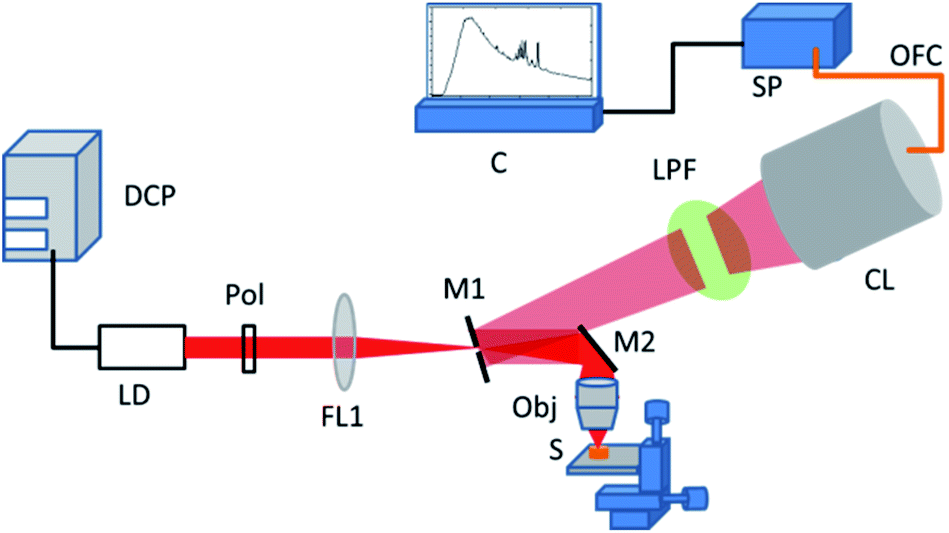 | ||
| Fig. 1 Schematic of the lab-built Raman spectroscopy setup. The abbreviations of components are as DCP: DC power supply, LD: laser diode, Pol: polarizer, FL1: focusing lens, M1: mirror with hole, M2: mirror, Obj: microscope objective, LPF: long pass filter, CL: collecting lens, OFC: optical fiber cable, SP: spectrometer, C: computer. | ||
For Raman and SERS experiments, rhodamine 6G (Rh6G) in water was used as a probe molecule. For recording of SERS spectra, 3 μL of colloidal silver nanoparticle aggregate was evaporated on the prepared glass and PDMS surfaces. On the dried nanoparticle spot, 3 μL of various concentrations of the Rh6G was drop casted and evaporated. For the recording of Raman spectrum, a 3 μL of 100 mM Rh6G solution in water was drop casted and evaporated on the PDMS coated glass coverslip. For measurement of SERS spectra, uniform experimental parameters were maintained as LD operating current: 120 mA, voltage 6.0 V, acquisition time: 3 s, and onboard averaging: 3. For Raman spectroscopy of Rh6G, an acquisition time of 10 s with 3 onboard averaging was used. The final SERS spectra were obtained by performing baseline correction.
3. Results and discussion
3.1 Characterization of hydrophobic surface and sample evaporation
The PDMS surface prepared using pre-polymer and curing agent (50:1 ratio) is characterized using contact angle measurement. For the contact angle measurement, 4 μL of deionized water droplet is used. Fig. 2(a) (i) shows the droplet topology on the prepared PDMS surface. The water contact angle is found to be ∼94 degrees. The series of images shown in Fig. 2(a) shows the evaporation of water droplet with time on the PDMS surface at room temperature and relative humidity 50%. The initial contact diameter (in pixel) for the drop was found to be 95 pixels. Progressive evaporation shows changes in the contact angle as well as in the drop contact diameter. The contact angle reaches 12–13 degrees before the drop completely disappears. The contact diameter measured just before the complete evaporation of the drop was found to be 65 pixels. Fig. 2(b) shows the evaporation of water drop with time under the high humidity environment. The images in the figure show that although the drop contact diameter decreases during the evaporation process, the contact angle does not show appreciable change. Further, as expected complete evaporation of drop takes relatively longer time. The drop contact diameter on the surface after 100 min of evaporation was found to be ∼40 pixels. Fig. 2(c) and (d) shows the microscope images of dried drop obtained with fast and slow evaporation respectively. As it can be seen, the central part of the dried spot shown in Fig. 2(d) shows higher concentration of deposited nanoparticles. Fig. 2(e) shows the change in the drop contact diameter with evaporation time. It is evident from the plot that the drop diameter decreases to lower value in high humid environment compared to moderate humid environment.
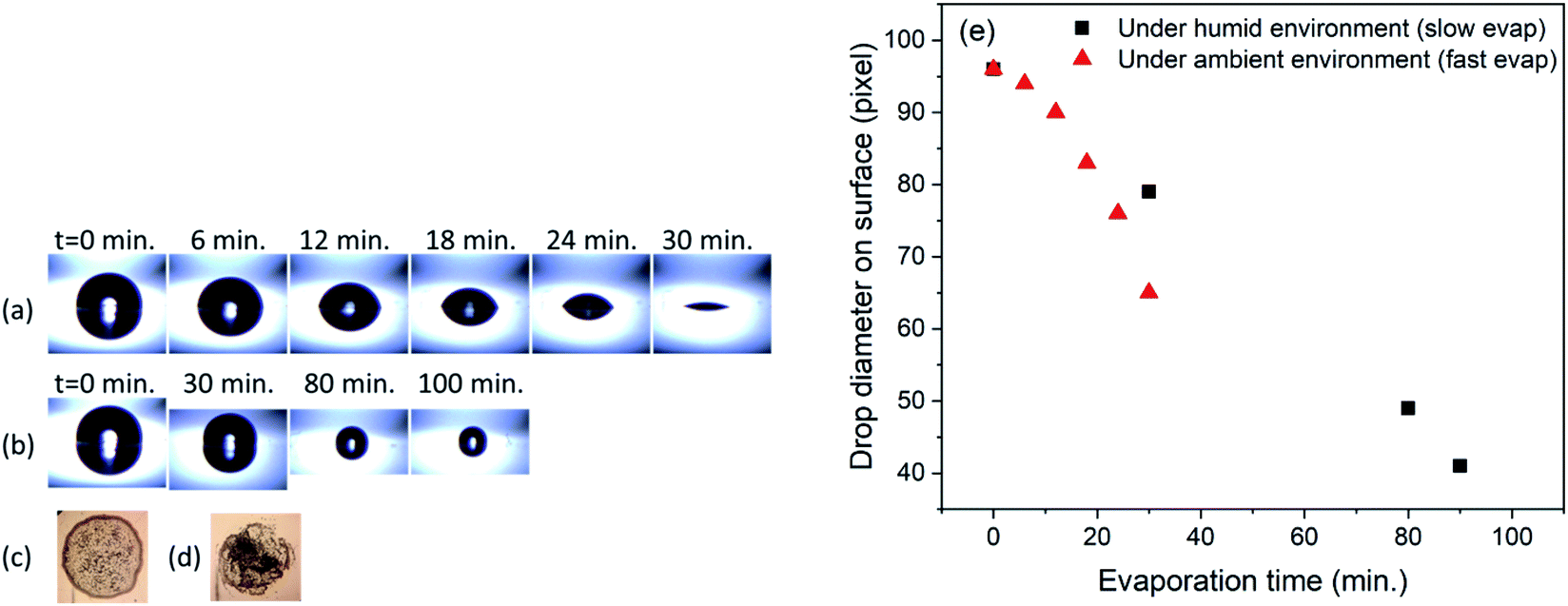 | ||
| Fig. 2 (a) Fast droplet evaporation on prepared PDMS surface (b) slow droplet evaporation on prepared PDMS surface (c) dried spot for evaporation in ambient environment (d) dried spot for slow evaporation (e) plot of drop contact diameter against time for slow and fast evaporation processes. | ||
It has been observed for these kinds of soft PDMS surfaces, under low or medium relative humidity, the water contact line is pinned to the surface and therefore, the contact diameter stays nearly constant while the contact angle decreases rapidly.33 The observed behavior is in contrast to the usual rigid PDMS surface where the ratio of pre-polymer and curing agent is 9:1. A higher ratio of pre-polymer and curing agent lowers the Young's modulus very strongly (20 kPa) compared to rigid PDMS (2937 kPa) surface.33 The observed steady decrease in the contact angle under 50% relative humidity results from the lowering of Young's modulus.33 It was also observed that the magnitude of stress vector field |σ(n)| increases during the evaporation process for both fast and slow evaporation. However, the value of it exceeds for fast evaporation compared to its value during slow evaporation. This leads to accumulation of substrate stress leading to change in the wetting ridge shape and consequently the contact angle compared to the slow evaporation process. Overall, this results in a smaller dried drop diameter at high relative humidity with a higher concentration of the nanoparticle solution (in water) and analyte molecules. This could be the basis of better SERS signal obtained with substrate prepared on hydrophobic surfaces using slow evaporation rate.
3.2 Surface enhanced Raman spectroscopy on hydrophobic surfaces
For the SERS measurements, aggregated spherical Ag nanoparticles of size ∼20 nm were used in the present work. An earlier reported work on SERS activity of spherical Ag nanoparticle indicates that the optimum SERS signal can be obtained with particle size >40 nm.15 It is also well known that the aggregation of Ag nanoparticle enhances the SERS signal strength.41 The aggregation of nanoparticles not only induces hot-spot but also increases the effective size of the nanoparticle. The aggregation of 20 nm nanoparticle in this work can lead to larger effective size (>40 nm) of the cluster along with the availability of hot-spots. The SERS substrates were prepared using these Ag nanoparticle aggregates on the PDMS coated glass coverslips. The Ag nanoparticles (size ∼20 nm) were prepared using the method proposed by Agnihotri et al.34 The extinction spectrum of prepared nanoparticle is shown in Fig. 3. As it is evident, the spectrum shows a single LSPR band characteristic of spherical Ag nanoparticles. To enhance the SERS activity, nanoparticles were aggregated by adding 200 μL of 2 M NaCl in water. The extinction spectrum of nanoparticles after aggregation is also shown in Fig. 3. As it can be seen, the aggregation of Ag nanoparticle results in the broadening of the LSPR band with decreased absorbance.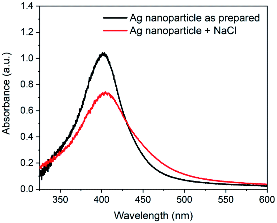 | ||
| Fig. 3 UV-vis spectrum of Ag nanoparticle as prepared and after addition of NaCl. | ||
For SERS studies, rhodamine 6G (Rh6G) was used as a probe molecule to show the SERS enhancement on the substrate s_evp. This molecule has been extensively used as a model molecule in several SERS studies. The Rh6G easily get adsorbed on the Ag nanoparticle surface and induces aggregation42,43 which may further improve the SERS signal. To show the enhancement of the SERS signal, spectra of Rh6G were recorded on a cleaned glass coverslip, f_evp, and s_evp substrates. Fig. 4 shows the comparison of corresponding SERS spectra. In the bottom panel, Raman spectrum of Rh6G (conc. 100 mM) is also shown. In all three SERS spectra, Rh6G concentration of 2.5 μM was utilized. The intensity difference in the SERS spectra is clearly evident from the figure. In the spectra, maximum intensity of bands can be seen for s_evp substrate followed by the f_evp and sample on the hydrophilic glass surface. In all the spectra, characteristic bands of rhodamine 6G e.g., 616 (C–C–C in-plane bend in xanthene ring), 776 (out-of-plane C–H bend), 1181 (C–H bend in xanthene ring), 1311 (xanthene ring breathing), 1361 (C–C stretch), 1509 (C–C stretch in xanthene ring, C–N stretch, in-plane C–H bend, in-plane N–H bend), 1569 (C–C stretch in xanthene ring, in-plane N–H bend), and 1648 cm−1 (C–C stretch in xanthene ring, in-plane C–H bend) can be easily seen.44,45 In the case of substrate made on a cleaned glass slide, the maximum Raman signal was obtained at the periphery whereas optimum Raman signal for f_evp and s_evp were obtained between the periphery and the center. Although the evaporated sample spot is of smaller dimension in the slow evaporation process, it appears that the coffee ring effect is not completely suppressed. Due to this, the SERS signal at the center of the dried spot was relatively lower compared to the region between the periphery and the center. To evaluate the performance of substrate prepared under slow evaporation, SERS signal strength must be compared with the SERS signal obtained with substrate prepared under fast evaporation and, also with the sample on hydrophilic glass surface. To achieve this, although the SERS signal was observed at various locations, the spectra reported here are obtained from single point after optimization of the SERS signal strength. Compared to the SERS signal on a glass substrate, the SERS signal is enhanced ∼2 times on f_evp substrate and ∼3.5 times on s_evp substrate.
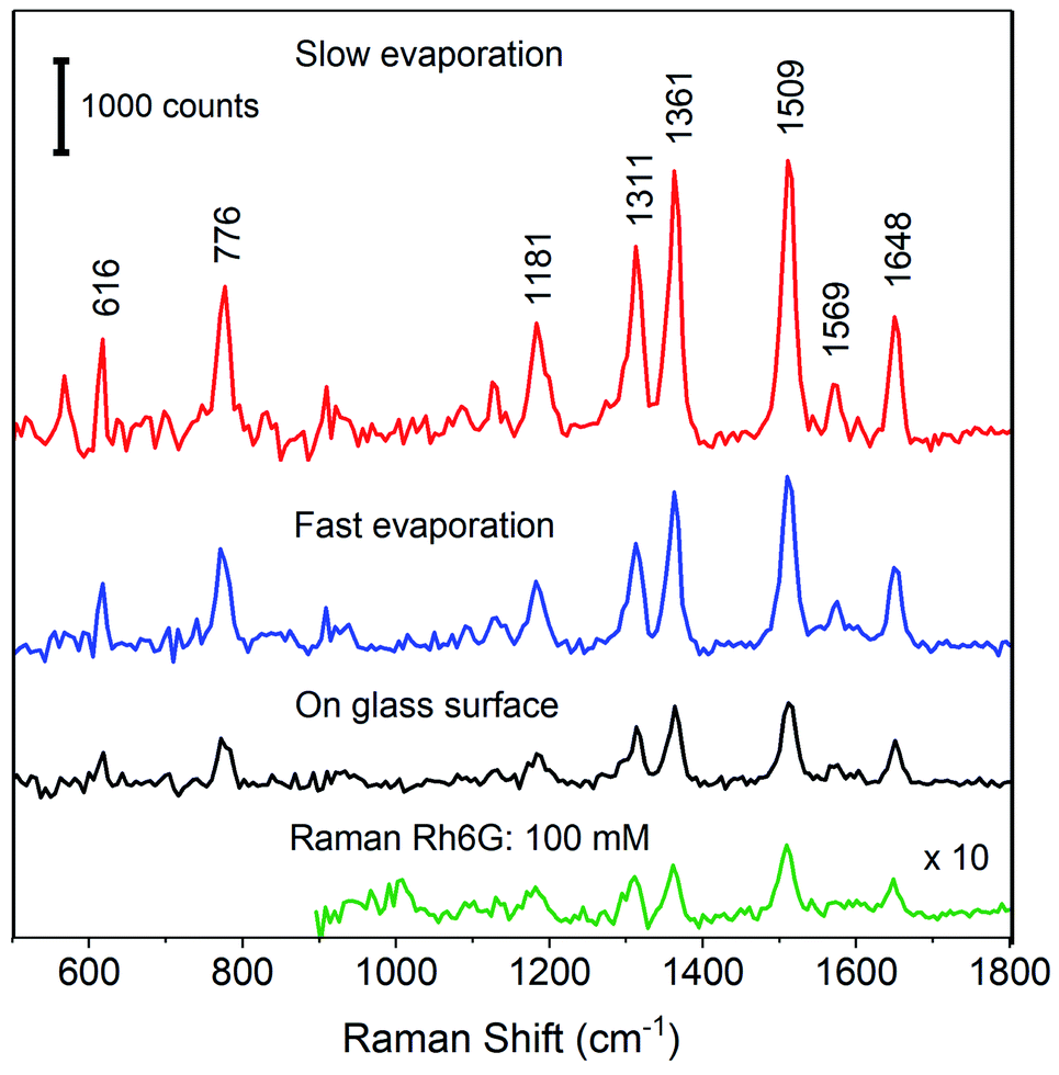 | ||
| Fig. 4 SERS spectra of Rh6G on surfaces prepared using slow evaporation (s_evp), fast evaporation (f_evp) and on hydrophilic cleaned glass surface. The concentration of Rh6G in all cases is 2.5 μM. Bottom panel: Raman spectrum of Rh6G (conc. 100 mM). | ||
In order to investigate the detection sensitivity on PDMS surfaces, SERS spectra were recorded with various concentrations of Rh6G. For experiments, seven sample spots were prepared with Rh6G concentration ranging from 2.5 μM to 2.5 pM. Fig. 5(a) shows the SERS spectra of Rh6G with concentrations ranging from 2.5 μM to 25 pM on f_evp substrate. Fig. 5(b) shows the SERS spectra for the Rh6G from 2.5 μM to 2.5 pM from the spot obtained on the s_evp substrate. It can be clearly seen from Fig. 5(b) that SERS signals were observed from the enriched regions in the drop-casted sample spots and, even with 2.5 pM concentration, the characteristic Raman bands of Rh6G were clearly observed. Observation of SERS signal from each spot confirms the usability and reproducibility of the sample preparation method using slow evaporation. As it is mentioned above, for comparison of SERS strengths on substrates f_evp and s_evp, single point measurement was performed with maximization of the SERS signal. As it can be seen, the lower concentration with clearly observable Raman bands in the case of f_evp substrate was ∼250 pM. For 25 pM concentration, a very small band appears at ∼1609 cm−1 with no trace of other characteristic bands. The intensity of this band is comparable to noise in the spectrum. Therefore, this spectrum was not considered for further analysis. This observed change indicates towards better enrichment of the substrate surface using a slow evaporation process, compared to that obtained with fast evaporation process. In the bottom panel of Fig. 5(a), the Raman spectrum of Rh6G is shown. The spectrum was obtained from dried drop of concentration 100 mM with acquisition time and onboard averaging of 10 and 3 respectively. The Raman spectrum showed in the figure is expanded 10-fold on intensity scale to make the clear appearance of bands.
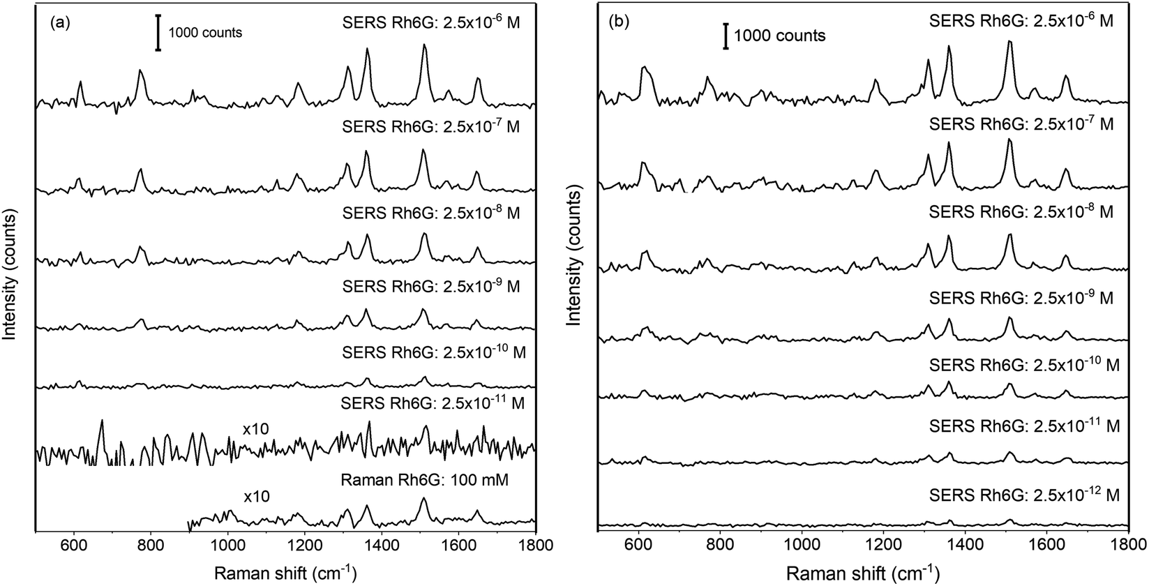 | ||
| Fig. 5 Surface enhanced Raman spectra of rhodamine 6G on hydrophobic (a) f_evp and (b) s_evp substrates. | ||
Fig. 6(a) and (b) shows the variation in the peak intensity of the band observed at 1509 cm−1, on f_evp and s_evp substrates respectively. As it can be seen, in Fig. 6(a), the intensity of the band decreases linearly whereas the decrease is linear only up to 0.25 nM concentration in Fig. 6(b). Below the concentration 0.25 nM in Fig. 6(b), the intensity decrease is slow. The linear fit to the intensity is also shown in the figure. The obtained linear correlation for f_evp substrate was Y = 355 × LogCRh6G + 3637.5 whereas for s_evp substrate, it is Y = 479 × LogCRh6G + 5119. The results show that the enrichment of the sample is better when it is slowly evaporated, and detection of Rh6G molecule up to 2.5 pM can be observed clearly.
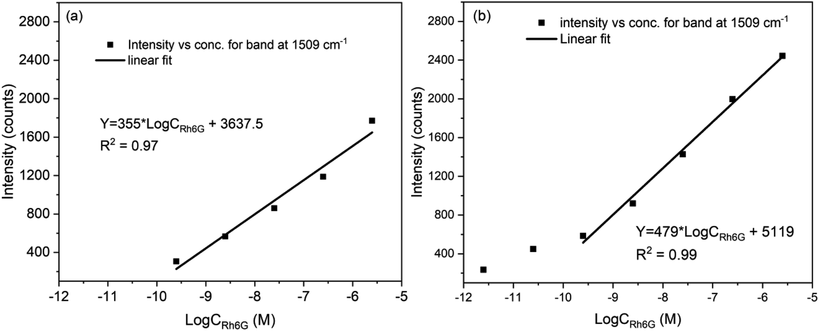 | ||
| Fig. 6 Variation of intensity of band at 1509 cm−1 with concentration of Rh6G on substrate obtained by (a) fast evaporation and (b) slow evaporation. | ||
The enhancement factor was calculated based on the SERS spectra obtained at 2.5 μM concentration using,

4. Conclusions
A soft hydrophobic surface using PDMS was prepared using pre-polymer and curing agent ratio of 50:1. It is shown that the evaporation rate on this PDMS surface controls the dried drop size and the uniformity of analyte distribution in the spot. The slow evaporation of nanoparticle suspension in water under high humid environment minimizes the coffee stain effect and enriches the dried drop compared to the fast evaporation process under low humidity. The substrate prepared with slow evaporation is found to be suitable for the surface enhanced Raman spectroscopy of Rh6G, and concentration as low as 2.5 × 10⁻¹² M was detected. The enhancement factor for the SERS measurement was found to be two time compared to the substrate prepared under low humidity condition. The successful demonstration of the use of simple and easily fabricable hydrophobic surface for the SERS studies is promising for further applications in sensitive and reliable detection of analyte molecules with SERS technique. The sensitivity of the SERS measurement on used soft hydrophobic surface can be further enhanced by using anisotropic Ag nanoparticles with optimized size and shape. This will paves the way for the sensitive detection of analyte molecules other than Rh6G depending on their SERS cross-section.
Conflicts of interest
There are no conflicts to declare.Acknowledgements
Financial support from Department of Science and Technology (DST) India under the project Grant No. IDP/BDTD/11/2019 is gratefully acknowledged.References
- C. Zong, M. Xu, L.-J. Xu, T. Wei, X. Ma, X.-S. Zheng, R. Hu and B. Ren, Chem. Rev., 2018, 118, 4946–4980 CrossRef CAS PubMed.
- H. Chen, A. Das, L. Bi, N. Choi, J.-I. Moon, Y. Wu, S. Park and J. Choo, Nanoscale, 2020, 12, 21560–21570 RSC.
- D. Song, R. Yang, F. Long and A. Zhu, J. Environ. Sci., 2019, 80, 14–34 CrossRef PubMed.
- H. Wei, S. M. Hossein Abtahi and P. J. Vikesland, Environ. Sci.: Nano, 2015, 2, 120–135 RSC.
- R. Pilot, J. Raman Spectrosc., 2018, 49, 954–981 CrossRef CAS.
- S. Dick, M. P. Konrad, W. W. Y. Lee, H. McCabe, J. N. McCracken, T. M. D. Rahman, A. Stewart, Y. Xu and S. E. J. Bell, Adv. Mater., 2016, 28, 5705–5711 CrossRef CAS PubMed.
- J. Wu, L. Zhang, F. Huang, X. Ji, H. Dai and W. Wu, J. Hazard. Mater., 2020, 387, 121714 CrossRef CAS PubMed.
- I. J. Jahn, A. Mühlig and D. Cialla-May, Anal. Bioanal. Chem., 2020, 412, 5999–6007 CrossRef CAS PubMed.
- J. R. Lombardi and R. L. Birke, Acc. Chem. Res., 2009, 42, 734–742 CrossRef CAS PubMed.
- S.-Y. Ding, E.-M. You, Z.-Q. Tian and M. Moskovits, Chem. Soc. Rev., 2017, 46, 4042–4076 RSC.
- M. F. Cardinal, E. Vander Ende, R. A. Hackler, M. O. McAnally, P. C. Stair, G. C. Schatz and R. P. Van Duyne, Chem. Soc. Rev., 2017, 46, 3886–3903 RSC.
- G. Demirel, H. Usta, M. Yilmaz, M. Celik, H. A. Alidagi and F. Buyukserin, J. Mater. Chem. C, 2018, 6, 5314–5335 RSC.
- H. K. Lee, Y. H. Lee, C. S. L. Koh, G. C. Phan-Quang, X. Han, C. L. Lay, H. Y. F. Sim, Y.-C. Kao, Q. An and X. Y. Ling, Chem. Soc. Rev., 2019, 48, 731–756 RSC.
- F. Tian, F. Bonnier, A. Casey, A. E. Shanahan and H. J. Byrne, Anal. Methods, 2014, 6, 9116–9123 RSC.
- K. G. Stamplecoskie, J. C. Scaiano, V. S. Tiwari and H. Anis, J. Phys. Chem. C, 2011, 115, 1403–1409 CrossRef CAS.
- Y. Yang, S. Matsubara, L. Xiong, T. Hayakawa and M. Nogami, J. Phys. Chem. C, 2007, 111, 9095–9104 CrossRef CAS.
- J. Langer, D. Jimenez de Aberasturi, J. Aizpurua, R. A. Alvarez-Puebla, B. Auguié, J. J. Baumberg, G. C. Bazan, S. E. J. Bell, A. Boisen, A. G. Brolo, J. Choo, D. Cialla-May, V. Deckert, L. Fabris, K. Faulds, F. J. García de Abajo, R. Goodacre, D. Graham, A. J. Haes, C. L. Haynes, C. Huck, T. Itoh, M. Käll, J. Kneipp, N. A. Kotov, H. Kuang, E. C. Le Ru, H. K. Lee, J.-F. Li, X. Y. Ling, S. A. Maier, T. Mayerhöfer, M. Moskovits, K. Murakoshi, J.-M. Nam, S. Nie, Y. Ozaki, I. Pastoriza-Santos, J. Perez-Juste, J. Popp, A. Pucci, S. Reich, B. Ren, G. C. Schatz, T. Shegai, S. Schlücker, L.-L. Tay, K. G. Thomas, Z.-Q. Tian, R. P. Van Duyne, T. Vo-Dinh, Y. Wang, K. A. Willets, C. Xu, H. Xu, Y. Xu, Y. S. Yamamoto, B. Zhao and L. M. Liz-Marzán, ACS Nano, 2020, 14, 28–117 CrossRef CAS PubMed.
- C. Li, Y. Huang, X. Li, Y. Zhang, Q. Chen, Z. Ye, Z. Alqarni, S. E. J. Bell and Y. Xu, J. Mater. Chem. C, 2021, 9, 11517–11552 RSC.
- H. Liu, L. Yang and J. Liu, TrAC, Trends Anal. Chem., 2016, 80, 364–372 CrossRef CAS.
- X. Pan, J. Dong, Y. Li, X. Sun, C. Yuan and W. Qian, RSC Adv., 2016, 6, 29586–29591 RSC.
- N. Pazos-Perez, C. S. Wagner, J. M. Romo-Herrera, L. M. Liz-Marzán, F. J. GarcíadeAbajo, A. Wittemann, A. Fery and R. A. Alvarez -Puebla, Angew. Chem., Int. Ed., 2012, 51, 12688–12693 CrossRef CAS PubMed.
- F. De Angelis, F. Gentile, F. Mecarini, G. Das, M. Moretti, P. Candeloro, M. L. Coluccio, G. Cojoc, A. Accardo, C. Liberale, R. P. Zaccaria, G. Perozziello, L. Tirinato, A. Toma, G. Cuda, R. Cingolani and E. Di Fabrizio, Nat. Photonics, 2011, 5, 682–687 CrossRef CAS.
- Y. Gao, T. You, N. Yang, C. Zhang and P. Yin, Adv. Mater. Interfaces, 2019, 6, 1801966 CrossRef.
- H. Li, Q. Yang, J. Hou, Y. Li, M. Li and Y. Song, Adv. Funct. Mater., 2018, 28, 1800448 CrossRef.
- B.-B. Xu, Y.-L. Zhang, W.-Y. Zhang, X.-Q. Liu, J.-N. Wang, X.-L. Zhang, D.-D. Zhang, H.-B. Jiang, R. Zhang and H.-B. Sun, Adv. Opt. Mater., 2013, 1, 56–60 CrossRef.
- P. Kumar, R. Khosla, M. Soni, D. Deva and S. K. Sharma, Sens. Actuators, B, 2017, 246, 477–486 CrossRef CAS.
- G. C. Shi, M. L. Wang, Y. Y. Zhu, L. Shen, W. L. Ma, Y. H. Wang and R. F. Li, Sci. Rep., 2018, 8, 6916 CrossRef PubMed.
- Y. Li, C. Diddens, T. Segers, H. Wijshoff, M. Versluis and D. Lohse, Proc. Natl. Acad. Sci. U. S. A., 2020, 117, 16756 CrossRef CAS PubMed.
- A. Gao, J. Liu, L. Ye, C. Schönecker, M. Kappl, H.-J. Butt and W. Steffen, Langmuir, 2019, 35, 14042–14048 CrossRef CAS PubMed.
- M. Majumder, C. S. Rendall, J. A. Eukel, J. Y. L. Wang, N. Behabtu, C. L. Pint, T.-Y. Liu, A. W. Orbaek, F. Mirri, J. Nam, A. R. Barron, R. H. Hauge, H. K. Schmidt and M. Pasquali, J. Phys. Chem. B, 2012, 116, 6536–6542 CrossRef CAS PubMed.
- C. Liu, E. Bonaccurso and H.-J. Butt, Phys. Chem. Chem. Phys., 2008, 10, 7150–7157 RSC.
- Y. Wang, F. Liu, Y. Yang and L.-P. Xu, Mater. Chem. Front., 2021, 5, 5639–5652 RSC.
- J. Gerber, T. Lendenmann, H. Eghlidi, T. M. Schutzius and D. Poulikakos, Nat. Commun., 2019, 10, 4776 CrossRef PubMed.
- S. Agnihotri, S. Mukherji and S. Mukherji, RSC Adv., 2014, 4, 3974–3983 RSC.
- H. Hegde, C. Santhosh and R. K. Sinha, Mater. Res. Express, 2019, 6, 105075 CrossRef CAS.
- R. K. Sinha, Laser Phys., 2019, 30, 026202 CrossRef.
- C. A. Schneider, W. S. Rasband and K. W. Eliceiri, Nat. Methods, 2012, 9, 671–675 CrossRef CAS PubMed.
- A. F. Stalder, T. Melchior, M. Müller, D. Sage, T. Blu and M. Unser, Colloids Surf., A, 2010, 364, 72–81 CrossRef CAS.
- R. K. Sinha, Instrum. Exp. Tech., 2021, 64, 840–847 CrossRef CAS.
- R. K. Sinha and P. Biswas, J. Mol. Struct., 2020, 1222, 128946 CrossRef CAS.
- R. Pilot and M. Massari, Chem. Phys., 2021, 2, 100014 Search PubMed.
- W. E. Smith and C. Rodger, in Encyclopedia of Spectroscopy and Spectrometry, ed. J. C. Lindon, Academic Press, Oxford, 2nd edn, 1999, pp. 2822–2827, DOI:10.1016/B978-0-12-374413-5.00304-3.
- S. Kruszewski and M. Cyrankiewicz, Acta Phys. Pol., A, 2013, 123, 965–969 CrossRef CAS.
- P. Hildebrandt and M. Stockburger, J. Phys. Chem., 1984, 88, 5935–5944 CrossRef CAS.
- L. Jensen and G. C. Schatz, J. Phys. Chem. A, 2006, 110, 5973–5977 CrossRef CAS PubMed.
| This journal is © The Royal Society of Chemistry 2022 |