 Open Access Article
Design of an efficient, tunable and scalable freestanding flexible membrane for filter application†
Sumit Kumar Pandey and
Anchal Srivastava *
*
Department of Physics, Institute of Science, Banaras Hindu University, Varanasi, 221005, India. E-mail: anchal@bhu.ac.in; anchalbhu@gmail.com; Tel: +91-9453203122
First published on 10th January 2022
Abstract
To address the global challenge of water pollution, membrane-based technologies are being used as a dignified separation technology. However, designing low-cost, reusable, freestanding and flexible membranes for wastewater treatment with tunable pore size, good mechanical strength, and high separation efficiency is still a major challenge. Herein, we report the development of a scalable, reusable, freestanding, flexible and functionalized multiwalled carbon nanotube (FMWCNT) membrane filter with tunable pore size for wastewater treatment, which has attractive attributes such as high separation efficiency (>99% for organic dyes and ∼80% for salts), permeance (∼225 L h−1 m−2 bar−1), tensile strength (∼6 MPa), and reusability of both the membrane as well as contaminants separately. This FMWCNTs membrane filter has been developed by a simple vacuum-assisted filtration technique followed by the synthesis of MWCNTs using a cost-effective spray pyrolysis assisted chemical vapor deposition (CVD) technique and chemical functionalization. This study deals with understanding the rejection, retrieval, and reusability of both the membranes as well as waterborne contaminants separately. The developed membrane filter has potential utility in many applications such as wastewater treatment, food industry, and life sciences due to its robust mechanical and separation performance characteristics.
1. Introduction
Clean water is of utmost importance for every living organism, but due to the rapidly increasing population and industrialization, there is a continuous shortage of clean, safe, and potable water. Moreover, more than 70% of the earth's land is covered by water, but only 2.5% of fresh water is available for use in our daily life.1 According to a recent study by WHO, globally, at least 2 billion people use contaminated water that infects and transmits life-threatening diseases like diarrhea, cholera, dysentery, typhoid, and polio, which causes around 485![[thin space (1/6-em)]](https://www.rsc.org/images/entities/char_2009.gif) 000 deaths every year. Additionally, by 2025, half of the world's population will start living in water-stressed areas.2 The main source of water contamination is wastewater run-off by different industries that contains various waterborne pollutants, such as metal ions, salts, dyes, and bacteria, which must be treated or removed before being discharged into the environment.3,4 Organic pollutants (mostly dyes), which represent an important group of water pollutants, are used in various fields such as plastics, textiles, leather, rubber, food, pharmaceutical, paper, and cosmetics industries, with highly toxic constituents and severe environmental impact.5 Moreover, around 10–15% of commercial dyes produced from these industries are discharged into the environment, rivers, and drains every year without any treatment, most of which are toxic and carcinogenic.6 Thus, the increase in water contamination by these organic pollutants needs to be addressed urgently, as this will lead to severe impacts on the environment, human health and water scarcity. In this respect, various techniques such as coagulation, chemical precipitation, adsorption, oxidation, membrane filtration, photocatalytic degradation, electrochemical treatment, reverse osmosis, liquid–liquid extraction, ion exchange, and gravity have already been considered to remove these pollutants from industrial wastewater.7 Of these, membrane filtration has been considered the most effective technique as it provides good safety, low energy consumption, short operating time, and environmental compatibility, as compared to other purification processes.8,9 In recent years, membrane technology for wastewater treatment has also progressively been advanced to address the global challenges of increasing water pollution by these organic contaminants. In this regard, a wide range of new nanostructured materials such as carbon nanomaterials (e.g., carbon nanotubes,10 graphene,11 etc.), biomaterials (e.g., cellulose acetate,12 proteins,13 silk nanofibrils,14 etc.), inorganic nanomaterials (e.g., graphene oxide,15 molybdenum disulfide,16 tungsten disulfide,17 etc.), and polymers18–20 along with novel fabrication techniques like chemical vapor deposition,21,22 track etching,23,24 template synthesis,25,26 and layer-by-layer assembly27 have been widely considered to design membrane filters. However, these materials and methods hold many disadvantages such as complex manufacturing processes, brittleness, high cost, risk of swelling when exposed to water, low mechanical resilience, less durability, and difficulty in efficient and accurate production of multilayer porous structures to achieve optimized separation performance.28–32 Therefore, designing cost-effective, reusable, freestanding, flexible water purification membranes with good mechanical strength and high filtration efficiency in large-scale for rapid removal of noxious contaminants from wastewater and retrieving both membranes as well as contaminants separately is still a major challenge.
000 deaths every year. Additionally, by 2025, half of the world's population will start living in water-stressed areas.2 The main source of water contamination is wastewater run-off by different industries that contains various waterborne pollutants, such as metal ions, salts, dyes, and bacteria, which must be treated or removed before being discharged into the environment.3,4 Organic pollutants (mostly dyes), which represent an important group of water pollutants, are used in various fields such as plastics, textiles, leather, rubber, food, pharmaceutical, paper, and cosmetics industries, with highly toxic constituents and severe environmental impact.5 Moreover, around 10–15% of commercial dyes produced from these industries are discharged into the environment, rivers, and drains every year without any treatment, most of which are toxic and carcinogenic.6 Thus, the increase in water contamination by these organic pollutants needs to be addressed urgently, as this will lead to severe impacts on the environment, human health and water scarcity. In this respect, various techniques such as coagulation, chemical precipitation, adsorption, oxidation, membrane filtration, photocatalytic degradation, electrochemical treatment, reverse osmosis, liquid–liquid extraction, ion exchange, and gravity have already been considered to remove these pollutants from industrial wastewater.7 Of these, membrane filtration has been considered the most effective technique as it provides good safety, low energy consumption, short operating time, and environmental compatibility, as compared to other purification processes.8,9 In recent years, membrane technology for wastewater treatment has also progressively been advanced to address the global challenges of increasing water pollution by these organic contaminants. In this regard, a wide range of new nanostructured materials such as carbon nanomaterials (e.g., carbon nanotubes,10 graphene,11 etc.), biomaterials (e.g., cellulose acetate,12 proteins,13 silk nanofibrils,14 etc.), inorganic nanomaterials (e.g., graphene oxide,15 molybdenum disulfide,16 tungsten disulfide,17 etc.), and polymers18–20 along with novel fabrication techniques like chemical vapor deposition,21,22 track etching,23,24 template synthesis,25,26 and layer-by-layer assembly27 have been widely considered to design membrane filters. However, these materials and methods hold many disadvantages such as complex manufacturing processes, brittleness, high cost, risk of swelling when exposed to water, low mechanical resilience, less durability, and difficulty in efficient and accurate production of multilayer porous structures to achieve optimized separation performance.28–32 Therefore, designing cost-effective, reusable, freestanding, flexible water purification membranes with good mechanical strength and high filtration efficiency in large-scale for rapid removal of noxious contaminants from wastewater and retrieving both membranes as well as contaminants separately is still a major challenge.
The discovery of carbon nanotubes (CNTs) sheds light on achieving the ideal membrane filters because CNTs not only have a high aspect ratio and large surface area but also ceramic-like stability, polymer-like flexibility, biomaterials-like unique open tubular nanochannels, and possible processabilities.33 Moreover, several studies have also described that water permeation through CNTs is very fast.34–39 For example, Yang et al.30 have reported the fabrication of carbon nanomembranes using terphenylthiol monolayers in which water permeance has been found to be around ∼1.1 × 10⁻⁴ mol m−2 s−1 Pa−1. In another report, Yang et al.40 have reported the removal of various organic dyes and salts such as methylene blue, rhodamine B, KCl, NaCl, etc., using a hybrid membrane of graphene nanomesh and carbon nanotube with a maximum permeance of ∼37.2 L m−2 h−1 bar−1. In another report, Vecitis et al.41 have reported the adsorptive removal and electrochemical oxidation of aqueous dyes and anions by electrochemically active carbon nanotube filter using electrochemical filtration technique. In another report, Byeongho Lee et al.42 have reported the development of a millimetre thick vertically aligned carbon nanotube wall membrane for water treatment having very high water permeability ∼30, 000 L m−2 h−1 bar−1. In all the above reports, the authors have attempted relatively complex and tedious processes that are not even cost-effective. Moreover, the practical applications of such CNTs based membrane filters are still challenging because the methods of synthesis and designing them often face a variety of problems, such as, sophisticated equipment, time consuming and complex procedures for obtaining high density vertically aligned CNTs, relatively high cost, and difficulties in large-scale production.32 Furthermore, most of the research articles reported on membranes have focused on membrane processing, surface modification, filtration efficiency, and water permeability. However, experimental investigations of mechanical behaviour under complex loading modes for such membranes are generally not given much importance and are rarely reported. Therefore, to overcome the above deficiencies, we have used FMWCNTs to design a membrane filter with tunable pore size, which offers better mechanical robustness, more flexibility, permeability, and chemically active sites that assist in designing a more efficient, scalable, and economical membrane filter for wastewater treatment.43,44 Furthermore, we can easily reuse both membrane and contaminants separately by a simple ultrasonication technique.
Herein, we report the development of a scalable, reusable, freestanding, flexible, and binder-free FMWCNTs membrane filter with tunable pore size for wastewater treatment, which has attractive attributes of high separation efficiency (>99% for organic dyes and ∼80% for salts), permeance ∼225 L h−1 m−2 bar−1 (around 10 times greater than most commercial membrane filters), tensile strength ∼6 MPa, and reusability of both membranes as well as contaminants separately. This FMWCNTs membrane filter has been developed by a simple vacuum-assisted filtration technique followed by the synthesis of MWCNTs using cost-effective spray pyrolysis assisted CVD technique and chemical functionalization. In this study, we have also provided a detailed understanding of the rejection, recovery, and reusability behavior of both membranes and waterborne contaminants.
2. Experimental
2.1. Materials
Ferrocene (C10H10Fe) has been purchased from Alfa Aesar, India. Toluene (C7H8), acetone (C3H6O), nitric acid (HNO3), sulfuric acid (H2SO4), rhodamine B (C28H31ClN2O3), methylene blue (C16H18ClN3S), methyl violet (C24H28N3Cl), sodium chloride (NaCl), magnesium sulfate (MgSO4), heptahydrate (MgSO4·7H2O), sodium sulfate (Na2SO4), and magnesium chloride hexahydrate (MgCl2·6H2O) have been procured from Molychem, India. All the chemicals were of analytical grade and used as received.2.2. Synthesis of MWNCTs
MWCNTs were synthesized using the spray pyrolysis assisted CVD technique, adopting the procedure described in our earlier reported work.45,46 Briefly, the homogeneous solution of ferrocene and toluene was sprayed with the aid of argon gas inside a quartz tube furnace maintained at 900 °C, as shown in Fig. S1.† After the completion of spray pyrolysis, the quartz tubing furnace was cooled to ambient temperature under an argon gas flow. Subsequently, a dense black film made of MWCNTs inside the quartz tube was scraped off and collected for further investigations.2.3. Functionalization of MWCNTs
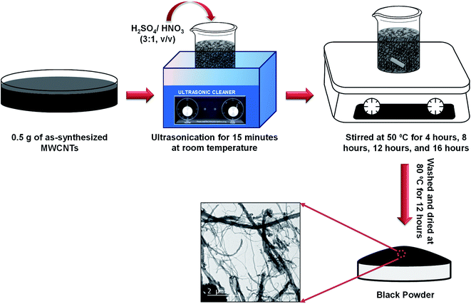
Due to the high chemical inactivity and hydrophobic character, chemistry on CNTs came later into the play. Among the various functionalization techniques, acidic oxidation methods have been extensively studied as an effective technique to make the surfaces of CNTs pure, hydrophilic, and chemically functional. Thus, to functionalize the as-synthesized MWCNTs, 0.5 g of as-synthesized MWCNTs was dispersed in a solution mixture of H2SO4/HNO3 (3![[thin space (1/6-em)]](https://www.rsc.org/images/entities/char_2009.gif) :
:![[thin space (1/6-em)]](https://www.rsc.org/images/entities/char_2009.gif) 1, v/v). The mixture was sonicated in an ultrasonic water bath maintained at room temperature and then stirred at 50 °C for 4 h, 8 h, 12 h, and 16 h, to know the effect of stirring. Thereafter, the mixtures were filtered and thoroughly washed by DI water several times up to pH 7 and dried at 80 °C overnight prior to further investigations. The schematic of the overall process is shown in Fig. 1.
1, v/v). The mixture was sonicated in an ultrasonic water bath maintained at room temperature and then stirred at 50 °C for 4 h, 8 h, 12 h, and 16 h, to know the effect of stirring. Thereafter, the mixtures were filtered and thoroughly washed by DI water several times up to pH 7 and dried at 80 °C overnight prior to further investigations. The schematic of the overall process is shown in Fig. 1.
2.4. Preparation of FMWCNTs membrane
FMWCNTs membrane was prepared by a simple vacuum-assisted filtration technique, adopting a similar procedure described in our earlier reported work.47 In brief, 0.5 g of FMWCNTs was well dispersed in 100 mL of acetone using ultra-sonicator and high-speed homogenizer. After that, the well-dispersed suspension of FMWCNTs was filtered by a vacuum filtration unit, and consequently, a uniform black film was deposited over the Whatman filter paper. After that, the binder-free freestanding flexible film made up of FMWCNTs was dried and peeled off from the Whatman filter paper prior to use as a membrane filter for wastewater treatment, as shown in Fig. 2.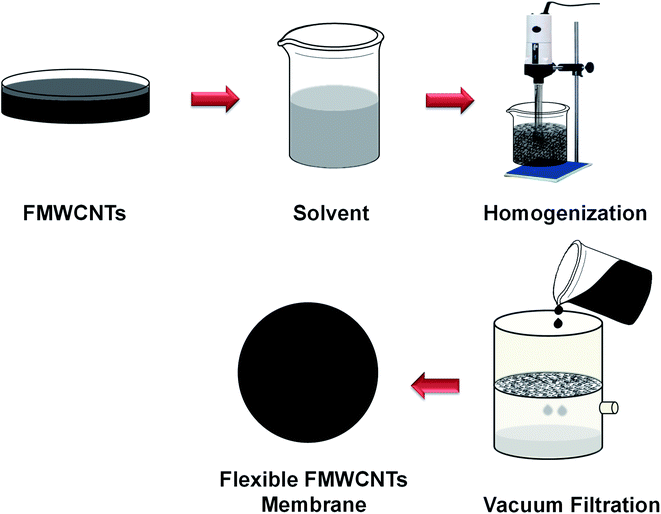 | ||
| Fig. 2 Schematic diagram of the preparation of the reusable, freestanding, and flexible FMWCNTs membrane. | ||
Herein, we found that it was very difficult to design freestanding and flexible membranes for samples stirred for 8 h or more, which is caused by the increase in ID/IG value as well as the decrease in the aspect ratio of as synthesized MWCNTs after chemical functionalization, as shown in Fig. S2.† The MWCNTs stirred for up to 4 h possess a good aspect ratio with chemically active sites, which assist in designing uniform, continuous, lightweight, freestanding, flexible membranes having the smooth passage of water through it. Moreover, the prepared self-supporting flexible membrane can also be scaled to the desired dimensions (length × width) simply by selecting the dimensions of the vacuum filtration unit and the concentration of FMWCNTs. Thus, the as-prepared membrane can be freely cut into the desired shape and size prior to use.
2.5. Filtration performance measurement
The filtration experiments were performed through a syringe filtration setup (Tarsons syringe filter) with constant pressure at 1 bar, adopting similar procedure as described in the previously reported works.8,48 The FMWCNTS membrane was inserted and sealed in a syringe holder with two O-rings at the top and bottom to protect against leakage. Moreover, for the flux assessments, we followed the method used for other membranes.8,14,49 Typically, by measuring the volume of water or model compound solution passing through the as-prepared membrane under constant pressure as a function of time, the flux J (liter hour−1 m−2 bar−1) was calculated using the following equation:
 | (1) |
 | (2) |
3. Result and discussion
X-ray diffractometer (PANalytical, UK), scanning electron microscope (SEM) (ZEISS, Germany), atomic force microscope (AFM) (Park XE7, South Korea), and transmission electron microscope (TEM) (TECNAI 20 G2) operating at accelerating voltage of 200 kV were used for the structural and morphological characterization of the synthesized samples and designed membrane. Raman microscope (WITec alpha300 R|A|S, Germany), Fourier transform infrared (FTIR) spectrometer (Frontier, PerkinElmer, USA), and UV-vis spectrometer (Shimadzu, Japan) were used for the spectroscopic characterizations of the samples. Gemini VII 2390 surface area analyzer (Micromeritics, US), 851e thermal analysis (Mettler Toledo), and Instron universal testing machine were used for the determination of specific surface area, thermogravimetric analysis (TGA), and the tensile strength of the designed membranes, respectively.3.1. Characterization of FMWCNTs
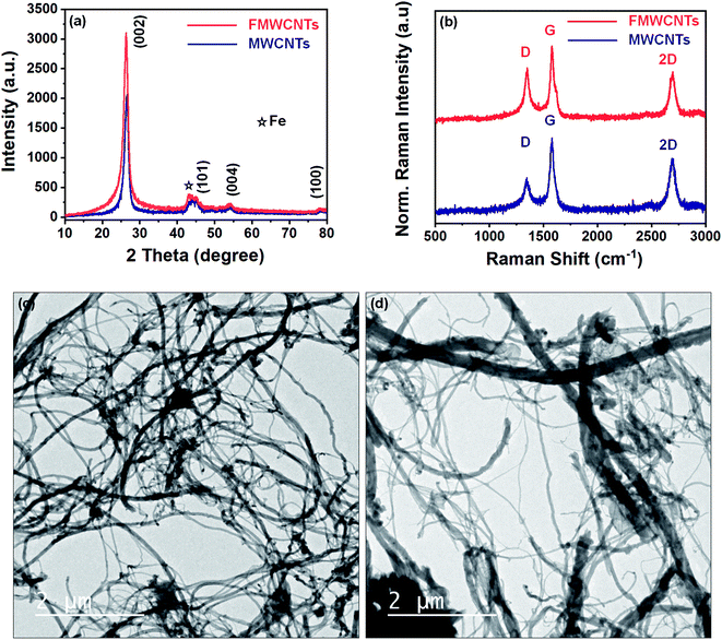
The crystal structure of as synthesized MWCNTs and FMWCNTs has been investigated by powder X-ray diffraction method using Cu-Kα radiation. Fig. 3a shows the typical XRD patterns of as synthesized MWCNTs and FMWCNTs. The pattern exhibits an intense diffraction peak around 2θ = 26° and low intense diffraction peaks around 44°, 53°, and 78° for both MWCNTs and FMWCNTs, which correspond to the planes (002), (101), (004), and (100) respectively, which have been successfully indexed via JCPDS card no. 751621. Furthermore, a low intense diffraction peak around 2θ = 43° corresponds to Fe (JCPDS card no. 654150) used as a catalyst during synthesis. Interestingly, it has been observed that the intensity of the (002) diffraction plane in FMWCNTs is higher than the as synthesized MWCNTs due to the different functional groups introduced over its surfaces after acid treatment. This leads to the conclusion that FMWCNTs have preserved the pure and well graphitized hexagonal structure of MWCNTs even after the functionalization process.Raman spectroscopy has been performed to evaluate the purity, defects, tube alignment, and the presence of nanotubes relative to other carbon allotropes. Fig. 3b depicts the recorded Raman spectra of as synthesized MWCNTs and FMWCNTs using 532 nm laser excitation. As shown in the figure, the recorded spectra have characteristic peaks around 1348 cm−1, 1577 cm−1, and 2696 cm−1 known as D-band, G-band, and 2D-band, which are due to the scattering from local defects or disorders, tangential vibration of C-atoms, and the two-phonon second-order scattering process present in the synthesized MWCNTs, respectively. The intensity ratio of the D band to G band (ID/IG) has been used for the evaluation of the graphitic structure of CNTs. Relatively higher ID/IG = 0.86 values of FMWCNTs than ID/IG = 0.48 values of MWCNTs suggest the presence of more defect sites in the graphitic lattice of MWCNTs after acid treatment. This also confirms the high quality and graphitic nature of synthesized samples.
Transmission electron microscopy was used to investigate possible MWCNTs fragmentation that occurred during treatment. Fig. 3c and d shows typical TEM images of the as-synthesized nanotubes as well as those treated with a solution mixture of H2SO4/HNO3, respectively. As shown in Fig. 3c, the as synthesized MWCNTs have smooth surface structures and high aspect ratio nanotubes. In comparison, MWCNTs, after acid treatment, have rough surface structures and shorter length nanotubes, as shown in Fig. 3d. The slight roughness on the surface of FMWCNTs might be due to the defect sites formed due to the attachment of chemical functional groups on the surface after acid treatment and shorter length due to ultrasonication.
The surface roughness is an important factor that strongly influences the filtration behavior of the designed membrane in terms of surface adhesion, permeation properties, etc. Since the designed membrane comprises chemically functionalized MWCNTs, we have performed AFM measurements in order to examine the surface roughness of carbon nanotubes before and after acid treatment, as shown in Fig. 4. From Fig. 4a and b, it can be clearly observed that the average roughness in nanotubes before and after acid treatment is ∼78 nm and ∼112 nm, respectively. This average roughness has been measured across the three different regions for each of the recoded AFM images, as highlighted by the square boxes in the figures. This suggests that there are not many changes in the surface roughness of carbon nanotubes after acid treatment, which reflects a good characteristic of the membrane for filter applications.
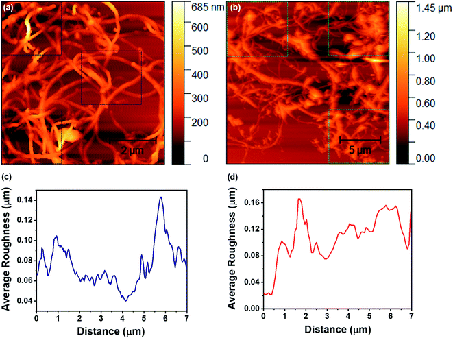 | ||
| Fig. 4 (a) and (b) depict the AFM topography of the MWCNTs and FMWCNTs, respectively. (c) and (d) represent the average roughness on the surface of the MWCNTs and FMWCNTs, respectively. | ||
3.2. Characterization of FMWCNTs membrane
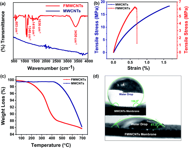
To investigate the functionalization validity and identify the functional groups present over the designed membrane, the FTIR spectra of MWCNTs and functionalized MWCNTs membranes have been recorded, and their corresponding spectra have been shown in Fig. 5a. As shown in the figure, the FTIR spectra recorded for MWCNTs membrane have not exhibited any absorption band. However, some absorption bands around 603 cm−1, 1348 cm−1, 1418 cm−1, 1636 cm−1, and 3430 cm−1 have been observed in the FTIR spectrum of functionalized MWCNTs membrane, which correspond to C–H bending, C–O stretching, C–C stretching, stretching vibrations of carbonyl groups (C![[double bond, length as m-dash]](https://www.rsc.org/images/entities/char_e001.gif) O) present in carboxylic acids (RCOOH), and O–H stretching, respectively.50,51 This is in good agreement with the results shown in XRD and Raman characterizations. The high intensity of the (002) plane and relatively high ID/IG ratio prove the addition of functional groups over nanotube surfaces, which has also validated the success of the functionalization process. This modification further improves the dispersion or wetting behaviour of MWCNTs.
O) present in carboxylic acids (RCOOH), and O–H stretching, respectively.50,51 This is in good agreement with the results shown in XRD and Raman characterizations. The high intensity of the (002) plane and relatively high ID/IG ratio prove the addition of functional groups over nanotube surfaces, which has also validated the success of the functionalization process. This modification further improves the dispersion or wetting behaviour of MWCNTs.
In addition to high flux and high contaminant rejection, water treatment membranes are also required to have good mechanical stability and durability. Thus, it is very important to test the membranes for their mechanical properties under conditions similar to the actual loading conditions, as most of the membranes are subjected to stress and the accompanying deformation during processing and use. Therefore, to examine the potential suitability, the mechanical properties of the designed FMWCNTs membrane have been characterized by stress–strain tests, as shown in Fig. 5b. Typically, the measured tensile strength of designed MWCNTs and FMWCNTs membranes has been found to be around ∼18.3 MPa and ∼6 MPa, respectively, indicating that the designed FMWCNTs membrane still retains the good mechanical strength for the purpose of wastewater treatment.
Further, to understand the thermal stability of the designed MWCNTs and FMWCNTs membranes, the TGA measurements were performed. Fig. 5c shows the typical comparative TGA curves of the designed membranes, clearly showing that the designed MWCNTs and FMWCNTs membranes possess good thermal stability up to ∼450 °C and ∼250 °C, respectively, which is quite good for wastewater treatment. In the typical TGA curve obtained for FMWCNTs, the weight loss starting around ∼250 °C is mainly due to the existence of oxygen containing functional groups and the little moisture present over the designed FMWCNTs membrane. Moreover, weight loss starting around ∼450 °C is due to the decomposition of nanotubes and a small amount of amorphous carbon. However, due to the absence of functional groups and moisture, the weight loss in MWCNTs membranes begins at ∼450 °C.
The contact angle is an extremely important and widely used analysis for the characterization of the hydrophobic/hydrophilic behaviour of membranes as it plays an important role in separation technology. Fig. 5d clearly explains this behavior of the designed membrane. As shown in the inset of Fig. 5d, the water droplets over the surface of pristine MWCNTs membrane exhibit a contact angle of ∼156.9°, indicating the super hydrophobic behavior. Whereas the water droplets over the surface of the FMWCNTs membrane exhibit a contact angle of ∼41.3°, indicating the hydrophilic behavior of the designed membrane after acid treatment. This hydrophilic behavior of the designed FMWCNTs membrane assists the smooth and rapid passage of water through the membrane.
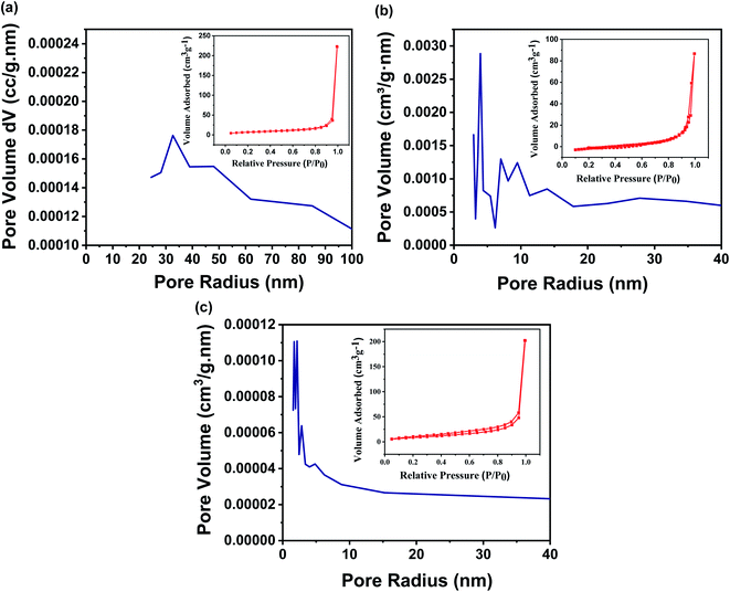
The earlier reports show that the characteristics like surface area, pore structures, pore size, and pore size distribution of a membrane are the backbone of the membrane separation technology as they govern the filtration behaviour of the membranes. Although the designed membrane comprises chemically functionalized MWCNTs, which are randomly oriented and entangled to each other, as a result, the pores are crocked rather than being straight. In this regard, BET is a widely explored technique to analyze the surface area and pore size distribution of the designed membrane. Fig. 6a–c shows the N2 adsorption/desorption isotherms of the designed membrane with different concentrations of FMWCNTs in fixed filtration volume. This suggests that the pore size of the designed membrane has been tuned from 1.7 nm to 27.4 nm, simply by varying the concentration of FMWCNTs from 0.5 g to 0.3 g, respectively (summarized in Table S1†), well supported by the earlier reported work on a membrane with tunable pore size.14
3.3. Filtration performance of the designed membrane
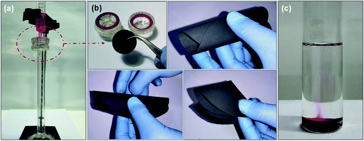
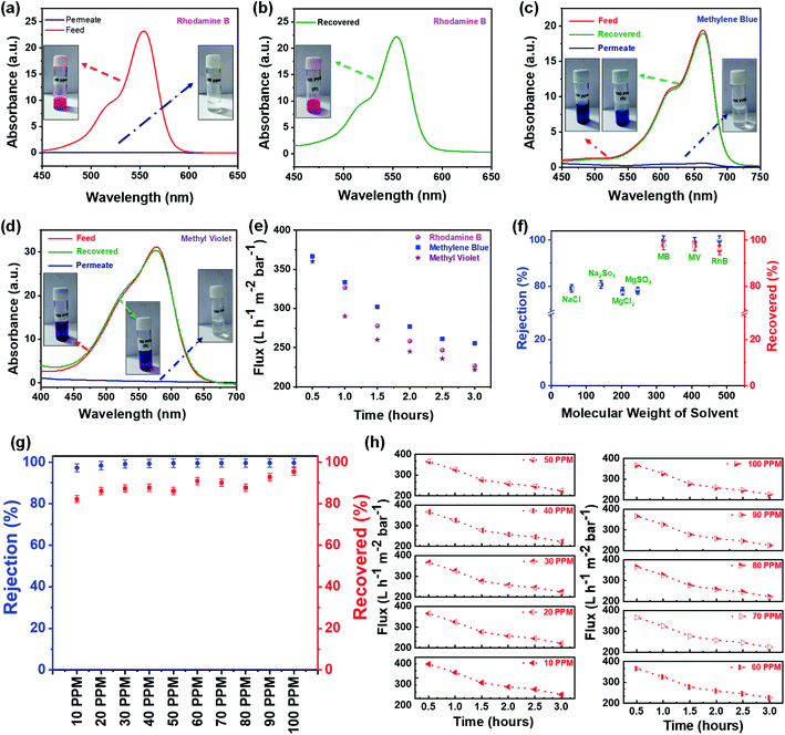
Further, the filtration performance of the designed membrane has been examined for various waterborne contaminants, such as rhodamine B, methylene blue, methyl violet, sodium chloride, magnesium sulfate, sodium sulfate, magnesium chloride, etc. using a dead-end syringe filtration setup, followed by UV-vis analysis of feed and permeate solutions. Fig. 7a–c shows the optical image of nano-filtration setup, flexibility of the designed membrane used for filtration, and the extrusion of waterborne contaminant from the designed membrane indicating the reusability of both designed membrane and contaminant, respectively.These visuals have been further confirmed via recording the UV-vis absorption spectra of feed and permeate solutions. As shown in Fig. 8a, the feed solution of rhodamine B (10 mg L−1) has an intense absorption peak around 555 nm, while this absorption peak has almost disappeared in the permeate solution after filtering with the designed membrane, indicating that the rejection efficiency is >99%. Subsequently, the contaminant enmeshed into the membrane and membrane itself has been re-differentiated by a simple ultrasonication technique. In brief, the membrane after filtration has been re-dispersed in acetone (the same solvent used for membrane preparation) by ultrasonication. Thereafter, the well dispersed suspension of the used membrane has been filtered using a vacuum-assisted filtration unit to re-differentiate the contaminants and membrane, as shown in Fig. S3.† Fig. 8b shows the UV-vis absorption spectra of the recovered contaminant (rhodamine B), indicating that more than 95% of enmeshed rhodamine B has been successfully detracted from the membrane. In addition, we have also studied the influence of other waterborne contaminants such as methylene blue, methyl violet, and various salts like sodium chloride, magnesium sulfate, sodium sulfate, magnesium chloride, etc., on the separation performance of the designed membrane. Fig. 8c–e shows the separation performance of the designed membrane for these contaminants, indicating that the designed membrane holds high separation efficiency (>99% for organic dyes and ∼80% for salts as shown in Fig. S4†), having a permeance of ∼225 L h−1 m−2 bar−1 (around 10 times greater than most commercial membrane filters) in all cases. Furthermore, the membranes as well as contaminants have also been re-differentiated in some cases, as summarized in Fig. 8f. Mostly, it has been observed that a low concentration of contaminants usually limits the separation performance of membranes. Therefore, we have investigated the separation performance of the designed membrane even at low concentrations (1 mg L−1 to 10 mg L−1) of contaminants (rhodamine B has been chosen as a model in view of their acute noxious risk, stability, and complex chemical structure). As a result, we did not observe any change in its performance. In all cases, both visual and absorbance of the permeate solution become transparent and lighter with almost constant flux, as shown in Fig. 8g and h. The UV-vis spectra shown in Fig. S5† also confirm these visual results, adjudicating no absorbance corresponding to these contaminants. Furthermore, the calculations showed that the rejection exceeds >99% in all cases, as well as the extrusion of contaminants from the designed membrane is more than 95%. Also, as shown in Fig. S6 and S7† the permeance and normalized permeance have been made with reference to its filtration efficiency, indicating that the permeance is almost the same in all cases. This can also be seen clearly in the movies S1 and S2.† This suggests that the designed membrane exhibits a comparable or better balance of flux, separation efficiency, and retrieval performance than the other filtration materials used in the literature.11,15–17,34,40,41,49,52–54 Thus, the membrane designed in this work expands the possibilities for potential utility in wastewater treatment technologies.
3.4. Understanding the filtration and reusability behavior of the designed membrane
It is well known that the membrane characteristics like pore size, pore size distribution, pore structures, pore density, surface area, surface roughness, and surface functionalities are the backbone of the membrane separation technology, as they govern the filtration properties of the membrane filters. Therefore, to understand the origin of high separation performance, re-differentiation, and reusability of both designed membrane and contaminants, we have studied these characteristics in detail. The high separation efficiency of the designed membrane can be very well understood by two main mechanisms: (1) physical sieving by membrane pores and (2) the interactions between the negatively charged surface of membrane and contaminants. Remarkably, it has been found that the typical pore size of the designed membrane is comparable to the molecular dimension of these waterborne contaminants, which raises the prospects of size-based exclusion and separation, i.e., physical sieving of these waterborne contaminants. In addition, the pore size of the designed membrane can also be controlled by choosing the appropriate concentration of FMWCNTs in a fixed filtration volume. Therefore, an additional experiment was performed to probe the dominating separation mechanism for dye molecules by measuring the concentration change in the upper stream, i.e., feed solutions. If the physical sieving i.e., size-based separation, is dominated over the absorption/adsorption process, the concentration of dye molecules in the upper stream would change obviously with increasing permeation volume. As shown in Fig. 9a and b, the concentration of the dye molecule in the upper stream increases gradually as the permeation volume increases with an increase in time. Therefore, the physical sieving by the pores of the designed membrane is believed as the dominating factor for the separation of organic dyes, which is well supported by the earlier reported work.34 However, the interactions of functional groups present over the membrane surface with charged dye molecules also could not be completely ignored, as they aid in enhancing the filtration performance.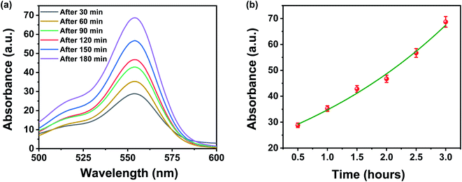 | ||
| Fig. 9 (a and b) UV-vis absorbance changes of upper stream of rhodamine B when the permeation time was 30, 60, 120, 150, and 180 min under a constant pressure of 1 bar. | ||
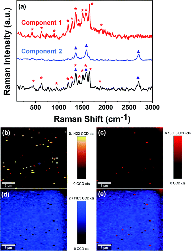
Further, to confirm the physical sieving, we have performed the large-area Raman imaging and true component analysis of the used membrane via Raman spectrophotometer (WITec alpha 300 R|A|S). From Fig. 10a, it can be clearly seen that the large area Raman spectrum of the used membrane consists of two components. The first component possesses sharp peaks around 426 cm−1, 626 cm−1, 896 cm−1, 1197 cm−1, 1286 cm−1, 1357 cm−1, 1435 cm−1, 1511 cm−1, 1575 cm−1, 1651 cm−1, and 1916 cm−1, which well matches with the characteristic peaks of rhodamine B. The second component has peaks around 1357 cm−1, 1590 cm−1, and 2715 cm−1, corresponding to the characteristic peaks of FMWCNTs used to design the membrane. Further, Fig. 10b shows the large-area confocal Raman image of the membrane surface after filtration assessment, revealing the presence of enmeshed fluorescent rhodamine B as bright spots. Fig. 10c–e shows the extracted color-coded Raman image of component 1, i.e., enmeshed contaminant rhodamine B, component 2, i.e., FMWCNTs, and the combined image of components 1 and 2, respectively, showing the presence of rhodamine B in the membrane. In the color-coded combined image of components 1 and 2, it can be clearly seen that the rhodamine B molecules (red and light-red spots) are spread over the membrane, suggesting that the dye molecules are trapped in the membrane pores. This confirms that physical sieving is the dominating factor in separating organic dyes.
Next, the designed membranes not only exhibit excellent filtration efficiency for organic contaminants, but also offer a new and faster way to re-differentiate both membranes as well as organic contaminants separately. Herein, we can easily extract the organic contaminants from the membrane by re-dispersing the used membrane in an organic solvent that was used to design the membrane, as described in Section 2.4. Thereafter, the membrane can be brought back into use for the same purpose. However, organic dyes dissolved in acetone can be further used for dyeing as acetone is highly volatile in nature. The separation of organic dyes from the membrane is merely due to better dispersion of FMWCNTs in such organic solvents and greater solubility coefficient of organic dyes in acetone.55,56 Briefly, the re-dispersion of FMWCNTs membrane in acetone using ultrasonication leads to the rupture of membrane mesh, and as a result, the dye molecules enmeshed into the membrane pores as well as on the surfaces easily dissolve in acetone, which is further separated with the help of vacuum filtration. In this way, we have reclaimed both membrane and contaminants separately.
Despite having moderate retention compared to reverse osmosis, membrane technology is one of the most commonly used techniques for separating the ions from contaminated ionized water, as they have lower pumping and membrane cost than reverse osmosis, which bring forward them as an economically attractive option. In addition to the characteristics discussed above, the separation performance of salts also strongly depends on the charge characteristics of the membrane. Thus, as an exploratory study, we have investigated the separation performance of our designed membrane for four different salts MgSO4, MgCl2, NaCl, and Na2SO4 at a concentration of 1 M at a constant pressure of 1 bar. Remarkably, high rejections of ∼81%, ∼79%, ∼78%, and ∼77% have been observed for Na2SO4, NaCl, MgSO4, and MgCl2, respectively. This rejection can be understood by the Donnan exclusion principle commonly used to explain the separation mechanism for charged membranes. As mentioned above, the designed membrane is negatively charged due to the presence of carboxylic and hydroxyl functional groups over the membrane surface because of chemically functionalized multiwalled carbon nanotubes. In brief, according to the Donnan exclusion theory, at the interphase of the membrane and solution, the Donnan potential set out to separate the co-ions (the ions holding a similar charge as the membrane) from the membrane. Further, in order to maintain the electroneutrality of the solution, the counter ions (the ions holding an opposite charge as to the membrane) were also rejected as well. Consequently, at the interface of solution/membrane, there is local charge separation with a slight excess charge just outside the membrane, compensated by an equally large, but opposite, excess charge located just within the membrane. As a result, with the passage of time, an electrical double layer (EDL) is formed, and the permeance becomes slightly low.57 Thus, it can be seen that the rejection efficiency of the membrane designed in this work is better than or comparable to other reported research works as tabulated in Table 1. This suggests that the designed membrane filter is highly efficient and economical for wastewater treatment.
| Materials | Method adopted to design membrane | Mechanical strength (MPa) | Average pore size (nm) | Permeability (L h−1 m−2 bar−1) | Filtration efficiency (%) | Reusability | Ref. |
|---|---|---|---|---|---|---|---|
| Ultrathin graphene | Vacuum filtration | — | 1–2 | 21.8 | >99 | No | 34 |
| Graphene oxide nanosheets | Layer-by-layer deposition | 0.3 | 10–30 | 276 | 93–95 | No | 15 |
| Functionalized graphene oxide | Pressurized self-assembled technique | 0.25–1.5 | — | 2.8–9.1 | 48.2–91.3 | No | 52 |
| PVP-modified MWCNTs | Phase inversion precipitation method | 1.5 | — | 270 | 48.2–91.3 | No | 53 |
| Graphene–nanomesh/carbon–nanotube hybrid | CVD | 2–4 | 0.55–1.41 | 37.2 | 96.4–98.7 | No | 40 |
| MoS2 | Vacuum filtration | 1.0 | 45 | 245 | 88.1–92.3 | No | 16 |
| WS2 | Vacuum filtration | 0.3–0.4 | 2–4 | 331–747 | 41–99 | No | 17 |
| Metal (Cr)–organic (MeOH) frameworks | Hand-cast on cross-linked PI P84 supports through interfacial polymerization | 0.6 | 3.4 | 1.5–11.1 | 90 | No | 58 |
| FMWCNTs | Vacuum filtration | 6 | 1.7–27.4 | 225 | >99 | Yes | This work |
4. Conclusion
In summary, we report a novel, scalable, reusable, freestanding, flexible, binder free FMWCNTs membrane for the elimination of waterborne contaminants from wastewater, designed via a simple vacuum-assisted filtration technique followed by cost-effective spray pyrolysis assisted CVD synthesis and chemical functionalization, respectively. Subsequently, the designed membrane has been well characterized by various characterization techniques such as FTIR, BET, TGA, and tensile tests, suggesting that the resulting membrane is highly flexible, porous, mechanically robust, and thermally stable. Moreover, the designed membrane has also attractive attributes of high separation efficiency (>99% for organic dyes and ∼80% for salts), permeance ∼225 L h−1 m−2 bar−1, tensile strength ∼6 MPa, and the reusability of both membrane as well as contaminants separately in some cases. Thus, we anticipate that the integration of various sturdy characteristics such as flexibility, self-supporting nature, pore tunability, high separation performance, good permeability, reusability, economical, and simple vacuum fabrication process promises a great potential for the designed membrane in a wide range of applications like wastewater treatment, nanotechnology, food industry, and life sciences.Conflicts of interest
There are no conflicts to declare.Acknowledgements
S. K. P. acknowledges CSIR, New Delhi, India, for providing SRF fellowship (File No: 09/0013(11481)/2021-EMR-I). A. S. acknowledges DST, India (DST-Purse Scheme 5050) and research grant for faculty (IoE scheme) under Dev. Scheme No. 6031 for providing financial assistance.Notes and references
- T. Hu, C. Pang and X. Zhou, IOP Conf. Ser.: Earth Environ. Sci., 2018, 170, 022116 CrossRef.
- W. H. Organization, Water, sanitation, hygiene and health: a primer for health professionals, World Health Organization, 2019 Search PubMed.
- N. Saffaj, H. Loukili, S. A. Younssi, A. Albizane, M. Bouhria, M. Persin and A. Larbot, Desalination, 2004, 168, 301–306 CrossRef CAS.
- A. Bouazizi, M. Breida, B. Achiou, M. Ouammou, J. I. Calvo, A. Aaddane and S. A. Younssi, Appl. Clay Sci., 2017, 149, 127–135 CrossRef CAS.
- S. Adhikari, S. Mandal, D. Sarkar, D.-H. Kim and G. Madras, Appl. Surf. Sci., 2017, 420, 472–482 CrossRef CAS.
- M. Ghaedi, A. Hassanzadeh and S. N. Kokhdan, J. Chem. Eng. Data, 2011, 56, 2511–2520 CrossRef CAS.
- V. K. Gupta, I. Ali, T. A. Saleh, A. Nayak and S. Agarwal, RSC Adv., 2012, 2, 6380–6388 RSC.
- S. Ling, Z. Qin, W. Huang, S. Cao, D. L. Kaplan and M. J. Buehler, Sci. Adv., 2017, 3, e1601939 CrossRef PubMed.
- P. Marchetti, M. F. Jimenez Solomon, G. Szekely and A. G. Livingston, Chem. Rev., 2014, 114, 10735–10806 CrossRef CAS PubMed.
- S. J. Gao, H. Qin, P. Liu and J. Jin, J. Mater. Chem. A, 2015, 3, 6649–6654 RSC.
- A. Akbari, P. Sheath, S. T. Martin, D. B. Shinde, M. Shaibani, P. C. Banerjee, R. Tkacz, D. Bhattacharyya and M. Majumder, Nat. Commun., 2016, 7, 1–12 Search PubMed.
- Q. G. Zhang, C. Deng, F. Soyekwo, Q. L. Liu and A. M. Zhu, Adv. Funct. Mater., 2016, 26, 792–800 CrossRef CAS.
- X. Peng, J. Jin, Y. Nakamura, T. Ohno and I. Ichinose, Nat. Nanotechnol., 2009, 4, 353–357 CrossRef CAS PubMed.
- S. Ling, K. Jin, D. L. Kaplan and M. J. Buehler, Nano Lett., 2016, 16, 3795–3800 CrossRef CAS PubMed.
- M. Hu and B. Mi, Environ. Sci. Technol., 2013, 47, 3715–3723 CrossRef CAS PubMed.
- L. Sun, H. Huang and X. Peng, Chem. Commun., 2013, 49, 10718–10720 RSC.
- L. Sun, Y. Ying, H. Huang, Z. Song, Y. Mao, Z. Xu and X. Peng, ACS Nano, 2014, 8, 6304–6311 CrossRef CAS PubMed.
- Q. Zhang, S. Ghosh, S. Samitsu, X. Peng and I. Ichinose, J. Mater. Chem., 2011, 21, 1684–1688 RSC.
- Q. GenáZhang, G. LuáHan, A. MeiáZhu and Q. LináLiu, Nanoscale, 2013, 5, 11028–11034 RSC.
- Q. Wang, S. Samitsu and I. Ichinose, Adv. Mater., 2011, 23, 2004–2008 CrossRef CAS PubMed.
- R. Mourhatch, T. T. Tsotsis and M. Sahimi, J. Membr. Sci., 2010, 356, 138–146 CrossRef CAS.
- S. Karan, S. Samitsu, X. Peng, K. Kurashima and I. Ichinose, Science, 2012, 335, 444–447 CrossRef CAS PubMed.
- A. Eguizábal, M. Sgroi, D. Pullini, E. Ferain and M. Pina, J. Membr. Sci., 2014, 454, 243–252 CrossRef.
- C. C. Striemer, T. R. Gaborski, J. L. McGrath and P. M. Fauchet, Nature, 2007, 445, 749–753 CrossRef CAS PubMed.
- X. Peng, J. Jin and I. Ichinose, Adv. Funct. Mater., 2007, 17, 1849–1855 CrossRef CAS.
- H. W. Liang, L. Wang, P. Y. Chen, H. T. Lin, L. F. Chen, D. He and S. H. Yu, Adv. Mater., 2010, 22, 4691–4695 CrossRef CAS PubMed.
- N. Joseph, P. Ahmadiannamini, R. Hoogenboom and I. F. Vankelecom, Polym. Chem., 2014, 5, 1817–1831 RSC.
- C.-N. Yeh, K. Raidongia, J. Shao, Q.-H. Yang and J. Huang, Nat. Chem., 2015, 7, 166–170 CrossRef CAS PubMed.
- W. Hirunpinyopas, E. Prestat, S. D. Worrall, S. J. Haigh, R. A. Dryfe and M. A. Bissett, ACS Nano, 2017, 11, 11082–11090 CrossRef CAS PubMed.
- Y. Yang, P. Dementyev, N. Biere, D. Emmrich, P. Stohmann, R. Korzetz, X. Zhang, A. Beyer, S. Koch and D. Anselmetti, ACS Nano, 2018, 12, 4695–4701 CrossRef CAS PubMed.
- S. Zheng, Q. Tu, J. J. Urban, S. Li and B. Mi, ACS Nano, 2017, 11, 6440–6450 CrossRef CAS PubMed.
- B. Van der Bruggen, M. Mänttäri and M. Nyström, Sep. Purif. Technol., 2008, 63, 251–263 CrossRef CAS.
- L. F. Dumée, K. Sears, J. Schütz, N. Finn, C. Huynh, S. Hawkins, M. Duke and S. Gray, J. Membr. Sci., 2010, 351, 36–43 CrossRef.
- Y. Han, Z. Xu and C. Gao, Adv. Funct. Mater., 2013, 23, 3693–3700 CrossRef CAS.
- M. Majumder, N. Chopra, R. Andrews and B. J. Hinds, Nature, 2005, 438, 44 CrossRef CAS PubMed.
- A. Kalra, S. Garde and G. Hummer, Proc. Natl. Acad. Sci. U. S. A., 2003, 100, 10175–10180 CrossRef CAS PubMed.
- K. Falk, F. Sedlmeier, L. Joly, R. R. Netz and L. Bocquet, Nano Lett., 2010, 10, 4067–4073 CrossRef CAS PubMed.
- G. Hummer, J. C. Rasaiah and J. P. Noworyta, Nature, 2001, 414, 188–190 CrossRef CAS PubMed.
- R. Wan, H. Lu, J. Li, J. Bao, J. Hu and H. Fang, Phys. Chem. Chem. Phys., 2009, 11, 9898–9902 RSC.
- Y. Yang, X. Yang, L. Liang, Y. Gao, H. Cheng, X. Li, M. Zou, R. Ma, Q. Yuan and X. Duan, Science, 2019, 364, 1057–1062 CrossRef CAS PubMed.
- C. D. Vecitis, G. Gao and H. Liu, J. Phys. Chem. C, 2011, 115, 3621–3629 CrossRef CAS.
- B. Lee, Y. Baek, M. Lee, D. H. Jeong, H. H. Lee, J. Yoon and Y. H. Kim, Nat. Commun., 2015, 6, 1–7 Search PubMed.
- M. Yu, H. H. Funke, J. L. Falconer and R. D. Noble, Nano Lett., 2009, 9, 225–229 CrossRef CAS PubMed.
- S. Kim, J. R. Jinschek, H. Chen, D. S. Sholl and E. Marand, Nano Lett., 2007, 7, 2806–2811 CrossRef CAS PubMed.
- A. Srivastava, O. Srivastava, S. Talapatra, R. Vajtai and P. Ajayan, Nat. Mater., 2004, 3, 610–614 CrossRef CAS PubMed.
- S. K. Pandey, S. Teotia and A. Srivastava, Int. J. Mater. Sci., 2017, 12, 2017 Search PubMed.
- S. K. Pandey, P. K. Vishwakarma, S. K. Yadav, P. Shukla and A. Srivastava, ACS Appl. Nano Mater., 2019, 3, 760–771 CrossRef.
- S. Bolisetty and R. Mezzenga, Nat. Nanotechnol., 2016, 11, 365–371 CrossRef CAS PubMed.
- B. Liang, H. Wang, X. Shi, B. Shen, X. He, Z. A. Ghazi, N. A. Khan, H. Sin, A. M. Khattak and L. Li, Nat. Chem., 2018, 10, 961–967 CrossRef CAS PubMed.
- F. Avilés, J. Cauich-Rodríguez, L. Moo-Tah, A. May-Pat and R. Vargas-Coronado, Carbon, 2009, 47, 2970–2975 CrossRef.
- S. Sahebian, S. Zebarjad, J. Vahdati Khaki and A. Lazzeri, J. Nanostruct. Chem., 2015, 5, 287–293 CrossRef CAS.
- Y. Yuan, X. Gao, Y. Wei, X. Wang, J. Wang, Y. Zhang and C. Gao, Desalination, 2017, 405, 29–39 CrossRef CAS.
- K. Zhu, G. Wang, S. Zhang, Y. Du, Y. Lu, R. Na, Y. Mu and Y. Zhang, RSC Adv., 2017, 7, 30564–30572 RSC.
- S. Sorribas, P. Gorgojo, C. Téllez, J. Coronas and A. G. Livingston, J. Am. Chem. Soc., 2013, 135, 15201–15208 CrossRef CAS PubMed.
- G. Sun, Z. Liu and G. Chen, Nano, 2010, 5, 103–109 CrossRef CAS.
- G. Baughman, S. Banerjee and T. Perenich, in Physico-Chemical Principles of Color Chemistry, Springer, 1996, pp. 145–195 Search PubMed.
- A. Galama, J. Post, M. C. Stuart and P. Biesheuvel, J. Membr. Sci., 2013, 442, 131–139 CrossRef CAS.
- S. Sorribas, P. Gorgojo, C. Téllez, J. Coronas and A. G. Livingston, J. Am. Chem. Soc., 2013, 135, 15201–15208 CrossRef CAS PubMed.
Footnote |
| † Electronic supplementary information (ESI) available. See DOI: 10.1039/d1ra07423g |
| This journal is © The Royal Society of Chemistry 2022 |

