
 Open Access Article
 This Open Access Article is licensed under a Creative Commons Attribution-Non Commercial 3.0 Unported Licence
Lithium niobate particles with a tunable diameter and porosity for optical second harmonic generation†
Rana Faryad Ali and
Byron D. Gates*
and
Byron D. Gates*
Department of Chemistry and 4D LABS, Simon Fraser University, 8888 University Drive, Burnaby, BC V5A 1S6, Canada. E-mail: bgates@sfu.ca
First published on 4th January 2022
Abstract
Uniform, porous particles of lithium niobate (LiNbO3) can be used as contrast agents in bioimaging, drug delivery carriers, nonlinear optical emitters, biosensors, photocatalysts and electrode materials in lithium-ion batteries. In this article, we introduce a hydrothermal method to prepare uniform, mesoporous LiNbO3 particles with a tunable diameter and porosity. These properties are each tuned by adjusting the reaction times of the hydrothermal process. This approach forms mesoporous LiNbO3 particles without the addition of organic additives (e.g., surfactants) or hard templates (e.g., silica). Formation of these LiNbO3 particles proceeds through an aqueous sol–gel reaction in which niobium hydroxide species are generated in situ and undergo a condensation reaction in the presence of lithium hydroxide to form a colloidal solution. A hydrothermal reaction using this solution resulted in the formation of uniform, solid, and semi-crystalline particles. A post-calcination step induces crystallinity in the product and transforms the particles into mesoporous materials composed of a rhombohedral LiNbO3 phase. An increase in reaction time results in an increase in the diameter of these particles from 580 to 1850 nm, but also decreases their porosity. These LiNbO3 particles were active towards second harmonic generation (SHG), and their SHG response resembled that of larger crystals of rhombohedral LiNbO3. This work also offers a viable strategy for manufacturing other materials (e.g., tantalates, titanates, niobates) with tunable dimensions and porosity that enable a broad range of applications in photonics, energy, and catalysis.
Introduction
This report demonstrates a method to prepare uniform lithium niobate (LiNbO3) particles with tunable diameters and porosity. Lithium niobate is a non-centrosymmetric material and is one of the most versatile nonlinear optical (NLO) materials with a variety of interesting properties,1 which has resulted in its use in optical second harmonic generation (SHG),1,2 non-volatile holographic storage,3 ultrafast laser writing,4 electro-optic resonators,5 and surface acoustic wave devices.6 Lithium niobate based materials have attracted attention due to their relatively large nonlinear optical coefficient (e.g., 41.7 pm V−1) in comparison to many traditional NLO materials (e.g., BaTiO3, KDP).7–9 Lithium niobate is also a fairly stable (e.g., optically and chemically) SHG material and has a relatively wide window of optical transparency (e.g., 400 to 5000 nm).10,11 The preparation of LiNbO3 particles with a uniform size distribution, crystallinity, phase purity, and porosity has been of particular interest for their potential applications in developing a platform for enhanced SHG and relaxing the phase-matching conditions.12,13 Moreover, LiNbO3 based materials are also sought after for their applications in bioimaging,14,15 drug delivery,16,17 biological and chemical sensing,16,18–20 and disease diagnostics.17 To meet the demands for many of these applications, there is a need to prepare uniform particles of LiNbO3 that exhibit an SHG response, as well as to tune the size, shape, and morphology of these materials.Many solid-state approaches, molten salt syntheses, and sol–gel methods have been reported for the preparation of LiNbO3 particles. These methods have been limited in their ability to tune the size of the particles and to overcome aggregation in the products, and often require high-temperature treatment (>600 °C) that results in the inclusion of impurities in the products.21–24 In recent years, solution-phase approaches have attracted further attention for preparing LiNbO3 particles with control over their shapes, sizes, and crystallinity, as well as to achieve minimal aggregation of these products. Solution-phase approaches include some relatively low-temperature methods for the preparation of crystalline particles with dimensions below 100 nm.25–28 The SH signal intensity of LiNbO3 particles does, however, depend on several factors that include the dimensions, crystallinity, and nonlinear susceptibility of these materials, as well as on the intensity, polarization, and wavelength of the incident light and numerical aperture (NA) of the optical lenses used in the measurements.29,30 A reduction in the size of NLO materials results in a decrease in the intensity of its SHG response.31–34 This decrease in the intensity of the SHG response reduces the interest in developing these particles for biological applications (e.g., bioimaging).35,36 The SHG response of NLO particles can be significantly enhanced by employing various strategies.37 These approaches include the preparation of hybrid structures of the NLO material paired with plasmonic metals or organic molecules.37–41 Of particular interest is the creation of high surface-to-volume ratio NLO materials, which can provide a platform to maximize the loading of plasmonic nanostructures or organic molecules to further enhance the SHG response. One method of preparing NLO particles with a high surface-to-volume ratio is to create porous particles. In addition, the preparation of porous NLO materials that contain a random assembly of crystallites could relax the phase-matching conditions for SHG without the need for preparing single-crystalline materials.13
A precise control of the size and morphology of particles provides an effective strategy for tuning their physical and chemical properties. Similarly, the design and synthesis of porous particles with a uniform pore size distribution and well-defined morphology provide a high surface area to volume ratio that is highly desirable in a number of applications.42–45 These applications include particle-based reactors, drug-carriers, hydrogen storage materials, optical devices, battery materials, and catalysis.42–45 The most prevalent strategies for synthesizing porous particles include the use of templates (e.g., porous silicon, block copolymers, emulsions, and polymers beads) to guide the deposition of an orthogonal material.42,46 These template-assisted approaches can provide the ability to adjust the size of the resulting pores by tuning dimensions of the template, such as that required to form mesoporous structures.42,46 The templates can be utilized to assist in the adsorption or deposition of precursor materials from either a solution or a gaseous vapor. A subsequent removal of the templates and crystallization of the deposited material can be achieved by a post-deposition treatment such as a thermal calcination to convert the precursors into porous particles.42,46 Although the use of these templates has proven to be very effective and versatile for synthesizing a variety of porous structures, the removal of the template material can complicate the fabrication procedure. The processes required to remove the template can unfavorably affect the quality of the products (e.g., collapsing the porous structures, or forming remnant impurities that can alter the optical properties of the product).42,46 Template-free methods are attractive for the preparation of porous particles that lack the presence of impurities and offer the potential to prepare uniform, porous structures.42,47 Only hard template-based approaches (e.g., using polystyrene spheres, or silica templates) have been used to prepare porous LiNbO3 particles with a demonstrated control over their porosity and dimensions of their pores.48–50 These approaches can result in the inclusion of impurities, collapse of the porous structures, and other non-uniformities in the product, as well as aggregation of the resulting particles following the removal of the template material. We sought an alternative approach to these methods.
Herein, we demonstrate a method to prepare uniform, porous LiNbO3 particles that exhibit a tunable SHG response. The preparation of porous LiNbO3 particles was sought through an ageing process to form a sol precursor, followed by a hydrothermal treatment of the sol to form solid particles. A calcination step after the hydrothermal treatment induced crystallinity in the product and resulted in the formation of porous LiNbO3 particles. This approach to preparing uniform, porous LiNbO3 particles has a number of advantages. These advantages include not requiring the use of hard or soft templates to induce porosity in the product and avoiding the need for additional organic additives to serve as surfactants to control the morphology of the products. A series of mesoporous LiNbO3 particles were also prepared without the need to handle the precursors and materials under an inert atmosphere. In addition, the products did not exhibit aggregation. The average diameters and porosity of the LiNbO3 particles were tunable by adjusting the reaction time of the hydrothermal process. The optical second harmonic response (or SHG) of these LiNbO3 particles was characterized and tuned over visible wavelengths by adjusting the incident wavelength of a pulsed near-infrared laser. Analyses of the porous LiNbO3 particles through the use of a polarization dependent incident light source indicated a similar SHG response to that reported for larger crystals of LiNbO3. These results indicated that these porous products contained the crystal structure of LiNbO3 required for SHG. These SHG active, mesoporous LiNbO3 particles could be used to enable advanced NLO microscopy studies (e.g., SHG enhancement), imaging, drug delivery, and catalysis. The hydrothermal method demonstrated for LiNbO3 also exhibits a strong potential to be applied to the manufacture of other porous materials (e.g., LiTaO3, NaNbO3, BaTiO3) with tunable diameters and porosity, while achieving a uniform and non-aggregated product.
Experimental section
Synthesis of mesoporous lithium niobate particles
All chemicals were used without further purification. In a typical reaction, 0.8 mM (0.336 mL) of niobium n-butoxide [Nb(OBu)5, 99%, Alfa Aesar] was added into a glass vial containing 4 mL of ethanol. This solution was aged for 72 h in a desiccator containing a humid atmosphere that was maintained using an open beaker containing 25 mL of water. The resulting gel-like precursor was mixed with 20 mL of an aqueous solution of 0.1 M lithium hydroxide monohydrate (LiOH·H2O, 99%, Alfa Aesar) in a scintillation glass vial (Trident technologies) and sonicated (Branson 3510 Ultrasonic Cleaner, maximum output of 100 W) for 20 min. A 10 mL aliquot of the resulting suspension was transferred to a 23 mL Teflon lined autoclave (Model No. 4749, Parr Instruments Co., Moline, IL USA) and heated at 200 °C for a specific period of time ranging from 24 to 96 h. After cooling to room temperature, white precipitates were isolated from the solution via a process of centrifugation (Model No. AccuSpin 400, Fisher Scientific) at 8000 rpm (8888 × g) for 15 min and decanting of the solution. These solids were washed by re-suspending them in 10 mL deionized water (18 MΩ cm, produced using a Barnstead NANOpure DIamond water filtration system) and isolated through a process of centrifugation at 8000 rpm (8888 × g) for 15 min. This purification process was repeated for a total of three times. The purified product was dried in air at 70 °C for 10 h to remove residual water prior to further analyses. The dried precipitates were calcined in air by heating from room temperature to 600 °C at a rate of 5 °C min−1 and held at 600 °C for 45 min to induce complete crystallization.Characterization of mesoporous lithium niobate particles
The morphology, dimensions, crystallinity, and lattice parameters of the LiNbO3 particles were characterized using an FEI Osiris X-FEG 8 scanning/transmission electron microscope (TEM/STEM) operated at an accelerating voltage of 200 kV. Samples for TEM/STEM analyses were prepared by dispersing the purified products in ethanol followed by drop-casting 5 μL of each suspension onto separate TEM grids (300 mesh copper grids coated with Formvar/carbon) purchased from Cedarlane Labs. Each TEM grid was dried at ∼230 Torr for at least 20 min prior to analysis. The camera length was 220 mm for TEM analyses and was adjusted to 87 mm for STEM analyses. Electron tomography was performed using an FEI Tecnai Osiris STEM (X-FEG Schottky field emitter) operated at 200 kV voltage and 245 μA current, using a Fischione 2020 advanced tomography holder. The holder allows for tilting of the specimen up to ±80°. A tilt series of images were acquired from −70° to +70°, with an interval of 1° between each image. The data was acquired using Xplore3D (FEI package) software, and the post-alignment and reconstruction were performed using Inspect3D (FEI package) software. We used the Amira 6.5 (FEI package) software for three-dimensional (3D) segmentation and rendering of the tomography results. The optical absorption spectra of the LiNbO3 particles were measured using an Agilent Technologies ultraviolet (UV)-visible spectrophotometer (Agilent 8453, Model No. G1103).Phase and crystallinity of the samples were further determined from powder X-ray diffraction (XRD) patterns acquired with a Rigaku R-Axis Rapid diffractometer equipped with a 3 kW sealed tube copper source (Kα radiation, λ = 0.15418 nm) collimated to 0.5 mm. Powder samples were packed into a cylindrical recess drilled into a glass microscope slide (Leica 1 mm Surgipath Snowcoat X-tra Micro Slides) for acquiring XRD patterns of the products. The temperature dependent phase transformation of the products was assessed using high-resolution in situ powder XRD performed using a Bruker D8 advance diffractometer equipped with a Cu Kα source, a LynxEye silicon strip detector, and an Anton Paar HTK 1200N thermal sample chamber. An alumina/corundum sample holder, with an inner diameter of 16 mm and a depth of 0.8 mm, was filled with the powdered samples. These samples were heated using a thermal vacuum stage, which was operated from 30 to 600 °C in increments varying from 70 to 100 °C. Each XRD profile was collected over diffraction angles (2θ) from 10° to 70° with a step size of 0.02°, a dwell time of 2 s per step (i.e., 100 min in total at each set-point temperature), and a heating rate of 0.5 °C s−1 between set-points.
Purity, phase, and surface properties of the product were further characterized using Raman spectroscopy techniques. Raman spectra were collected using a Renishaw inVia Raman microscope with a 50× SWD objective lens (Leica, 0.5 NA), and a 514 nm laser (argon-ion laser, Model No. Stellar-Pro 514/50) set to 100% laser power with an exposure time of 30 s. The Raman spectrometer was calibrated by collecting the Raman spectrum of a polished silicon (Si) standard with a distinct band centered at 520 cm−1. The Raman spectra for the samples were acquired from 100 to 1000 cm−1 using a grating with 1800 lines per mm.
The SHG activity of the LiNbO3 particles was assessed using a Leica SP5 laser scanning confocal two-photon microscope equipped with a Coherent Chameleon Vision II laser and a 63× objective lens (Leica, 1.0 NA). Dried powders of the LiNbO3 particles were loaded onto glass coverslips and brought into the focal point of the microscope. The excitation wavelengths were set to 800, 850, 900, 950 and 1000 nm, and the corresponding band-pass filters were centered at 400, 425, 450, 475, and 500 nm, respectively, to selectively collect the second harmonic response of the LiNbO3 particles. Polarization dependent intensity of the SHG response from individual LiNbO3 particles was recorded using the Leica SP5 laser scanning confocal two photon microscope. The individual LiNbO3 particles were located through a 63× oil immersion objective aperture and imaged in a reflection mode. We controlled the polarization of the incident laser beam with an output of 800 nm and with a half-wave plate placed in front of the incident beam. The SHG images were recorded for each polarization between 0° and 360° with a step-size of 10° using an excitation wavelength of 800 nm. The intensity of the SH signal at 400 nm at each angle were analyzed from the intensity of each pixel within the respective images using the LAS X (Leica microsystems suite) software.
Results and discussion
In the method reported herein, the formation of lithium niobate (LiNbO3) particles proceeded through a mechanism of hydrolysis, condensation, and crystallization. The first step of the synthesis involved a controlled hydrolysis of the precursors. The niobium n-butoxide (Bu–Nb) precursor was dissolved in ethanol and aged for 72 h in a desiccator under a humid atmosphere. The humid atmosphere in the desiccator was created by keeping a beaker containing 30 mL of water in a desiccator (internal diameter of 20 cm). This method controlled the hydrolysis of the niobium precursor in the presence of the water vapors in the desiccator and resulted in the formation of a yellow-colored gel (Fig. S1†). The resulting gel was mixed with a 20 mL aqueous solution of 0.1 M lithium hydroxide monohydrate (LiOH·H2O) via sonication. Mixing the gel with this solution led to the formation of a white colloidal suspension, indicating the hydrolysis of the niobium precursor into a niobium hydroxide based species [e.g., NbOx(OH)y(OR)z]. These NbOx(OH)y(OR)z based species can also undergo a condensation reaction to form Nb–O–Nb bonds along with the hydrolyzed precursors to yield a suspension containing metal oxide colloids.25 We characterized the morphology and crystallinity of the colloidal suspension of the sol by transmission electron microscopy (TEM). An aggregated and random network of colloids was observed in the hydrolyzed precursor, which indicated the onset of the condensation process (Fig. S2†). Crystallinity and phase of this sample were characterized by selected area electron diffraction (SAED) and high-resolution TEM (HRTEM) techniques (Fig. S2†). We did not observe any diffraction rings or spot patterns in the SAED analyses, which indicated the amorphous nature of the sample. The HRTEM analyses also revealed the absence of lattice fringes in this colloidal sample that further confirmed the formation of amorphous particles. Subsequent hydrothermal treatment of this suspension was performed in a Teflon lined autoclave at 200 °C for a series of distinct time points ranging from 24 to 96 h (Fig. 1). An increase in the size and sterics of the organic groups within the metal alkoxide precursor are associated with the rate of hydrolysis of the precursor. For example, an increased steric hindrance can slow the rate of hydrolysis.51–55 We choose niobium n-butoxide as a precursor due to its slower rate of hydrolysis than the ethoxides and isopropoxides of niobium. This slower rate of hydrolysis can control the generation of the NbOx(OH)y(OR)z species in the reaction mixture, which helps to control the condensation of niobium hydroxide based species and the formation of Nb–O–Nb bonds.25 Lithium hydroxide as a source of Li was selected due to the presence of hydroxide groups that can act as a catalyst for the complete hydrolysis of the alkoxides to metal hydroxides and can assist in the condensation process to from metal oxides within the reaction mixture. The complete hydrolysis and condensation of the species of Nb and Li are necessary to prepare a stoichiometric and pure phase of LiNbO3. At the temperatures pursued for the hydrothermal process, the condensed species underwent molecular-scale aggregation, and their subsequent ageing led to the formation of particles in the solution. The particles obtained from the hydrothermal treatment were semi-crystalline solids (as elaborated upon in the following discussion) and required a calcination step to complete their transformation into a crystalline form of LiNbO3. | ||
| Fig. 1 Schematic depiction of the steps to synthesize lithium niobate (LiNbO3) particles through a hydrothermal process. Niobium n-butoxide (Bu–Nb) in ethanol was aged in a humid environment for 72 h to obtain a gel-like precursor. This precursor was mixed under sonication with an aqueous solution of 0.1 M lithium hydroxide monohydrate (LiOH·H2O). Hydrothermal treatment of this mixture at various reaction times formed uniform particles, which were calcined at 600 °C to obtain crystalline, porous LiNbO3 particles. | ||
Evolution of the phase and crystallinity of the particles obtained at specific time points throughout the reaction were characterized using powder XRD analyses. The XRD patterns of the pristine non-calcined products obtained from the hydrothermal process between 24 and 96 h indicated the formation of a semi-crystalline product (Fig. S3†). Diffraction peaks between 2-theta (2θ) values of 40° to 60° were absent for all of the pristine products, which indicated an incomplete crystallization of the materials. The relative intensities of the (012) and (104) reflections increased in the products that were obtained at longer reaction times. The presence and increase in the intensity of these reflections indicated an increase in the relative crystalline content of the products. To trace the structural evolution and phase transformation of the products, the X-ray diffraction (XRD) patterns were monitored as a function of increasing the sample temperature from 30 to 600 °C. We selected the product obtained after a hydrothermal treatment of 24 h to monitor its phase evolution as a function of increasing temperature. This product was selected due to its relatively poor crystallinity in comparison to the other products obtained after longer reaction times. The in situ heat treatment coupled with powder XRD analysis also provided further information about the purity and crystallinity of the as-obtained product (Fig. 2). At ambient conditions, the major diffraction peaks in the as-prepared product obtained after the hydrothermal treatment appeared at 2-theta values of ∼23.9°, 36.5°, 42.5°, and 61.6° indicating the presence of a semi-crystalline phase of LiNbO3. Prominent diffraction peaks associated with the rhombohedral phase of LiNbO3 were absent for these materials, which also indicated an incomplete crystallization of the product. During a thermal treatment of these products from 30 °C to 500 °C, this series of diffraction peaks remained consistent in terms of their respective 2-theta positions and relative intensities. These results further indicated that there was a lack of changes in the crystallinity or phase transformation of the products up to at least 500 °C (Fig. 2). It is worth noting that the diffraction peak at a 2-theta value of ∼42.5° begins to shift toward smaller 2-theta values at 400 °C and continued to shift when heated up to 500 °C. This shift indicated the start of a phase transformation in the products (Fig. S4†). An increase in the calcination temperature from 500 °C to 600 °C leads to the appearance of new diffraction peaks and a significant change in the relative intensities of multiple diffraction peaks. At 600 °C, the intensity of diffraction peak at ∼42.5° decreased significantly, and this peak shifted to a smaller 2-theta value. This transformed peak matched the (202) reflection of the rhombohedral phase of LiNbO3. The intensity of the diffraction peak corresponding to the [012] direction also increased when raising the temperature of the sample from 500 °C to 600 °C, further indicating a phase transformation and improved crystallinity of the products. The XRD patterns of the products calcined at 600 °C were all indexed to LiNbO3. The results correlated well with a commercial LiNbO3 powder and with a reported LiNbO3 reference sample (space group R3c, ICSD No. 28294).25,27 This in situ variable temperature XRD study indicated that the calcination of the products at 600 °C is required to obtain crystalline LiNbO3.
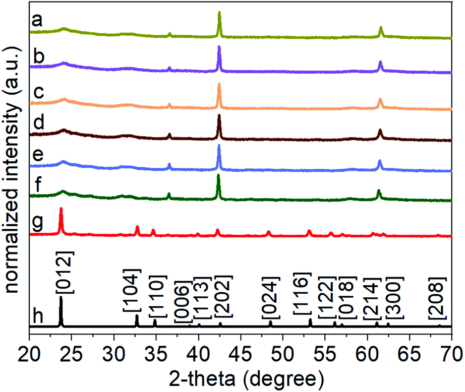 | ||
| Fig. 2 The X-ray diffraction (XRD) patterns for the LiNbO3 product, obtained after a 24 h hydrothermal process, following its heat treatment to: (a) 30 °C; (b) 100 °C; (c) 200 °C; (d) 300 °C; (e) 400 °C; (f) 500 °C; and (g) 600 °C. (h) A reported LiNbO3 reference (ICSD No. 28294) is included for comparison. The diffraction patterns were each normalized by dividing their intensities by the maximum diffraction intensity within each pattern. | ||
We calcined the products obtained after the hydrothermal treatment to crystallize these products. A series of samples were collected following the hydrothermal treatment, each at a distinct duration of the reaction in the autoclave. The calcination step was held constant for each sample by heating the samples to 600 °C for 45 min at an ambient pressure while exposed to air. Purity, crystallinity, and phase of each of these LiNbO3 products obtained following their calcination at 600 °C were analyzed using XRD techniques (Fig. 3). The XRD patterns of the products matched the patterns observed for the rhombohedral structure of LiNbO3 (space group R3c, ICSD No. 28294); all peaks were indexed to the crystalline rhombohedral phase of LiNbO3. These observations further indicated that a calcination step at 600 °C was sufficient to induce crystallization of the LiNbO3 products even when the as-prepared particles were synthesized by a hydrothermal treatment for different periods of time.
 | ||
| Fig. 3 Powder X-ray diffraction (XRD) patterns of calcined LiNbO3 particles, which were originally prepared by hydrothermal reaction times of: (a) 24 h; (b) 48 h; (c) 72 h; and (d) 96 h. Also included are XRD patterns for (e) a reported LiNbO3 reference (ICSD No. 28294). | ||
Size and shape of the products annealed at 600 °C were assessed by TEM and scanning TEM (STEM) techniques. The STEM analyses indicated the hydrothermal treatment and subsequent annealing formed uniform particles with a spherical shape (Fig. 4). The diameters of these particles increased as the hydrothermal reaction progressed from 24 h to 96 h. The average diameter of the LiNbO3 particles obtained after 24 h of hydrothermal treatment was ∼580 nm both before and after calcination (Fig. 4, S5, and S6†). The nominal diameter and spherical shape of the particles did not change following their calcination at 600 °C and the crystallization of the LiNbO3 (Fig. 4 and S6†). The calcination of the particles at 600 °C did, however, transform the solid particles into a porous product as observed in the high-resolution STEM analyses (Fig. 4 and S6†). A series of STEM analyses were performed to assess the pores, their dimensions, and their connectivity within the particles. The STEM images obtained from both high-angle annular dark-field (HAADF) imaging and bright-field imaging show a clear indication of the pores within an otherwise solid particle matrix (Fig. 4 and S6†). According to the International Union for Pure and Applied Chemistry (IUPAC), porous materials are divided into one of three classifications based on their pore size.56 The classifications of porous structures include microporous materials (pore sizes < 2 nm), mesoporous materials (pore sizes between 2 and 50 nm), and macroporous materials (pore sizes > 50 nm).56 The nominal dimensions of the pores within the calcined products were calculated based on the diameter measured from a number of pores as observed by high-resolution STEM imaging. Average diameter of these pores was ∼21 nm, as determined from the STEM analyses (Fig. S7†). Although there could be a large number of pores within each particle due to the three-dimensional (3D) morphology of their matrix, only the projected pores on the perimeters of the calcined particles are easily observed in the STEM images of these mesoporous LiNbO3 particles. Analysis of the particles by 3D tomography is an effective and critical method to identify the actual distribution of pores within these materials. A series of 3D tomographic analyses were performed by TEM techniques to verify the distribution of pores within the calcined particles. A uniform distribution of pores was observed throughout these LiNbO3 particles (Fig. S8 and ESI Video†).
 | ||
| Fig. 4 Scanning transmission electron microscopy (STEM) analyses of LiNbO3 particles obtained by hydrothermal synthesis for (a and b) 24 h; (c and d) 48 h; (e and f) 72 h; and (g and h) 96 h. Each of these products had been calcined at 600 °C for 45 min prior to this analysis by high-angle annular dark-field (HAADF) imaging (a, c, e and g), or bright-field STEM imaging (b, d, f and h). | ||
The diameter of the LiNbO3 particles increased as the hydrothermal reaction progressed from 24 h to 96 h. Average dimensions of the LiNbO3 particles prepared after 48 h, 72 h and 96 h were 1020, 1560 and 1850 nm, respectively. It is worth noting that the porosity of the particles decreases with an increase in the duration of the hydrothermal reaction. For example, the LiNbO3 particles obtained after calcination of the product obtained from the 48 h hydrothermal synthesis contained a smaller volume of pores than those obtained after calcination of the product from a 24 h hydrothermal synthesis. Similarly, the particles obtained after a hydrothermal reaction time of 72 h only exhibited pores along their edges after calcination, while those obtained after a hydrothermal synthesis of 96 h exhibited a denser product with a smoother surface texture. This increase in the diameter coupled with a decrease in porosity of LiNbO3 particles is attributed to a more extensive hydrolysis and condensation of the precursor materials at longer reaction times. The process of hydrolysis and condensation initiates the formation of the LiNbO3 particles. As the reaction progressed, relatively small crystallites of LiNbO3 begin to agglomerate and form progressively larger particles. Growth of the particles with an increase in reaction time proceeds in a controlled manner through a process of dissolution and reprecipitation of agglomerated particles, which progressively form larger primary particles in the solution. The formation of a mesoporous structure within the LiNbO3 particles after calcination is attributed to the base-catalyzed sol–gel reaction that proceeds during the hydrothermal process. The basic conditions of this sol–gel reaction result in the formation of a relatively branched metal oxide species with a more porous network within the resulting particles than those particles prepared from sol–gel reactions catalyzed by acids.56 These branched metal oxide species trap water and residual organic leaving groups from the alkoxide precursors within their porous matrix.56 During calcination, the volatilization of the water and the decomposition of the residual organic moieties (e.g., butoxide groups) coupled with the release of gaseous by-products (e.g., CO2) result in the formation of porous LiNbO3 particles. A decrease in the porosity of the larger LiNbO3 particles is attributed to a further hydrolysis and condensation of the precursors with an increase in the reaction times, which removed unreacted butoxide groups and increased the density of the resulting matrix. These processes lead to the formation of a denser network of Nb–O–Nb bonds within the particles at longer reaction times.
The atomic-scale crystallinity of the mesoporous LiNbO3 particles obtained after 24 h of reaction time was analyzed by high-resolution TEM or HRTEM techniques. Some of the periodic fringe patterns observed by HRTEM for these particles had a spacing of 3.7 Å, which matched the anticipated interplanar spacing of the (012) planes of LiNbO3 (Fig. S9†). Further analysis of the HRTEM images by fast Fourier transform (FFT) (Fig. S9b†) indicated the presence of facets with {012} and {104} orientations when viewed along the ![[4 with combining macron]](https://www.rsc.org/images/entities/char_0034_0304.gif)
![[2 with combining macron]](https://www.rsc.org/images/entities/char_0032_0304.gif) 1 zone axis. We also observed grain boundaries within the porous LiNbO3 particles during the HRTEM analyses, which indicated the aggregative nature of the growth of these products (Fig. S9a†). Overall, the HRTEM analyses indicated the formation of a polycrystalline framework within the porous products. Chemical composition of individual LiNbO3 particles obtained after a reaction time of 24 h was determined by energy-dispersive X-ray spectroscopy (EDS). Dark field TEM-based imaging and elemental maps obtained by EDS analyses of the particles are shown in Fig. S10.† The EDS maps overlaid upon a dark-field image of the particles suggested a uniform distribution of Nb and O within these porous materials. Quantitative EDS mapping of the particles indicated the presence of Nb and O in an atomic ratio of ∼1
1 zone axis. We also observed grain boundaries within the porous LiNbO3 particles during the HRTEM analyses, which indicated the aggregative nature of the growth of these products (Fig. S9a†). Overall, the HRTEM analyses indicated the formation of a polycrystalline framework within the porous products. Chemical composition of individual LiNbO3 particles obtained after a reaction time of 24 h was determined by energy-dispersive X-ray spectroscopy (EDS). Dark field TEM-based imaging and elemental maps obtained by EDS analyses of the particles are shown in Fig. S10.† The EDS maps overlaid upon a dark-field image of the particles suggested a uniform distribution of Nb and O within these porous materials. Quantitative EDS mapping of the particles indicated the presence of Nb and O in an atomic ratio of ∼1![[thin space (1/6-em)]](https://www.rsc.org/images/entities/char_2009.gif) :3, which agreed with the anticipated composition for LiNbO3.
:3, which agreed with the anticipated composition for LiNbO3.
The composition, purity, and crystallinity of the products were further characterized using Raman spectroscopy techniques. The Raman spectra obtained from non-calcined samples provided further support to the assessment that the products obtained following the hydrothermal treatment were semi-crystalline (Fig. S11†).25,27 Characteristic E–TO Raman bands for rhombohedral LiNbO3 were absent in the as-prepared product. These and other characteristic peaks for crystalline LiNbO3 were, however, observed in the Raman spectra of the samples obtained after calcination at 600 °C. These spectra were indexed to the rhombohedral phase of LiNbO3 (Table S1† and Fig. 5). The analysis of a commercial LiNbO3 powder was also included as a reference material. The Raman spectra for the LiNbO3 products obtained after their calcination at 600 °C matched the spectrum for the commercial LiNbO3 powder, which further indicated the formation of a crystalline, rhombohedral phase of LiNbO3.25,27 The Raman bands centered at ∼150 cm−1 can be assigned to the E–TO vibrations of the Nb–O bonds, while Raman bands at ∼225 cm−1 and ∼334 cm−1 are associated with the deformations of NbO6 octahedra. Raman bands at ∼375 cm−1 and ∼430 cm−1 are associated with the E–TO bending modes of the Nb–O–Nb bond. While the Raman band centered at ∼620 cm−1 corresponded to the symmetric stretching of Nb–O–Nb bonds (A1–TO), and the Raman band at ∼870 cm−1 is assigned to the antisymmetric stretching of the Nb–O–Nb bonds in the NbO6 octahedra of LiNbO3.25,27 A Raman band at ∼900 cm−1 was observed for both the non-calcined products (i.e., those obtained directly after the hydrothermal synthesis) and the products after calcination at 600 °C. This band is assigned to a Nb![[double bond, length as m-dash]](https://www.rsc.org/images/entities/char_e001.gif) O stretch. This Raman band is believed to arise from octahedral distortions of surface species such as ONb
O stretch. This Raman band is believed to arise from octahedral distortions of surface species such as ONb![[dash dash, graph caption]](https://www.rsc.org/images/entities/char_e091.gif) OH, which include a double-bond-like behavior and a single elongated NbO bond belonging to a niobium hydroxide based species.25,27 The presence of NbOH bonds on the surfaces of the products prepared using the LiOH·H2O precursor can be attributed to the hydrolysis of the niobium precursor.25,27 The hydrolysis of the Bu–Nb precursor was controlled through a two-step process following its exposure to water vapor and the addition of a solution containing the lithium hydroxide precursor. The degree of hydrolysis of the niobium n-butoxide could be indicated by the presence of the ONbOH species in these materials. It is worth noting that the intensity of this Raman band is higher in the products obtained after a shorter hydrothermal treatment, as well as for those particles with a smaller diameter. The change in the intensity of this band indicated a decrease in the relative amount of ONbOH species in the larger diameter products, which was likely due to a higher degree of condensation within these materials as a result of their prolonged hydrothermal treatment. This higher degree of hydrolysis and condensation results in a transformation of the NbOx(OH)y(OR)z based precursor species to form a more condensed Nb–O–Nb network within the larger particles. This decrease in the intensity of the ONbOH species in these products can also be attributed to the smaller surface area of the larger particles both before and after calcination.25,27 The change in the intensity of the Raman bands associated with the ONbOH species further confirmed our findings related to the evolution of the porosity in the products with prolonged hydrothermal treatment. A smaller contribution of ONbOH species on the surfaces of the larger LiNbO3 particles indicates a higher degree of hydrolysis of the organic protecting groups on the Nb, and the formation of a more condensed Nb–O–Nb network within the product. These attributes correlate with a reduced porosity within the calcined products that were prepared by a prolonged hydrothermal treatment (Fig. 6).
OH, which include a double-bond-like behavior and a single elongated NbO bond belonging to a niobium hydroxide based species.25,27 The presence of NbOH bonds on the surfaces of the products prepared using the LiOH·H2O precursor can be attributed to the hydrolysis of the niobium precursor.25,27 The hydrolysis of the Bu–Nb precursor was controlled through a two-step process following its exposure to water vapor and the addition of a solution containing the lithium hydroxide precursor. The degree of hydrolysis of the niobium n-butoxide could be indicated by the presence of the ONbOH species in these materials. It is worth noting that the intensity of this Raman band is higher in the products obtained after a shorter hydrothermal treatment, as well as for those particles with a smaller diameter. The change in the intensity of this band indicated a decrease in the relative amount of ONbOH species in the larger diameter products, which was likely due to a higher degree of condensation within these materials as a result of their prolonged hydrothermal treatment. This higher degree of hydrolysis and condensation results in a transformation of the NbOx(OH)y(OR)z based precursor species to form a more condensed Nb–O–Nb network within the larger particles. This decrease in the intensity of the ONbOH species in these products can also be attributed to the smaller surface area of the larger particles both before and after calcination.25,27 The change in the intensity of the Raman bands associated with the ONbOH species further confirmed our findings related to the evolution of the porosity in the products with prolonged hydrothermal treatment. A smaller contribution of ONbOH species on the surfaces of the larger LiNbO3 particles indicates a higher degree of hydrolysis of the organic protecting groups on the Nb, and the formation of a more condensed Nb–O–Nb network within the product. These attributes correlate with a reduced porosity within the calcined products that were prepared by a prolonged hydrothermal treatment (Fig. 6).
 | ||
| Fig. 5 Raman spectra for a series of LiNbO3 particles, which were each calcined at 600 °C after their preparation by hydrothermal synthesis for: (a) 24 h; (b) 48 h; (c) 72 h; and (d) 96 h. (e) A Raman spectrum of a commercial LiNbO3 powder included for comparison to the calcined products. | ||
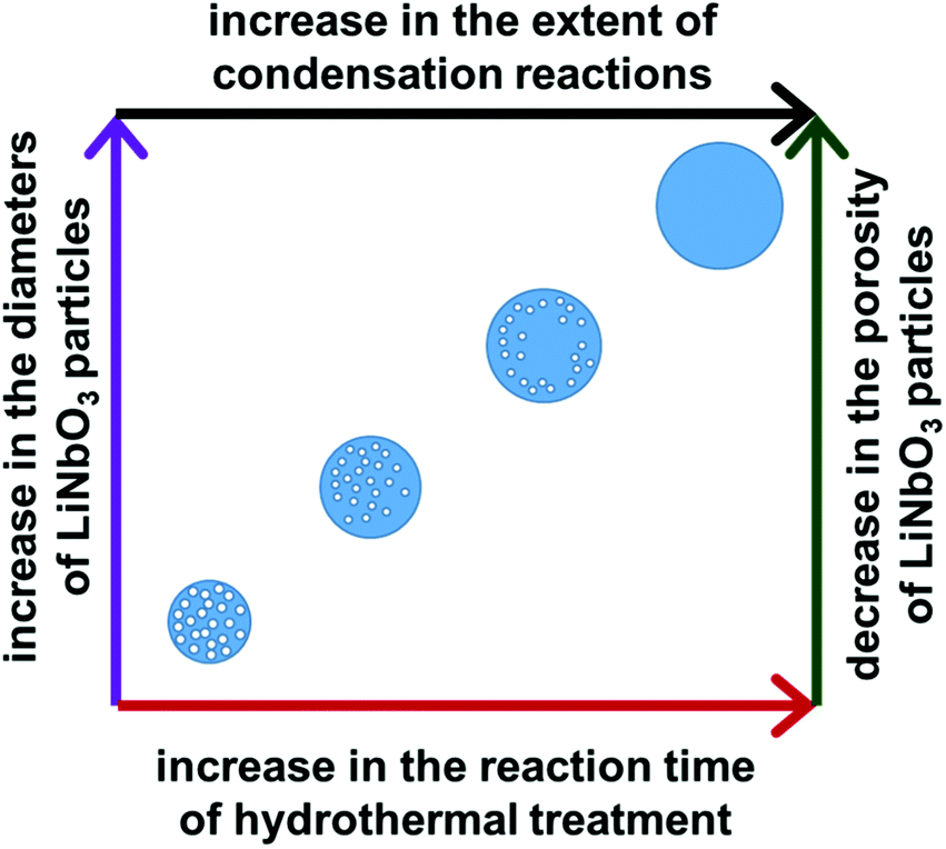 | ||
| Fig. 6 A schematic depiction of correlations between the duration of the hydrothermal treatment of the precursors and the resulting diameter and porosity of the calcined LiNbO3 particles. | ||
We selected the crystalline LiNbO3 particles that resulted from the 24 h hydrothermal treatment and calcination to evaluate their nonlinear optical (NLO) properties. These particles were selected for their relatively high porosity and the degree of disorder within the structure of the particle. Nonlinear optical materials have a wide range of important applications that include quantum light sources, frequency converters, ultrafast optical switches, and memory storage devices.3,57,58 Nonlinear optical processes, such as the generation of a second harmonic response, can be observed when photons of an intense light source interact with the electric fields of an NLO material.30,31,59 Distinct from a medium with a linear optical response, the properties of an NLO material such as its refractive index and absorption coefficient, are dependent on the intensity of the incident light.30,31,59 Second harmonic generation is a second-order NLO process in which two incident photons of the same frequency (ω) are converted into a single photon having double the initial frequency (2ω).30,31,59 The SH signal is produced when the light of a sufficient intensity interacts with a material lacking an inversion symmetry. The oscillating electric field of the incident photons at a particular frequency (ωi) results in a nonlinear polarization of the NLO medium that, upon relaxation, results in the emission of a single photon at twice the incident frequency (2ωi).30,31,59 Unlike a two photon based excitation to induce fluorescence through the transition of electrons to a real excited state, the SHG process is a scattering process that involves the transition to a virtual excited state.30,31,59 The resulting SHG response of the NLO material can be tuned by changing the excitation wavelength. The SH signal intensity observed for NLO materials depends on several factors, such as the properties of both the incident light (e.g., intensity, polarization, and wavelength) and the NLO materials (e.g., dimensions, nonlinear susceptibility).25 The SHG is a nonresonant process that offers flexibility to tune the wavelength of the SH signals by changing the wavelength of the excitation wavelength. Recently, SHG active nanomaterials have received interest for their potential use as probes in SHG based microscopy due to an absence of blinking and a flat frequency conversion response of these nanomaterials, contrary to quantum dots.16,59,60 The NLO materials have also been sought for their ability to generate a coherent emission of light and stability to photoinduced bleaching, contrary to fluorescent dyes.16,59,60 Besides, SHG has proven to be a useful analytical tool for monitoring changes at the interface of NLO materials with biologically relevant systems.18–20
The SHG response of the LiNbO3 particles was evaluated at different incident fundamental wavelengths (FW) using a tunable femtosecond (fs) pulsed laser. The incident FWs were generated using a mode-locked Ti:sapphire laser with a pulse width of ∼140 fs and a tunable output from 680 to 1080 nm. The repetition rate and tuning speed of the fs pulses were 80 MHz and > 40 nm s−1, respectively. The mesoporous LiNbO3 particles were optically transparent across the visible and near-infrared wavelengths with a direct bandgap at 4.77 eV (Fig. S12†). The SHG response for a powdered sample of the porous LiNbO3 particles was assessed for a series of discrete FWs while maintaining a constant incident power. A second harmonic response was detected at 400, 425, 450, 475 and 500 nm (Fig. 7) when the LiNbO3 product was excited with FWs of 800, 850, 900, 950, and 1000 nm, respectively. These results correlated well to the anticipated frequency doubling of the FWs. False-colored images were prepared corresponding to the intensity and wavelength of the SHG response obtained from the powdered LiNbO3 product, as shown in Fig. 7. These results indicated that the porous LiNbO3 particles were SHG active and could generate a second harmonic response over a broad range of wavelengths by adjusting the wavelength of the incident fs pulsed laser. Due to limitations in the configuration of our source and detector, we were limited to studying the NLO properties of these materials over the range from 400 to 500 nm. The SHG of these LiNbO3 particles could be further extended to near- and far-infrared wavelengths by choosing a source of an appropriate incident wavelength. The tunable wavelength and narrow bandwidth of the SHG response from the LiNbO3 particles enable advantages that include generating multiplexed optical images, tuning of the optical response to avoid autofluorescence of the system under study (e.g., cells, tissue), and increasing the depth at which the analysis is performed by minimizing contributions from scattering and absorption.
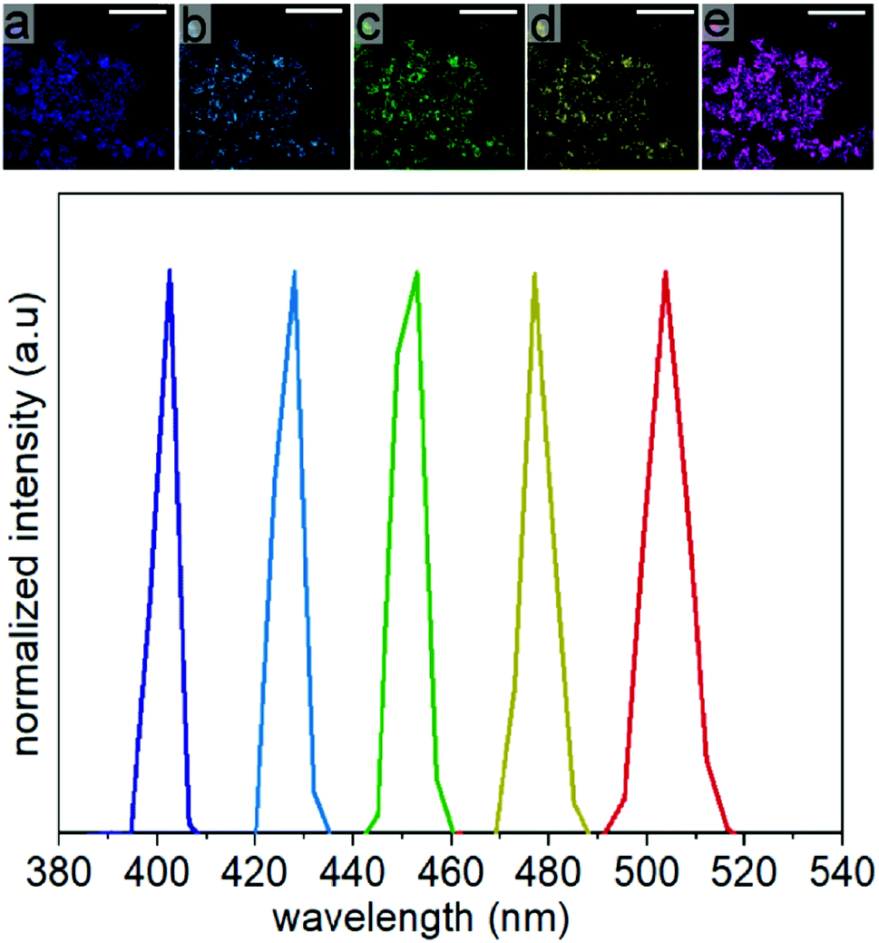 | ||
| Fig. 7 False-colored images of the second harmonic generation (SHG) response for powders of the mesoporous LiNbO3 particles (scale bars = 200 μm). These particles were obtained from the hydrothermal treatment of the precursors for 24 h and calcination of this product at 600 °C. Samples were supported on a glass coverslip, and images of their SHG response were obtained using a pulsed laser excitation at: (a) 800 nm; (b) 850 nm; (c) 900 nm; (d) 950 nm; and (e) 1000 nm. The SH signals collected from the mesoporous LiNbO3 particles confirm their tunable emission at 400, 425, 450, 475 and 500 nm corresponding to the excitation wavelengths indicated for the SHG images in (a) to (e). | ||
Analysis of the polarization dependant SHG of the mesoporous particles can provide further insight into the influence of its crystal structure, structural disorder (e.g., due to both its polycrystallinity or porosity), and potential impurities within these particles on their SHG response.61 The intensity of the SHG response depends on the relative orientation between the polarization of the incoming light and the second-order hyperpolarizability [χ(2)] of an NLO material.62–65 The intensity of the SH signals varies as a function of the polarization of the incident light.62 Lithium niobate is a uniaxial material with a rhombohedral crystal structure at room temperature and a single optical axis, the so-called c-axis.66 Uniaxial minerals are a class of anisotropic minerals that include all minerals within the tetragonal and hexagonal crystal systems. They are referred to as uniaxial because they have a single optical axis or c-axis that can lead to unique optical properties.66 The crystal of LiNbO3, like other uniaxial or anisotropic crystals, has a rotational symmetry with respect to its c-axis.66,67 Lithium niobate is characterized by the threefold rotational symmetry about the crystallographic c-axis and by three mirror planes containing this axis.66,67 Changing the relative orientation between polarization of the incident light and the c-axis of the LiNbO3 crystal can significantly affect the intensity of the resulting SH signal.68,69
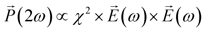
Further characterization of the NLO properties of the LiNbO3 particles was performed by assessing their SHG response as a function of the polarization of the incident laser. The SHG response 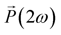 depends on polarization of the incident electric field
  and the nonlinear second-order susceptibility tensor χ2 of the NLO material (eqn (1)).62
 | (1) |
The features described by the χ2 tensor include the crystallographic point group of the NLO material. The rhombohedral phase of LiNbO3 belongs to the 3m crystallographic point group. In addition to the crystal structure, there are many other factors that also influence the χ2 tensor and the SHG response of NLO materials including their dimensions, surface features, and the potential inclusion of dopants. An analysis of the polarization dependent SHG response of a single LiNbO3 particle is one method to further elucidate the potential impacts on the NLO properties of these materials that result from shaping the rhombohedral LiNbO3 into a mesoporous particle.
We evaluated the polarization dependent SHG response of individual LiNbO3 particles under ambient conditions. An SHG-based microscope was utilized to assess the response of individual, isolated particles. The pulsed laser beam from a Ti-sapphire oscillator was focused through a 63× objective onto a single mesoporous LiNbO3 particle. The FW of the incident laser was set to 800 nm with a pulse duration of ∼140 fs, a repetition rate of 80 MHz, and an average power output of 3.2 mW. The direction of polarization of the incident FW was adjusted by rotating a half-wave (HW) plate positioned within the laser path. The SHG response of an individual particle was monitored using a Leica spectrometer equipped with a photomultiplier tube (PMT) to confirm frequency doubling of the FW. A PMT detector was used to collect a series of images of the SHG response from an individual particle as a function of polarization of the incident FW from 0° to 360° with angular steps of 10°. For each polarization, the mean intensity was determined from the corresponding image of the SHG response. For example, Fig. 8a–d depict four SHG images acquired at polarizations of 0°, 90°, 180°, and 270°. The dependence of SHG on polarization of the FW was summarized in an intensity dependent polar plot (Fig. 8e). The plot contained four peaks that were symmetric about 90°. The polar plot has a distinct, symmetric shape in contrast to broad, circular polar plots observed for powdered samples of LiNbO3.70 Due to the subwavelength dimensions of the particles, individual particles can be treated as a dipole oscillating about the c-axis. The shape and symmetry of the polarization dependent response further indicated the formation of SHG active LiNbO3 particles.63
 | ||
| Fig. 8 Images of the SHG response of a single, mesoporous LiNbO3 particle as a function of polarization of the excitation at distinct angles: (a) 0°; (b) 90°; (c) 180°; and (d) 270°. (e) A polar plot of the SHG response (in arbitrary units) generated using an excitation wavelength of 800 nm for a single LiNbO3 particle. This plot shows the dependence of the resulting intensity of the SH on the polarization of the excitation beam. | ||
The polar plot for individual LiNbO3 particles resembled the polarization dependent SHG response of a larger rhombohedral crystal of LiNbO3. The similarity of the features in the polarization dependent response of an individual LiNbO3 particle and a large crystalline substrate strongly suggests a similar dipolar type response. The position and relative intensities of the dipolar-type response within the polar plot are sensitive to the 3D orientation and size of the crystals. Shape and porosity of the particle also impact its angular dependent response.62 The polarization dependent SHG response of the mesoporous LiNbO3 particles could enable their use in differentiating these materials from other substrates (e.g., collagen present in bioimaging applications).71,72 These SHG active materials could also enable the study of advanced NLO processes (e.g., an enhanced SHG response) or the preparation of hybrid materials for controlled drug release and photodynamic therapy through the use of their mesoporous structure.
Conclusions
In conclusion, we demonstrated a sol–gel method using an aqueous solution to prepare uniform, mesoporous LiNbO3 particles with a tunable diameter and porosity. This synthetic approach did not require additional organic species (e.g., surfactants), soft templates (e.g., micelles), or hard templates (e.g., silica or polystyrene beads). This aqueous sol–gel process utilized a hydrothermal treatment that resulted in the in situ formation of niobium hydroxide species, followed by their condensation at higher temperatures in the presence of LiOH to form a network of Nb–O–Nb bonds. A calcination step at 600 °C for 45 min was required to induce crystallization and to create porosity within the products. Diameters of the LiNbO3 particles did not change appreciably before and after this calcination process. Duration of hydrothermal treatment did, however, have a significant effect on both the diameter and porosity of the LiNbO3 particles. Diameter of the calcined particles increased from ∼580 to ∼1850 nm by lengthening the hydrothermal treatment from 24 h to 96 h. In contrast, the longer hydrothermal treatment process yielded LiNbO3 particles with a decreased porosity. The mesoporous LiNbO3 particles were found to be SHG active. Their optical second harmonic response was tuned from 400 to 500 nm by adjusting the wavelength of an incident pulsed laser. The second harmonic response of these particles could be tuned to longer wavelengths with a suitable laser excitation source. Polarization dependent measurements of the SHG response indicated that the mesoporous LiNbO3 particles had a non-centrosymmetric, crystalline structure and exhibited an SHG response similar to that of larger rhombohedral LiNbO3 crystals. These mesoporous, SHG active LiNbO3 particles could be used as optical imaging probes, drug delivery carriers, coatings for electrode materials in Li-ion batteries, photocatalysts, and to investigate the inclusion of materials to enhance their SHG response. The ability to tune the porosity of the LiNbO3 is of particular interest as this increases the available surface area of these particles and also alters transport through these materials. This aqueous sol–gel method to prepare mesoporous, uniform LiNbO3 particles also demonstrates a strong potential for the large-scale synthesis of other mesoporous metal oxides (e.g., Ta2O5, Nb2O5, LiTaO3, BaTiO3).Conflicts of interest
There are no conflicts of interest to declare.Acknowledgements
This work was supported in part by the Natural Sciences and Engineering Research Council of Canada (Discovery Grant No. RGPIN-2020-06522), and through the Collaborative Health Research Projects (CHRP) Partnership Program supported in part by the Canadian Institutes of Health Research (Grant No. 134742) and the Natural Science Engineering Research Council of Canada (Grant No. CHRP 462260), Canada Research Chairs (B. D. Gates, Grant No. 950-215846), and CMC Microsystems (MNT Grant No. 6345). This work made use of 4D LABS (https://www.4dlabs.com) and the Center for Soft Materials shared facilities supported by the Canada Foundation for Innovation (CFI), British Columbia Knowledge Development Fund (BCKDF), Western Economic Diversification Canada, and Simon Fraser University.References
- M. Kösters, B. Sturman, P. Werheit, D. Haertle and K. Buse, Nat. Photonics, 2009, 3, 510–513 CrossRef.
- N. G. R. Broderick, G. W. Ross, H. L. Offerhaus, D. J. Richardson and D. C. Hanna, Phys. Rev. Lett., 2000, 84, 4345 CrossRef CAS.
- K. Buse, A. Adibi and D. Psaltis, Nature, 1998, 393, 665–668 CrossRef CAS.
- W. Yang, P. G. Kazansky and Y. P. Svirko, Nat. Photonics, 2008, 2, 99–104 CrossRef CAS.
- A. Guarino, G. Poberaj, D. Rezzonico, R. Degl'Innocenti and P. Günter, Nat. Photonics, 2007, 1, 407–410 CrossRef CAS.
- B. J. Ash, S. R. Worsfold, P. Vukusic and G. R. Nash, Nat. Commun., 2017, 8, 1–7 CrossRef CAS.
- P. M. Rørvik, T. Grande and M. Einarsrud, Adv. Mater., 2011, 23, 4007–4034 CrossRef.
- D. N. Nikogosyan, Nonlinear Optical Crystals: A Complete Survey, Springer Science & Business Media, 2006, pp. 5–74 Search PubMed.
- R. L. Byer, Annu. Rev. Mater. Sci., 1974, 4, 147–190 CrossRef CAS.
- Y. Kong, F. Bo, W. Wang, D. Zheng, H. Liu, G. Zhang, R. Rupp and J. Xu, Adv. Mater., 2020, 32, 1806452 CrossRef CAS.
- L. Arizmendi, Phys. Status Solidi, 2004, 201, 253–283 CrossRef CAS.
- M. Kauranen, Science, 2013, 342, 1182–1183 CrossRef.
- R. Savo, A. Morandi, J. S. Müller, F. Kaufmann, F. Timpu, M. R. Escalé, M. Zanini, L. Isa and R. Grange, Nat. Photonics, 2020, 14, 740–747 CrossRef CAS.
- J. Li, J. Qiu, W. Guo, S. Wang, B. Ma, X. Mou, M. Tanes, H. Jiang and H. Liu, Nanoscale, 2016, 8, 7416–7422 RSC.
- Y. Wang, X. Y. Zhou, Z. Chen, B. Cai, Z. Z. Ye, C. Y. Gao and J. Y. Huang, Appl. Phys. A, 2014, 117, 2121–2126 CrossRef CAS.
- L. Bonacina, Mol. Pharm., 2013, 10, 783–792 CrossRef CAS.
- A. Barhoumi, B. Salvador-Culla and D. S. Kohane, Adv. Healthc. Mater., 2015, 4, 1159–1163 CrossRef CAS.
- N. Kato, Biophys. Rev., 2019, 11, 1–10 CrossRef.
- B. Moree, G. Yin, D. F. Lázaro, F. Munari, T. Strohäker, K. Giller, S. Becker, T. F. Outeiro, M. Zweckstetter and J. Salafsky, J. Biol. Chem., 2015, 290, 27582–27593 CrossRef CAS.
- P. Hamal, H. Nguyenhuu, V. Subasinghege Don, R. R. Kumal, R. Kumar, R. L. McCarley and L. H. Haber, J. Phys. Chem. B, 2019, 123, 7722–7730 CrossRef CAS.
- H. C. Zeng and S. K. Tung, Chem. Mater., 1996, 8, 2667–2672 CrossRef CAS.
- A. C. Santulli, H. Zhou, S. Berweger, M. B. Raschke, E. Sutter and S. S. Wong, CrystEngComm, 2010, 12, 2675–2678 RSC.
- S. Khalameida, V. Sydorchuk, R. Leboda, J. Skubiszewska-Zięba and V. Zazhigalov, Russ. J. Inorg. Chem., 2014, 59, 419–423 CrossRef CAS.
- X. Zhang, J. Yuan, P. Xia, G. Li, Y. Yu, X. Zhu, Z. Xiong, H. Yu and Y. Xie, Ceram. Int., 2018, 44, 22874–22879 CrossRef CAS.
- R. F. Ali, M. Bilton and B. D. Gates, Nanoscale Adv, 2019, 1, 2268–2275 RSC.
- M. Niederberger, N. Pinna, J. Polleux and M. Antonietti, Angew. Chemie, 2004, 116, 2320–2323 CrossRef.
- R. F. Ali and B. D. Gates, Chem. Mater., 2018, 30, 2028–2035 CrossRef CAS.
- B. D. Wood, V. Mocanu and B. D. Gates, Adv. Mater., 2008, 20, 4552–4556 CrossRef CAS.
- W. Nie, Adv. Mater., 1993, 5, 520–545 CrossRef CAS.
- D. Dini, M. J. F. Calvete and M. Hanack, Chem. Rev., 2016, 116, 13043–13233 CrossRef CAS.
- P. C. Ray, Chem. Rev., 2010, 110, 5332–5365 CrossRef CAS.
- S.-H. Jen, H.-L. Dai and G. Gonella, J. Phys. Chem. C, 2010, 114, 4302–4308 CrossRef CAS.
- C. R. Ma, J. H. Yan, P. Liu, Y. M. Wei and G. W. Yang, J. Mater. Chem. C, 2016, 4, 6063–6069 RSC.
- Y. R. Shen, Nature, 1989, 337, 519–525 CrossRef CAS.
- L. Ghirardini, A.-L. Baudrion, M. Monticelli, D. Petti, P. Biagioni, L. Duò, G. Pellegrini, P.-M. Adam, M. Finazzi and M. Celebrano, J. Phys. Chem. C, 2018, 122, 11475–11481 CrossRef CAS.
- F. Madzharova, Á. Nodar, V. Živanović, M. R. S. Huang, C. T. Koch, R. Esteban, J. Aizpurua and J. Kneipp, Adv. Funct. Mater., 2019, 29, 1904289 CrossRef CAS.
- M. Kauranen and A. V Zayats, Nat. Photonics, 2012, 6, 737–748 CrossRef CAS.
- J. Butet, P.-F. Brevet and O. J. F. Martin, ACS Nano, 2015, 9, 10545–10562 CrossRef CAS.
- N. C. Panoiu, W. E. I. Sha, D. Y. Lei and G. C. Li, J. Opt., 2018, 20, 83001 CrossRef.
- T. Chervy, J. Xu, Y. Duan, C. Wang, L. Mager, M. Frerejean, J. A. W. Münninghoff, P. Tinnemans, J. A. Hutchison and C. Genet, Nano Lett., 2016, 16, 7352–7356 CrossRef CAS.
- S. Debrus, M. K. Marchewka, J. Baran, M. Drozd, R. Czopnik, A. Pietraszko and H. Ratajczak, J. Solid State Chem., 2005, 178, 2880–2896 CrossRef CAS.
- Y. Ren, Z. Ma and P. G. Bruce, Chem. Soc. Rev., 2012, 41, 4909–4927 RSC.
- M. E. Davis, Nature, 2002, 417, 813–821 CrossRef CAS.
- J. Zhang, J. Chen, S. Peng, S. Peng, Z. Zhang, Y. Tong, P. W. Miller and X.-P. Yan, Chem. Soc. Rev., 2019, 48, 2566–2595 RSC.
- X. S. Zhao, J. Mater. Chem., 2006, 16, 623–625 RSC.
- X.-Y. Yang, L.-H. Chen, Y. Li, J. C. Rooke, C. Sanchez and B.-L. Su, Chem. Soc. Rev., 2017, 46, 481–558 RSC.
- Y. Liu, J. Goebl and Y. Yin, Chem. Soc. Rev., 2013, 42, 2610–2653 RSC.
- D. Wang and F. Caruso, Adv. Mater., 2003, 15, 205–210 CrossRef CAS.
- M. Sohmiya, S. Umehara, S. Enomoto, Y. Ide, T. Okada, Y. Sugahara and M. Ogawa, Nanoscale Adv, 2019, 1, 1726–1730 RSC.
- L. Zhao, M. Steinhart, M. Yosef, S. K. Lee, T. Geppert, E. Pippel, R. Scholz, U. Gösele and S. Schlecht, Chem. Mater., 2005, 17, 3–5 CrossRef CAS.
- N. Y. Turova, E. P. Turevskaya, V. G. Kessler and M. I. Yanovskaya, Chem. Met. Alkoxides, 2002, 107–125 Search PubMed.
- D. C. Bradley, Chem. Rev., 1989, 89, 1317–1322 CrossRef CAS.
- N. Y. Turova, E. P. Turevskaya, V. G. Kessler and M. I. Yanovskaya, The chemistry of metal alkoxides, Springer Science & Business Media, 2006, pp. 107–115 Search PubMed.
- D. C. Bradley, Philos. Trans. R. Soc. London. Ser. A, Math. Phys. Sci., 1990, 330, 167–171 CAS.
- M. Horn and U. Horns, Alkoxides, Metal, in Kirk-Othmer Encyclopedia of Chemical Technology, 4th edn, 2000, vol. 2, pp. 21–29 Search PubMed.
- B. Zdravkov, J. Čermák, M. Šefara and J. Janků, Open Chem, 2007, 5, 385–395 CAS.
- B. Corcoran, C. Monat, C. Grillet, D. J. Moss, B. J. Eggleton, T. P. White, L. O'Faolain and T. F. Krauss, Nat. Photonics, 2009, 3, 206–210 CrossRef CAS.
- K. Nozaki, A. Shinya, S. Matsuo, Y. Suzaki, T. Segawa, T. Sato, Y. Kawaguchi, R. Takahashi and M. Notomi, Nat. Photonics, 2012, 6, 248–252 CrossRef CAS.
- W. P. Dempsey, S. E. Fraser and P. Pantazis, BioEssays, 2012, 34, 351–360 CrossRef CAS.
- P. Pantazis, J. Maloney, D. Wu and S. E. Fraser, Proc. Natl. Acad. Sci. U. S. A., 2010, 107, 14535–14540 CrossRef CAS.
- Q. Xiao, W. Lin, G. Chen, C. Ding, G. Dong, C. Lin, B. Wu, E. Wu, H. Zeng and J. Qiu, J. Mater. Chem. C, 2015, 3, 4070–4076 RSC.
- E. Kim, A. Steinbrück, M. T. Buscaglia, V. Buscaglia, T. Pertsch and R. Grange, ACS Nano, 2013, 7, 5343–5349 CrossRef CAS.
- F. Timpu, J. Sendra, C. Renaut, L. Lang, M. Timofeeva, M. T. Buscaglia, V. Buscaglia and R. Grange, ACS Photonics, 2019, 6, 545–552 CrossRef CAS.
- J. R. W. Ulcickas and G. J. Simpson, Advanced Chemical Microscopy for Life Science and Translational Medicine, SPIE, 2020, vol. 11252, pp. 1–9 Search PubMed.
- K. Y. Raygoza-Sánchez, I. Rocha-Mendoza, P. Segovia, A. V Krasavin, G. Marino, T. Cesca, N. Michieli, G. Mattei, A. V Zayats and R. Rangel-Rojo, Sci. Rep., 2019, 9, 1–9 Search PubMed.
- R. S. Weis and T. K. Gaylord, Appl. Phys. A, 1985, 37, 191–203 CrossRef.
- M. Sumets, Lithium Niobate-Based Heterostructures, IOP Publishing, 2018, pp. 4–65 Search PubMed.
- A. Sergeyev, R. Geiss, A. S. Solntsev, A. A. Sukhorukov, F. Schrempel, T. Pertsch and R. Grange, ACS Photonics, 2015, 2, 687–691 CrossRef CAS.
- R. Grange, J.-W. Choi, C.-L. Hsieh, Y. Pu, A. Magrez, R. Smajda, L. Forró and D. Psaltis, Appl. Phys. Lett., 2009, 95, 143105 CrossRef.
- O. Sánchez-Dena, Z. Behel, E. Salmon, E. Benichou, J.-A. Reyes-Esqueda, P.-F. Brevet and C. Jonin, Opt. Mater., 2020, 107, 110169 CrossRef.
- A. Zoumi, A. Yeh and B. J. Tromberg, Proc. Natl. Acad. Sci. U. S. A., 2002, 99, 11014–11019 CrossRef CAS.
- C.-A. Couture, S. Bancelin, J. Van der Kolk, K. Popov, M. Rivard, K. Légaré, G. Martel, H. Richard, C. Brown and S. Laverty, Biophys. J., 2015, 109, 2501–2510 CrossRef CAS.
Footnote |
| † Electronic supplementary information (ESI) available: Additional optical images of the aqueous sol–gel process, X-ray diffraction (XRD) data, transmission electron microscopy (TEM) and scanning TEM (STEM) data, TEM tomography data and video, pore size analyses, energy-dispersive X-ray spectroscopy (EDS) results, Raman spectroscopy data, and an extinction spectrum of the LiNbO3 particles. See DOI: 10.1039/d1ra07216a |
| This journal is © The Royal Society of Chemistry 2022 |