 Open Access Article
The synthesis and properties of isocyanate-based polyimide foam composites containing MWCNTs of various contents and diameters
Xinyu Xu *,
Jingjing Cao,
Yudi Zhang,
Fukai Yang and
Yuyuan Deng*
School of Petrochemical Engineering, Liaoning Petrochemical University, Fushun 113001, Liaoning, China. E-mail: xuxinyu_2012@163.com; dengyylnpu@126.com
First published on 16th February 2022
Abstract
Polyimide foams (PIFs) were synthesized using in situ polymerization from poly((phenyl isocyanate)-co-formaldehyde) (PAPI), pyromellitic dianhydride (PMDA), and multi-walled carbon nanotubes (MWCNTs) (0.05, 0.1, 0.2, 0.4, and 0.6 wt%) functionalized with –OH; the diameters were 10–20 nm, 20–30 nm, and >50 nm. The morphology, mechanical properties, and flame retardancy of the composites made from MWCNTs with different contents and diameters were studied. The effects of different contents of MWCNT on the properties of composites were compared. SEM results show that the pore morphology of PIF was not damaged when the content of the MWCNTs was low due to crosslinking between MWCNTs and amide bonds. When the content of the MWCNTs was high, the vacuoles of PIF became large and uneven. Compared to pure PIF, mwCNT-1 (0.2% MWCNT content) significantly increased the compressive strength (330%) and compression modulus (210%) of PI. Due to the significant thermal stability of PIF/MWCNTs, the degradation temperature of PIF/MWCNT-1 (0.2% MWCNT content) was increased from 302 °C to 321.5 °C upon addition of MWCNTs. The effects of different diameters of MWCNTs on the morphology and properties of the PIF/MWCNT composites were also compared. The morphology, thermal stability, and mechanical properties of the composites containing smaller MWCNTs were higher than those of composites containing larger MWCNTs. This is because MWCNTs act as nucleating agents to promote the formation and growth of bubbles. Smaller diameters of MWCNTs lead to higher MWCNT contents in the unit volume and more nucleation points of MWCNTs in the PIF. An increasing MWCNT diameter leads to a gradually decreasing number of bubbling nucleation centers. The LOI of PIF/MWCNTS increased with increasing MWCNT due to the nitrogen heterocyclic interaction between the PIF and MWCNTS. The diameter of MWCNTS had only a minor effect on the flame retardancy.
1 Introduction
Polyimide foams (PIFs) are high-performance polymers due to the presence of imide rings in the molecular skeleton. They are light weight, chemically stable, absorb heat and sound, and have been widely used in the aerospace industry. However, the mechanical properties of traditional polyimide foams are weak, which limits their application in some fields.1–3 PIF containing isocyanate has attracted increasing attention because of its simple preparation process and reasonable equipment requirements. The isocyanate group, however, tends to react with the amino group (the product of water (H2O) and isocyanate reaction) to form an urea group in the foaming process. The urea group causes the isocyanate group of PIFs to have poor flame retardancy and thermal stability.4Inorganic fillers in PIF materials, including montmorillonite,5 graphene,6 graphene oxide,4,7 silicon carbide,8 carbon nanofibers,9 and carbon nanotubes,10–17 can affect the pore structure and morphology of the foam and significantly improve the thermal stability and mechanical properties of the foam composites. Carbon nanotubes (CNTs) are widely used in polymer composites because of their high aspect ratio, high mechanical strength and modulus, excellent chemical stability, and good electrical conductivity.10–12 The introduction of carbon nanotubes into a polymer matrix can improve the material's mechanical, electrical, thermal, and morphological properties. However, the strong van der Waals interactions cause CNTs to aggregate. Thus, good dispersion of nanomaterials in the polymer matrix is essential for improving the properties of the composites. CNTs can be divided into single-walled CNTs and multi-walled CNTs. The diameter of single-walled CNTS (SWCNTs) is very small, and their specific surface energy is very high; they exist in bundles. Multi-walled carbon nanotubes (MWCNTs) are composed of SWCNTs with different diameters and are generally larger than SWCNTS; thus, they are better dispersed when mixed with polymers.
Several methods are used to solve the agglomeration problem in polymer–CNT composites including in situ polymerization, adding compatibilizers, and surface modification of carbon nanotubes. Coupling of the polymer–CNT interface or CNT–CNT interface, as well as coaxial sliding of the inner wall of the CNTs, leads to energy dissipation when CNTs are embedded in the polymer matrix. The interfacial adhesion and dispersion morphology of the CNT/polymer determines polymer–CNT sliding.2,10–15 The CNT content determines the sliding between CNT and CNT. Coaxial slipping between CNT tube walls does not result in a significant increase in loss factors but does reduce the threshold of the strain level, thus leading to a stick-slip dissipation.2,13
Roohollah et al.12 prepared PI/modified MWCNT composites containing 0.5, 1, 3, and 5 wt% functionalized MWCNT using in situ reactions. The addition of MWCNTs improves the thermal stability of the composites. The morphology shows that MWCNTs are evenly distributed in the polymer matrix, improving the mechanical properties of the nanocomposites. Yang et al.14 developed an effective method to prepare microporous polyimide (PI)/RGO/MWCNT nanocomposites. The synergistic effect of RGO and MWCNTs enhances the conductivity and EMI shielding performance of the nanocomposites. When the amount of GO and MWCNTs was 8 wt%, the EMI SE value of the PI/RGO/MWCNT nanocomposites was 755–823 dB cm2 g−1. The thermal stability was also improved, and Young's modulus reached the highest value. Wang et al.16 studied GO/CNT nano-fillers cross-linked by amide bonds and introduced them into a PI matrix. The dispersion of nano-fillers in PI was improved due to the strong interfacial interactions between nano-fillers and the PI matrix. The strength, modulus, fracture toughness, and electrical conductivity of the PI matrix are increased by 118%, 94%, 138%, and 11 orders of magnitude, respectively, when the GO/CNT content of amide bond hybridization is 1.1 wt%.
Most researchers focus on the effect of MWCNT content on the morphology and properties of PI nanocomposites. Importantly, factors that affect the material properties include not only the content of the filler, but also the structure and size of the filler. As such, the effects of MWCNT content and diameter on the morphology, structure, and properties of PI composites were analyzed in this paper. PIF/MWCNT composite foams were prepared by in situ polymerization of MWCNTs [containing –OH with different diameters (10–20 nm, 20–30 nm, 30–50 nm, and >50 nm)], PMDA, and PAPI. The effects of the same diameter and different contents (0.05–0.6%) of MWCNTs on the morphology, mechanical properties, thermal stability, and flame retardancy properties of the composites were compared. We also compared the effects of MWCNTs with different diameters on the mechanical and flame–retardant properties.
2 Experimental section
2.1 Materials
PMDA was purchased from Shanghai Bangcheng Chemical Co., Ltd. PAPI (44V20) and AK8805 were produced by Shandong Wanhua Chemical Co., Ltd. The amine catalyst (TEA) and polyethylene glycol-600 (PEG-600) were purchased from Guangzhou Suixin Chemical Co., Ltd. Tin catalyst (T9) was purchased from Shandong Baiqian Chemical Co., Ltd. CH3OH and DMF were purchased from Tianjin Fuyu Fine Chemicals Co., Ltd. Purified water was used as a chemical foaming agent. Hydroxylated MWCNTs were developed by Beijing Deke Dao Gold Technology Co., Ltd.2.2 Preparation of MWCNT/PIF composites
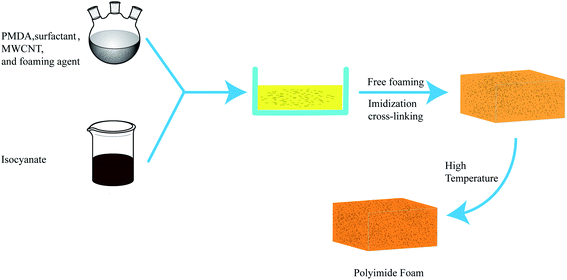
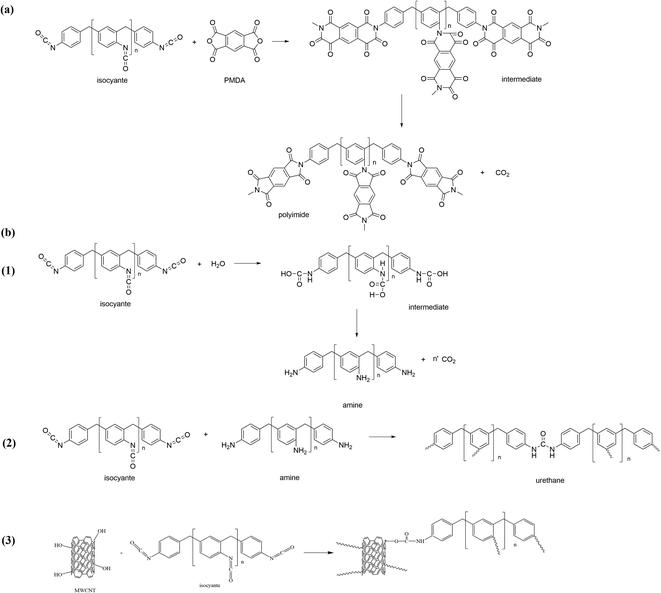
Fig. 1 and Scheme 1 show the synthesized PI and PIF/MWCNT. Here, an ultrasonic vibration method was used to improve the dispersion of MWCNT in situ during polymerization. Taking the PIF/MWCNT-1 composite material as an example, DMF was first weighed and placed in the reactor. We then added MWCNTs that were 10–30 μm long and 10–20 nm in diameter: MWCNT-1-0.05, MWCNT-1-0.1, MWCNT-1-0.2, MWCNT-1-0.4, and MWCNT-1-0.6 (Table 2). PMDA was used as the standard amount for formulation.MWCNTs were dispersed in DMF by the ultrasonic equipment for 40 min at 20 °C. TEA, T9, H2O, CH3OH, silicone surfactant (AK8805) and PEG-600 were weighed in turn according to the dosage shown in Table 1 and placed in the reaction container. Next, 20 g PMDA was added while stirring at 20 °C. After the PMDA was completely dissolved, the temperature of the mixed solution was increased to 80–100 °C for 30 min of reaction. The temperature of the solution was then reduced to about 25 °C. The resulting solution was the precursor solution.
| Chemical | Part by weight (wt%) |
|---|---|
| PMDA | 20 |
| Isocyanate (PAPI) | 20 |
| Amine catalyst (TEA) | 0.6 |
| Tin catalyst (T9) | 0.4 |
| CH3OH | 2.4 |
| H2O | 2.8 |
| PEG-600 | 15 |
| Silicone surfactant (AK8805) | 5 |
| DMF | 20 |
| Sample | Diameter MWCNT (nm) | Long MWCNT (μm) | MWCNT content (wt%) | OH– content of MWCNT (wt%) |
|---|---|---|---|---|
| Neat PIF | — | — | 0 | 0 |
| PIF/MWCNT-1-0.05 | 10–20 | 10–30 | 0.05 | 3.06 |
| PIF/MWCNT-1-0.1 | 10–20 | 10–30 | 0.1 | 3.06 |
| PIF/MWCNT-1-0.2 | 10–20 | 10–30 | 0.2 | 3.06 |
| PIF/MWCNT-1-0.4 | 10–20 | 10–30 | 0.4 | 3.06 |
| PIF/MWCNT-1-0.6 | 10–20 | 10–30 | 0.6 | 3.06 |
| PIF/MWCNT-2-0.05 | 20–30 | 10–30 | 0.05 | 1.76 |
| PIF/MWCNT-2-0.1 | 20–30 | 10–30 | 0.1 | 1.76 |
| PIF/MWCNT-2-0.2 | 20–30 | 10–30 | 0.2 | 1.76 |
| PIF/MWCNT-2-0.4 | 20–30 | 10–30 | 0.4 | 1.76 |
| PIF/MWCNT-2-0.6 | 20–30 | 10–30 | 0.6 | 1.76 |
| PIF/MWCNT-3-0.05 | >50 | 10–30 | 0.05 | 0.71 |
| PIF/MWCNT-3-0.1 | >50 | 10–30 | 0.1 | 0.71 |
| PIF/MWCNT-3-0.2 | >50 | 10–30 | 0.2 | 0.71 |
| PIF/MWCNT-3-0.4 | >50 | 10–30 | 0.4 | 0.71 |
| PIF/MWCNT-3-0.6 | >50 | 10–30 | 0.6 | 0.71 |
The precursor solution was mixed with PAPI at a mass ratio of 1![[thin space (1/6-em)]](https://www.rsc.org/images/entities/char_2009.gif) :
:![[thin space (1/6-em)]](https://www.rsc.org/images/entities/char_2009.gif) 1 and stirred on high speed. When the mixed solution began to turn white, it was quickly poured into an open mold and foamed freely to obtain an intermediate foam. After curing at room temperature for 2–4 h, the foam intermediate was put into an oven filled with nitrogen for an amidation reaction at 220 °C for 2 h before use.12–16
1 and stirred on high speed. When the mixed solution began to turn white, it was quickly poured into an open mold and foamed freely to obtain an intermediate foam. After curing at room temperature for 2–4 h, the foam intermediate was put into an oven filled with nitrogen for an amidation reaction at 220 °C for 2 h before use.12–16
A brief description of the preparation process is shown in Fig. 1. Scheme 1 also shows the reaction mechanism of PAPI and MWCNTs in the composite material. Each formulation consists of one primary reaction and three side reactions. Chemical reactions during the preparation process are displayed in Scheme 1. PMDA reacts with PAPI to generate the intermediate product that is imidized at 220 °C. Water is used as a foaming agent (Scheme 1(b1)). Inevitably, the side reaction of the isocyanate with the amino produces the urea group shown in Scheme 1(b2). Scheme 1(b3) shows the hydroxyl reaction of PAPI and MWCNT.
2.3 Characterization methods
The Fourier transform infrared (FTIR) spectra of the samples were tested with a Nexus-470 spectrometer (Thermo Nicolet Instruments, Newcastle, DE, USA). The ATR scanning method was used to scan the infrared spectrum of the sample surface from 500–4000 cm−1.The apparent density of PIFs was determined according to ISO 845:2006. Cubes (50 mm × 50 mm × 50 mm) were cut as specimens and at least five cubes for each sample were measured. An electronic balance with an accuracy of 0.0001 g was used to weigh the mass of each sample and calculate the apparent density.
Scanning electron microscopy (SEM) was completed on a Hitachi SU8010 (Japan). The test voltage was adjusted to 15–20 kV, and the lens magnification values were 40×, 50×, and 100×.
A TG209F3 thermogravimetric analyzer (Germany) was used for further analysis. The system requires a constant temperature and a stable 220 V power supply at 10 A. After starting calibration, the inert gas is pumped into the circulation three times to remove oxygen in the reaction chamber. In this experiment, nitrogen was used as the atmosphere gas. The PI foam material was cut into blocks and placed in an Al2O3 crucible. The temperature change rate was 10 °C min−1 from 25 °C to 800 °C at room temperature, which was used to start the test.
The microcomputer controlled electronic universal testing machine WDS-10G was used to test the compression strength. According to the ISO 844:2004 standard, the required size of the cube was 50 mm × 50 mm × 50 mm, and each sample needed five samples. During this test, the pressure sensor of the testing machine moves at a constant speed perpendicular to the direction of the supporting surface. The motion speed of the pressure sensor is 5 mm min−1, and the compression thickness is 85%. The pressure number at this time is recorded.
The limit oxygen index (LOI) test was performed using a FTT0082 Fire Testing Technology in accordance with ISO 4589-2:1996. The specimen size was 120 × 10 × 10 mm (length × width × thickness).
3 Results and discussion
3.1 Chemical structures of PIF and PIF/MWCNT
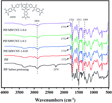
The FTIR curves of the PIF before post-curing, PIF, PIF/MWCNT-1-0.05, PIF/MWCNT-1-0.2, and PIF/MWCNT-1-0.6 after post-curing are shown in Fig. 2. The stretching vibration characteristic peak of the –NH2 group generated by the reaction of isocyanate with water is 3388 cm−1. The skeleton vibration characteristic peak of benzene ring in PAPI is at 1511 cm−1. The imine carbonyl is characteristically adsorbed at 1772 cm−1 (asymmetric C–O stretching) and 1723 cm−1 (symmetric C–O stretching). The –NCO absorption peak near 2265 cm−1 disappears after curing, and asymmetric C–O stretching near 1772 cm−1 appears as shown in the PIF before post-curing and PIF. This is due to the imination reaction.The FTIR spectra of PIF/MWCNT-1-0.05, PIF/MWCNT-1-0.2, and PIF/MWCNT-1-0.6 show no isocyanate absorption peak at 2265 cm−1, indicating that all PAPI reactions occurred in the first solution.8 The peaks at 2856 cm−1 are caused by vibrations formed by the –CH2 – and –CH – chains in the anhydride and isocyanate groups, respectively. The peak at 1369 cm−1 corresponds to the C–N stretching vibration of the imine ring. Inverse bending of the imine ring vibration was observed at 724 j cm−1. The curves of the infrared spectrum show that PIF was successfully prepared. The MWCNT content was 0.05, 0.2, and 0.6 wt%. No new characteristic peaks appeared in the FTIR curves of the composites. The introduction of MWCNTs has no effect on the molecular structure of PIFS.17–19
The characteristic vibration of the isocyanate groups in the uncured PI indicates that there may be an excess of isocyanate groups in the foam (Fig. 2). Excess isocyanates may react with H2O or self-polymerize. The cell size may increase when the MWCNT content increases from 0.05 to 0.6 wt% because of the complete reaction and the generation of carbon dioxide (CO2). Changes in bubble size may also affect changes in foam density as observed by SEM.20–22
3.2 Morphology characterization of PIF and PIF/MWCNT composites
The average cellular diameter and density of PIF and PIF/MWCNT are shown in Table 3. The three PIF/MWCNT composites show the same trend. The cellular diameter of PIF/MWCNT was larger than that of neat PIF. The addition of MWCNT-1 increased the average cell size to 595 μm for MWCNTs at 0.05 wt%. For PIF/MWCNT, the cellular diameter of the foam first decreased (528 μm for 0.2 wt%) and then increased (684 μm for 0.6 wt%) when the MWCNT content increased gradually. The average cell size increased to 557 and 536 μm for MWCNT-2 and MWCNT-3, respectively, at the same filler loading (0.2 wt%). However, the density of the composites showed the opposite trend: it first increased (11.69 kg m−3 for 0.2 wt%) and then decreased (10.56 kg m−3 for 0.6 wt%). Generally, the factors affecting the density include the size of the bubble and the composition of the matrix. A larger bubble size implies a smaller density. However, the density of the foam increases with increasing MWCNT content due to the high density of the MWCNTs. The density data show that the density of the composites decreased with increasing MWCNT dosage because it increases the pore size of the foam.| Content of MWCNTs (%) | Mean cellular diameter | Apparent density | ||||
|---|---|---|---|---|---|---|
| PIF/MWCNT-1 (μm) | PIF/MWCNT-2 (μm) | PIF/MWCNT-3 (μm) | PIF/MWCNT-1 (kg m−3) | PIF/MWCNT-2 (kg m−3) | PIF/MWCNT-3 (kg m−3) | |
| 0 | 435 | 435 | 435 | 12.16 | 12.16 | 12.16 |
| 0.05 | 595 | 554 | 573 | 9.84 | 10.08 | 9.58 |
| 0.1 | 544 | 538 | 557 | 10.08 | 10.64 | 9.95 |
| 0.2 | 528 | 554 | 566 | 11.69 | 11.52 | 10.72 |
| 0.4 | 572 | 594 | 647 | 10.98 | 10.00 | 10.46 |
| 0.6 | 684 | 665 | 685 | 10.56 | 9.68 | 10.00 |
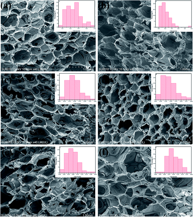
Fig. 3 shows that the cell is in the solid phase, and the edge of the cell is connected to the cell surface with space or gas phases presenting an open cell form. Most PIF cells are hexagonal cells. Fig. 3b–d show that the mean diameter of the cells was more uniform upon addition of MWCNT-1 (0.05–0.2 wt%) in Fig. 4 (×100). There are many membrane structures in the cell network structure of PIF/MWCNT-1 composites. These characteristics support the cell wall and may maintain the stability of the cell structure and the morphology of the composite material. This is due to the in situ polymerization of the isocyanates with the hydroxyl groups of MWCNTs. This in turn reduces the surface tension of the flexible PIFs and MWCNTs.1,15,16 At the same time, MWCNTs act as nucleating agents to make the structure of the cell network more uniform.12,13,17 An increase in the content of MWCNTs, as shown in Fig. 3e and f, causes the hexagonal shape to become more irregular and larger. Therefore, the incorporation of integrative cells—especially the higher fillers—destroys the homogeneous cellular structure due to the increase in MWCNT content. We conclude that the addition of MWCNTs affects the size and structure of the pores.
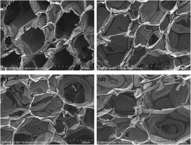 | ||
| Fig. 4 SEM images of PIF and PIF/MWCNT-1 with different contents: (a) PIF; (b) 0.05 wt% MWCNTs; (c) 0.2 wt% MWCNTs; (d) 0.6 wt% MWCNTs (100×). | ||
Gas is generated during the reaction process due to the reaction of MWCNTs, polyols, and H2O with isocyanates. This rapidly increases the intracellular pressure. Thus, the entire cell structure can be destroyed when the cell wall is unable to withstand the internal pressure. This allows the gas to escape and form a larger cellular structure. At the same time, the self-agglomeration will also affect the uneven spread of gas generated in the foaming process when the MWCNT content is high; this leads to a more heterogeneous cell size.4,23–25
Fig. 5 shows the morphologies and average pore sizes of PIF/MWCNT with the same MWCNT content (0.2 wt%) and different diameters. The average pore size of PIFs with added MWCNTs was larger than pure PIFs. The membrane structures of the cells are all present. The cell size of PIF/MWCNT also increased slightly as the diameter of MWCNTs increased (Table 3). This is because the smaller diameter of MWCNTs causes more MWCNTs per unit volume. Therefore, MWCNT nucleating agents can promote the formation and growth of bubbles. The number of bubbling nucleation centers decreases gradually as the diameter of MWCNTs increases. Therefore, the cell size of the composites is large and uneven.
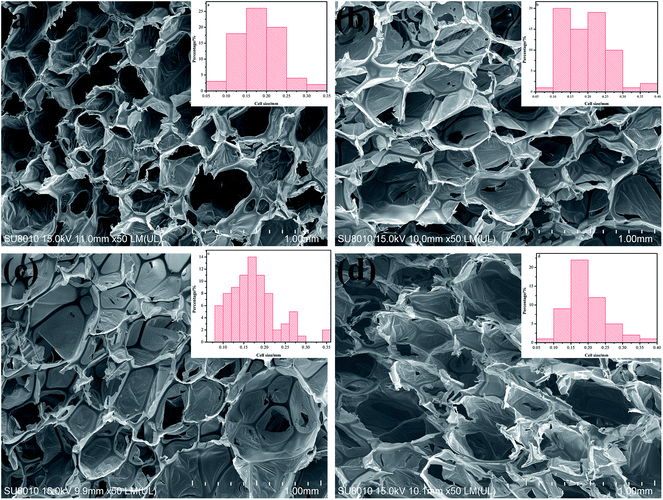 | ||
| Fig. 5 SEM images of PIF and PIF/MWCNT with different diameters: (a) PIF; (b) 10–20 nm MWCNTs; (c) 20–30 nm MWCNTs; (d) >50 nm MWCNTs (50×). | ||
3.3 Thermogravimetric analysis
The TGA curves of the PIF/MWCNT composites are displayed in Fig. 6 and the thermal data (Td5% and R800) are outlined in Table 4. Two distinct peaks can be observed for PIF/MWCNT-1, PIF/MWCNT-2, and PIF/MWCNT-3 in Fig. 6. The TGA curves of all PIFs are at 430 °C and 600 °C relative to the degradation temperatures of some amino or unstable parts (e.g., the ureido of the main ring of imines at high thermal decomposition temperatures). A higher content of MWCNTs leads to a higher thermal stability leaving more residue in thermal decomposition. The 5% weightlessness temperature (Td5%) increases with more MWCNT packing. These data indicate that MWCNTs can significantly improve the thermal stability of PIFs.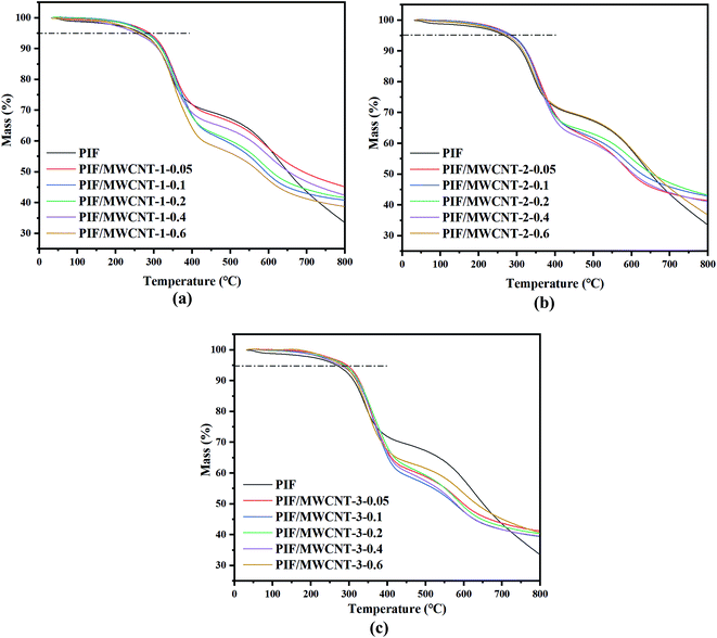 | ||
| Fig. 6 TGA curves of PIF and PIF/MWCNT with different diameters: (a) 10–20 nm MWCNTs; (b) 20–30 nm MWCNTs; (c) >50 nm MWCNTs. | ||
| Content of MWCNTs (%) | Td5% | R800 | ||||
|---|---|---|---|---|---|---|
| PIF/MWCNT-1 (°C) | PIF/MWCNT-2 (°C) | PIF/MWCNT-3 (°C) | PIF/MWCNT-1 (%) | PIF/MWCNT-2 (%) | PIF/MWCNT-3 (%) | |
| 0 | 302.0 | 302.0 | 302.0 | 33.65 | 33.65 | 33.65 |
| 0.05 | 321.5 | 320.0 | 315.5 | 45.24 | 43.26 | 39.72 |
| 0.1 | 318.0 | 317.8 | 312.6 | 42.44 | 42.35 | 39.25 |
| 0.2 | 315.6 | 314.5 | 310.5 | 41.67 | 41.49 | 38.46 |
| 0.4 | 312.9 | 313.6 | 308.0 | 41.36 | 41.17 | 38.15 |
| 0.6 | 308.2 | 306.5 | 306.2 | 38.80 | 36.90 | 37.75 |
There are two reasons for the high thermal stability of PIF/MWCNT composites: (1) polymer degradation begins with the cleavage of chains and the formation of free radicals. The carbonaceous surface of the MWCNTs can be used as a free radical scavenger to help delay the initial temperature of PIF degradation and improve its thermal stability. Meanwhile, a high MWCNT content improves the thermal conductivity of PIF/MWCNT, which is useful for heat dissipation. This partly improves the thermal stability of PIF/MWCNT.9,10 (2) The excellent thermal stability is attributed to the strong chemical bond between the MWCNTs and the PI chain, which physically inhibits the motion of the PI molecular chain. Therefore, heat may be quickly transferred from PI chains to MWCNTs when exposed to high temperatures. The high thermal conductivity and excellent thermal stability gives the aerogels the ability to withstand external heat. The char yield and thermal stability increase with cross-linking, thus making these materials suitable for high temperature applications.9
These data indicate that the polyimide foam studied in this paper has excellent thermal stability, and the incorporation of MWCNTs further enhances this effect. MWCNTs have excellent thermal insulation performance and high temperature stability. At high temperatures, fillers can impede heat transfer during bulk foam processes. In general, inorganic fillers can facilitate heat transfer to the polymer chain, prevent heat diffusion, and limit further degradation of inorganic fillers on the thermal decomposition process of volatile products. Fillers impact the effect and quality of transport barriers and can delay thermal degradation. In addition, the enrichment of MWCNTs packing in the bubble surface can act as an insulating layer when the lateral polyimide degrades; this can protect the internal foam from thermal degradation. Thus, the residual weight of the composite is up 40% even if the MWCNT content is small.11,26–29
Table 4 shows the Td5% and R800 of the PIF/MWCNT with different diameters. The Td5% and R800 of the PIF/MWCNT-1 are better than that of PIF/MWCNT-2, which is better than that of PIF/MWCNT-3. The SEM results show consistent results. In foam composites, a smaller diameter of MWCNT leads to more MWCNT per unit volume. In general, MWCNTs act as thermal barriers to transfer heat to the polymer chain, thereby preventing rapid transfer of heat and limiting further degradation.12 In addition, more inorganic fillers act as a better barrier to the volatile products produced during thermal decomposition. This hinders thermal degradation.13 Therefore, when the outer polyimide is degraded, more filler accumulates on the surface of the foam and acts as an insulating layer to protect the internal foam from degradation.
3.4 Mechanical properties
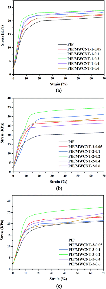
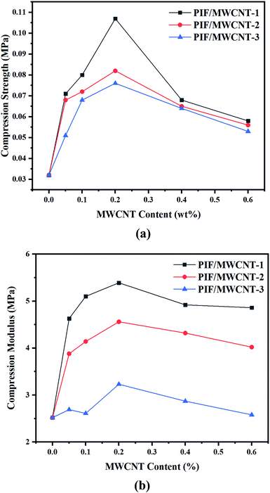
The compression stress–strain curve of PIF/MWCNT is shown in Fig. 7, and the specific changes in compression strength and compression modulus at 15% strain are displayed in Fig. 8. Doping nanoparticles in the polymer matrix can improve the mechanical properties of resulting nanocomposites. If MWCNTs can be uniformly distributed in polyimide blocks, then the mechanical properties of the PIF/MWCNT nanocomposites should be superior to those of pure polyimides in the Fig. 7(a–c). The compression modulus and compression strength of the three series composites have the same changing trend.The compression strength and modulus of PIF/MWCNT increased first and then decreased with increasing MWCNT-1 content in Fig. 8a and b. Taking PIF/MWCNT-1 as an example, the results show that the compression strength and modulus of the PIF/MWCNT increase when the MWCNT content is low. The maximum value of the compression strength and modulus of PIF/MWCNT containing 0.2 wt% MWCNT at 0.107 and 5.39 MPa is three- and two-fold higher than that of pure PIF, respectively. These values were 0.53 and 4.86 MPa when the mass percentage of MWCNTs was 0.6 wt%, respectively, which is higher than that of the polyimide. The increase in compression properties may be due to the strong interactions between the polyimide matrix and the MWCNTs. This is because the MWCNTs have good dispersion in the composites24,25 These well-dispersed MWCNTs may have a crosslinking point effect, thus increasing the compression property.
There are also many membrane structures in the cellular network structure of the foam material (Fig. 4). These structures improve the strength of the pore wall and stabilize the cellular structure and morphology of the foam materials. When the content of MWCNTs is too high, the MWCNTs cannot be well dispersed in the PIF due to the large surface energy of the MWCNTs. MWCNTs agglomerate into large clusters, leading to a decrease in compression behavior. The mechanical properties are reduced in all cases, which is because the MWCNTs in the polyimide matrix have crosslinking points that limit the movement of the polymer's molecular chains.28–30
The mechanical properties of PIF/MWCNT containing MWCNTs with different diameters were also compared. MWCNTs act as nucleating agents and facilitate bubble growth, thus improving the mechanical behavior of composites. The mechanical properties of PIF/MWCNT containing MWCNTs with smaller diameters were higher than those of MWCNTs with larger diameters. The content of MWCNTs per unit volume in the composites increases as the diameter of MWCNTs decreases; the number of nucleation points also increases. Furthermore, SEM results show that a decreasing MWCNT diameter leads to smaller bubble sizes, which decreases stress around the crack and effectively prevents and delays crack propagation.
3.5 Flame–retardant properties
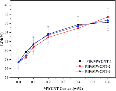
The variation trend of LOIs of PIF/MWCNT is shown in Fig. 9. The different diameters of MWCNTs have no obvious effect on the LOI value of the PIF/MWCNT. When MWCNT content increased from 0 wt% to 0.6 wt%, the LOI of PIF/MWCNT-1 increased from 27.4% to 36.2%. The LOI data for PIF/MWCNT were higher than 27%, indicating a high flame–retardant performance. The main chain of PIFs contains a benzene ring and an imide ring; thus, it has excellent flame–retardant properties.9,31,32 When PIFs are exposed to fire, the outer layer burns rapidly to form a protective layer of carbon, which inhibits gas shifts and produces volatile products in the thermal decomposition process, thus impeding oxygen circulation and heat conduction. At the same time, with increasing MWCNT content, the distribution of MWCNTs in the molecular chain of the composite is abundant. MWCNTs formed a continuous protective layer on the surface of the degraded carbon layer (PI) to protect the foam. The PIF/MWCNT materials show good heat insulation and improved flame–retardant performance. The foam composites also had good flame–retardant properties because of the interaction between nitrogen heterocycles of PIFs and MWCNTs. Therefore, the induction of MWCNTs can optimize the flame retardant performance of PIF.14,32–344 Conclusion
PIF/MWCNTS composites with different particle sizes (10–20 nm, 20–30 nm, > 50 nm) and different contents (0.05–0.6 wt%) of MWCNT were prepared via in situ polymerization. The mechanical properties of the composites first increased and then decreased with increasing MWCNTs contents. The compressive strength (0.107 MPa) and compression modulus (5.39 MPa) of PIF/MWCNT-1 reached a maximum value when the loading amount of MWCNT-1 was 0.2%. The degradation temperature of the PIF/MWCNT-1 nanocomposites was 321.5 °C, and the LOI was 36.2%. The effects of MWCNT diameter on the morphology and properties of PIF/MWCNTs were compared. Results show that a smaller diameter of MWCNTs leads to composites with better mechanical properties and thermal stability. Therefore, the addition of appropriate amounts of small-diameter MWCNTs (10–20 nm, 0.2 wt%) can significantly improve the performance of PIF/MWCNTs; different diameters of MWCNTs had no significant effect on the LOI values of PIF/MWCNTs. The LOI of PIF/MWCNT-1 reached 36.2% when the content of MWCNTs increased to 0.6 wt%. The LOI of the PIF/MWCNTS was higher than 27%, indicating that they had high flame retardancy.Conflicts of interest
There are no conflicts to declare.Acknowledgements
Manuscript data cannot be shared at the time of submission, and the raw/processed data required to reproduce the findings also cannot be shared due to technical or time constraints. This research was financed by the Department of Education of Liaoning Province (CN) (L2019001) under the project titled “Preparation and performance optimization of polyimide foam honeycomb composite with sound-absorbing and heat-insulating properties.” We thank LetPub (www.letpub.com) for linguistic assistance and pre-submission expert review.References
- J. W. Li, G. C. Zhang, Y. Yao, Z. X. Jing, L. S. Zhou and Z. L. Ma, RSC Adv., 2016, 6, 60094–60100 RSC.
- G. H. Sun, L. H. Liu, J. Wang, H. L. Wang, Z. Xie and S. H. Han, Polym. Degrad. Stab., 2014, 110, 1–12 CrossRef CAS.
- A. Xiang, L. Yan, L. W. Fu, Y. J. Chen, H. F. Tian and A.-V. Rajulu, Thermochim. Acta, 2017, 652, 160–165 CrossRef CAS.
- H. F. Tian, Y. Y. Yao, S. B. Ma, L. W. Fu, A. M. Xiang and A.-V. Rajulu, High Perform. Polym., 2018, 30(9), 1130–1138 CrossRef CAS.
- X. Chen, X. Sang and Q. Zhang, RSC Adv., 2015, 5, 53211–53219 RSC.
- J. Y. Yang, Y. S. Ye, X. P. Li, X. Z. Lü and R. J. Chen, Compos. Sci. Technol., 2018, 164, 187–194 CrossRef CAS.
- G. Sun, L. Liu, J. Wang, H. Wang, W. Wang and S. Han, Polym. Degrad. Stab., 2015, 115, 1–15 CrossRef CAS.
- H. F. Tian, Y. Y. Yao, S. B. Ma, J. L. Wu and A. M. Xiang, Adv. Polym. Technol., 2018, 37(7), 2470–2477 CrossRef CAS.
- J. W. Li, G. C. Zhang, J. T. Li, L. S. Zhou, Z. X. Jing and Z. L. Ma, Polym. Adv. Technol., 2017, 28(1), 28–34 CrossRef CAS.
- Z. X. Zhu, H. J. Yao, J. X. Dong, Z. Qian, W. Dong and D. H. Long, Carbon, 2019, 144, 24–31 CrossRef CAS.
- T. Huang, Y. Xin, T. Li, S. Nutt, C. Su, H. Chen, P. Liu and Z. Lai, ACS Appl. Mater. Inter., 2013, 5, 4878–4891 CrossRef CAS PubMed.
- R. M. Abdehgah, D. Ashouri and S. Mousavian, Des. Monomers Polym., 2013, 16(2), 108–115 CrossRef CAS.
- A. K. Barick and D. K. Tripathy, Mater. Sci. Eng., A, 2010, 527(3), 812–823 CrossRef.
- H. L. Yang, Z. Yu, P. Wu, H. W. Zou and P. B. Liu, Appl. Surf. Sci., 2018, 434(15), 318–325 CrossRef CAS.
- J. W. Li, Y. Q. Ding, N. Yu, Q. Gao, X. Fan, X. Wei, G. C. Zhang, Z. L. Ma and X. H. He, Carbon, 2020, 158, 45–54 CrossRef CAS.
- Y.-Y. Wang, Z.-H. Zhou, C.-G. Zhou, W.-J. Sun, J.-F. Gao, K. Dai, D.-X. Yan and Z.-M. Li, Appl. Mater. Inter., 2020, 12, 8704–8712 CrossRef CAS PubMed.
- J. F. Wang, X. X. Jin, H. Wu and S. Y. Guo, Carbon, 2017, 123, 502–513 CrossRef CAS.
- A. P. Ou, Z. Huang, R. Qin, X. C. Chen, Y. L. Li, Y. Liu, X. Y. Liu and X. Wang, Appl. Polym. Mater., 2019, 1, 2430–2440 CrossRef CAS.
- X. Zhao, B. Chen, G. D. Wei, J. M. Wu, W. Han and Y. Yang, Adv. Mater. Technol., 2019, 4(5), 1800723–1800731 CrossRef.
- L. Yan, L. W. Fu, Y. J. Chen, H. F. Tian, A. M. Xiang and A.-V. Rajulu, J. Appl. Polym. Sci., 2017, 134(20), 44828–44835 Search PubMed.
- L. Weng, T. Wang, P.-H. Ju and L.-Z. Li, J. Porous Mater., 2017, 24(2), 403–409 CrossRef CAS.
- Y. Song, H. Y. Yao, H. W. Tan, S. Y. Zhu, B. Dong, S. W. Guan and H. L. Liu, J. Polym. Sci., Polym. Chem., 2017, 55(14), 2281–2288 CrossRef CAS.
- X. Li, J. Wang, Y. B. Zhao and X. T. Zhang, ACS Appl. Mater. Inter ., 2018, 10(19), 16901–16910 CrossRef CAS PubMed.
- W. Fan, L. Z. Zuo, Y. F. Zhang, Y. Chen and T. X. Liu, Compos. Sci. Technol., 2018, 156, 186–191 CrossRef CAS.
- B. Zhang, P. Wu, H. W. Zou and P. B. Liu, High Perform. Polym., 2018, 30(3), 292–302 CrossRef CAS.
- S. Mallakpour and V. Behranvand, Colloid Polym. Sci., 2015, 293(1), 333–339 CrossRef CAS.
- X. Tian, S. Zhang, Y.-Q. Ma and Y.-L. Luo, Nanotechnology, 2020, 13, 195504–195511 CrossRef PubMed.
- S. C. Ryu, D. H. Kim, J. Kim, J. W. Lee and W. N. Kim, Polym. Com., 2017, 39, E1087–E1098 CrossRef.
- X. D. Wu, Y. Y. Han, X. X. Zhang, Z. H. Zhou and C. H. Lu, Adv. Funct. Mater., 2016, 26(34), 6246–6256 CrossRef CAS.
- Y. Kanbur and U. Tayfun, J Thermoplast Compos. Mater., 2018, 31, 1661–1675 CrossRef CAS.
- H. L. Yang, Z. L. Li, H. W. Zou and P. B. Liu, Polym. Adv. Technol., 2017, 28(2), 233–242 CrossRef CAS.
- J. Y. Oh, Y. S. Kim, Y. Jung, S. J. Yang and C. R. Park, ACS Nano, 2016, 10, 2184–2192 CrossRef CAS PubMed.
- M. H. Chen, J. H. Yin, R. Jin, L. Yao, B. Su and Q. Q. Lei, Thin Solid Films, 2015, 584, 232–237 CrossRef CAS.
- J.-Y. Kong, M.-C. Choi, G. Y. Kim, J. J. Park, M. Selvaraj, M. Han and C.-S. Ha, Eur. Polym. J., 2012, 48, 1394–1405 CrossRef CAS.
| This journal is © The Royal Society of Chemistry 2022 |

