DOI:
10.1039/D1RA04762K
(Paper)
RSC Adv., 2022,
12, 4656-4671
Investigation on structure, thermodynamic and multifunctional properties of Ni–Zn–Co ferrite for Gd3+ substitution †
Received
11th September 2021
, Accepted 24th December 2021
First published on 7th February 2022
Abstract
This study presents a modification of structure-dependent elastic, thermodynamic, magnetic, transport and magneto-dielectric properties of a Ni–Zn–Co ferrite tailored by Gd3+ substitution at the B-site replacing Fe3+ ions. The synthesized composition of Ni0.7Zn0.2Co0.1Fe2−xGdxO4 (0 ≤ x ≤ 0.12) crystallized with a single-phase cubic spinel structure that belongs to the Fd![[3 with combining macron]](https://www.rsc.org/images/entities/char_0033_0304.gif) m space group. The average particle size decreases due to Gd3+ substitution at Fe3+. Raman and IR spectroscopy studies illustrate phase purity, lattice dynamics with cation disorders and thermodynamic conditions inside the studied samples at room temperature (RT = 300 K). Ferromagnetic to paramagnetic phase transition was observed in all samples where Curie temperature (TC) decreases from 731 to 711 K for Gd3+ substitution in Ni–Zn–Co ferrite. In addition, Gd3+ substitution reinforces to decrease the A-B exchange interaction. Temperature-dependent DC electrical resistivity (ρDC) and temperature coefficient of resistance (TCR) have been surveyed with the variation of the grain size. The frequency-dependent dielectric properties and electric modulus at RT for all samples were observed from 20 Hz to 100 MHz and the conduction relaxation processes were found to spread over an extensive range of frequencies with the increase in the amount of Gd3+ in the Ni–Zn–Co ferrite. The RLC behavior separates the zone of frequencies ranging from resistive to capacitive regions in all the studied samples. Finally, the matching impedance (Z/η0) for all samples was evaluated over an extensive range of frequencies for the possible miniaturizing application.
m space group. The average particle size decreases due to Gd3+ substitution at Fe3+. Raman and IR spectroscopy studies illustrate phase purity, lattice dynamics with cation disorders and thermodynamic conditions inside the studied samples at room temperature (RT = 300 K). Ferromagnetic to paramagnetic phase transition was observed in all samples where Curie temperature (TC) decreases from 731 to 711 K for Gd3+ substitution in Ni–Zn–Co ferrite. In addition, Gd3+ substitution reinforces to decrease the A-B exchange interaction. Temperature-dependent DC electrical resistivity (ρDC) and temperature coefficient of resistance (TCR) have been surveyed with the variation of the grain size. The frequency-dependent dielectric properties and electric modulus at RT for all samples were observed from 20 Hz to 100 MHz and the conduction relaxation processes were found to spread over an extensive range of frequencies with the increase in the amount of Gd3+ in the Ni–Zn–Co ferrite. The RLC behavior separates the zone of frequencies ranging from resistive to capacitive regions in all the studied samples. Finally, the matching impedance (Z/η0) for all samples was evaluated over an extensive range of frequencies for the possible miniaturizing application.
1. Introduction
Ferromagnetic spinel ferrite materials have attracted great interest over the last several decades due to their multifunctional applications such as inductors, phase shifters, electromagnetic wave absorbers,1 optical materials,2 semiconductors,3 magnetic data storage,4 and magnetic resonance imaging (MRI) device.5 Especially, the high chemical and thermal stabilities with the low production cost of spinel ferrites make them a good candidate in the field of application.6 Therefore, the structural, magnetic and electric properties of spinels should be of great interest to research from both an elementary and functional point of view. In general, spinel ferrites are face-centered cubic (FCC) crystals formed with AB2O4 chemical formula, where A and B are the cations of divalent and trivalent metals, respectively. The cubic unit cell of spinel ferrite consists of 8 divalent metal ions (M2+), 16 trivalent iron ions (Fe3+) and 32 close-packed oxygen ions.7 Spinel structures are divided into two interstitial sites named the tetrahedral site (A-site) and octahedral site (B-site). In addition, spinel ferrite crystallizes to FCC structure containing 56 ions per unit cell or 8 formula units. Therefore, a large number of interstitial sites remain empty and only 8 tetrahedral and 16 octahedral sites are filled up by cations.7 The M2+ions prefer to be located in tetrahedral sites, while octahedral sites are occupied by Fe3+ ions. There is a possibility of cation migration in large empty interstitial sites.8 Moreover, partial inversion of ions in the spinel ferrite is also observed, which in terms of results is defined as cation redistribution between the A-site and B-site. Such an inversion has been reported as in nickel ferrite (NiFe2O4, NFO) nanowires, where a partial inversion of (Fe3+)A → (Fe3+)B and (Ni2+)B → (Ni2+)A was observed to result in magnetic hardening.9 However, the cation migration depends on various factors such as methods of synthesis, heat treatment, and/or doping into the A-site or B-site. Hence, physical activities like electric, magnetic and magneto-dielectric properties of any spinel ferrite are governed by its structural configuration. A large variety of methods including standard chemical reactions, sol–gel methods,10 hydrothermal/solvothermal methods,11 polyol,12 and co-precipitation.13 Have been developed by researchers to synthesize cubic spinel ferrites. Apart from these, a conventional solid-state reaction method14 is employed on a large scale because the starting materials are easy to access and not expensive. Ni–Zn ferrite is considered one of the pioneer ferromagnetic spinel ferrites due to its enormous application in the field of magnetic, electric and magneto-dielectric appliances.15 Moreover, Ni–Zn ferrites are well known due to their high resistivity and to reduce eddy current losses16 in applications. These ferrites have been extensively used in high-quality filters, radio frequency (RF) circuits and transformer cores.17,18 Typically, these ferrites have a mixed spinel structure with the cationic distribution of (Fex3+Zn1−x2+)[Nix2+Fe2−x3+]O4 (ref. 19 and 20) where x is the degree of inversion, while the parentheses () and [] represent the A-site (tetrahedral) and B-site (octahedral), respectively. In most of the cases, mixed spinels are detected as partial inverse spinels because the cation distribution varies frequently in-between normal and inverse spinels (0 < x < 1).21,22 In addition, Zn2+ cations show volatile nature to occupy both A and B sites.23–26 Fe3+ may exist in two oxidation states (Fe3+/Fe2+) in both A and B sites,27 which results in the electrical conduction in Ni–Zn ferrite. From an earlier report28 it is observed that the resistivity of Ni–Zn ferrite increases due to the addition of Co2+. Furthermore, Parvatheswara et al. reported that Co2+ substitution for Zn2+ enhances the saturation magnetization, while initial permeability decreases.29 Apart from this, nickel–zinc–cobalt (Ni–Zn–Co) ferrites became commercially useful materials for high-frequency applications in the radio frequency (RF) region.30 These ferrites have high resistivity, low eddy current loss, high permeability, high Curie temperature and high saturation magnetization.31–34 Furthermore, the electromagnetic properties of these spinel ferrites can be enhanced by ions substituting the trivalent ions with a controlled amount.35 Stergiou has reported that dielectric orientation polarization is enhanced in La and Y doped Ni–Zn–Co spinel ferrites.31 Rare-earth (RE) ions due to their unpaired 4f electrons, could be a role of originating magnetic anisotropy because of their orbital shape. As the magneto-crystalline anisotropy in ferrite is related to the 4f–3d coupling between the transition metal and rare earth ions, Gd3+ ions into spinel Ni–Zn–Co ferrite is expected to improve their electromagnetic properties.36 Apart from this, RE elements have a larger ionic radius than Fe and therefore, a slight amount of doping/substitution at the B site of any spinel ferrite can modify their physical properties extensively. Moreover, the electrical resistivity of Ni–Zn–Co ferrites is expected to increase due to Gd substitution as the improvement of electrical resistivity with RE substitution in ferrites has been reported.37–39 However, the synthesis of Gd doped Ni–Zn–Co ferrites is a challenging task because of the co-existence of undesired phases such as Fe2O3 along with the spinel. In addition, the substitution of RE ions into the spinel structure has been reported to lead to structural distortion and to induce strains and to significantly modify the electrical and magnetic properties.40,41
In the present study, the main objective is to synthesize a Ni–Zn–Co spinel ferrite cost-effective and to enhance the physical properties of the product by Gd3+ substitution at Fe3+ located in the B-site. This investigation aims to evaluate the modification of structural, electrical and magnetic properties due to the substitution of Gd3+ in Ni–Zn–Co ferrite on a large scale. Our expectation is focused on the positive modification of the physical properties of the synthesized samples and to ensure that the synthesized materials will not only be restricted to the study only but also be an ideal material for broad applications in the future.
2. Experimental
2.1. Sample synthesis
The standard solid-state reaction method, including the double sintering technique42 was applied to synthesize the Gd3+ substituted Ni–Zn–Co ferrite of composition Ni0.7Zn0.2Co0.1Fe2−xGdxO4 (where, x = 0.00, 0.02, 0.05, 0.07, 0.10 and 0.12). The raw materials of analytical-grade Fe2O3, Gd2O3, NiO, CoO and ZnO obtained from Inframat Advanced Materials, USA were used. The stoichiometric amounts of these materials were carefully weighed and thoroughly mixed by hand milling for 6 h in an agate mortar. An amount of 2% polyvinyl alcohol (PVA) was mixed with the milled powder. The mixture was then pressed into a pellet-shaped disk kept in stainless steel die under a pressure of 10 kN m−2 applied by a hydraulic press. Thereafter, each green sample was pre-sintered at the temperature of 850 °C for 5 h followed by furnace cooling. The whole process was repeated for all compositions of samples. Again disk-shaped samples were ground thoroughly for 4 h with the addition of acetone. The mixture was then dried up in the air and a small amount of PVA (5%) was added with it. Again the pellet-shaped sample disks were prepared following the same procedure as discussed. Finally, the prepared sample disks were sintered at 1200 °C for 3 h followed by furnace cooling naturally.
2.2. Characterization
For structural investigations, XRD patterns were recorded for the synthesized compositions Ni0.7Zn0.2Co0.1Fe2−xGdxO4 (0 ≤ x ≤ 0.12) using a Philips X'pert PRO X-ray diffractometer (PW3040) using Cu-Kα radiation (λ = 1.5405 Å) and the scanning range was 20° ≤ 2θ ≤ 70°. The microstructures were observed using a Tecnai G2 30ST model transmission electron microscope (TEM). Raman spectra were obtained in the range from 200 to 1200 cm−1 using a Raman spectrometer of the model: Mono Vista CRS + S & I, Germany. Fourier-transform infrared spectroscopy (FTIR) analysis was performed on all samples using a Thermo Nicolet NEXUS 470 FTIR spectrometer in the range of 400–1600 cm−1, wavenumbers. The disk-shaped samples were polished using a metallurgical polishing machine to reduce the surface roughness. Then, both sides of the pellet were coated with silver paste and two different connections were made from both the outer-coated surface of the sample disks. The dielectric constant and permeability were measured for all samples using an impedance analyzer of the Wayne Kerr 6500B series. Temperature-dependent resistivity of the pellet samples was measured using the same impedance analyzer and Keithley electrometer model no. 6514, placing the sample inside a woven arranged with a temperature controller.
3. Results and discussion
The XRD patterns of the synthesized compositions Ni0.7Zn0.2Co0.1Fe2−xGdxO4 (0 ≤ x ≤ 0.12) calcined at 1200 °C for 3 h are shown in Fig. 1(a). The XRD patterns of all samples belonged to a single cubic spinel structure of the Fdm space group, which was confirmed from the presence of (220), (311), (222), (400), (422), (511) and (440) planes as observed in JCPDS #08-0234.43 Rietveld refinement44,45 of the XRD data was performed to obtain the structural parameters such as the lattice constant (a) and unit cell volume (V) using a Fullprof suite program (2.05) and the obtained values are shown in Table 1. All the samples showed the goodness of fit values (χ2) ranging from 1.81 to 2.11 (Table 1). The crystallite size (d) and lattice strain (ε) of the studied samples were obtained from a sharp and separate diffraction peaks at the (311) plane and the formulae involved in this estimation have been included in the supplementary part. It can be seen in Fig. 1(b) that both crystallite size (d) and lattice constant (a) are increasing even for a slight amount of Gd3+ substation in the place of Fe3+, which is attributed to the larger ionic radii of Gd3+ (0.938 Å) compared to that of Fe3+ (0.645 Å) ions at octahedral Fe3+ ions.40 However, more amount of Gd3+ substitution could not affect longer radii except slight drops in both a and d. In addition, the hopping lengths (distance between magnetic ions) in the tetrahedral site (HT) and octahedral site (HO) were determined according to the relations  46 The values of HT and HO are illustrated in Fig. 1(c) and found to be concomitant with a and d.
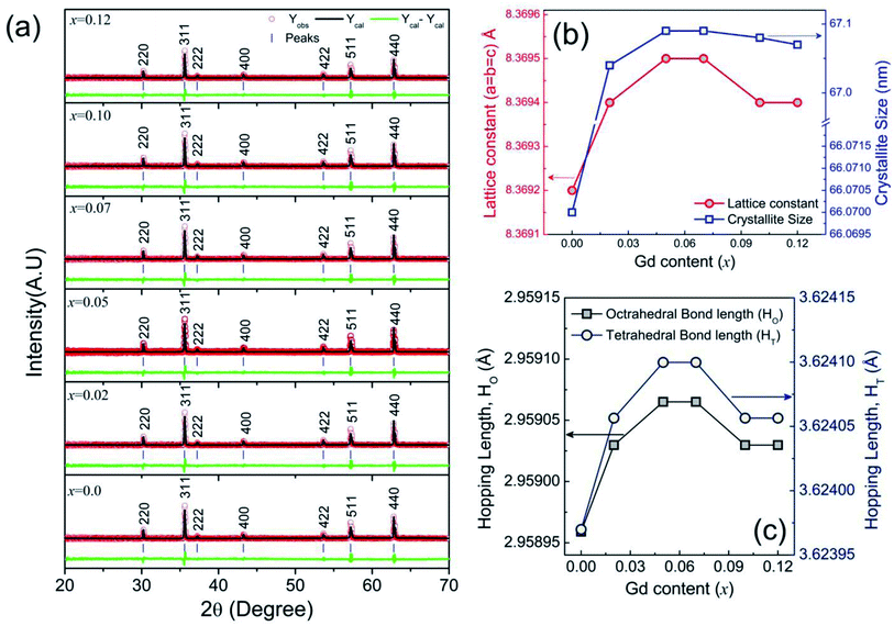 |
| | Fig. 1 Structural analysis for Ni0.7Zn0.2Co0.1Fe2−xGdxO4 (0 ≤ x ≤ 0.12) using (a) Rietveld refinement of X-ray diffraction patterns (b) variations of lattice constants and crystallite size with the Gd content substitution and (c) variations of Hopping lengths with Gd content (x). | |
Table 1 Structural parameters obtained from Rietveld refinement of XRD data recorded for Ni0.7Zn0.2Co0.1Fe2−xGdxO4 (0 ≤ x ≤ 0.12) ferrites where the best fit depends on χ2 (Goodness of fit), Rp (residuals for the unweighed pattern) and Rwp (residuals for the weighed pattern)
| Parameters |
x = 0.00 |
x = 0.02 |
x = 0.05 |
x = 0.07 |
x = 0.10 |
x = 0.12 |
| Space group |
Fdm |
|
|
|
|
|
| Crystallite size (nm) |
66.07 |
67.04 |
67.09 |
67.09 |
67.08 |
67.07 |
| Lattice strain |
0.0018 |
0.0018 |
0.0017 |
0.0018 |
0.0018 |
0.0018 |
| a = b = c (Å) |
8.3692 (2) |
8.3694 (1) |
8.3695 (1) |
8.3695 (1) |
8.3694 (2) |
8.3694 (2) |
| V (Å3) |
586.2 (2) |
586.3 (2) |
586.3 (2) |
586.3 (2) |
586.3 (2) |
586.3 (2) |
| χ2 |
1.87 |
1.89 |
1.93 |
2.11 |
1.88 |
1.81 |
| Rp |
7.1 |
8.0 |
8.5 |
9.0 |
8.1 |
7.7 |
| Rwp |
4.9 |
5.8 |
6.8 |
6.5 |
6.0 |
5.9 |
3.1. Morphological analysis
The grain nucleation and crystal growth of the derived nano-crystals were analyzed by TEM (TALOS F200X). Fig. 2 shows the surface morphology and diffraction rings of selected area electron diffraction (SAED) patterns for Ni0.7Zn0.2Co0.1Fe2−xGdxO4 (0 ≤ x ≤ 0.12) samples. It is observed that the diffraction rings corresponding to (111), (220), (311), (222), (400), (422), (511) and (440) planes for all the studied samples and the planes are consistent with those observed in XRD data. Therefore, the structure is well-matching with the spinel structure. However, the ring designated in the SAED mode indicates the polycrystalline nature of the sample. The average particle sizes (XA) were estimated using ImageJ 1.50i software and Lorentz distribution function and are shown as the inset of Fig. 2(a–f). From the micrographs, it can be observed that the particles are almost spherical and the histogram shows the distribution size of nanoparticles ranging from 20 to 120 nm. However, XA was found to be around 81.7 nm for pure Ni–Zn–Co ferrite and decreases to 42.9 nm for Gd3+ substitution in Ni–Zn–Co ferrite. These may be attributed to the fact that Gd has a higher thermal stability than other elements in the composition and the ionic radius is larger than any other transition element. The sintering temperature of Ni–Zn–Co ferrite was 1200 °C while the melting point of Gd is 2420 °C. Therefore, increasing the content of Gd in the composition is expected to enhance the thermal stability of the composite as a whole restricting the grain growth of the composite matrix.
 |
| | Fig. 2 (a–f) TEM micrographs obtained for Ni0.7Zn0.2Co0.1Fe2−xGdxO4 (0 ≤ x ≤ 0.12) nanoparticles along with selected area electron diffraction (SAED) pattern and the diffraction rings well-matched with the spinel structure. | |
3.2. Raman analysis
The lattice dynamics with cation disorders were investigated using Raman spectroscopy on Ni0.7Zn0.2Co0.1Fe2−xGdxO4 (0 ≤ x ≤ 0.12) samples at room temperature, RT = 300 K and the measurement range was 200 to 1600 cm−1. The spectra illustrated in Fig. 3(a) confirm five primary Raman scattering bands in all studied samples and the bands are corresponding to three F2g modes (220–227 cm−1, 460–497 cm−1, and 570–595 cm−1), one A1g mode (708–805 cm−1) and one Eg mode (315–340 cm−1). In pure Ni–Zn–Co ferrite (x = 0.00), a shoulder-like feature of the Raman band at 709 cm−1 was observed at 667 cm−1, which is nearly similar to the reported band feature for Fe3O4 in the range of 650–750 cm−1. These adjacent bands are defined as A1g(1) and A1g(2) modes, which reflect the stretching vibration of Fe3+ and O2− ions in the tetrahedral site and these bands are shifted to the higher side for Gd3+ substitution in the pure Ni–Zn–Co ferrite sample. The absence of any sharper and well-defined Raman bands at the lower wavenumber rules out the existence of the Fe3O4 phase in most of the Gd-doped Ni–Zn–Co ferrite samples. However, the higher frequency mode observed at 1170 cm−1 in pure Ni–Zn–Co ferrite and also at 1112 cm−1 for x = 0.10 samples indicate the presence of the γ-Fe2O3 phase as confirmed in an earlier report.47 Therefore, Raman spectroscopy could be a sensitive way to obtain information on this type of extra phase whereas XRD was unable to predict the phase. In addition, the shifting of the A1g peaks with a clear decrease in intensity of γ-Fe2O3 peak is specified by the degree of inversion of the spinel due to Gd3+ substitution in the studied ferrite.48 The redistribution of cations and cation disorder due to Gd3+ substitution have been analyzed quantitatively from the effective force constants of the ions existing in the tetrahedral (FT) and octahedral (FO) positions. The estimation process of FT and FO have been discussed in the supplementary part. It is observed that FO and FT have inverse relationship as shown in Fig. 3(b) and large variation in FO indicates that the octahedral site is dominated by Gd3+ substitution. However, FT and FO are also inversely proportional to the bond length (viz., Co–O, Ni–O, Fe–O, Zn–O, and Gd–O).
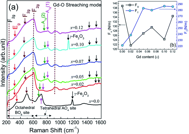 |
| | Fig. 3 (a) Raman spectra of Ni0.7Zn0.2Co0.1Fe2−xGdxO4 (0 ≤ x ≤ 0.12) scanned from 200 cm−1 to 1600 cm−1 (b) the effective force constants of tetrahedral (FT) and octahedral (FO) positions sites estimated from Raman spectra. | |
3.3. Elastic properties and thermal behavior
FTIR is a powerful tool that can estimate the elastic properties and the thermodynamic condition in ferrites. Therefore, FTIR spectra were recorded at RT with the variation of wavenumber from 350–1600 cm−1, and a single spinel cubic structure was confirmed in all of the studied samples. IR spectra for all studied samples are shown in Fig. 4(a). Here, two prominent absorption peaks are observed at 580 cm−1 and 370 cm−1 which are denoted as νA and νB, respectively. Generally, the absorption band at 580 cm−1 is assigned to the motion of oxygen in the tetrahedral site (A-site), whereas the mode at 370 cm−1 corresponds to the octahedral site (B-site) for spinel ferrites.49 The absorption band at 1085 cm−1 indicates the C–N vibration. Moreover, the band at 1399 cm−1 is due to the presence of trapped nitrates.50 The absorption peak νA continues to be broad upon increasing the substitution of Gd3+ at Fe3+ ions. The reason is that the distance between Fe–O bonds at the octahedral site is highly affected when Gd3+ with its larger ionic radius and atomic weight sits at the place of Fe3+.51 Furthermore, the absence of any shoulder at νB confirms the presence of Fe2+ striking out of the octahedral site consequently. The slight shift of absorption bands at νA and νB to the lower side indicates the perturbation in the Fe2+–O2− bond that occurred for Gd3+ substitution.52 The force constants of Fe–O at the octahedral site (kFe–OO) and tetrahedral site (kFe–OT) are calculated from the wavenumber (![[small nu, Greek, macron]](https://www.rsc.org/images/entities/i_char_e0ce.gif) ) from relation53
) from relation53| |
 | (1) |
where c is the velocity of light, k is force constant and the effective mass (μ) of Fe–O bond that has been calculated by μ = (MO × MFe)/(MO + MFe) where, MO and MFe are the atomic weight of O and Fe, respectively. Therefore, the average bond length (r) between Fe and O was calculated using the formula:  for both octahedral and tetrahedral sites. Fig. 4(b) and (c) show the variation of the force constant of the Fe–O bond and its bond length, respectively, due to Gd3+ substitution in place of Fe3+. It is observed that both kFe–OO and kFe–OT are maximum for the sample x = 0.07, wherein, the Fe–O bond length is minimum. Again, the overall force constants of ions at the octahedral site (kO) and tetrahedral site (kT) are expressed as54,55
| |
 | (2) |
| |
 | (3) |
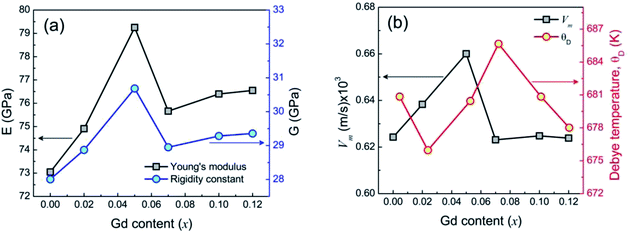
where, νA and νB are the IR band frequencies at the A site and B site, respectively. Moreover, MT and MO are the molecular weights of ions at tetrahedral and octahedral sites respectively. Therefore, the average bond length of cation–anion at the octahedral and tetrahedral site using the same formula  In a recent study on Ni–Zn–Al ferrite, Jalel Massoudi et al.54 reported that kT was found to decrease while kO increases. In our present system, this trend is followed by the samples 0.07 ≤ x ≤ 0.12 while the force constants for both tetrahedral and octahedral sites increase for the sample 0.00 ≤ x ≤ 0.07 shown in Fig. 4(d). In addition, the binding force between atoms of the spinel lattice of the studied samples due to Gd3+ substitution was evaluated from the variation of Young's modulus (E), rigidity modulus (G) and Poisson's ratio (σ), as discussed in an earlier report of Wooster's work.56 Here, the elastic constants have been estimated from the average force constant (kav) as discussed in the supplementary part. The Poisson's ratios (σ), as depicted in Table 2 are observed to diverge from 0.29 to 0.31 depending on the compositions and the values lie in the range from −1 to 0.5, which is consistent with the theory of isotropic elasticity. However, the Zener anisotropy factor,57 A as shown in Table 2 yields deviations less than unity signifying the degree of anisotropy. Moreover, the obtained values of stiffness (C12) are positively ranging from 81.59 GPa to 86.55 GPa depending on the compositions and indicating the stability of the synthesized Gd-doped Ni–Zn–Co ferrite. Fig. 5(a) shows the variation of E and G due to Gd3+ substitution in Ni–Zn–Co ferrite, which is found to be increasing sharply with increasing Gd amount up to x = 0.05 and then drops to a lower value for x = 0.07. However, more amount of Gd3+ substitution (0.07 ≤ x ≤ 0.12) could not improve E and G remarkably, except a slight increase of x = 0.07. The overall variations of elastic moduli change concomitantly with the bond lengths between ions as shown in Fig. 4(c) and (e) and it is confirmed that the interatomic bonding between cations is getting strengthened up to x = 0.05 and above x = 0.07.
 |
| | Fig. 4 (a) IR spectroscopy for Ni0.7Zn0.2Co0.1Fe2−xGdxO4 (0 ≤ x ≤ 0.12) samples scanned from 350 cm−1 to 1600 cm−1. (b) Forces constants of Fe–O at the octahedral site (kFe–OO) and tetrahedral site (kFe–OT), (c) Fe–O bond length octahedral site (LFe–OO) and tetrahedral site (LFe–OT) (d) overall force constant of ions at the octahedral site (KO) and tetrahedral site (KT) (e) cation–anion bond length at the octahedral site (LO) and tetrahedral site (LT). | |
Table 2 Shifting of Raman peaks (Δω) with grain size, (XA), Poisson's ratio (σ), anisotropy factor (A), Debye temperature (θD), Curie temperature (TC) and exchange interaction (J) obtained for Ni0.7Zn0.2Co0.1Fe2−xGdxO4 (0 ≤ x ≤ 0.12)
| Gd content (x) |
Δω |
XA (nm) |
σ |
A (GPa) |
TC (K) |
J (J) × 10−14 |
θD (K) |
| 0.00 |
0.00 |
81.7 ± 1 |
0.30 |
0.53 |
731 |
2.52 |
685.67 |
| 0.02 |
27.12 |
56.1 ± 3.8 |
0.30 |
0.54 |
718 |
2.48 |
680.85 |
| 0.05 |
92.99 |
55.3 ± 1.9 |
0.29 |
0.55 |
715 |
2.47 |
680.85 |
| 0.07 |
93 |
50.9 ± 2.8 |
0.31 |
0.53 |
713 |
2.46 |
680.45 |
| 0.10 |
97.99 |
42.9 ± 0.9 |
0.30 |
0.53 |
712 |
2.45 |
678.01 |
| 0.12 |
96.86 |
45.0 ± 0.03 |
0.30 |
0.53 |
711 |
2.45 |
675.97 |
 |
| | Fig. 5 (a) Deviation of Young's modulus (E) and rigidity modulus (G) due to Gd3+ substitution in Ni–Zn–Co ferrite and (b) variation of the mean elastic wave velocity (Vm) and Debye temperature (θD) due to Gd3+ substitution for in Ni–Zn–Co spinel ferrite. | |
Apart from this, Debye temperature (θD) is characteristic of a particular material that can explain the thermal behavior of solids as dominated by homogeneous isotropic massless phonons and θD is a temperature at which phonons can have the maximum frequency. The values of θD in all studied samples were obtained from the following relation58
| |
 | (4) |
where ℏ is the Planck's constant,
KB is the Boltzmann's constant,
c is the velocity of light, and
νav is the average value of wavenumbers. It was found that
θD increases with the increase in Gd
3+ substitution.
Fig. 5(b) shows the variation of
θD and mean elastic wave velocity (
Vm) due to Gd
3+ substitution. It is well shown in
Fig. 5(b) that (
θD) increases initially in the range of 0.02 ≤
x ≤ 0.05 and decreases with higher substitution of Gd
3+ ions. The increase in
θD due to Gd
3+ substitution indicates that the lattice vibrations are holding up for Gd
3+substitution. According to the specific heat theory,
59 the increase of
θD may be attributed to the decrease of the conduction electron density
Nn (n-type), and therefore the density of conduction holes
Np (p-type) increases. Moreover, according to Anderson's formula,
60 θD should increase linearly with
Vm. However, ferrite materials are mostly porous and anomalies are observed.
3.4. Temperature-dependent magnetic properties
The magnetic properties of the studied samples were evaluated from magnetic permeability (μ) as well as thermo-magnetization under the application of a 1 kOe-applied field. Fig. 6(a) shows the real part of the magnetic permeability, μ′ for Ni0.7Zn0.2Co0.1Fe2−xGdxO4 (0 ≤ x ≤ 0.12) samples measured with the variation of temperature ranging from 300 to 850 K. It is manifested that μ′ in all studied samples falls to a lower value at a certain temperature, depending on the sample compositions and the cut-off temperature (Tx) is obtained from the slope change in μ′ as depicted in the inset of Fig. 6(a). Interestingly, the values of Tx are found to decrease initially for the low amount of Gd3+ substitution (0.00 ≤ x ≤ 0.05) while they rise in Gd3+ substitutions above x = 0.05.
 |
| | Fig. 6 (a) Temperature-dependent real permeability (μ′) for Ni0.7Zn0.2Co0.1Fe2−xGdxO4 (0 ≤ x ≤ 0.12) (b) thermo-magnetization under 1 kOe magnetic field with (b) First order derivative of magnetization  with the variation of temperature. with the variation of temperature. | |
The values of μ′ at RT for other samples are also attributed to the interplay between grain size and porosities of the synthesized samples. In an illustrative way, μ′ is originated from the susceptibilities due to spin rotation (χspin) and domain wall motion, (χdw) as estimated by μ′ = 1 + χspin + χdw61 where χspin = 2πMs2/K and χdw = 3πMs2DSEM/4γ. Hence, a decrease in μ′ is an indication of weak domain wall mobilization, which is confined at intra-granular pores and grain sizes. Moreover, Gd3+ substitution is responsible for creating a large anisotropic constant for which μ′ decreases.62 Apart from this, the thermo-magnetization between 300 K to 850 K under the application of a constant field of 1 kOe confirms the ferromagnetic (FM) to paramagnetic (PM) transition in all studied samples as illustrated in Fig. 6(b). Therefore, the Curie temperature (TC) of the derived spinel ferrite was obtained from the first-order derivative of thermo-magnetization (dM /dT) as illustrated in the supplementary part. It is manifested that the FM to PM phase transition becomes markedly sharper for more Gd3+ substitution, particularly for 0.07 ≤ x ≤ 0.12. Moreover, the value of TC decreases from 731 to 711 K as the grain size decreases from 81.7 nm to 42.9 nm. Here in the Ni–Zn–Co ferrite sample, the replacement of Fe3+ ions by Gd3+ ions may reduce active magnetic connections for magnetic ion per formula unit resulting in a decrease of TC.63–65 In addition, the exchange interaction J for A–B sublattice is proportional to TC, which can be expressed by66
| |
 | (5) |
where,
KB is the Boltzmann constant,
z = 8 and
s = 1/2. Therefore,
J is directly proportional to
TC in thermo-magnetization and shown in
Fig. 7. The ionic radius of Gd is much higher than that of other transition metals. Therefore, the substitution of Gd into the NI–Zn–Co ferrite lattice is expected to expand the lattice, resulting in a small rise of lattice parameter and this has been reflected in the result of the lattice parameter as shown in
Table 1. A slight increase in the lattice parameter was observed with the increase of Gd. The Curie temperature was found to decrease from 731 K to 711 K with the substitution of Gd up to
x = 0.12 and the decrease of
TC is well explained with the increase in the lattice parameter, which reduces the strength of the exchange constant (
J).
TC is directly proportional to
J. So the results are compatible with the theory of exchange interaction.
 |
| | Fig. 7 The variation Curie temperature (TC) and exchange interaction (J) due to Gd3+ substitution in Ni–Zn–Co ferrite. | |
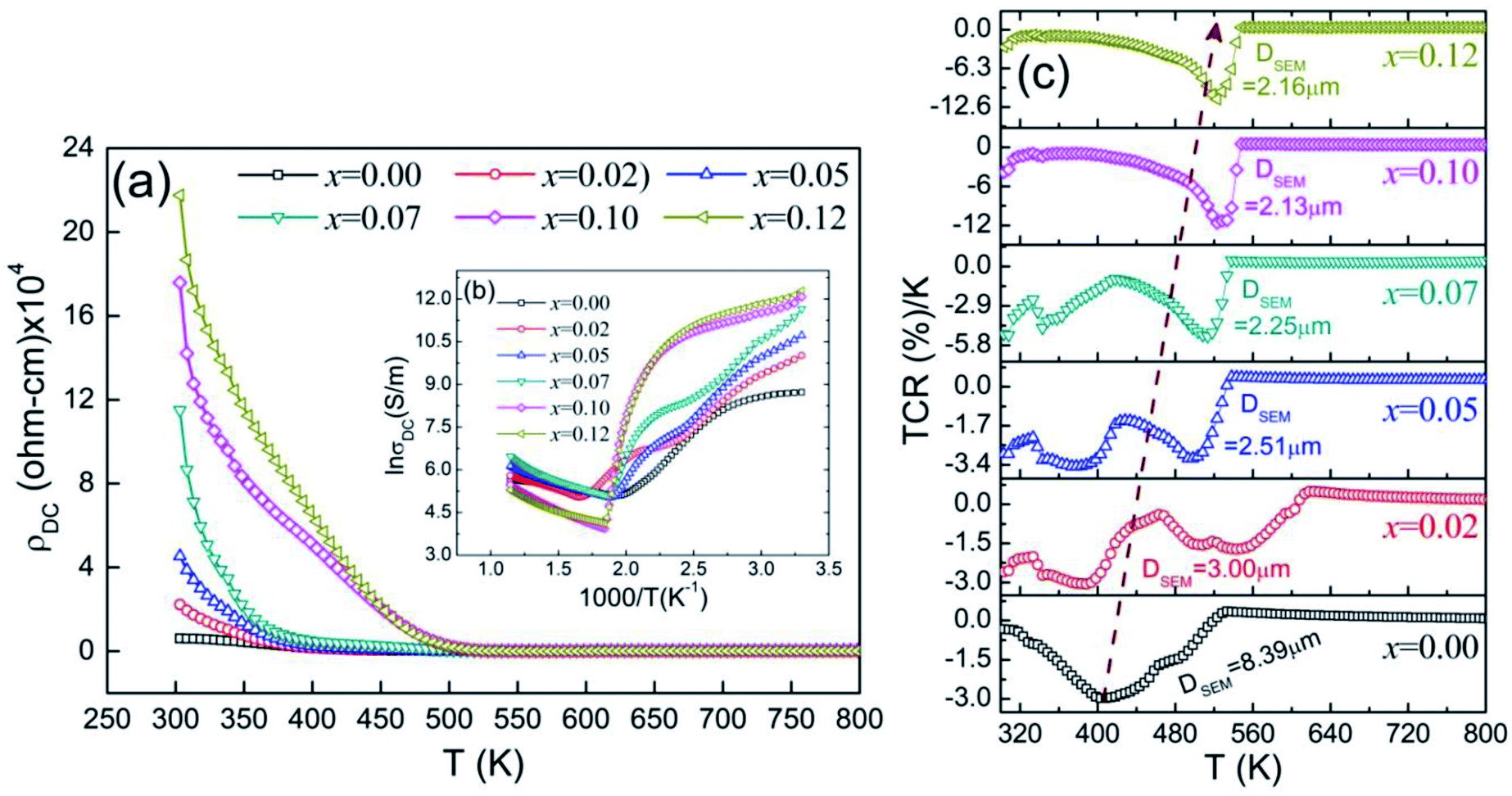
3.5. Transport properties
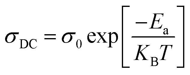
Direct-current (DC) resistivity (ρDC) measurement is one of the powerful techniques to explain the electrical behavior of ferrite samples. The temperature dependence ρDC was measured for Ni0.7Zn0.2Co0.1Fe2−xGdxO4 (0 ≤ x ≤ 0.12) in the range of 300–800 K and shown in Fig. 8(a). Here, a continuous decrease in ρDC with increasing temperature was observed for all samples, which reflects the semiconducting nature of the studied samples. The reason is that activated drift mobility of electric charge carriers increases with the rise of temperature. Moreover, the values of ρDC at RT increase from 6.2 × 10³ Ω cm to 2.2 × 10⁵ Ω cm for increasing Gd3+ amount in the parent Ni–Zn–Co ferrite. According to Verwey's hopping mechanism,67 the electronic conduction in ferrites is dominated by the hopping of electrons between the same ions with different valence states (such as Fe3+ and Fe2+ ions), which is spread arbitrarily over lattice sites.68 In addition to this, samples with higher ρDC lead to very low eddy current losses and therefore the sample for x = 0.12 would be suitable for electronic inductors, electromagnets, transformers, electronic inductors, and at high-frequency applications,69 while the undoped Ni–Zn–Co ferrite sample with higher conductivity may be suitable to be used in solid oxide fuel cells.70 The activation energy (Ea) was calculated using the well-known Arrhenius equation that describes the relationship between conductivity (σDC) and temperature (T) as:| |
 | (6) |
where σ0 is a pre-factor that defines the conductivity when the reciprocal temperature approaches zero. Therefore, Ea was calculated from the linear fit of the plots between ln(σDC) and 1000/T as shown in Fig. 8 (inset figure). It is observed from Fig. 8(b) that there is a slope change or break at a certain temperature for all derived samples that divide the curve into two regions and the temperature is denoted as the electronic transition temperature (TEC). However, the plots for x = 0.10 and 0.12 samples show three zones, i.e., two breaks. The second break may have originated due to the variations in the conduction mechanism influenced by the magnetic order.71 The calculated activation energies are denoted as E1 and E2 as shown in Fig. 9 and the corresponding regions are identified as Tr1 and Tr2, respectively and Tr1 < Tr2. For the lower amount of Gd3+ substitution, (0.0 ≤ x ≤ 0.07) E2 is lower than E1. Conversely, in the samples with higher Gd3+ substitution (0.10 ≤ x ≤ 0.12) E2 is higher than E1. At the Tr1 region, the conduction mechanism is dominated by the hopping of electrons between Fe2+ ↔ Fe3+ pairs,72 while at the region Tr2, the mechanism may be expected from Ni2+ + Fe3+ ↔ Fe2+ + Ni3+.73 The value of the temperature coefficient of resistance (TCR) in studied samples can be calculated from temperature (T) dependent resistivity (ρDC) following the relation given as54| |
 | (7) |
 |
| | Fig. 8 (a) Temperature-dependent DC resistivity (ρDC) for Ni0.7Zn0.2Co0.1Fe2−xGdxO4 (0 ≤ x ≤ 0.12) samples and (b) The inset showing lnσDC vs. 1000/T plot and (c) variations of TCR with temperature for Gd3+ substitution in Ni–Zn–Co ferrite. | |
 |
| | Fig. 9 Linear fitting of Arrhenius plot in between lnσDC and 1000/T for Ni0.7Zn0.2Co0.1Fe2−xGdxO4 at two temperature regions where (a) x = 0.00, (b) x = 0.02, (c) x = 0.05, (d) x = 0.07, (e) x = 0.10 and (f) x = 0.12. | |
Fig. 8(c) shows the TCR values for all studied samples in between 300 to 800 K. For the temperature dependency of TCR, all samples show a peak and the peak position increase with increasing Gd3+ substitution. The shifting of peak position is also dominated by the grain size where it increases for lowering the size of the grains. The peak position (TTCR) and TCR values at the peak are given in Table 3. It is observed that the peak TCR values are enhanced from −2.9% K−1 at 406 K to −12% K−1 at 522 K as for 0.00 ≤ x ≤ 0.12 and it is maximum for sample x = 0.10 and 0.12. All the TCR data are shown in Table 3. The sintering temperature and time play a key role in the variation of peak TCR value.54 However, here, all samples were sintered at 1200 °C for 3 h. Hence, Gd3+ substitution is the major factor for the variation and is enhanced for Gd3+ substitution. As compared to the TCR values from the earlier report on Ni–Zn–Al ferrite.74 These results suggest that Gd3+substituted Ni–Zn–Co ferrite could be suitable for applications in the bolometric device.
Table 3 Data obtained from temperature-dependent DC resistivity showing electronic transport temperature (TEC), activation energy on both sides of electronic transition (E1 and E2), temperature coefficient of resistance (TCR) and its peak temperature (TTCR)
| Gd content (x) |
TTCR (K) |
TCR (%)/K |
TEC (K) |
E1 (eV) |
E2 (eV) |
| 0.00 |
406 |
2.29 |
344 |
0.70 |
0.69 |
| 0.02 |
544 |
1.8 |
417 |
3.20 |
1.44 |
| 0.05 |
498 |
3.2 |
406 |
3.95 |
1.52 |
| 0.07 |
510 |
5.4 |
400 |
3.53 |
1.91 |
| 0.10 |
522 |
12 |
425 |
1.42 |
2.21 |
| 0.12 |
523 |
11.7 |
424 |
1.46 |
1.70 |
3.6. Electronic contribution
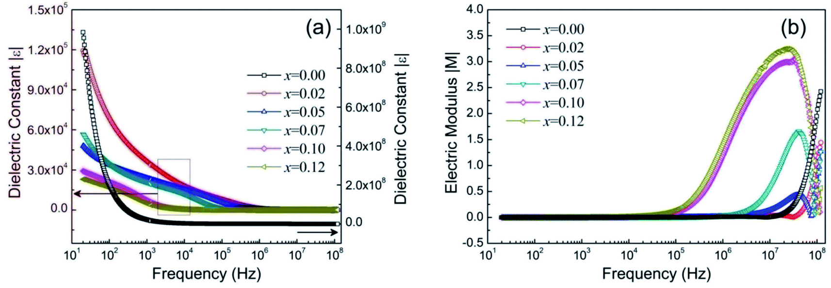
The study of dielectric properties was conducted to measure the electric polarizability of Ni0.7Zn0.2Co0.1Fe2−xGdxO4 (0 ≤ x ≤ 0.12) samples by which its electronic contribution can be estimated. In general, materials with high permittivity (ε) polarize more in response to an applied electric field, while materials with low dielectric constant (ε) can store more energy inside. Therefore, the absolute permittivity |ε| was observed with the variation of frequency from 20 Hz to 100 MHz, as shown in Fig. 10(a). The relatively high values of |ε| at low-frequency (<1 kHz) indicate the existence of charge defects due to oxygen vacancies. As seen from Fig. 10(a), |ε| decreases with increasing frequency. On the other hand, the absolute value of the electric modulus |M| describes the relaxation phenomena during the electronic response in any ferrite material. Fig. 10(b) shows room temperature |M| in the derived samples for the frequency ranging from 20 Hz to 100 MHz. It is observed that |M| increases with increasing frequency above a certain frequency, which arises due to the variation of dielectric permittivities at different frequencies. Usually, the variation in |ε| as well as |M| at lower frequency is attributed to the electronic polarization originating from the electronic exchange between Fe2+ and Fe3+ ions known as n-type charge carriers at the octahedral site.75 However, in the studied samples (Ni0.7Zn0.2Co0.1Fe2−xGdxO4 with 0 ≤ x ≤ 0.12) Ni3+/Ni2+ ions are also present and it may yield p-type charge carriers at the B site. Hence, p-type charge carriers also contribute to the net polarization. The mobility of p-type charge carriers is very low compared to that of n-type carriers. Therefore, the net polarization decreases with increasing frequency resulting in a decrease in |ε| even at low frequency. A slow variation of |ε| in the frequency range of 1 to 100 kHz is observed for the Gd3+ doped samples, which suggests that ionic and electronic polarizations become frequency independent in this range due to Gd3+ substitution. However, |ε| is almost the same in the high-frequency region (>1 MHz). On the other hand, at low frequency (<102 Hz), the values of |M| are observed to be very low (∼0). At high frequency (>10 MHz), dispersion in |M| is observed due to conductivity relaxation. The relaxation processes are spread over an extensive range of frequencies for increasing the substitution of Fe3+ by Gd3+. Moreover, a single relaxation process is confirmed in all studied samples from the modulus plane plot (imaginary M′′ versus real M′) shown in Fig. 11. Here the smaller semicircle arcs are observed for 0 ≤ x ≤ 0.07, which correspond to the weak grain boundary effects rather than the dominant grain effects76 while arcs become larger for more Gd3+ substitution (0.10 ≤ x ≤ 0.12). Hence, the bulk or grain response is dominant in samples for x = 0.10 and 0.12.
 |
| | Fig. 10 Frequency-dependent dielectric properties of Ni0.7Zn0.2Co0.1Fe2−xGdxO4 (0 ≤ x ≤ 0.12) where (a) absolute value of dielectric constant (|ε|) and (b) absolute electric modulus (|M|) estimated in the range of 20 Hz to 100 MHz at room temperature. | |
 |
| | Fig. 11 Complex modulus plane plots for Ni0.7Zn0.2Co0.1Fe2−xGdxO4 (0 ≤ x ≤ 0.12) ferrites. | |
3.7. Impedance analyses
The impedance analysis was performed at RT to study the RLC behavior of the studied spinel ferrites in the range of 20 Hz to 100 MHz. This technique provides information about resistive (real part, Z′) and reactive (imaginary part, Z′′) contributions in any ferrite materials. Generally, the total impedance acts as pure resistance at lower frequencies and pure capacitance at higher frequencies. Fig. 12(a) shows the frequency-dependent absolute value of impedance (|Z|). It is observed that |Z| decreases as the frequency is increased and reaches the lowest constant value for 0 ≤ x ≤ 0.07 at high frequency. However, the overall impedance shows higher values for Gd3+ substitution in Ni–Zn–Co ferrite, which is most likely attributable to the strain and distortion in the Ni–Zn–Co crystal structure due to Gd3+ substitution. Therefore, the pathway of mobility charge carriers is reduced due to existing distortion to increase the overall impedance of Gd-doped Ni–Zn–Co ferrite. In addition, by the convention properties of an RLC circuit, the phase angles (θ) are originated from a phase lag between the current and voltage. Therefore, phase angle (θ) has been calculated from the relation, θ = tan−1(Z′′/Z′) with the variation of frequency shown in Fig. 12(b–d). It is observed that the phase angle (θ) is discontinuous in all samples. Different regions are observed in the studied samples from low frequency (flow) to high frequency (fhigh). The studied composition for x = 0.00 and 0.02 shows three frequency regions, while the rest of the samples, due to more Gd3+ substitution (0.05 ≤ x ≤ 0.12), continue with four different regions. The phase lag becomes completely 0 as the sample becomes entirely resistive. All samples are identical in region-1 and below 20 Hz samples are resistive. Now, as the frequency increases phase angle increases to the positive side up to a certain frequency region. In general, the voltage starts to lead the current when the phase angle rises to the positive side (θ ≤ 90°). Therefore, all samples start to achieve inductive nature in region-1 as the frequency increases. For the further increase in frequency, the phase angle suddenly drops from the positive to a negative value for the samples 0 ≤ x ≤ 0.07. The phase is negative for a capacitive circuit since the current leads the voltage and for −90° the sample is completely capacitive. Therefore, in region-2 the samples are capacitive. The samples for 0 ≤ x ≤ 0.07 are capacitive in region-2. However, for x = 0.10 and 0.12, samples exist in between resistance and inductance in regions-1 and 2. The capacitance properties are achieved in the third region of frequency due to the high amount of Gd3+ substitution, while other sample properties reside in between resistance and inductance at region-3 as well as region-4.
 |
| | Fig. 12 The frequency-dependent impedance (Z) and RLC behavior of Ni0.7Zn0.2Co0.1Fe2−xGdxO4 (0 ≤ x ≤ 0.12) samples at RT (300 K) where, (a) absolute value of impedance (|Z|) (b) phase angle for x = 0.00 and 0.02, (c) for x = 0.05 and 0.07 and (d) for x = 0.10 and 0.12. | |
3.8. Magneto-dielectric properties
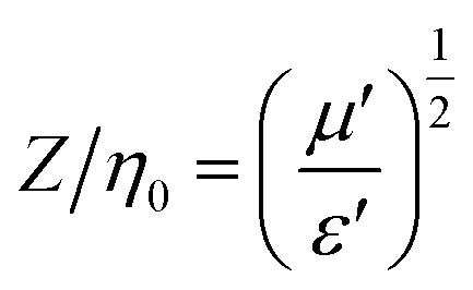
Matching magneto-dielectric properties of ferrites determine the ability of the materials to be used in miniaturizing of device applications. The ratio between permeability and permittivity over a wide range of frequencies is used to estimate the properties. Therefore, transmission wavelength (λ) inside the studied samples was calculated from the related frequency (f) by the formula:77| |
 | (8) |
where c = 3 × 10⁸ m s−1 (the velocity of light), εr is the relative permittivity, ε′ is the real permittivity, μr is the relative permeability and μ′ is the real permeability. Moreover, the matching impedance (Z/η0) was calculated from the ratio of μ′ and ε′ by the formula,| |
 | (9) |
where Z is the impedance of antenna substrates suggested by the studied samples and η0 is the impedance for air. Therefore, a suitable miniaturizing device must follow the relation μ′/ε′ ≈ 1 to attain Z ≈ η0. Fig. 13(a) and (b) show the frequency-dependent Z/η0 ratio and λ, respectively, for Ni0.7Zn0.2Co0.1Fe2−xGdxO4 (0 ≤ x ≤ 0.12) samples and the frequency range is from 0.10 to 100 MHz). The enhancement of the overall ratio (Z/η0) is observed due to Gd3+ substitution in Ni–Zn–Co ferrite. The highest and stable value of Z/η0 (∼1.62) is observed in the sample for x = 0.10 while it is nearly 1.60 for x = 0.12 and the stability is over a wide frequency range (390 kHz to 30 MHz). The other samples have a lower stability in the Z/η0. Hence, the sample for x = 0.10 is expected to be excellent for miniaturizing-device applications over a wide range of 390 kHz to 30 MHz. Moreover, the values of λ having a minimum value in the proposed frequency range as shown in Fig. 13(b).
 |
| | Fig. 13 (a) Frequency-dependent Z/η0 values and (b) Transmission wavelength (λ) for Ni0.7Zn0.2Co0.1Fe2−xGdxO4 (0 ≤ x ≤ 0.12) samples at RT (300 K). | |
4. Conclusion
A single-phase spinel ferrite with composition Ni0.7Zn0.2Co0.1Fe2−xGdxO4 (0 ≤ x ≤ 0.12) was successfully synthesized by a low-cost double sintering method. The sample structures correspond to the Fdm space group and the average grain size decreases from 81.7 nm to 42.9 nm due to the substitution of Gd3+ at Fe3+ of the B-site. Furthermore, an impurity phase of γ-Fe2O3 exists in undoped Ni–Zn–Co ferrite, which has been eliminated by Gd3+ substitution, except for x = 0.10. The binding force between the atoms of spinel lattice of the studied samples increases for Gd3+ substitution in Ni–Zn–Co ferrite and remains unchanged for 0.07 ≤ x ≤ 0.12 samples. Moreover, lattice vibrations are hindered due to Gd3+ substitution. The magnetic permeability (μ′) decreases with increasing Gd3+ content in the compositions. In addition, the exchange interaction, J, for the A–B sublattice is proportional to TC and gradually decreases for Gd3+ substitution concomitant with the reduction of lattice constants. The DC resistivity (ρDC) at RT increased from 6.2 × 10⁻³ Ω m to 2.2 × 10⁶ Ω m with increasing Gd3+ substitution and lowering of the eddy current loss is expected. An electronic transition temperature (TEC) near RT is observed in all samples and the activation energy (E2) after TEC is lower than the activation energy (E1) before TEC for 0.0 ≤ x ≤ 0.07 samples. The maximum TCR value (−12% K−1 at 522 K) is found for the x = 0.10 sample and may be applied as an infrared detector for night vision bolometer material. Apart from this, below 20 Hz all samples are completely resistive, while above 100 Hz, inductive properties are achieved. The conduction relaxation processes are spread over an extensive range of frequencies as more Fe3+ ions are replaced by Gd3+. The highest and stable value of matching impedance (Z/η0 ∼ 1.62) is observed in the sample for x = 0.10 while it is nearly 1.60 in the sample for x = 0.12 and the stability is over a wide frequency range (390 kHz to 30 MHz). Hence, the composition for x = 0.10 is expected to be excellent for the miniaturizing-device application over a wide range of frequencies and the transmission wavelength (λ) also reaches a minimum value in this frequency range.
Conflicts of interest
There is no conflict of interest.
References
- V. G. Harris, A. Geiler, Y. J. Chen, S. D. Yoon, M. Z. Wu, A. Yang, Z. H. Chen, P. He, P. V. Parimi, X. Zuo, C. E. Patton, M. Abe, O. Acher and C. Vittoria, Recent Advances in Processing and Applications of Microwave Ferrites, J. Magn. Magn. Mater., 2009, 321, 2035 CrossRef CAS.
- S. J. Yoon, S. Mallidi, J. M. Tam, J. O. Tam, A. Murthy, K. P. Johnston, K. V. Sokolov and S. Y. Emelianov, Utility of biodegradable plasmonic nanoclusters in photoacoustic imaging, Opt. Lett., 2010, 35(22), 3751–3753 CrossRef CAS PubMed.
- Y. F. Chen, D. Spoddig, M. Ziese and “, Epitaxial thin film ZnFe2O4: a semi-transparent magnetic semiconductor with high Curie temperature, J. Phys. D: Appl. Phys., 2008, 41, 205004 CrossRef.
- L. Wu, P.-O. Jubert and D. Berman, Monolayer Assembly of Ferrimagnetic CoxFe3–xO4 Nanocubes for Magnetic Recording, Nano Lett., 2014, 14(6), 3395–3399 CrossRef CAS PubMed.
- B. Rabi, A. Essoumhi, M. Sajieddine, J. M. Greneche, E. K. Hlil, A. Razouk and M. A. Valente, Structural, magnetic and magnetocaloric study of Ni0.5Zn0.5Fe2O4 spinel, Appl. Phys. A: Mater. Sci. Process., 2020, 126, 174 CrossRef CAS.
- D. S. Mathew, R.-S. Juang and “, An overview of the structure and magnetism of spinel ferrite nanoparticles and their synthesis in microemulsions, Chem. Eng. J., 2007, 129, 51–65 CrossRef CAS.
- B. D. Cullity, Introduction to magnetic materials, Wiley, New Jersey, 2009 Search PubMed.
- L. Kumar, P. Kumar, A. Narayan and M. Kar, Rietveld analysis of XRD patterns of different sizes of nanocrystalline cobalt ferrite, Int. Nano Lett., 2013, 3(8), 1–12 Search PubMed.
- J.-M. Li, X.-L. Zeng and Z.-An Xu, Partial cationic inversion-induced magnetic hardening of densely packed 23-nm-sized nanocrystallite-interacting nickel ferrite electrospun nanowires, Appl. Phys. Lett., 2013, 103, 232410 CrossRef.
- Y. Li, L. Xu, X. Li, X. Shen and A. Wang, Effect of aging time of ZnO sol on the structural and optical properties of ZnO thin films prepared by sol-gel method, Appl. Surface Sci., 2010, 256, 4543–4547 CrossRef CAS.
- G. Datt, M. Sen Bishwas, M. Manivel Raja and A. C. Abhyankar, Observation of magnetic anomalies in one-step solvothermally synthesized nickel-cobalt ferrite nanoparticles, Nanoscale, 2016, 8, 5200–5213 RSC.
- Z. Beji, L. S. Smiri, N. Yaacoub, J.-M. Gren`eche, N. Menguy, S. Ammar and F. Fiévet, Annealing Effect on the Magnetic Properties of Polyol-made Ni-Zn Ferrite Nanoparticles, Chem. Mater., 2010, 22, 1350–1366 CrossRef CAS.
- E. Hutamaningtyas, S. Utari, A. T. Wijayanta and B. Purnama, FTIR and structural properties of co-precipitated cobalt ferrite nanoparticles, J. Phys.: Conf. Ser., 2016, 776, 012023 CrossRef.
- Z. Zhang, Y. Liu, G. Yao, G. Zu, X. Zhang and J. Ma, Solid-state reaction synthesis of NiFe2O4 nanoparticles by optimizing the synthetic conditions, Phys. E, 2012, 45, 122–129 CrossRef CAS.
- A. K. M. Akther Hossain, S. T. Mahmud, M. Seki, T. Kawai and H. Tabata, Structural, Electrical Transport and Magnetic Properties of Ni1−xZnxFe2O4, J. Magn. Magn. Mater., 2007, 312, 210–219 CrossRef.
- J. P. Chen, C. M. Sorenven, K. J. Kalbunde, G. C. Hadjipanayis, E. Devli and A. Koshikas, Size-dependent magnetic properties of MnFe2O4 fine particles synthesized by coprecipitation, Phys. Rev. B, 1966, 54, 9288 CrossRef PubMed.
- J. B. Da Silva and N. D. S. Mohallan, Preparation of composites of nickel ferrites dispersed in silica matrix, J. Magn. Magn. Mater., 2001, 226–230, 1393–1396 CrossRef CAS.
- A. M. Abdeen, Electric conduction in Ni-Zn ferrites, J. Magn. Magn. Mater., 1998, 185(2), 199–206 CrossRef CAS.
- M. Tan, Y. Köseoğlu, F. Alan and E. Sentürk, Overlapping large polaron tunneling conductivity and giant dielectric constant in Ni0.5Zn0.5Fe1.5Cr0.5O4 nanoparticles (NPs), J. Alloys Compd., 2011, 509, 9399–9405 CrossRef CAS.
- S. K. Pradhan, S. Bid, M. Gateshki and V. Petkov, Microstructure characterization and cation distribution of nanocrystalline magnesium ferrite prepared by ball milling, Mater. Chem. Phys., 2005, 93, 224–230 CrossRef CAS.
- P. Dolcet, K. Kirchberg, A. Antonello, C. Suchomski, R. Marschall, S. Diodati, R. Muñoz-Espí, K. Landfester and S. Gross, Exploring wet chemistry approaches to ZnFe2O4 spinel ferrite nanoparticles with different inversion degrees: a comparative study, Inorg. Chem. Front., 2019, 6, 1527–1534 RSC.
- S. M. Hoque, M. A. Choudhury and M. F. Islam, Characterization of Ni-Cu Mixed Spinel Ferrites, J. Magn. Magn. Mater., 2002, 251, 292–303 CrossRef CAS.
- M. Veverka, Z. Jirák, O. Kaman, K. Knížek, M. Maryško, E. Pollert, K. Závěta, A. Lančok, M. Dlouhá and S. Vratislav, Distribution of cations in nanosize and bulk Co–Zn ferrites, Nanotechnology, 2011, 22, 345701 CrossRef CAS PubMed.
- M. Niyaifar, Effect of preparation on the structure and magnetic properties of ZnFe2O4, J. Magn., 2014, 19, 101–105 CrossRef.
- S. A. Oliver, V. G. Harris, H. H. Hamdeh and J. C. Ho, Large zinc cation occupancy of octahedral sites in mechanically activated zinc ferrite powders, Appl. Phys. Lett., 2000, 76, 2761–2763 CrossRef CAS.
- G. A. Sawatzky and F. Van Der Woude, A H Morrish “Mössbauer study of several ferrimagnetic spinels, Phys. Rev., 1969, 187, 747 CrossRef CAS.
- J. Smith and H. P. J. Wijn, Ferrites, Jhon -Wiley, New york, 1959 Search PubMed.
- K. Jalaiah, K. Chandra Mouli, R. V. Krishnaiah, K. Vijaya Babu and P. S. V. Subba Rao, The structural, DC resistivity and magnetic properties of Zr and Co co-substituted Ni0.5Zn0.5Fe2O4, Heliyon, 2019, 5, 01800 CrossRef PubMed.
- B. Parvatheeswara Rao and O. F. Caltun, Microstructure and magnetic behaviour of Ni-Zn-Co ferrites, J. Optoelectron. Adv. Mater., 2006, 8, 995–997 Search PubMed.
- I. Mikami, Role of induced anisotropy in magnetic spectra of cobalt-substituted nickel-zinc ferrites'’, Japan, J. App. Phys., 1973, 12(5), 678–693 CrossRef CAS.
- A. M. Abdeen, Structural, magnetic and electrical properties of the sol-gel prepared Li0.5Fe2.5O4 fine particles, J. Magn. Magn. Mater., 1998, 185, 199–206 CrossRef CAS.
- M. Jalaly, M. H. Enayati, P. Kameli and F. Karimzadeh, Effect of composition on structural and magnetic properties of nanocrystalline ball-milled Ni1−xZnxFe2O4 ferrite, Physica B, 2010, 405, 507–512 CrossRef CAS.
- P. S. A. Kumar, J. J. Shrotri, S. D. Kulkarni, C. E. Deshpande and S. K. Date, Low-temperature synthesis of Ni0.8Zn0.2Fe2O4 powder and its characterization, Mater. Lett., 1996, 27, 293–296 CrossRef.
- A. K. M. Akther Hossain, M. Seki, T. Kawai and H. Tabata, Colossal magnetoresistance in spinel-type Zn1−xNixFe2O4, J. App. Phys., 2004, 96, 1273–1275 CrossRef CAS.
- E. Girgis, M. MS Wahsh, A. GM Othman, L. Bandhu and K. V. Rao, Synthesis, magnetic and optical properties of core/shell Co1-xZnxFe2O4/SiO2 nanoparticles, Nano. Rese Lett., 2011, 6(1), 460 CrossRef PubMed.
- N. Rezlescu, E. Rezlescu, P. D. Popa and L. Rezlescu, Structural and physical properties of Ni–Tb–Fe–O system, J. Alloys Compd., 1998, 275–277, 657–659 CrossRef CAS.
- V. A. Brabers, Ferrimagnetic insulators,” in Handbook of Magnetism and Advanced Magnetic Materials, John Wiley & Sons, New York, USA, 2007 Search PubMed.
- M. Wu and A. Hoffmann, Recent Advances in Magnetic Insulators from Spintronics to Microwave Applications', Elsevier, Academic Press, San Diego, Calif, USA, 2013 Search PubMed.
- J. Smit and H. P. J. Wijn, Ferrites, Philips Technical Library, Eindhoven, Netherlands, 1959 Search PubMed.
- K. Kamala Bharathi, J. Arout Chelvana and G. Markandeyulu, Magnetoelectric Properties of Gd and Nd-Doped Nickel Ferrite, J. Magn. Magn. Mater., 2009, 321, 3677 CrossRef CAS.
- K. Kamala Bharathi, K. Balamurugan, P. N. Santhosh, M. Pattabiraman and G. Markandeyulu, Magnetocapacitance in Dy-Doped Ni Ferrite, Phys. Rev. B, 2008, 77, 172401 CrossRef.
- M. D. Hossain, M. N. I. Khan, A. Nahar, M. A. Ali, M. A. Matin, S. M. Hoque, M. A. Hakim and A. T. M. K. Jamil, Tailoring the properties of Ni-Zn-Co ferrites by Gd3+ substitution, J. Magn. Magn.Mater., 2020, 497, 165978 CrossRef CAS.
- P. G. Hewitt, Conceptual Physics, Harper Collins College Publishers, New York, USA, 7th edn, 1993 Search PubMed.
- H. M. “ Rietveld, A profile refinement method for nuclear and magnetic structures, J. Appl. Crystallogr., 1969, 2, 65–71 CrossRef CAS.
- S. Bid and S. K. Pradhan, Preparation and microstructure characterization of ball-milled ZrO2 powder by the Rietveld method: monoclinic to cubic phase transformation without any additive, J. Appl. Crystallogr., 2002, 35, 517–525 CrossRef CAS.
- V. Patil, S. E. Shirsath, S. More, S. Shukla and K. Jadhav, Effect of zinc substitution on structural and elastic properties of cobalt ferrite, J. Alloys Compd., 2009, 488, 199–203 CrossRef CAS.
- M. H. Sousa, F. A. Tourinho and J. C. Rubim, Use of Raman micro-spectroscopy in the characterization of MIIFe2O4 (M=Fe, Zn) electric double layer ferrofluids, J. Raman Spectrosc., 2000, 31, 185–191 CrossRef CAS.
- J. R. Scheffe, M. D. Allendorf, E. N. Coker, B. W. Jacobs, A. H. McDaniel and A. W. Weimer, Hydrogen Production via Chemical Looping Redox Cycles Using Atomic Layer Deposition-Synthesized Iron Oxide and Cobalt Ferrites, Chem. Mater., 2011, 23, 2030–2038 CrossRef CAS.
- K. Mohit, V. R. Gupta and S. K. Rout, Magnetic properties and DC electrical resistivity studies on cadmium substituted nickel-zinc ferrite system, Prog. Electromagn. Res. B, 2014, 57, 157–175 CrossRef.
- T.-J. Park, G. C. Papaefthymiou, A. J. Viescas, A. R. Moodenbaugh and S. S. Wong, Size-dependent magnetic properties of single-crystalline multiferroic BiFeO3 nanoparticles, Nano Lett., 2007, 7, 766–772 CrossRef CAS PubMed.
- N. Singh, A. Agarwal and S. Sanghi, Dielectric relaxation, conductivity behavior and magnetic properties of Mg substituted Zn-Li ferrites, Curr. Appl. Phys., 2011, 11(3), 783–789 CrossRef.
- J. Jiang, L. Li and F. Xu, Structural Analysis and Magnetic Properties of Gd-Doped Li-Ni Ferrites Prepared Using Rheological Phase Reaction Method, J. Rare Earths, 2007, 25, 79–83 CrossRef.
- S. Sharma, V. Singh and R. K. Kotnala, et al., Comparative studies of pure BiFeO3 prepared by sol-gel versus conventional solid-state-reaction method, J. Mater. Sci.: Mater. Electron., 2014, 25, 1915–1921 CrossRef CAS.
- J. Massoudi, M. Smari, K. Nouri, E. Dhahri, K. Khirouni, S. Bertaina, L. Bessaisc and E. K. Hlil, Magnetic and spectroscopic properties of Ni-Zn- Al ferrite spinel: from the nanoscale to microscale, RSC Adv., 2020, 10, 34556 RSC.
- E. Hutamaningtyas, S. Utari, A. T. Wijayanta and B. Purnama, FTIR and structural properties of co-precipitated cobalt ferrite nanoparticles, J. Phys.: Conf. Ser., 2016, 776, 012023 CrossRef.
- W. A. Wooster, Physical properties and atomic arrangements in crystals, Rep. Prog. Phys., 1953, 16, 62 CrossRef.
- C. Zener, Elasticity and Anelasticity of Metals, University of Chicago, Chicago, 1948 Search PubMed.
- D. Bouokkeze, J. Massoudi, W. Hzez, M. Smari, A. Bougoffa, K. Khirouni, E. Dhahri and L. Bessais, Investigation of the structural, optical, elastic and electrical properties of spinel LiZn2Fe3O8 nanoparticles annealed at two distinct temperatures, RSC Adv., 2019, 9, 40940–40955 RSC.
- S. A. Mazen, S. F. Mansour, E. Dhahri, H. M. Zaki and T. A. Elmosalami, The infrared absorption and dielectric properties of Li–Ga ferrite, J. Alloys Compd., 2009, 470, 294–300 CrossRef CAS.
- S. S. Bhatu, V. K. Lakhani, A. R. Tanna, N. H. Vasoya, J. U. Buch, P. U. Sharma, U. N. Trivedi, H. H. Joshi and K. B. Modi, Effect of nickel substitution on structural, infrared and elastic properties of lithium ferrite, Indian J. Pure Appl. Phys., 2007, 45, 596–608 CAS.
- M. R. Hassan, Md. Sarowar Hossain, M. A. Hakim, M. A. Matin, M. N. I. Khan and S. S. Sikder, Structural effect on Magneto-electric properties in (1-x)BiFe0.9La0.1O3 + xNi0.6Zn0.4Fe1.94V0.06O4 composites, Results Phys., 2021, 26, 104340 CrossRef.
- K. Jalaiah, K. Chandra Mouli, R. V. Krishnaiah, K. Vijaya Babu and P. S. V. Subba Rao, The structural, DC resistivity and magnetic properties of Zr and Co co-substituted Ni0.5Zn0.5Fe2O4, Heliyon, 2019, 5, 01800 CrossRef PubMed.
- K. K. Bestha, J. J. Abraham, J. A. Chelvane and V. Gorige, Influence of cation distribution on magnetic response of polycrystalline Co1−xNixFe2O4(0≤x≤1) ferrites, Phys. Scr., 2020, 95, 085802 CrossRef CAS.
- S. M. Patange, S. E. Shirsath, G. S. Jangam, K. S. Lohar, S. S. Jadhav and K. M. Jadhav, Rietveld structure refinement, cation distribution and magnetic properties of Al3+ substituted NiFe2O4 nanoparticles, J. Appl. Phys., 2011, 109, 053909 CrossRef.
- U. B. Gawas, V. M. S. Verenkar and S. C. Mojumdar, Synthesis and characterization of Ni0.6Zn0.4Fe2O4 nanoparticles obtained by autocatalytic thermal decomposition of carboxylate-hydrazine complex, J. Therm. Anal. Calorim., 2011, 104, 879–883 CrossRef CAS.
- K. V. Chandekar and K. M. Kant, Relaxation phenomenon and relaxivity of cetrimonium bromide (CTAB) coated CoFe2O4 nanoplatelets, Phys. B, 2018, 545, 536–548 CrossRef CAS.
- E. J. W. Verwey and J. H. de Boer, Cation arrangement in a few oxides with crystal structures of the spinel-type, Recl. Trav. Chim. Pays-Bas, 2010, 55, 531–540 CrossRef.
- A. Lakshman, P. S. V. S. Rao, B. P. Rao and K. H. Rao, Electrical properties of In3+ and Cr3+ substituted magnesium–manganese ferrites, J. Phys. D: Appl. Phys., 2005, 38, 673–678 CrossRef CAS.
- M. Raghasudha, D. Ravinder, P. Veerasomaiah, K. M. Jadhav, M. Hashim, P. Bhatt and S. S. Meena, Electrical resistivity and Mössbauer studies of Cr substituted Co nano ferrites, J. Alloys Compd., 2017, 694, 366–374 CrossRef CAS.
- E. Stefan, P. A. Connor, A. K. Azad and J. T. S. Irvine, Structure and properties of MgMxCr2xO4 (M = Li, Mg, Ti, Fe, Cu, Ga) spinels for electrode supports in solid oxide fuel cells, J. Mater. Chem. A, 2014, 2, 18106–18114 RSC.
- B. P. Rao and K. H. Rao, Effect of sintering conditions on resistivity and dielectric properties of Ni-Zn ferrites, J. Mater. Sci., 1997, 32, 6049–6054 CrossRef CAS.
- E. J. W. Verwey and P. W. Haayman, Electronic conductivity and transition point of magnetite (“Fe3O4”), Physica, 1941, 8, 979–987 CrossRef CAS.
- A. A. Sattar, H. M. El-Sayed and M. M. El-Tabey, The effect of Al-substitution on the structure and electrical properties of MnNi-Zn ferrites, J. Mater. Sci., 2005, 40, 4873–4879 CrossRef CAS.
- H. Chouaya, M. Smari, I. Walha, E. Dhahri, M. P. F. Graça and M. A. Valente, The effect of bismuth on the structure, magnetic and electric properties of Co2MnO4 spinel multiferroic, J. Magn. Magn. Mater., 2018, 451, 344–350 CrossRef CAS.
- J. T. S. Irvine, A. Huanosta, R. Velenzuela and A. R. West, Electrical Properties of Polycrystalline Nickel Zinc Ferrites, J. Am. Ceram. Soc., 1990, 73, 729 CrossRef CAS.
- V. F. Lvovich, Impedance Spectroscopy, Applications to Electrochemical and Dielectric Phenomena, John Wiley & Sons, Inc., 2012 Search PubMed.
- Y. Peng, X. Wua, Z. Chen, W. Liu, F. Wang, X. Wang, Z. Feng, Y. Chen and V. G. Harris, BiFeO3 tailored low loss M-type hexaferrite composites having equivalent permeability and permittivity for very high-frequency applications, J. Alloys Compd., 2015, 630, 48–53 CrossRef CAS.
Footnote |
| † Electronic supplementary information (ESI) available. See DOI: 10.1039/d1ra04762k |
|
| This journal is © The Royal Society of Chemistry 2022 |
Click here to see how this site uses Cookies. View our privacy policy here. 
 Open Access Article
 This Open Access Article is licensed under a Creative Commons Attribution-Non Commercial 3.0 Unported Licence
 c,
R. Rashidc,
M. A. Hakimd and
M. N. I. Khan
c,
R. Rashidc,
M. A. Hakimd and
M. N. I. Khan 46 The values of HT and HO are illustrated in Fig. 1(c) and found to be concomitant with a and d.


 for both octahedral and tetrahedral sites. Fig. 4(b) and (c) show the variation of the force constant of the Fe–O bond and its bond length, respectively, due to Gd3+ substitution in place of Fe3+. It is observed that both kFe–OO and kFe–OT are maximum for the sample x = 0.07, wherein, the Fe–O bond length is minimum. Again, the overall force constants of ions at the octahedral site (kO) and tetrahedral site (kT) are expressed as54,55
 In a recent study on Ni–Zn–Al ferrite, Jalel Massoudi et al.54 reported that kT was found to decrease while kO increases. In our present system, this trend is followed by the samples 0.07 ≤ x ≤ 0.12 while the force constants for both tetrahedral and octahedral sites increase for the sample 0.00 ≤ x ≤ 0.07 shown in Fig. 4(d). In addition, the binding force between atoms of the spinel lattice of the studied samples due to Gd3+ substitution was evaluated from the variation of Young's modulus (E), rigidity modulus (G) and Poisson's ratio (σ), as discussed in an earlier report of Wooster's work.56 Here, the elastic constants have been estimated from the average force constant (kav) as discussed in the supplementary part. The Poisson's ratios (σ), as depicted in Table 2 are observed to diverge from 0.29 to 0.31 depending on the compositions and the values lie in the range from −1 to 0.5, which is consistent with the theory of isotropic elasticity. However, the Zener anisotropy factor,57 A as shown in Table 2 yields deviations less than unity signifying the degree of anisotropy. Moreover, the obtained values of stiffness (C12) are positively ranging from 81.59 GPa to 86.55 GPa depending on the compositions and indicating the stability of the synthesized Gd-doped Ni–Zn–Co ferrite. Fig. 5(a) shows the variation of E and G due to Gd3+ substitution in Ni–Zn–Co ferrite, which is found to be increasing sharply with increasing Gd amount up to x = 0.05 and then drops to a lower value for x = 0.07. However, more amount of Gd3+ substitution (0.07 ≤ x ≤ 0.12) could not improve E and G remarkably, except a slight increase of x = 0.07. The overall variations of elastic moduli change concomitantly with the bond lengths between ions as shown in Fig. 4(c) and (e) and it is confirmed that the interatomic bonding between cations is getting strengthened up to x = 0.05 and above x = 0.07.


 with the variation of temperature.