
 Open Access Article
 This Open Access Article is licensed under a
 Creative Commons Attribution 3.0 Unported Licence
Mapping short-range order at the nanoscale in metal–organic framework and inorganic glass composites†
Joonatan E. M.
Laulainen
 *a,
Duncan N.
Johnstone
a,
Ivan
Bogachev
a,
Louis
Longley
a,
Courtney
Calahoo
b,
Lothar
Wondraczek
b,
David A.
Keen
c,
Thomas D.
Bennett
a,
Sean M.
Collins
*ad and
Paul A.
Midgley
*a
*a,
Duncan N.
Johnstone
a,
Ivan
Bogachev
a,
Louis
Longley
a,
Courtney
Calahoo
b,
Lothar
Wondraczek
b,
David A.
Keen
c,
Thomas D.
Bennett
a,
Sean M.
Collins
*ad and
Paul A.
Midgley
*a
aDepartment of Materials Science and Metallurgy, University of Cambridge, 27 Charles Babbage Road, Cambridge CB3 0FS, UK. E-mail: jeml3@cam.ac.uk; pam33@cam.ac.uk
bOtto Schott Institute of Materials Research, Friedrich Schiller University Jena, Fraunhoferstrasse 6, 07743 Jena, Germany
cISIS Facility, Rutherford Appleton Laboratory, Harwell Campus, Didcot OX11 0QX, UK
dBragg Centre for Materials Research, School of Chemical and Process Engineering and School of Chemistry, University of Leeds, Leeds LS2 9JT, UK. E-mail: S.M.Collins@leeds.ac.uk
First published on 21st October 2022
Abstract
Characterization of nanoscale changes in the atomic structure of amorphous materials is a profound challenge. Established X-ray and neutron total scattering methods typically provide sufficient signal quality only over macroscopic volumes. Pair distribution function analysis using electron scattering (ePDF) in the scanning transmission electron microscope (STEM) has emerged as a method of probing nanovolumes of these materials, but inorganic glasses as well as metal–organic frameworks (MOFs) and many other materials containing organic components are characteristically prone to irreversible changes after limited electron beam exposures. This beam sensitivity requires ‘low-dose’ data acquisition to probe inorganic glasses, amorphous and glassy MOFs, and MOF composites. Here, we use STEM-ePDF applied at low electron fluences (10 e− Å−2) combined with unsupervised machine learning methods to map changes in the short-range order with ca. 5 nm spatial resolution in a composite material consisting of a zeolitic imidazolate framework glass agZIF-62 and a 0.67([Na2O]0.9[P2O5])–0.33([AlO3/2][AlF3]1.5) inorganic glass. STEM-ePDF enables separation of MOF and inorganic glass domains from atomic structure differences alone, showing abrupt changes in atomic structure at interfaces with interatomic correlation distances seen in X-ray PDF preserved at the nanoscale. These findings underline that the average bulk amorphous structure is retained at the nanoscale in the growing family of MOF glasses and composites, a previously untested assumption in PDF analyses crucial for future non-crystalline nanostructure engineering.
Introduction
Non-crystalline nanomaterials are a complex and increasingly significant group of modern materials1 with unique mechanical, catalytic, electrical, and magnetic properties.2–4 These materials consist of systems of non-crystalline nano-domains without long-range structural order, and complex functional and mechanical properties arise particularly from heterogeneous structural domains in multi-component amorphous–amorphous composites.5,6 Despite the lack of long-range structure, the properties and functionality of these non-crystalline composites are directly related to their molecular structure, the pertinent nanoscale phases, and the emergent interfaces. Diffraction techniques commonly used to characterize crystalline nanomaterials are not applicable due to the absence of long-range periodicity in these materials, often termed the “Nanostructure Problem”.7 Total scattering methods such as pair distribution function (PDF) analysis provide a key route to solving this problem.8 However, traditional implementations of these methods yield limited information when applied to heterogenous systems of non-crystalline nanovolumes, as it is exceedingly difficult to unmix the component PDFs of a multi-component, heterogeneous mixture. While recent work has suggested this unmixing is possible when a series of compositions is available,9 local, spatially resolved measurements from constituent single phase domains provide another, more general solution to this signal separation and unmixing problem.Amorphous composites with microscopic to nanoscale variation encompass bulk metallic glasses,10,11 ceramic composites such as those prepared by sintering,12–14 phase separation processes in silicate glasses,15,16 nanoscale dispersions,17 and polymers and polymer blends.18 The recent development of metal–organic framework (MOF) glasses,19,20 a novel category of glasses, has motivated investigation of the blending,21 flux melting22 and crystal–glass composite formation23 within the MOF glass family. Blending and composite-formation of MOF glasses have been identified as routes to solve the immense challenge of producing bulk MOF glasses with reproducible, controlled properties in volumes beyond a few mm3, typically limited by the interplay of melting and thermal decomposition. These multi-component materials have demonstrated intermediate mechanical properties,24 improved gas uptake,25 and enhanced chemical stability26 linked to the close interfacial contact between components. Characterizing the structural ordering across component phases is therefore central to their emerging functional properties.
MOFs, which consist of metal ion or cluster nodes connected by organic linkers in extended three-dimensional networks, have seen widespread development in crystalline form, driven by potential applications emerging from their exceptional designable microporosity, such as for gas storage,27 gas separation,28 catalysis,29 drug delivery30 and water harvesting.31 This microporosity can be designed through chemical and structural variation.32 Engineering defects and disorder33 has introduced further tuning, such as improving accessible surface area in Fe-BTC34 or by creating coordinatively unsaturated metal sites for catalysis or guest binding in separation processes.35 Amorphous and glassy MOFs represent a further extension to long range disorder while preserving the connectivity and local coordination chemistry characteristic of MOFs. Classically, X-ray and neutron PDF has played an integral part in characterizing both amorphous MOFs as well as varying degrees of disorder in MOF crystals.24,35–37
The introduction of multi-component MOF glass-derived composite structures, however, poses a significant challenge to unambiguous structural characterization due to PDF signals containing unresolved and overlapping features from the constituent phases. Moreover, important questions on the length scale of interface structures remain unresolved when no single-phase measurements can be obtained. Here, electron PDF in the scanning transmission electron microscope (STEM-ePDF) unveils the short-range order (SRO) features of the constituent phases within particles of an inorganic glass/MOF glass composite, a hybrid amorphous composite. The spatial resolution in scanning TEM data addresses key unknowns about the abruptness of interfaces between distinct amorphous domains. This is in improvement to typical bulk PDF measurements, where only some progress has been made in extracting interface correlations from data.9,38–41
As a non-periodic total scattering tool, the PDF is a versatile method of analyzing disordered materials.42 It is directly extracted from scattering data43 and encodes the statistical distribution of interatomic distances in the material. X-ray and neutron PDF techniques have been used extensively, but only reach spatial resolutions of approximately 1 μm.44 More recently, there has been a push to extract PDFs from electron diffraction data,42,45 to take advantage of the strong scattering of electrons and the improved spatial resolution. However, ePDF has typically been implemented in a parallel broad-beam configuration in transmission electron microscopy (TEM) to maximize scattering angle resolution but with concomitant loss in spatial resolution, often constrained in resolution to hundreds of nanometers or more. For MOF glasses, STEM spectroscopies including electron energy loss spectroscopy (EELS)46 and X-ray energy dispersive spectroscopy (EDS)47 have been used to offer nanometer spatial resolution, however these methods rely on chemical variations or specific spectroscopic signatures. By providing a structural imprint, the PDF is also sensitive to non-compositional variation in the material.
‘Four-dimensional’ STEM (4D-STEM) methods, where a two-dimensional (2D) diffraction pattern is acquired at each probe position in a 2D scan of the sample, has seen rapid development with the rise of high speed detectors and increased computational power for analyzing crystallographic information from nanomaterials.48,49 Scanning electron diffraction (SED), a 4D-STEM configuration where a relatively parallel beam (<1 mrad) is used offers a balance between diffraction-space and real-space resolution. SED has been used to analyze a variety of organic structures using very low doses, such as crystalline MOFs,23,50 protein structures,51 and organic semiconductors.52 SED has also been combined with ePDF analysis to provide structural data from amorphous–crystalline composites53 amorphous organic semiconductors54 and metallic glasses55 with a few to 10 nm spatial resolution. However, such studies have so far been unable to work at both low dose (<50 e− Å−2) and high (<10 nm) spatial resolution. Recent advances in high-efficiency direct electron detectors with near zero noise56 have set the stage for work at doses required for MOFs (<20 e− Å−2 (ref. 57)), enabling further application in inorganic and MOF glasses.
Here, we apply STEM-ePDF with a dose of 10 e− Å−2 and a spatial resolution of 5 nm by using a direct electron counting detector and unsupervised machine learning methods to map domains of amorphous structure in composite material consisting of a zeolitic imidazolate framework glass agZIF-62, and a 0.67([Na2O]0.9[P2O5])–0.33([AlO3/2][AlF3]1.5) inorganic glass. The combination of the two components was chosen so that both materials are compatible in terms of their thermal and chemical properties.24 We previously screened a range of MOF-inorganic glass combinations, taking melting temperature and liquid fragility as the primary selection parameters. The chosen combination was the simplest, while still providing mechanical stability and preventing undesired redox interactions at high temperature. The combination is expected to enhance mechanical stability without compromising ionic mobility. However, such analysis is not within the scope of this paper. The ZIF-62 consists of Zn2+ ions connected by imidazolate (Im, C3H3N2−) and benzimidazolate (bIm, C7H5N2−) linkers in a 1![[thin space (1/6-em)]](https://www.rsc.org/images/entities/char_2009.gif) :1.75:0.25 ratio [Zn(Im)1.75(bIm)0.25] with a cag topology in crystalline form. The notation ag is used to denote the amorphous ZIF-62 phase prepared as a glass in keeping with prior notation. STEM-ePDF analyses provide crucial insight into the length scales for structural changes at the interface and for evaluating whether the average bulk structure is retained homogeneously at the nanoscale, both significant characteristics for manipulating the amorphous atomic structure underpinning domain microstructures in these MOF/inorganic glass composites as well as further developments in glass composite materials.
:1.75:0.25 ratio [Zn(Im)1.75(bIm)0.25] with a cag topology in crystalline form. The notation ag is used to denote the amorphous ZIF-62 phase prepared as a glass in keeping with prior notation. STEM-ePDF analyses provide crucial insight into the length scales for structural changes at the interface and for evaluating whether the average bulk structure is retained homogeneously at the nanoscale, both significant characteristics for manipulating the amorphous atomic structure underpinning domain microstructures in these MOF/inorganic glass composites as well as further developments in glass composite materials.
Results and discussion
Fig. 1 presents an illustration of the key steps in acquiring and transforming SED data for STEM-ePDF. These steps can be applied to a single pixel as shown or to an area of pixels in the STEM scan taken as a sum. First, the 2D diffraction pattern is integrated azimuthally to form a diffraction profile I(s), where s is the scattering vector magnitude, taken as s = 2sinθ/λ for scattering semi-angle θ and de Broglie wavelength for the electron beam λ. We adopt the notation commonly used for electron scattering, where s is the scattering vector, compared to Q, with s = Q/2π. I(s) must be normalized to an appropriate atomic scattering factor to obtain the s-multiplied reduced intensity φ(s), defined as: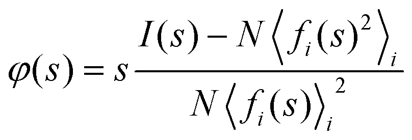 | (1) |
 | (2) |
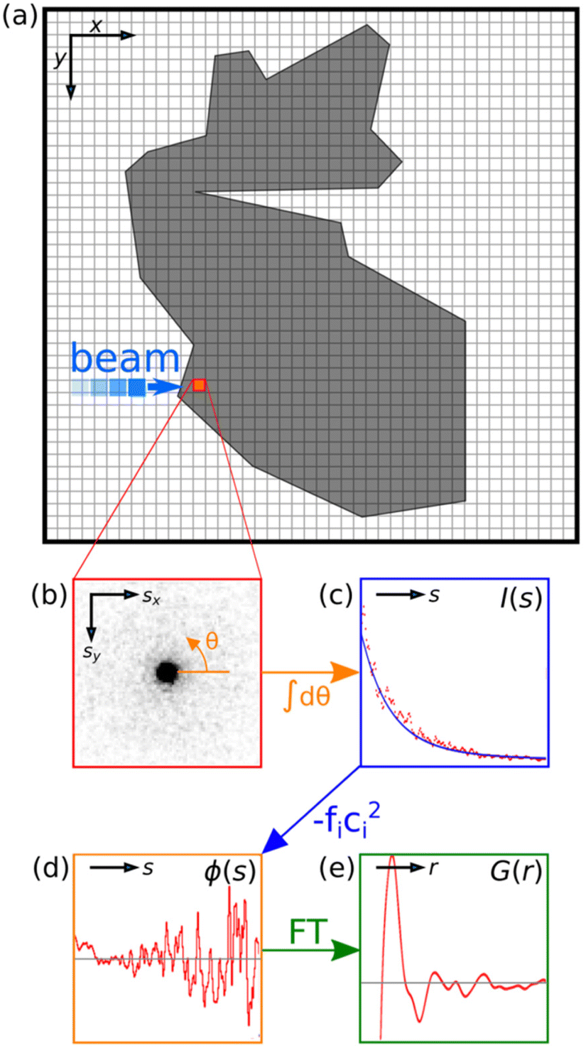 | ||
| Fig. 1 Schematic demonstration of the STEM-ePDF method. (a) A schematic illustration of scanning diffraction. A diffraction pattern is acquired at each pixel in the image, depicted in (b). This diffraction pattern is then integrated azimuthally around θ in the detector plane. (c) The azimuthal integral is fitted to a physically appropriate scattering profile.58 (d) The reduced intensity is acquired by a subtraction of a fitted profile and a subsequent division by a related function (e). | ||
The reduced PDF G(r) is useful as it can be extracted directly from diffraction data without additional specifying the sample density ρ0 and is related to the classical PDF g(r)43 by:
| G(r) = 4πr[g(r) − ρ0] | (3) |
In practice, multiple and inelastic scattering contributions result in an experimental scattering distribution that is fitted poorly by N〈fi(s)2〉i at low and high angles simultaneously59,60 (see Experimental section). To minimize the resulting error in the PDF, N〈fi(s)2〉i is fitted at high s as discussed in previous works.43,61,62 However, there is still a low frequency artifact present, particularly at low s.62 This artifact is parasitic as it is thickness-rather than sample-dependent and so does not reflect the true probability distribution of atomic pair-wise correlations that the PDF measures. The artifact is observable as φ(s) not oscillating about zero. To remedy this, a subsequent polynomial correction detailed by Mu et al.55 was applied to φ(s). While the subsequent φ(s) oscillates about zero, it becomes very noisy at high s due to weak scattering combined with fast acquisition times needed to acquire data at low electron dose in a 4D-STEM configuration. Hence, the data at high s is additionally damped to reduce the impact of termination ripples, resulting in an effective smax of 2.5 Å−1. Subsequently, the central direct beam at zero scattering angle was removed from the data in post-processing, with φ(s) extrapolated from the resultant smin of 0.18 Å−1 to zero.63 The data acquisition and damping process is described in greater detail in the ESI.† The s resolution (Δs) of the recorded data, which is limited by the finite convergence angle of the STEM probe and to a lesser extent the detector (pixel) resolution, also imposes a damping envelope function in the final PDF. Balancing Δs and smax is vital for high quality ePDF data, as they control the extent of the PDF in r and the resolution Δr respectively.64
An SED dataset was acquired on fragments of a composite comprised of agZIF-62 and an inorganic 0.67([Na2O]0.9[P2O5])–0.33([AlO3/2][AlF3]1.5) glass using a JEOL ARM300F operated at 200 kV with a probe size well-approximated by its diffraction limited probe diameter of ca. 5 nm and a convergence semi-angle of ca. 0.6 mrad. The data were recorded on a quad-chip Medipix3 direct electron detector with 512 × 512 pixels at a dose of ca. 10 e− Å−2. After two STEM-ePDF scans, a correlated EDS map was acquired to independently determine the phase distribution. For sufficient counts to be recorded in EDS, the current at the sample was significantly increased accompanied by beam damage but with minimal long-distance displacements of the metal centers that would cause mixing of the two constituent phases in the EDS signal, as shown in previous SED-EDS data on crystalline MOFs.23 The data were subsequently analyzed with the open-source python library Pyxem.65
Electron and X-ray PDF comparison
We first calculated area-averaged STEM-ePDFs through summing multiple diffraction patterns from each separate phase. These ePDFs were scaled and compared to PDFs acquired through X-ray total scattering24 on separate samples made from the same batch of the inorganic glass and agZIF-62, shown in Fig. 2. For both phases, the reduced intensities show agreement in peak positions, though relative intensities exhibit some variation, particularly in the inorganic glass. Some variation in intensity is expected, as the electron and X-ray scattering factors differ (ESI Fig. 1–4†), meaning the two signals encode structural information slightly differently, and smax changed between the two acquisitions. For the inorganic glass, the peak positions at 0.3, 0.7, 0.8, 1.3, and 1.5 Å−1 are all accurately reproduced, although the relative intensities of the peaks at 0.7 and 0.8 Å−1 are reversed with respect to each other (Fig. 2a). The PDF likewise accurately reproduces the primary features, with peaks at 2.6, 4.9, and 6.4 Å present in both the ePDF and xPDF (Fig. 2c). The peaks around 3.5 Å appear broadened in the ePDF relative to the X-ray PDF. For agZIF-62, the peak positions in the reduced intensity at 0.6, 0.8, and 1.0 Å−1 and beyond appear in both electron and X-ray scattering profiles (Fig. 2b). However, the intensities of the low s peaks (<0.8 Å−1) are significantly reduced in the electron data. Peaks in the PDF of agZIF-62 (Fig. 2d) can be assigned to N1–Zn (∼2 Å), C–Zn (N–C–N) (∼3 Å), N2–Zn (∼4 Å) and Zn–Zn (∼6 Å) (N1 and N2 are referenced to a selected Zn atom, with N1 directly coordinated to this Zn and N2 referring to the next nearest N atom to the same Zn),23 with possible additional contributions of N–N distances in particular for 2–3 Å features.66 The remaining peaks are also in the correct positions, although the intensity around 6 Å is reduced in the electron data. A further peak is also present around 5 Å in the ePDF data, which has been seen in other XPDF work.67 We attribute the notable intensity differences around 5 and 6 Å are a result of the relative differences in X-ray and electron scattering, with relatively stronger scattering of the associated Zn–H peaks around 5 Å (ref. 66) and relatively weaker Zn–Zn scattering around 6 Å expected in the electron PDF. Electron and X-ray PDF intensities diverged notably around 5–6 Å for a ZIF-62 crystal (ESI Fig. 5†). The feature changed very slowly with damping factor and smax (ESI Fig. 6 and 7†). Differences in PDFs due to different partial scattering factors are well known between X-ray and neutron PDFs,21,68 but less studied between X-ray and electron PDF. This difference in scattering could be further exploited to characterize the structure further, subject to reduced inelastic and multiple scattering contributions, particularly as the largest differences in scattering among the elements in the sample are seen for features including hydrogen (ESI Fig. 2†). | ||
| Fig. 2 Comparison of reduced intensities φ(s) and reduced PDFs G(r) from X-ray and electron scattering for (a) and (c) the 0.67([Na2O]0.9[P2O5])–0.33([AlO3/2][AlF3]1.5) inorganic glass and (b) and (d) agZIF-62. The electron-derived φ(s) and G(r) are acquired by summing over pixels in a region of known composition. The agZIF-62 φ(s) and G(r) have both been rescaled due to thickness variation (see ESI†). The grey horizontal line marks zero, around which both the structure factor and the reduced PDF oscillate in all plots, with the structure factor going to zero at high s. The peaks for Zn–Zn and N–Zn have been labelled in (d). | ||
Overall, the greatest discrepancies are clearly seen at low s in the reduced intensity φ(s) (Fig. 2b). This is to be expected, as the scattering profiles are fitted to minimize error at high s with its associated higher real-space frequency structural information. One of the effects of this data processing is to overshoot the scattering profile at low s, leading to a stronger damping of the signal there. In addition, some information is lost as a result of removing the direct beam from the electron data, which is larger than in X-ray scattering due to the finite convergence angle and low-angle scattering. The inelastic and multiple scattering that are responsible for the deviation of the average scattering from that calculated by the single atomic scattering factors are largely unavoidable, especially for typical sample thicknesses in the types of composite materials examined here. More quantifiable PDFs will be acquirable on thinner samples with consistent thickness, but micro- and nanoparticle samples often exhibit variable thickness, and it is possible for very thin specimen PDFs to differ from the bulk due to incomplete orientational averaging.64 Further developments in energy filtered SED may offer further reductions in inelastic contributions, improving quantitative comparison with X-ray PDFs. Because significant multiple and inelastic scattering contributions preclude quantification of intensities in the PDFs, we did not fit the acquired ePDFs. However, the general correspondence between X-ray PDFs and STEM-ePDFs demonstrates that identifiable ePDFs can be obtained in total electron scattering. Significantly, the consistency of the bulk X-ray PDF description with nanometer-resolved STEM-ePDF demonstrates a high degree of homogeneity in agZIF-62, which was previously assumed but unverified from ensemble measurements. These results are particularly important for understanding agZIF-62 and its composite formation processes; verification of a consistent bulk and nanoscale structure in composites is typically defined by diffraction in crystalline materials but has not been readily possible in amorphous analogues for MOF glass materials.
Spatially resolved ePDF
The area-averaged ePDFs, despite containing structural information, are limited to the spatial resolution of the area used for averaging, in this case ∼200 nm (Fig. 3a). Still, the ability to construct area-averaged PDFs from user-defined areas post-acquisition is a key benefit of the STEM-ePDF implementation over single-shot TEM-based ePDF. Diffraction patterns from individual probe positions in the STEM scan, in turn, have a low signal-to-noise ratio, such that single PDFs are too noisy to interpret directly. To overcome this problem, we performed a linear matrix decomposition using Principal Component Analysis (PCA)69,70 to extract signals with high variance, followed by an independent component analysis (ICA) blind source separation on the extracted PCA components to convert them into independent additive signals, rather than sums and differences recovered by PCA. The matrix decomposition was performed on the PDFs as they are less susceptible to thickness-variation than the reduced intensities. PCA, ICA, and related unsupervised machine learning matrix factorization approaches have shown success in unmixing signals in ePDF of bulk metallic glasses,71 though at much higher electron doses than used in the present study, as well as in X-ray PDFs of mixture-series with known endmembers.72 Overall, PCA and ICA reduce subjective bias in data analysis, and can be rapidly applied to large data sets, but can occasionally result in incomplete unmixing and therefore do not guarantee the recovery of physical signals.70,73 PCA was applied to a 3D data cube containing the PDFs at each pixel in the scanned area (with pixels rebinned 2 × 2 from originally acquired data to improve signal near smax), revealing two orthogonal structural signal components above the noise floor in the data cube (ESI Fig. 8†). Subsequently, ICA was applied directly to the ePDF data cube for blind source separation of the two components with the largest contribution to the variance to extract statistically independent low-noise ICA-ePDFs, shown in Fig. 3e and f. Additional details of the PCA and ICA are in the ESI.† The ICA-ePDFs were calculated using an average composition of the constituent phases. Use of the average composition did not change peak positions (ESI Fig. 9†). The signals show clear similarity with the area-averaged ePDFs, with identical peak positions reproduced in the ICA-ePDF as in the area averaged data. ICA recovers both ePDF profiles as well as a corresponding map of the linear weights of each component. These spatial distributions recovered by ICA applied to the STEM-ePDF data were further corroborated by comparison with correlated elemental mapping by EDS, showing consistent phase speciation of the atomic structure and the corresponding compositional differences for the agZIF-62 and the 0.67([Na2O]0.9[P2O5])–0.33([AlO3/2][AlF3]1.5) glass. In the ePDFs from ICA, minor variations in peak height are seen around 2–4 Å, likely due to slightly imperfect unmixing of the two signals in this region of high signal overlap, which might be due to the presence of the carbon film (ESI Fig. 10†). ICA assumes linear summation of the separated signals, which is known to be approximate but not entirely precise for PDF analysis.64 In addition, multiple scattering leads to thickness-dependent behavior in the ePDF,60 discussed further below. Nevertheless, the maps of the two signals show agreement with the acquired EDS data as shown in Fig. 3b, yielding a structural map from STEM-ePDF with a 5.5 nm pixel size (Fig. 3c and d).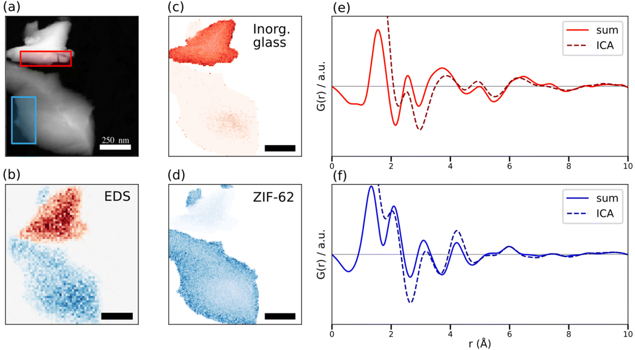 | ||
| Fig. 3 (a) A virtual annular dark field STEM image, constructed from the SED dataset by summing the pixels with 1.5 Å−1< s < 2.5 Å−1 for each real-space pixel. The red and blue rectangles mark the regions used for area-averaged reduced ePDFs in Fig. 2 for the 0.67([Na2O]0.9[P2O5])–0.33([AlO3/2][AlF3]1.5) inorganic glass (red) and agZIF-62 (blue). (b) EDS map of Al (red) and Zn (blue) from the dataset, taken after the STEM-ePDF data. Scale bar 250 nm. An NMF-PCA algorithm was applied for denoising the EDS spectrum.85 (c) and (d) ICA loading maps for (c) the 0.67([Na2O]0.9[P2O5])–0.33([AlO3/2][AlF3]1.5) inorganic glass and (d) agZIF-62. Scale bars 250 nm. (e) and (f) ICA component profiles and area corresponding area-averaged reduced ePDFs for (e) the inorganic glass and (f) agZIF-62. | ||
Multiple and inelastic scattering in ePDF produce a background scattering profile that does not match the expected scattering factor, leading to a variation of the PDF with sample thickness. In amorphous samples, the primary effect of this is to “broaden” reciprocal space peaks leading to PDFs with unchanged peak positions but decreased intensities60 This makes the PDF quite robust to analysis in regimes with thickness changes, as peak positions are typically the primary analytical signal of interest. However, differing peak height with thickness as a function of r results in an ePDF that changes slightly with thickness. Most notably, such variations will not condense to a single factor in ICA due to non-linearity with thickness, visible as decrease in component weighting in the experimental decomposition maps in the thickest regions of the particles (Fig. 3c and d). Unfortunately, while methods to recover single-scattering elastic PDFs have been researched,59,74 they require either accurate estimates of sample thickness, unavailable here due to the annular dark field (ADF) detector setup overlapping with the Medipix camera in the signal range used for PDF analysis, or negligible inelastic scattering, which is not true here due to the thickness. However, it is encouraging that even the significant thickness variation in the particulate sample examined here does not prevent ICA from suitably unmixing phases with interpretable ePDF profiles. A detailed assessment of the variation in the STEM-ePDFs with thickness is included in ESI Fig. 11.†
The dose used in this study (ca. 10 e− Å−2) is of a similar magnitude as observed critical doses in crystalline ZIF structures.75 Complete loss of long-range order, i.e., loss of Bragg diffraction and resultant structural collapse are typically recorded first (<100 e− Å−2). With increasing dose radiolysis is expected to occur in the ZIFs,76,77 accompanied by electron beam-induced mass loss, primarily in the inorganic glass.78 To gauge the loss of structural signal, the same area in Fig. 3 was scanned a second time. Fig. 4 presents area-averaged ePDFs from the first and second STEM scans, showing minimal changes with a total accumulated dose of ca. 20 e− Å−2. Almost all the observed peaks were unchanged, with extremely subtle differences observed around 5 Å in the agZIF-62 and 6.5 Å in the inorganic glass. This suggests the measurements were done before significant damage was caused to the sample structure, considering the correlation with the X-ray PDF in Fig. 2. This stability under the beam is consistent with substantial bond-breaking occurring only at much higher doses. Direct comparisons between critical doses from Bragg diffraction and ePDF may not be possible, but ePDF presents a further tool for assessing damage as a function of dose in amorphous MOFs. The capability for recording multiple sequential scans without detectable changes also holds promise for time-resolved studies of SRO in beam sensitive organic samples using scanning ePDF analysis.
 | ||
| Fig. 4 Area-averaged STEM-ePDF profiles for two scans of the same area for (a) the 0.67([Na2O]0.9[P2O5])–0.33([AlO3/2][AlF3]1.5) inorganic glass and (b) agZIF-62. The grey horizontal lines mark zero on the vertical axes. | ||
In order to demonstrate versatility and repeatability of the STEM-ePDF approach to the analysis of the MOF and inorganic glass composite, we show a second example of the same material in Fig. 5. For this experiment, the detector was limited to only a single 256 × 256 Medipix3 detector. As the scattered data is convolved with the probe function with a non-zero convergence angle, a compromise in the camera length was chosen that increased Δs and decreased smax in comparison to the 512 × 512 dataset. Nonetheless, the acquired ePDFs show clear structural correlation to the ones observed in Fig. 2, although with slightly broader peaks. Once again, peak positions are faithfully reproduced, and the ICA loading maps agree with correlated EDS data. The factors are given in ESI Fig. 12.† Furthermore, a small inclusion of the ZIF-62 in the inorganic glass was observed in both the EDS and the ICA decomposition, noted in Fig. 5e and f. While overlap of two particles cannot be excluded, the two-phase structure appears most likely to be the result of interfacial contact between the agZIF-62 and the inorganic glass, as expected from the bulk composite structure of a closely related set of ZIF-62 inorganic glass composite samples.24 The ICA decomposition of the ePDF signals showed presence of both components, showing that through-thickness variation is encoded in the scattered signal. The ePDFs depicted in Fig. 5 illustrates that STEM-ePDF can offer spatial mapping capabilities with materials-specific signatures in the form of interpretable, though lower quality, PDFs even for sub-optimal (reduced smax) acquisition conditions.
 | ||
| Fig. 5 STEM-ePDF analysis of a second example of the agZIF-62 and 0.67([Na2O]0.9[P2O5])–0.33([AlO3/2][AlF3]1.5) inorganic glass composite material. (a) and (b)Comparisons of area-averaged reduced ePDF profiles obtained using a 512 × 512 pixel detector, for particles shown in Fig. 2–4 and using a 256 × 256 pixel detector, for particles shown in (c)–(d), for (a) the inorganic glass and (b) agZIF-62. (c) EDS map of Al (red) and Zn (blue) from the dataset, taken after the STEM-ePDF data. An NMF-PCA algorithm was applied for denoising the EDS spectra.85 (d) The ICA maps corresponding to reduced ePDF components for the inorganic glass (red) and agZIF-62 (blue). (e) and (f) contrast-adjusted images of the small inclusion of agZIF-62 on the lower particle for (e) EDS and (f) ePDF analyses. | ||
The presence of two phases with a through-thickness overlap invites further investigation of interface characteristics. The presence of an interfacial component in the signal was investigated (ESI Fig. 12†) but no significant structural variation was observed in area-averaged scans or in ICA, suggesting that changes in the SRO are abrupt to within a pixel size of ∼6 nm. This observation is consistent with the expected viscosity and limited mixing of the two phases.24 Interfacial structures are fundamental to the porosity of MOF composite materials as well as their mechanical adhesion and properties.36 However, they have remained a challenge to probe using bulk methods such as X-ray PDF due to them making up only a small fraction of the total probed volume.79 By constraining the interface abruptness with STEM-ePDF and confirming the retention of the atomic structure of the two parent phases in the vicinity of composite interfaces, these findings provide strong, direct evidence that bulk atomic structures in amorphous MOF composites are suitable structural models to within 5–10 nm of the interface.
The low-dose high-resolution acquisition configuration demonstrated here likewise establishes a route to wider application of STEM-ePDF to beam sensitive organic and hybrid materials at room temperature. Previously, ePDF has been applied to the analysis of organic semiconductor blends by Mu et al.54 at 860 e− Å−2 and a crystalline-amorphous blend at cryogenic temperatures by Donohue et al.53 at 60 e− Å−2, compared to our 10 e− Å−2. Furthermore, we were able to achieve high spatial resolution (5 nm) at such low doses by the application of PCA and ICA to extract low-noise component signals. This enables the analysis of non-crystalline and composite materials with critical doses of near 10 e− Å−2. Many organic, polymeric, hybrid and MOF non-crystalline materials properties are governed by both SRO and medium-range order7 and have such low critical doses. Pharmaceutical formulations,72 heterostructures for optoelectronics, and composite materials containing nonperiodic components require low-dose probes for amorphous structural analysis. STEM-ePDF complements other low-dose scanning electron diffraction methods49 and can be operated in parallel to offer a complete structural analysis suite for engineering microstructure in crystalline and non-crystalline materials.
Experimental
Sample preparation
![[thin space (1/6-em)]](https://www.rsc.org/images/entities/b_char_2009.gif) :50 wt% Composites.
Approximately 300 mg crystalline ZIF-62 and 300 mg 0.67([Na2O]0.9[P2O5])–0.33([AlO3/2][AlF3]1.5) powders were mixed together by ball-milling in a Retsch MM400 mixer mill with a 15 ml stainless steel jar and one 5 mm stainless steel ball bearing for 5 minutes at 25 Hz. A 200 mg sample of the ball milled powder mixture was placed in a 13 mm die and compacted into a pellet using 10 tonnes of pressure applied for one minute. This pellet was placed in a tube furnace (Carbolite 12/65/550) which was left to equilibrate under argon for one hour before heating to 410 °C at 10 °C min−1 and holding for 1 minute. All heat treatment was done under constant argon flow. The heat-treated pellet was left to cool under argon at the natural rate of the tube furnace; the sample was removed from the tube furnace at temperatures equal to or below 200 °C.
:50 wt% Composites.
Approximately 300 mg crystalline ZIF-62 and 300 mg 0.67([Na2O]0.9[P2O5])–0.33([AlO3/2][AlF3]1.5) powders were mixed together by ball-milling in a Retsch MM400 mixer mill with a 15 ml stainless steel jar and one 5 mm stainless steel ball bearing for 5 minutes at 25 Hz. A 200 mg sample of the ball milled powder mixture was placed in a 13 mm die and compacted into a pellet using 10 tonnes of pressure applied for one minute. This pellet was placed in a tube furnace (Carbolite 12/65/550) which was left to equilibrate under argon for one hour before heating to 410 °C at 10 °C min−1 and holding for 1 minute. All heat treatment was done under constant argon flow. The heat-treated pellet was left to cool under argon at the natural rate of the tube furnace; the sample was removed from the tube furnace at temperatures equal to or below 200 °C.
Data acquisition
4D-STEM data of a beam-sensitive nanocomposite of amorphous ZIF-62 and amorphous 0.67([Na2O]0.9[P2O5])–0.33([AlO3/2][AlF3]1.5) was acquired on a JEOL ARM300F STEM operated at 200 kV with a beam diameter of ca. 5 nm and a convergence semi-angle of ca. 0.6 mrad. The beam current was 3.4 pA and the frame rate was 1 ms per pattern, with slight overlap between the beam at adjacent pixels, leading to an electron dose of ca. 10 e Å−2, much lower than typically used in STEM imaging.80 The diffraction patterns were acquired using a quad-chip Medipix3 direct electron detector with 512 × 512 pixels and a Δs of 0.011 Å−1. The four constituent read-out electronics are separated by a gap of 3 pixels, resulting in a total detector area equivalent to 515 × 515 pixels and leading to a maximum scattering vector magnitude smax = 2sinθ/λ of 2.8 Å−1. (corresponding to a maximum Qmax = 4πsinθ/λ of 17.6 Å−1). Correlative X-ray energy-dispersive spectroscopy (EDS) was performed subsequently to provide an independent method of confirmation of structural domains, as they correspond to compositional differences. The condenser aperture was opened to increase the current for EDS measurements.
The 256 × 256 patterns were acquired on the same microscope operated at 300 kV using a single Medipix3 direct electron detector with a beam diameter of ca. 5 nm and a convergence semi-angle of ca. 0.6 mrad. The beam current was 4.6 pA and the frame rate was 1 ms per pattern, leading to an electron dose of ca. 13 e Å−2. The single Medipix3 detector had 256 × 256 pixels and a Δs of 0.016 Å−1 leading to a maximum scattering vector smax of 2.1 Å−1 (corresponding to a maximum Qmax of 13.4 Å−1).
Data processing
All data processing steps were carried out using Pyxem 0.10, an open-source Python package.65 Pre-processing was carried out as detailed in Section 1 of the ESI.† The recorded single and area-averaged electron diffraction patterns from the SED data showed no distinct diffraction peaks, only an amorphous halo. The single patterns exhibited a low signal-to-noise ratio due to the low electron dose, with average intensities at high scattering vector less than 0.1 detected electrons per pixel. Nonetheless, azimuthally integrated profiles, integrated using pyFAI81 within Pyxem do show distinct features. The azimuthally integrated profile is denoted I(s), where s is the scattering vector magnitude taken as smax = 2sinθ/λ for scattering semi-angle θ and de Broglie wavelength λ for the electron beam. The reduced pair distribution function43,64 was then obtained from this profile, by first fitting an appropriate composition-dependent atomic scattering factor to obtain the experimental reduced intensity φexp(s), as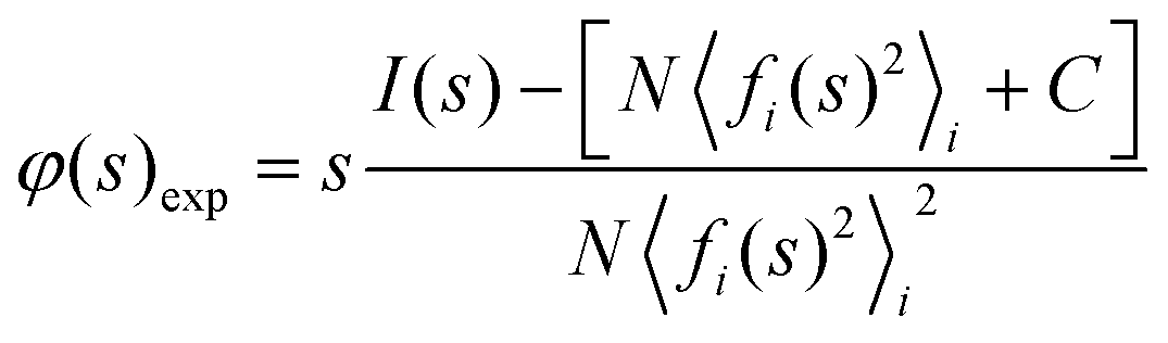 | (4) |
For the spatially resolved calculations, the fitting was initially done with an average composition at every pixel. ICA was still able to distinguish the two structures in the reduced PDF. Once the composition was determined through structural fitting, a more appropriate pixel-wise composition was used to acquire more accurate PDFs. The difference in reduced PDF as a result of fitting an average composition over the correct composition is shown in ESI Fig. 9.†
The fitting process was carried out by specifying the atomic fraction ci and fi(s) for each element, and then fitting the scaling parameter N. However, the fitted intensity does not fit the diffracted intensity at both small and large scattering angles simultaneously in electron diffraction.59,60 This is caused by non-negligible multiple scattering due to specimen thickness and by inelastic scattering, resulting in a change of shape of the single-element scattering factor fi(s). This results in a low-frequency artifact in reciprocal space that in turn results in both a strongly oscillating PDF at small r and a weak low-frequency oscillation at large r.62 These artifacts are parasitic as they do not rise from the real structure of the specimen measured by the PDF and are clearly visible in the reduced intensity as a low frequency artifact that results in the reduced intensity not oscillating about zero. For goodness of fit, the profile was fit to the tail end of the spectrum as suggested in ref. 43 and 62, as the low intensity region errors at high s tend to get exaggerated when extracting the reduced intensity. This is due to a division by the sharpening factor, resulting in larger fractional error. Unfortunately, this is an intrinsic problem in electron diffraction, which is exaggerated when probing nanoparticles as they have a variable thickness.
As a solution to this problem, it has been suggested to use a 4th order polynomial function that goes to zero at s = 0 and s = smax to fit the oscillating reduced intensity after fitting the appropriate atomic scattering factor.61,62 This polynomial shifts the baseline to get a reduced intensity that does, on average, oscillate around zero as it physically should. The PDFs obtained from reduced intensities corrected in this way were found to be more accurate, particularly in their peak positions, an important factor in the subsequent use of Independent Component Analysis (ICA) to accurately classify the local per-pixel structure. In addition, this also reduces the effect of thickness variation on the PDF across the sample. Multiple scattering reduces the quality of fit of the average scattering factor, and this error is reduced through the polynomial fitting.
Taking a Fourier transform of the obtained reduced intensity directly will cause a highly oscillating PDF, as the high s region of the reduced intensity is typically very noisy. This high noise level is due to a large Poisson uncertainty as the recorded signal has a low number of counts, resulting in large intensity oscillations in both the reduced intensity and the PDF. It is thus necessary to damp the reduced intensity. Several methods can be used but all of them can cause a loss of information in the PDF, requiring a fine balance between reducing noise and losing signal. A decaying exponential term exp(−bs2)43 with a variable term b was used to force the PDF to near zero at smax and the data is extrapolated from the edge of the direct beam to zero at smin. It was used over the Lorch function82 due to having a simple parameter b to vary between data with different noise levels. By forcing the function to zero at both smin and smax, large termination ripples that arise when taking a Fourier transform of the reduced intensity with a finite s range are avoided.64 The b term in the exponential exp(−bs2) was typically of the order of 0.6–1.0. This term varied between the area-averaged PDFs (low) and the per-pixel PDFs (high) due to differences in their signal-to-noise ratios. The value was adjusted until the spurious high r oscillations in the PDF were removed.
Finally, the reduced PDF G(r) was obtained by a Fourier transform of the damped φ(s) as by eqn (2). We base our PDF convention on previous ePDF works.43 The effect of noise in the data, fit errors and other potential errors in the PDF have been extensively studied, and the Fourier transform itself functions as a denoising tool.83 Most importantly, the positions of peaks in the PDF are robust to thickness changes in an amorphous sample, as long as the PDFs are scaled to the same height of the first peak.60
Principal component analysis and independent component analysis
Principal component analysis (PCA) is an unsupervised machine learning technique for the dimensionality reduction of datasets by representing them in order of explained variance rather than pixel by pixel. It achieves this representation through solving an eigenvector problem. Independent component analysis (ICA) is a related technique that separates multivariate signals into additive statistically independent subcomponents, as a form of blind source separation. However, it is susceptible to noise in the data, which is why it is typical to denoise the data using PCA first. As such, a PCA decomposition was performed on the spatially resolved ePDF data cube. Based on the explained variance ratio curve (ESI Fig. 8†), two components were chosen for the subsequent ICA decomposition which was performed to extract PDFs. As the PDFs of the two phases are approximately statistically independent of one another, the extracted ICA components will be in close correspondence to observed PDFs. The ICA decomposition was performed on the PDF rather than the signal at a different part of processing as thickness variation causes little change in peak position in the PDF of amorphous materials (ESI Fig. 11 and 14†). ICA analysis produced the two separated signals, approximate to the PDFs, as well as their relative loadings.EDS data processing
The EDS data was analyzed using Pyxem and HyperSpy.84 A PCA and ICA decomposition as detailed above was applied to the spatially resolved EDS data, due to a relatively low signal-to-noise ratio during acquisition. This has been shown to be effective at nanoparticle EDS analysis.73 The ICA factors of the EDS signal from the particles were then analyzed to confirm the elements present, which matched with the known compositions.Conclusions
STEM-ePDF analysis was used for the phase determination and mapping of a composite glass comprised of agZIF-62 and 0.67([Na2O]0.9[P2O5])–0.33([AlO3/2][AlF3]1.5) at ca. 6 nm spatial resolution at a low dose of ca. 10 e− Å−2. Benchmarked against X-ray PDF, area-averaged STEM-ePDF and ICA blind source separation revealed two primary structural signals independently recovering the distribution of bulk short-range order characteristics across domains of each glass component, with subtle differences expected from the differing scattering factors. The ePDF structural analyses were further verified using correlated EDS chemical imaging. Cumulatively, these findings provide critical direct evidence of the local, nanoscale retention of atomic structure described well by the average bulk PDF to within a pixel size of <10 nm of interfaces in this MOF/inorganic glass composite. The method shows high sensitivity, identifying and separating inclusions as well as side-by-side phases at low electron dose, establishing exciting possibilities for the use of STEM-ePDF for quantifying the atomic structure within amorphous organic–inorganic composite materials, and for wider application in the characterization of nanostructured amorphous materials.Data availability
Data used in this publication are available at the University of Cambridge Apollo data repository at the following link: https://doi.org/10.17863/CAM.85042.Author contributions
The manuscript was written through the contributions of all authors. All authors have given approval to the final version of the manuscript.Conflicts of interest
There are no conflicts to declare.Acknowledgements
The authors acknowledge funding from the EPSRC (Grant No. EP/R008779/1 and EP/V044907/1) and through doctoral training award EP/R513180/1. We thank Diamond Light Source Ltd for access and support in the use of the electron Physical Science Imaging Centre (EM16983, EM19130, EM20195, MG21979, MG22395) and the Beamline I15-1 (EE20038).References
- Y. Chen, Z. Lai, X. Zhang, Z. Fan, Q. He, C. Tan and H. Zhang, Nat. Rev. Chem., 2020, 4, 243–256 CrossRef CAS.
- N. F. Mott and E. A. Davis, Electronic processes in non-crystalline materials, Oxford University Press, 2012 Search PubMed.
- M. Micoulaut, Adv. Phys. X, 2016, 1, 147–175 CAS.
- R. C. Zeller and R. O. Pohl, Phys. Rev. B: Solid State, 1971, 4, 2029 CrossRef.
- M. Jourshabani and B. K. Lee, ACS Appl. Mater. Interfaces, 2021, 13, 31785–31798 CrossRef CAS PubMed.
- L. Huang, Z. Q. Chen, W. B. Liu, P. Huang, X. K. Meng, K. W. Xu, F. Wang and T. J. Lu, Intermetallics, 2019, 107, 39–46 CrossRef CAS.
- S. J. L. Billinge, Physics, 2010, 3, 25 CrossRef.
- B. H. Toby and T. Egami, Acta Crystallogr., Sect. A: Found. Crystallogr., 1992, 48, 336–346 CrossRef.
- H. S. Geddes, H. D. Hutchinson, A. R. Ha, N. P. Funnell and A. L. Goodwin, Nanoscale, 2021, 13, 13220–13224 RSC.
- A. Hirata, L. J. Kang, T. Fujita, B. Klumov, K. Matsue, M. Kotani, A. R. Yavari and M. W. Chen, Science, 2013, 341, 376–379 CrossRef CAS PubMed.
- M. M. Khan, A. Nemati, Z. U. Rahman, U. H. Shah, H. Asgar and W. Haider, Crit. Rev. Solid State Mater. Sci., 2018, 43, 233–268 CrossRef CAS.
- S. Kemethmüller, A. Roosen, F. Goetz-Neunhoeffer and J. Neubauer, J. Am. Ceram. Soc., 2006, 89, 2632–2637 CrossRef.
- S. Jayalakshmi, S. Sahu, S. Sankaranarayanan, S. Gupta and M. Gupta, Mater. Des., 2014, 53, 849–855 CrossRef CAS.
- A. Gurlo, E. Ionescu, R. Riedel and D. R. Clarke, J. Am. Ceram. Soc., 2016, 99, 281–285 CrossRef CAS.
- A. K. Varshneya, Fundamentals of inorganic glasses, 2013 Search PubMed.
- S. Schuller, O. Pinet, A. Grandjean and T. Blisson, J. Non-Cryst. Solids, 2008, 354, 296–300 CrossRef CAS.
- R. G. Ricarte, N. J. Van Zee, Z. Li, L. M. Johnson, T. P. Lodge and M. A. Hillmyer, Mol. Pharm., 2019, 16, 4089–4103 CrossRef CAS PubMed.
- L. M. Robeson, Polymer blends—a comprehensive review, SPE, USA, 2007.
- T. D. Bennett, Y. Yue, P. Li, A. Qiao, H. Tao, N. G. Greaves, T. Richards, G. I. Lampronti, S. A. T. Redfern, F. Blanc, O. K. Farha, J. T. Hupp, A. K. Cheetham and D. A. Keen, J. Am. Chem. Soc., 2016, 138, 3484–3492 CrossRef CAS PubMed.
- A. Qiao, T. D. Bennett, H. Tao, A. Krajnc, G. Mali, C. M. Doherty, A. W. Thornton, J. C. Mauro, G. N. Greaves and Y. Yue, Sci. Adv., 2018, 4, 1–7 Search PubMed.
- L. Longley, S. M. Collins, C. Zhou, G. J. Smales, S. E. Norman, N. J. Brownbill, C. W. Ashling, P. A. Chater, R. Tovey, C. B. Schönlieb, T. F. Headen, N. J. Terrill, Y. Yue, A. J. Smith, F. Blanc, D. A. Keen, P. A. Midgley and T. D. Bennett, Nat. Commun., 2018, 9, 1–10 CrossRef PubMed.
- L. Longley, S. M. Collins, S. Li, G. J. Smales, I. Erucar, A. Qiao, J. Hou, C. M. Doherty, A. W. Thornton, A. J. Hill, X. Yu, N. J. Terrill, A. J. Smith, S. M. Cohen, P. A. Midgley, D. A. Keen, S. G. Telfer and T. D. Bennett, Chem. Sci., 2019, 10, 3592–3601 RSC.
- J. Hou, C. W. Ashling, S. M. Collins, A. Krajnc, C. Zhou, L. Longley, D. N. Johnstone, P. A. Chater, S. Li, M. V. Coulet, P. L. Llewellyn, F. X. Coudert, D. A. Keen, P. A. Midgley, G. Mali, V. Chen and T. D. Bennett, Nat. Commun., 2019, 10, 1–10 Search PubMed.
- L. Longley, C. Calahoo, R. Limbach, Y. Xia, J. M. Tuffnell, A. F. Sapnik, M. F. Thorne, D. S. Keeble, D. A. Keen, L. Wondraczek and T. D. Bennett, Nat. Commun., 2020, 11, 1–12 Search PubMed.
- C. W. Ashling, D. N. Johnstone, R. N. Widmer, J. Hou, S. M. Collins, A. F. Sapnik, A. M. Bumstead, P. A. Midgley, P. A. Chater and D. A. Keen, et al. , J. Am. Chem. Soc., 2019, 141, 15641–15648 CrossRef CAS PubMed.
- S. Li, S. Yu, S. M. Collins, D. N. Johnstone, C. W. Ashling, A. F. Sapnik, P. A. Chater, D. S. Keeble, L. N. McHugh, P. A. Midgley, D. A. Keen and T. D. Bennett, Chem. Sci., 2020, 11, 9910–9918 RSC.
- S. Ma and H.-C. Zhou, Chem. Commun., 2010, 46, 44–53 RSC.
- T. M. McDonald, J. A. Mason, X. Kong, E. D. Bloch, D. Gygi, A. Dani, V. Crocellà, F. Giordanino, S. O. Odoh, W. S. Drisdell, B. Vlaisavljevich, A. L. Dzubak, R. Poloni, S. K. Schnell, N. Planas, K. Lee, T. Pascal, L. F. Wan, D. Prendergast, J. B. Neaton, B. Smit, J. B. Kortright, L. Gagliardi, S. Bordiga, J. A. Reimer and J. R. Long, Nature, 2015, 519, 303–308 CrossRef CAS PubMed.
- A. H. Chughtai, N. Ahmad, H. A. Younus, A. Laypkov and F. Verpoort, Chem. Soc. Rev., 2015, 44, 6804–6849 RSC.
- C. Orellana-Tavra, E. F. Baxter, T. Tian, T. D. Bennett, N. K. H. Slater, A. K. Cheetham and D. Fairen-Jimenez, Chem. Commun., 2015, 51, 13878–13881 RSC.
- M. J. Kalmutzki, C. S. Diercks and O. M. Yaghi, Adv. Mater., 2018, 30, 1–26 CrossRef PubMed.
- V. Guillerm, D. Kim, J. F. Eubank, R. Luebke, X. Liu, K. Adil, M. S. Lah and M. Eddaoudi, Chem. Soc. Rev., 2014, 43, 6141–6172 RSC.
- A. K. Cheetham, T. D. Bennett, F. X. Coudert and A. L. Goodwin, Dalton Trans., 2016, 45, 4113–4126 RSC.
- T. A. Wezendonk, V. P. Santos, M. A. Nasalevich, Q. S. E. Warringa, A. I. Dugulan, A. Chojecki, A. C. J. Koeken, M. Ruitenbeek, G. Meima, H. U. Islam, G. Sankar, M. Makkee, F. Kapteijn and J. Gascon, ACS Catal., 2016, 6, 3236–3247 CrossRef CAS.
- T. D. Bennett and S. Horike, Nat. Rev. Mater., 2018, 3, 431–440 CrossRef.
- J. M. Tuffnell, C. W. Ashling, J. Hou, S. Li, L. Longley, M. L. Ríos Gómez and T. D. Bennett, Chem. Commun., 2019, 55, 8705–8715 RSC.
- D. A. Keen, J. Non-Cryst. Solids, 2020, 26, 141–199 Search PubMed.
- K. W. Chapman, P. J. Chupas and C. J. Kepert, J. Am. Chem. Soc., 2005, 127, 11232–11233 CrossRef CAS PubMed.
- R. Harrington, D. B. Hausner, N. Bhandari, D. R. Strongin, K. W. Chapman, P. J. Chupas, D. S. Middlemiss, C. P. Grey and J. B. Parise, Inorg. Chem., 2010, 49, 325–330 CrossRef CAS PubMed.
- K. W. Chapman, S. H. Lapidus and P. J. Chupas, J. Appl. Crystallogr., 2015, 48, 1619–1626 CrossRef CAS.
- K. T. Mukaddem, P. A. Chater, L. R. Devereux, O. K. Al Bahri, A. Jain and J. M. Cole, J. Phys. Chem. C, 2020, 124, 11935–11945 CrossRef CAS.
- T. E. Gorelik, R. Neder, M. W. Terban, Z. Lee, X. Mu, C. Jung, T. Jacob and U. Kaiser, Acta Crystallogr., Sect. B: Struct. Sci., Cryst. Eng. Mater., 2019, 75, 532–549 CrossRef CAS PubMed.
- D. J. H. Cockayne, Annu. Rev. Mater. Res., 2007, 37, 159–187 CrossRef CAS.
- G. B. M. Vaughan, R. Baker, R. Barret, J. Bonnefoy, T. Buslaps, S. Checchia, D. Duran, F. Fihman, P. Got, J. Kieffer, S. A. J. Kimber, K. Martel, C. Morawe, D. Mottin, E. Papillon, S. Petitdemange, A. Vamvakeros, J. P. Vieux and M. Di Michiel, J. Synchrotron Radiat., 2020, 27, 515–528 CrossRef CAS PubMed.
- T. E. Gorelik, M. U. Schmidt, U. Kolb and S. J. L. Billinge, Microsc. Microanal., 2014, 21, 459–471 CrossRef PubMed.
- S. M. Collins, D. M. Kepaptsoglou, K. T. Butler, L. Longley, T. D. Bennett, Q. M. Ramasse and P. A. Midgley, J. Am. Chem. Soc., 2018, 140, 17862–17866 CrossRef CAS PubMed.
- C. Liu, J. Wang, J. Wan, Y. Cheng, R. Huang, C. Zhang, W. Hu, G. Wei and C. Yu, Angew. Chem., Int. Ed., 2020, 59, 3630–3637 CrossRef CAS PubMed.
- C. Ophus, P. Ercius, M. Sarahan, C. Czarnik and J. Ciston, Microsc. Microanal., 2014, 20, 62–63 CrossRef.
- C. Ophus, Microsc. Microanal., 2019, 563–582 CrossRef CAS PubMed.
- D. N. Johnstone, F. C. N. Firth, C. P. Grey, P. A. Midgley, M. J. Cliffe, S. M. Collins and D. N. Johnstone, J. Am. Chem. Soc., 2020, 142, 13081–13089 CrossRef CAS PubMed.
- M. Gallagher-Jones, C. Ophus, K. C. Bustillo, D. R. Boyer, O. Panova, C. Glynn, C. Zee, J. Ciston, K. C. Mancia, A. M. Minor and J. A. Rodriguez, Commun. Biol., 2019, 2, 1–8 CrossRef PubMed.
- O. Panova, C. Ophus, C. J. Takacs, K. C. Bustillo, L. Balhorn, A. Salleo, N. Balsara and A. M. Minor, Nat. Mater., 2019, 18, 860–865 CrossRef CAS PubMed.
- J. Donohue, S. E. Zeltmann, K. C. Bustillo, B. Savitzky, M. A. Jones, G. F. Meyers, C. Ophus and A. M. Minor, iScience, 2022, 25, 103882 CrossRef CAS PubMed.
- X. Mu, A. Mazilkin, C. Sprau, A. Colsmann and C. Kübel, Microscopy, 2019, 68, 301–309 CrossRef CAS PubMed.
- X. Mu, D. Wang, T. Feng and C. Kübel, Ultramicroscopy, 2016, 168, 1–6 CrossRef CAS PubMed.
- R. Ballabriga, M. Campbell, E. H. M. Heijne, X. Llopart and L. Tlustos, IEEE Trans. Nucl. Sci., 2007, 54, 1824–1829 Search PubMed.
- D. Zhang, Y. Zhu, L. Liu, X. Ying, C. E. Hsiung, R. Sougrat, K. Li and Y. Han, Science, 2018, 359, 675–679 CrossRef CAS PubMed.
- I. Lobato and D. Van Dyck, Acta Crystallogr., Sect. A: Found. Adv., 2014, 70, 636–649 CrossRef CAS.
- J. Ankele, J. Mayer, P. Lamparter and S. Steeb, Z. Naturforsch., A: Phys. Sci., 2005, 60, 459–468 CrossRef CAS.
- G. R. Anstis, Z. Liu and M. Lake, Ultramicroscopy, 1988, 26, 65–69 CrossRef.
- P. Juhás, T. Davis, C. L. Farrow and S. J. L. Billinge, J. Appl. Crystallogr., 2013, 46, 560–566 CrossRef.
- X. Mu, S. Neelamraju, W. Sigle, C. T. Koch, N. Toto, J. C. Schön, A. Bach, D. Fischer, M. Jansen and P. A. van Aken, J. Appl. Crystallogr., 2013, 46, 1105–1116 CrossRef CAS.
- B. J. Thijsse, J. Appl. Crystallogr., 1984, 17, 61–76 CrossRef CAS.
- T. Egami and S. J. L. Billinge, Underneath the Bragg peaks: structural analysis of complex materials, Elsevier, 2003 Search PubMed.
- D. N. Johnstone, P. Crout, M. Nord, J. Laulainen, S. Høgås, E. Opheim and B. Martineau, Pyxem, https://github.com/pyxem/pyxem Search PubMed.
- M. Xiong, X. Zhao, G. Yin, W. Y. Ching and N. Li, RSC Adv., 2020, 10, 14013–14024 RSC.
- M. F. Thorne, A. F. Sapnik, L. N. McHugh, A. M. Bumstead, C. Castillo-Blas, D. S. Keeble, M. D. Lopez, P. A. Chater, D. A. Keen and T. D. Bennett, Chem. Commun., 2021, 57, 9272–9275 RSC.
- T. D. Bennett, A. L. Goodwin, M. T. Dove, D. A. Keen, M. G. Tucker, E. R. Barney, A. K. Soper, E. G. Bithell, J. C. Tan and A. K. Cheetham, Phys. Rev. Lett., 2010, 104, 2–5 Search PubMed.
- S. Wold, K. Esbensen and P. Geladi, Chemom. Intell. Lab. Syst., 1987, 2, 37–52 CrossRef CAS.
- H. Abdi and L. J. Williams, Wiley Interdiscip. Rev. Comput. Stat., 2010, 2, 433–459 CrossRef.
- X. Mu, M. R. Chellali, E. Boltynjuk, D. Gunderov, R. Z. Valiev, H. Hahn, C. Kübel, Y. Ivanisenko and L. Velasco, Adv. Mater., 2021, 33, 2007267 CrossRef CAS PubMed.
- H. S. Geddes, H. Blade, J. F. McCabe, L. P. Hughes and A. L. Goodwin, Chem. Commun., 2019, 55, 13346–13349 RSC.
- D. Rossouw, P. Burdet, F. De La Peña, C. Ducati, B. R. Knappett, A. E. H. Wheatley and P. A. Midgley, Nano Lett., 2015, 15, 2716–2720 CrossRef CAS PubMed.
- T. C. Petersen, W. McBride, D. G. McCulloch, I. K. Snook and I. Yarovsky, Ultramicroscopy, 2005, 103, 275–283 CrossRef CAS PubMed.
- S. Conrad, P. Kumar, F. Xue, L. Ren, S. Henning, C. Xiao, K. A. Mkhoyan and M. Tsapatsis, Angew. Chem., Int. Ed., 2018, 57, 13592–13597 CrossRef CAS PubMed.
- L. Feng, K. Y. Wang, G. S. Day, M. R. Ryder and H. C. Zhou, Chem. Rev., 2020, 120, 13087–13133 CrossRef CAS PubMed.
- S. Ghosh, H. Yun, P. Kumar, S. Conrad, M. Tsapatsis and K. A. Mkhoyan, Chem. Mater., 2021, 33, 5681–5689 CrossRef CAS.
- N. Jiang, Rep. Prog. Phys., 2015, 79(1), 016501 CrossRef PubMed.
- R. U. Ichikawa, A. G. Roca, A. López-Ortega, M. Estrader, I. Peral, X. Turrillas and J. Nogués, Small, 2018, 14, 1–11 CrossRef PubMed.
- L. Kovarik, A. Stevens, A. Liyu and N. D. Browning, Appl. Phys. Lett., 2016, 109, 1–5 CrossRef.
- G. Ashiotis, A. Deschildre, Z. Nawaz, J. P. Wright, D. Karkoulis, F. E. Picca and J. Kieffer, J. Appl. Crystallogr., 2015, 48, 510–519 CrossRef CAS PubMed.
- E. Lorch, J. Phys. C: Solid State Phys., 1969, 2, 229 CrossRef.
- J. Wang, Y. Guo, Y. Ying, Y. Liu and Q. Peng, 2006 Int. Conf. Image Process., 2006, 1429–1432.
- F. de la Pena, T. Ostasevicius, V. T. Fauske, P. Burdet, P. Jokubauskas, M. Nord, M. Sarahan, E. Prestat, D. N. Johnstone, J. Taillon, J. Caron, T. Furnival, K. E. MacArthur, A. Eljarrat, S. Mazzucco, V. Migunov, T. Aarholt, M. Walls, F. Winkler, G. Donval, B. Martineau, A. Garmannslund, L.-F. Zagonel and I. Iyengar, Microsc. Microanal., 2017, 23, 214–215 CrossRef.
- P. Potapov, P. Longo and E. Okunishi, Micron, 2017, 96, 29–37 CrossRef CAS PubMed.
Footnote |
| † Electronic supplementary information (ESI) available. See DOI: https://doi.org/10.1039/d2nr03791b |
| This journal is © The Royal Society of Chemistry 2022 |