
 Open Access Article
 This Open Access Article is licensed under a
 Creative Commons Attribution 3.0 Unported Licence
The rise of MAX phase alloys – large-scale theoretical screening for the prediction of chemical order and disorder†
Martin
Dahlqvist
 * and
Johanna
Rosen
*
* and
Johanna
Rosen
*
Materials Design, Department of Physics, Chemistry and Biology (IFM), Linköping University, SE-581 83 Linköping, Sweden. E-mail: martin.dahlqvist@liu.se; johanna.rosen@liu.se
First published on 4th July 2022
Abstract
MAX phases (M = metal, A = A-group element, X = C and/or N) are layered materials, combining metallic and ceramic attributes. They are also parent materials for the two-dimensional (2D) derivative, MXene, realized from selective etching of the A-element. In this work, we present a historical survey of MAX phase alloying to date along with an extensive theoretical investigation of MAX phase alloys (M = Sc, Y, Ti, Zr, Hf, V, Nb, Ta, Cr, Mo, W, Mn, Fe, Co, and Ni, A = Al, Ga, In, Si, Ge, Sn, Ni, Cu, Zn, Pd, Ag, Pt, and Au, and X = C). We assess both in-plane chemical ordering (in the so-called i-MAX phases) and solid solution. Out of the 2702 compositions, 92 i-MAX and 291 solid solution MAX phases are predicted to be thermodynamically stable. A majority of these have not yet been experimentally reported. In general, i-MAX is favored for a smaller size of A and a large difference in metal size, while solid solution is favored for a larger size of A and with comparable size of the metals. The results thus demonstrate avenues for a prospective and substantial expansion of the MAX phase and MXene chemistries.
Introduction
Alloying of materials by adding one or more elements is driven by the prospect to improve the material's properties. The first example of a metal alloy can be traced to the Bronze age when copper was alloyed with tin to produce a harder, more durable and useful material.1 Ever since, our continuous demand for materials with improved or new functionalities has been driving the exploration into more complicated multi-component materials. To aid and accelerate our quest for new materials, the utilization of the power of supercomputers is essential and methods such as cluster expansion,2 random crystal structure prediction,3 and evolutionary algorithms4 allow for the exploration of uncharted territories with respect to structure, composition, and properties. Another approach includes elemental substitution in known crystal structures or through solid solution alloying.5–10The thermodynamic stability of a phase is key when identifying promising novel materials.6,9,11,12 Combined with databases such as the Materials Project and Open Quantum Materials Database,13–15 high-throughput studies of the thermodynamic stability of a phase can be performed with ease. In general, a phase is defined as thermodynamically stable when it is on the convex hull, while a non-stable or metastable phase is above the convex hull.5,9,16,17 With such an approach, information about decomposing phases is accessible for non- or metastable phases only, while stable phases are compared to themselves, i.e., the phase is on the hull. Consequently, no information is given about how stable the material is, and no information is available about possible decomposition products, i.e., competing phases. Such information can provide rational knowledge of high value for synthesis strategies. An alternative approach which provides information about how stable phase i and its decomposing phases are is the comparison between the energy of phase i relative to all other phases within the material system.6,7,18,19 This can be seen as a second convex hull from which phase i is excluded. It is important to note that the distance above the hull for non- or metastable phases is not a direct measure of whether a phase can be synthesized or not. Synthesizability of a material is very much dependent on the thermodynamic synthesis conditions, dynamic processes, and also on the type of material.20,21
In this work, we focus on a family of atomically laminated materials with the general formula Mn+1AXn (MAX phase) where M is a transition metal, A is an A-group element, X is C or N, and n = 1–3.22–24 MAX phases combine the attributes of both metallics and ceramics, being machinable, with high electrical and thermal conductivities, and thermal shock and oxidation resistant MAX phases are also the parent material for its two-dimensional (2D) derivative, MXene, realized by selective etching of the A-element.25 MXenes have attracted wide interest due to their unique advantages of being versatile in terms of chemical composition, which allows for controlled and tailored properties for specific applications. MXenes display properties such as hydrophilicity, high electrical conductivity and volumetric capacitance, making it beneficial for numerous applications including energy storage and electromagnetic interference shielding.26
The families of MAX phases and MXenes have expanded significantly in the last few years, in particular for quaternary MAX phases and their 2D derivatives formed upon alloying, with a breakthrough in the discovery of chemical ordering upon metal alloying.27–29 In 2014, a chemically ordered MAX phase was reported, Cr2TiAlC2,30 displaying out-of-plane order through alternating layers composed of one M element only. This was soon followed by other out-of-plane ordered MAX phases.27,31,32 In 2017, MAX phases with in-plane ordering of M elements of a 2![[thin space (1/6-em)]](https://www.rsc.org/images/entities/char_2009.gif) :1 ratio were discovered.28,33 This was the point at which the terms i-MAX and o-MAX phases were introduced, to separate between phases with in-plane and out-of-plane ordering, respectively. Most importantly, the i-MAX phases were shown to realize a MXene with either in-plane chemical ordering34 or vacancy ordering28,35 through the removal of the minority M element together with the A-element. The expansion of the MAX phases has also been demonstrated through complete or partial substitution on the A-site including both traditional A-elements (e.g., Al, Ga, In, Si, Ge, Sn)36–38 and non-traditional elements like Cu, Ni, and Au.39–42
:1 ratio were discovered.28,33 This was the point at which the terms i-MAX and o-MAX phases were introduced, to separate between phases with in-plane and out-of-plane ordering, respectively. Most importantly, the i-MAX phases were shown to realize a MXene with either in-plane chemical ordering34 or vacancy ordering28,35 through the removal of the minority M element together with the A-element. The expansion of the MAX phases has also been demonstrated through complete or partial substitution on the A-site including both traditional A-elements (e.g., Al, Ga, In, Si, Ge, Sn)36–38 and non-traditional elements like Cu, Ni, and Au.39–42
Widening and enhancement of the MAX phase and MXene properties require an enlarged palette of compositions. Since MXenes are derived from MAX phases, the composition of the MAX phase will ultimately affect the resulting MXene. The compositional parameter space of MAX phases is large, and only a small fraction has been experimentally realized. Alloying is one way of expanding the compositional space and, in turn, the attainable properties. This has traditionally been realized through the formation of a solid solution upon metal alloying, resulting in MAX phases with disorder on the metal sites.8,43–48 This, in turn, can facilitate the derivation of a solid-solution MXene. A recent example is MXene alloys based on Ti, Nb, and/or V at the M-site, for which the electrical conductivity can be controllably varied over three orders of magnitude at room temperature and six orders of magnitude from 10 to 300 K.49
Recently, we studied metal alloying in quaternary 312 (n = 2) and 413 (n = 3) MAX phases by a systematic exploration of their stability and whether the formation of chemical order (o-MAX) or solid solution is the energetically preferred atomic configuration.50 For 211 (n = 1) MAX phases there are multiple theoretical works exploring metal alloying, however, most studies consider a random distribution of the metals, thus missing the possibility of ordered structures. In reports where structures with chemical order are considered, the models are typically limited to the unit cell, thus missing metal ratios or extended structures comprised of chemical order beyond the original unit cell, e.g., i-MAX phases.7,8,44,45,51 In this work, we focus on metal alloying in 211 MAX phases and systematically investigate the formation of chemical order and solid solution of M′ and M′′, where M = Sc, Y, Ti, Zr, Hf, V, Nb, Ta, Cr, Mo, W, Mn, Fe, Co, and Ni, combined with A = Al, Ga, In, Si, Ge, Sn, Ni, Cu, Zn, Pd, Ag, Pt, and Au, and X = C. We combine a large number of chemically ordered structures with high-throughput thermodynamic phase stability predictions and correlate our results to already synthesized quaternary MAX phases, both chemically ordered and disordered (solid solutions). This facilitates a base from which we propose guidelines for which MAX phase compositions can be expected to be chemically ordered or in solid solution. A comprehensive list including 92 chemically ordered (i-MAX) and 291 solid solution MAX phases, all predicted to be thermodynamically stable, is provided, and synthesis attempts are encouraged. Furthermore, we demonstrate that 0 K thermodynamic stability calculations are reliable by comparison of our results with synthesized phases to date. The contribution from lattice vibrations tends to cancel out at a finite temperature, hence the Gibbs free energy of formation can be approximated by the 0 K formation enthalpy.52,53 However, the contribution from configurational entropy at finite temperatures will be key when comparing chemically ordered and disordered configurations from metal alloying of MAX phases, i.e. for quaternary systems. Our computational approach could further be applied to explore order and disorder in other phases, and to guide experimental work in the quest for new materials.
Methods
Density functional theory calculations
First-principles calculations are performed with density functional theory (DFT) using Vienna Ab initio software package (VASP) version 5.4.1.54–56 The electron exchange and correlation are described by the generalized gradient approximation (GGA) as parameterized by Perdew–Burke–Ernzerhof (PBE) using the potentials supplied by VASP with the projector augmented wave (PAW) method.57–59 PBE potentials for elements considered in this work are listed in ESI Table 7.† Any calculations containing Cr, Mn, Fe, Co, or Ni are spin-polarized with a ferromagnetic (FM) and multiple antiferromagnetic (AFM) alignment possible within the unit cell to capture possible magnetism, with initial magnetic moments of 4μB. Detailed information of magnetic configurations considered for i-MAX can be found in ref. 60. For solid solution MAX phases, we considered FM and three AFMs as illustrated ESI Fig. 1.† It should be noted that this approach will not capture more complex magnetic ordering such as AFM extending beyond the unit cell or non-collinear configurations. For structural relaxation, unit cells are sampled by Brillouin zones integrated by Monkhorst–Pack special k-point sampling, with a density of 0.05 Å−1,61 and a plane-wave energy cut-off of 400 eV. The convergence criterion for self-consistency is chosen as an energy convergence of 10−6 eV per atom and force convergence of 10−2 eV Å−1. Crystal orbital Hamilton population (COHP) was retrieved using the LOBSTER code where the calculated band-structure energy is reconstructed into orbital interactions.62–65Structural search for chemical order and solid solution disorder
To investigate alloying trends within the M-sublattice of (M′1−xM′′x)2AC, we used a theoretical approach based on the MIT ab initio phase stability (MAPS)66 code as implemented in the alloy theoretic automated tool kit (ATAT),67 to generate ∼1500 ordered structures. In addition, the modelling of a solid solution by alloying is performed by creating random structures using the special quasi-random structure (SQS) method.68 Using the SQS method, correlation functions of a finite unit cell are compared to those of an infinite ideally random system. The purpose of the SQS method is to minimize the difference in the correlation functions between the modelled cell and the ideal system. SQS is considered to give a good approximation to near-randomness in solid solution alloys, as demonstrated for various systems, including MAX phases.43,44,69–71 We have tested that generated SQS supercells with 120 atoms or more give a qualitatively accurate representation and quantitative convergence in terms of calculated formation enthalpies, equilibrium volumes, and lattice parameters.33 ESI Fig. 2† shows the short-range order (SRO) parameters of the M sublattice for various supercell sizes, which for an ideal random alloy are equal to zero, and demonstrate that SQS supercells with 120 atoms are a good representative with SRO parameters equal to or close to zero for coordination shells up to 10 Å. The SQS supercells used are illustrated in ESI Fig. 1.†Stability predictions upon metal alloying
For thermodynamic stability predictions the set of most competing phases, denoted equilibrium simplex, is identified among all competing phases using a linear optimization procedure.18,72 This approach has been proven successful in confirming the stability of already synthesized materials as well as predicting the existence of new ones.18,43,73–76 The stability of a phase with composition (M′1−xM′′x)2AC is quantified in terms of the formation enthalpy, ΔHcp, by comparing its energy, E[M′1−x(M′′x)2AC], to the energy of the equilibrium simplex, E(equilibrium simplex), at a given composition according to| ΔHcp = E[(M′1−xM′′x)2AC] − E(equilibrium simplex). | (1) |
A phase is concluded to be stable when ΔHcp < 0 and not stable, or at best metastable for ΔHcp > 0.
When T ≠ 0 K, the contribution of configurational entropy for a disordered distribution of M′ and M′′ on the M sublattice in (M′1−xM′′x)2AC will decrease the Gibbs free energy ΔGsolid solutioncp as approximated by
| ΔGsolid solutioncp [T] = ΔHsolid solutioncp − TΔS, | (2) |
| ΔS = −2kB[yln(y) + (1 − y)ln(1 − y)], | (3) |
MAX phase structures with an i-MAX composition
Ordinary MAX phase structures with an i-MAX composition and where M′ and M′′ are in the same layer and ordered in-plane as in an i-MAX are constructed using Vegard's law by taking a linear combination of the structural parameters for the constituent end members M′2AC and M′′2AC. This is illustrated in Fig. 1, where the unit cell and structural parameters are retrieved for the MAX phase structure with an i-MAX chemical order using| ai-MAXVegard = 2a(M′2AC) + a(M′′2AC), | (4) |
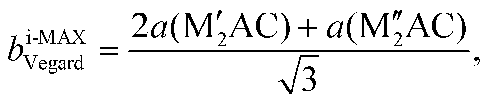 | (5) |
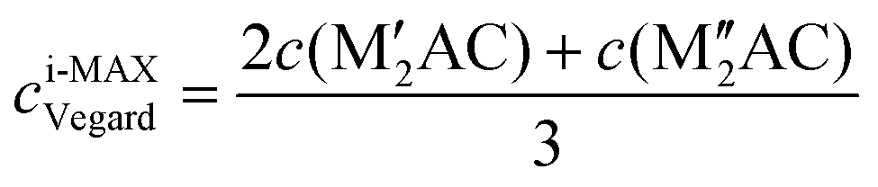 | (6) |
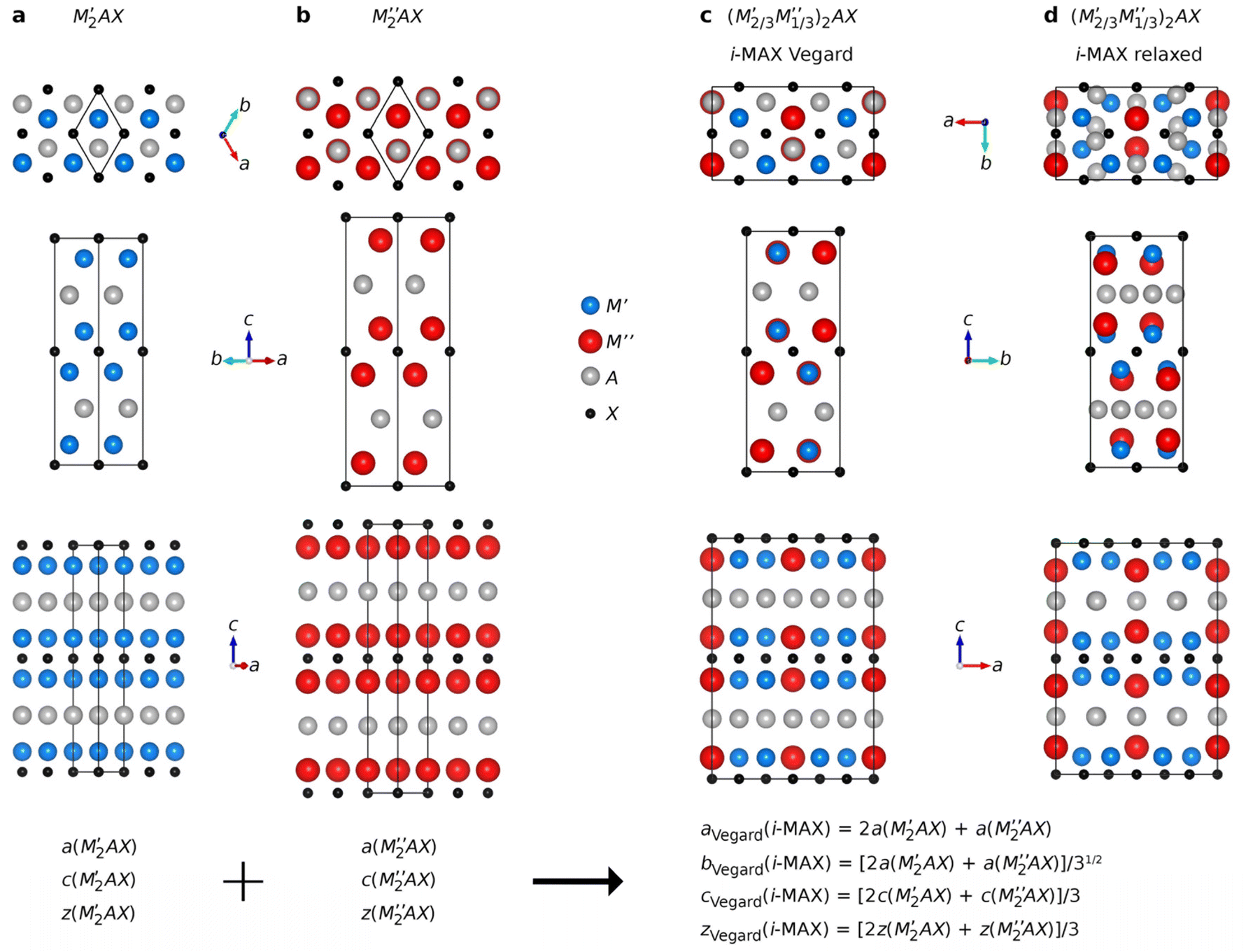 | ||
| Fig. 1 Schematic illustration of how to use structural information from two ternary MAX phases, (a) M′2AC and (b) M′′2AC, to create a structure (c) with the i-MAX in-plane chemical order of M′ and M′′, but with a retained underlying MAX phase structure. In (d) the relaxed i-MAX structure is shown to illustrate how the M′′ layer is situated closer to the A-layer and the A-layer is turned into a Kagomé-like structure, diverging from the hexagonal structure of the A-layer in (c). | ||
The internal z coordinate for metal atoms in the cell is generated by
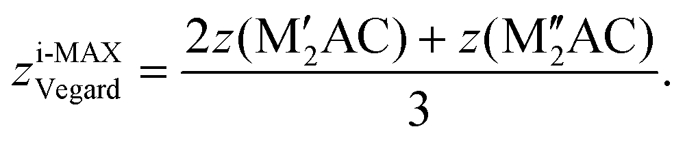 | (7) |
Visualization of atomic structures was done using the VESTA code.77
Results and discussion
Herein, we systematically investigate the thermodynamic stability of MAX phases upon metal alloying considering both chemical order and disorder (solid solution). The results presented are divided into three parts; (i) search for low-energy ordered structures, (ii) high-throughput phase stability screening, and (iii) assessment for the identification of formation rules defining preference for chemical order or solid solution.Search for chemically ordered structures in quaternary MAX phase alloys
For the M2AX phase, two different types of chemical order have been reported to date. The most common is the solid solution of M′ and M′′ on the M-sublattice (see the complete list in ESI Table 1†) for which Ti, V, and Cr are among the most common metals, see e.g. ref. 31, 49 and 78. More recently, chemical in-plane order of M′ and M′′ has been reported,28,33 coined i-MAX (see the complete list in ESI Table 2†), with a 2:1 ratio of M′:M′′, where M′ forms a honeycomb lattice and M′′ a trigonal lattice extended toward the A-layer. Here, the most common combinations include M′ = Mo, Cr, W and M′′ = Sc, Y, with A being Al and Ga.
For quaternary (M′1−xM′′x)2AC MAX phase systems, the compositional phase space is very large even when restricted to metal alloying alone. Here it is justified to critically ask if there are additional chemically ordered structures possible other than the reported i-MAX structure, especially when A is not Al or Ga. We approach this challenging question by starting from the M2AX phase structure, illustrated in Fig. 2g, combined with the alloy theoretic automated toolkit (ATAT) to create about 1500 chemically ordered quaternary candidate structures for different values of x in (M′1−xM′′x)2AC. We initially chose six quaternary systems constituted by A-elements of various size (Cu, Al, and In) combined with M′ + M′′ being Ti + V and Mo + Y. The metal combinations represent systems with small and large differences in the atomic size, motivated by the previous claim that a significant size difference between the two M-elements can facilitate i-MAX formation.33,79 For comparison, we also include solid solutions in our analysis. A schematic illustration of a quaternary solid solution MAX phase is represented in Fig. 2h for the 144-atom supercell generated for x = 1/3. Note that the supercell structures used to model solid solution still possess an initial P63/mmc space group symmetry, despite its non-hexagonal appearance which, as shown in Fig. 2h, is monoclinic-like. This is a result when creating a supercell with optimized correlation functions to model solid solution. For the solid solution phases, we also include contributions from configurational entropy to the Gibbs free energy at a typical synthesis temperature of 2000 K.
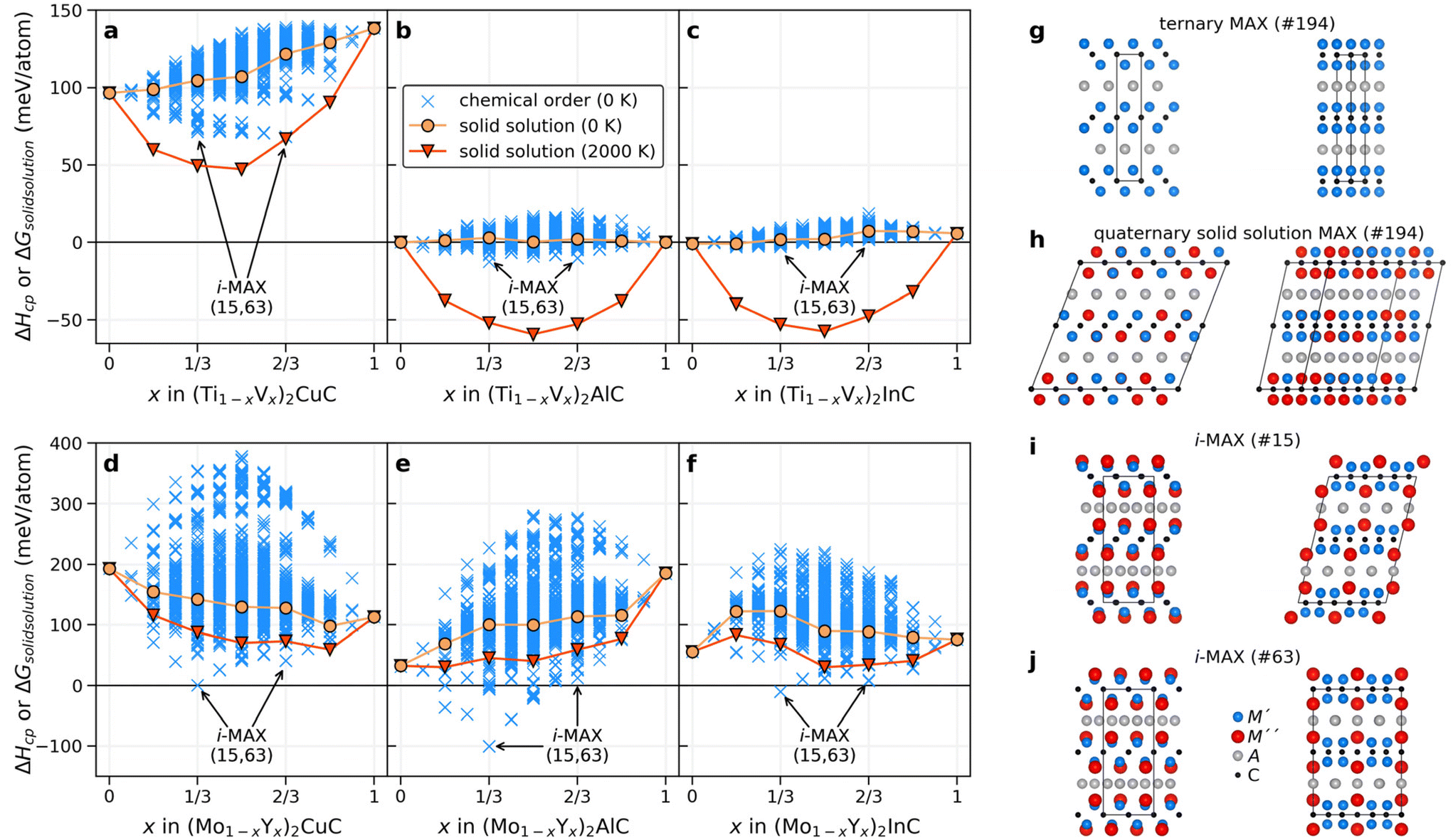 | ||
| Fig. 2 Structural search for chemically ordered structures. Calculated enthalpy of formation ΔHcp for (a–c) (Ti1−xVx)2AC and (d–f) (Mo1−xYx)2AC where A = Cu, Al, and In. Structures with chemical order are shown by crosses (×) and solid solution by filled circles (●). For solid solutions, the entropic contribution at 2000 K has been added to the Gibbs free energy, shown by filled triangles (▼). The formation enthalpy of the i-MAX structures, of both space groups, 15 and 63, are indicated by arrows at x = 1/3 and 2/3 for each quaternary system. Schematic illustrations of (g) the ternary MAX phase along with (h) the quaternary solid solution MAX phase and the i-MAX structure with (i) C2/c and (j) Cmcm space group symmetry, with an M′:M′′ ratio of 2:1. All four structures are shown from two different in-plane views. | ||
Fig. 2a–f show the calculated formation enthalpy for ordered and solid solution candidates for each of the six quaternary systems. Systems with a small difference in the atomic radii between the two M elements, that is (Ti1−xVx)2AC, show a strong preference for solid solution formation (or weak ordering tendencies) at all x values, as concluded from the higher energy of the ordered candidate structures as compared to the solid solution. This is most evident when the largest A-element is In (Fig. 2c). For A = Al and In, a rather small spread in energy is found for the ordered candidates as compared to A = Cu. Note that Cu have a smaller atomic size compared to Al and In.
For systems with a large size difference between the two M elements, (Mo1−xYx)2AC, the spread in ΔHcp is significant for varying x, from 250 meV per atom for In (largest A) to almost 400 meV per atom for Cu (smallest A). In all three systems, the i-MAX structures of both C2/c (#15) and Cmcm (#63) space groups, illustrated in Fig. 2i and j, are identified as the lowest energy structures at x = 1/3 and 2/3. Note that both C2/c and Cmcm are degenerate in energy which can be related to an equivalent local structure within the A-(M′2/3M′′1/3)2C–A layer subunit as discussed in ref. 79 and 80. A closer examination of low-energy candidate structures for x ≠ 1/3 and 2/3 reveals an i-MAX structure with an intermixing of M′ at M′′ sites, and vice versa, in agreement with the results in ref. 81. A detailed comparison of the in-plane ordered i-MAX structure with the original ternary P63/mmc M2AX structure (Fig. 2g) can be found in ref. 33. It should also be noted that if, e.g., chemical order was to be investigated at x = 0.25, 0.50, and 0.75 only in a general (M′2/3M′′1/3)2AX system, a possible low-energy structure such as i-MAX would not have been found.
Thermodynamic stability of quaternary MAX phase alloys
Next, we take advantage of the confirmed ordered i-MAX structures identified in Fig. 2 and conduct an extensive thermodynamic stability screening based on alloying between metals M′ and M′′ (Sc, Y, Ti, Zr, Hf, V, Nb, Ta, Cr, Mo, W, Mn, Fe, Co, and Ni) in combination with A = Al, Ga, In, Si, Ge, Sn, Ni, Cu, Zn, Pd, Ag, Pt, Au, and X = C. We consider systems with M′ ≠ M′′ and M′ or M′′ ≠ A resulting in 2702 unique (M′2/3M′′1/3)2AC compositions.The general screening strategy to retrieve a pool of thermodynamically stable candidates with information related to the preference for order or solid solution is based on a stepwise high-throughput procedure. In this strategy, there are three tiers of selection where candidates are selectively filtered as they go down each tier. In this way, the focus is on the most stable systems for which we also consider the more computationally demanding solid solution MAX phase structures.
The first stability criteria include the evaluation of formation energy ΔEf, i.e., the energy difference of (M′2/3M′′1/3)2AC i-MAX with respect to its constituent atoms in their ground-state structures, and this is shown in Fig. 3a. Only those with ΔEf < 0 pass to the second tier, corresponding to a total of 2210 compositions (81.8%), evidently a majority of the evaluated phases. The second stability criteria include the comparison of the energy difference between (M′2/3M′′1/3)2AC i-MAX and a combination of the identified equilibrium simplex for the two ternary M′2AC and M′′2AC systems. This is shown in Fig. 3b. 528 phases (19.5%) with ΔHcp(ternaries) < 0 are passed to the third tier. We also chose to include 655 phases (24.2%) with 0 ≤ ΔHcp(ternaries) < 60 meV per atom, even though they are found to be not stable, or at best metastable. This is motivated by the possibility that a disordered solid solution may be lower in energy as compared to the i-MAX structure, and a temperature of 2000 K corresponds to a configurational entropy contribution of 55 meV per atom when evaluated at x = 1/3 and 2/3 using eqn (2) and (3). Note that tier 1 could have been excluded by directly applying tier 2. However, the purpose of including tier 1 is to demonstrate that formation energy is a poor stability descriptor considering the transfer of 81.8% to the second tier, eliminating only 18.2% of the initially considered elemental compositions. This can be compared to tier 2 which transfers 1183 phases (43.8%) to tier 3.
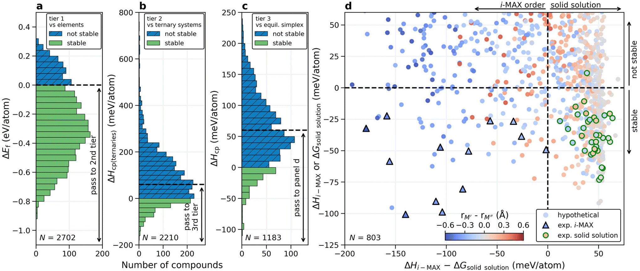 | ||
| Fig. 3 Screening for chemical order and disorder. (a) Calculated formation energy of (M′2/3M′′1/3)2AC i-MAX with respect to constituent elements in their ground state structure, (b) formation enthalpy with respect to the M′2AC and M′′2AC equilibrium simplex, and (c) formation enthalpy with respect to the quaternary equilibrium simplex. (d) Calculated formation enthalpy (i-MAX) or Gibbs free energy of formation at 2000 K (solid solution MAX phase) as a function of the energy difference between the i-MAX and solid solution MAX phase. The coloring represents the atomic size difference between M′ and M′′. Experimentally known i-MAX phases are indicated by triangles (Δ) and solid solution MAX phases by circles (○). | ||
In the third tier, we also consider solid solution for the (M′2/3M′′1/3)2AC composition, and perform a complete stability assessment for each quaternary system. Fig. 3c shows ΔHcp for the identified chemical order (or disorder) of the lowest energy. 189 out of the 1183 compositions are stable, ΔHcp < 0, while 614 compositions are found within 0 ≤ ΔHcp < 60 meV per atom. With these three tiers we have reduced the total number of compositions from 2702 to 803 and it is now feasible to elaborate in more detail on how the calculated stability reflects the experimentally known MAX phases.
Shown in Fig. 3d is a summary of whether chemical order or solid solution is to be preferred for the 803 compositions passing the third tier, as shown in Fig. 3c. Here the calculated stability, represented by the lowest energy out of ΔHi-MAX or ΔGsolid solution, is plotted as a function of the energy difference between chemically ordered i-MAX and disordered MAX, ΔHi-MAX − ΔGsolid solution. Note that ΔGsolid solution represents the Gibbs free energy for the solid solution MAX phases where the contribution from configurational entropy is estimated at 2000 K. This is motivated by synthesis being performed at T > 0 K, typically in the range from 1000 to 1800 °C (1273 to 2073 K) for the MAX phases. The coloring used in Fig. 3d represents the atomic size difference between M′ and M′′ (see ESI Table 3†). All reported synthesized i-MAX phases are marked by triangles and MAX with solid solution of M′ and M′′ by circles.
Thermodynamically stable i-MAX phases encompass 92 unique combinations and are found in the lower left quadrant of Fig. 3d. This includes 13 synthesized i-MAX phases (ESI Table 2†), all composed of metal atoms with an atomic size rM′′ > rM′ by at least 0.2 Å. Stable i-MAX phases are mainly represented by M′ = Sc, V, Cr, Mo, or Mn, M′′ = Sc, Y, or Zr, and A = Al, Ga, or Zn (see Fig. 4), and there are many prospective i-MAX phases remaining to be experimentally realized. A complete list of chemistries for i-MAX phases predicted stable can be found in ESI Table 4.† Not stable or at best metastable i-MAX phases are shown in the upper left quadrant of Fig. 3d.
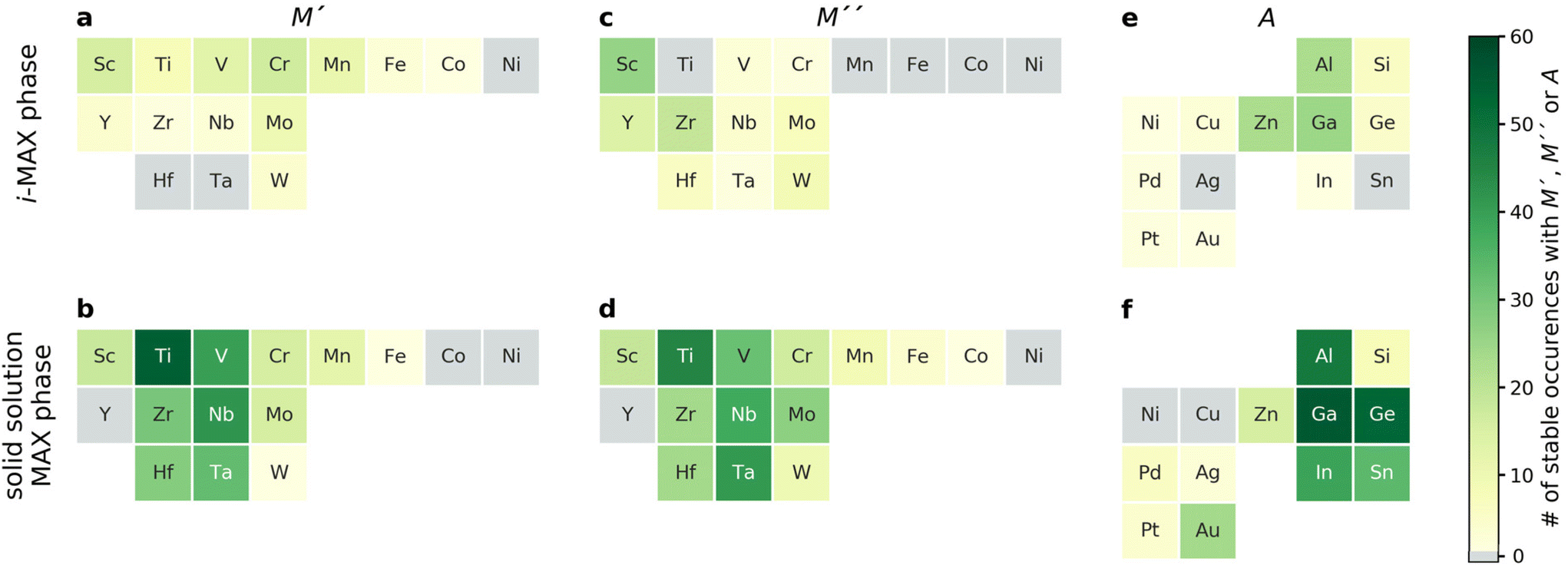 | ||
| Fig. 4 Number of atomic elements in predicted stable i-MAX and solid solution MAX phases. Number of thermodynamically stable phases, with ΔHi-MAX or ΔGsolid solution < 0, for (a and b) M′, (c and d) M′′, and (e and f) A where elements are categorized according to the chemical order/disorder of lowest energy being i-MAX (a, c and e) or solid solution MAX (b, d and f). The number of elemental occurrences is given by the colour bar, from light green (few phases) to dark green (many phases). Grey colour corresponds to an element which is not present in any MAX phase combinations. | ||
All but one of the reported MAX phases with solid solution of M′ and M′′ (ESI Table 1†) are theoretically stable and found in the lower right quadrant of Fig. 3d. Here the atomic size difference of M′ and M′′ fulfills −0.2 Å < rM′ − rM′′ < 0.2 Å. There are more than 200 hypothetical MAX phase solid solutions fulfilling these criteria. These stable phases are mainly represented by traditional M and A MAX phase elements, with M′ and M′′ from groups 4 and 5 (Ti, Zr, Hf, V, Nb, Ta) combined with A from groups 13 and 14 (Al, Ga, In, Ge, Sn), as shown in Fig. 4. A complete list of chemistries for identified stable solid solution MAX phases is found in ESI Table 5,† demonstrating that there are many phases remaining to be discovered experimentally. The upper right quadrant represents metastable solid solution MAX phases including the only experimentally realized solid solution MAX phase not found stable, (Cr0.67Mo0.33)2GeC, with ΔGsolid solution = +12 meV per atom. Here it should be noted that the reported composition in ref. 45 is based on the nominal bulk powder ratio used for the synthesis, without any compositional analysis of the resulting sample, which may introduce a significant error bar to the stated composition of the synthesized MAX phase.
Fig. 3 demonstrates that the stability of synthesized phases is accurately predicted from theory, and that there are many stable phases, ordered and disordered, remaining to be synthesized. However, no explicit information about the MAX phase composition is given in the figure. To resolve this, we choose to display the trends in thermodynamic stability using a heat map representation, where M′ and M′′ are listed on the basis of the metal's periodic group. This is shown in Fig. 5 for A = Al, for the compositions passing the third tier, as shown in Fig. 3c. The background color represents the calculated thermodynamic stability for the chemically ordered/disordered configuration of the lowest energy, with the blue region representing stable phases (ΔHcp or ΔGsolid solution < 0). We also use a symbolic representation to denote the structure of the lowest energy: chemically ordered i-MAX (triangles) and disordered MAX (circles). Fig. 5a depicts the calculated formation enthalpy at 0 K showing that 40 elemental combinations of M′ and M′′ are stable and ordered in the i-MAX structure. None of the solid solution MAX phases are found to be stable at 0 K.
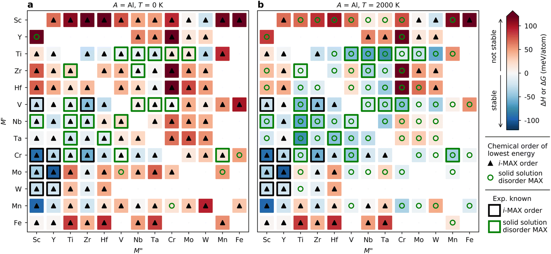 | ||
| Fig. 5 Predicted phase stability for (M′2/3M′′1/3)2AlC alloys. Calculated formation enthalpy ΔH and Gibbs free energy of formation ΔG at (a) 0 K and (b) 2000 K. Symbols represent chemical order of lowest energy at given M′ and M′′ with i-MAX represented by black triangles and solid solution MAX by green circles. Experimentally reported phases are marked with open squares for i-MAX (□) and solid solution MAX (□). | ||
Since the synthesis is performed at T > 0 K, typically in the range from 1000 to 1800 °C (1273 to 2073 K) for MAX phases, the impact of configurational entropy on the free energy of a solid solution (M′0.67M′′0.33)2AC needs to be considered, represented by ΔGsolid solution. The heat map shown in Fig. 5b is constructed by comparing ΔHcp of the chemically ordered i-MAX structure with ΔGsolid solution of the disordered MAX phase solid solution, with colors and symbols used in line with Fig. 5a. At 2000 K, 23 i-MAX phases are found to be both thermodynamically stable with respect to the competing phases, and also stable against the formation of a solid solution MAX at typical synthesis temperatures. This is corroborated by the reported synthesis of nine i-MAX phases, as indicated by the black squares. Moreover, when going from a (0 K) to b (2000 K), the number of stable solid solution MAX phases has increased from 0 to 48. It is important to note that this includes the 20 synthesized MAX phase compositions with solid solution of M′ and M′′, as marked by green squares, see ESI Table 1† for experimentally reported quaternary solid solution MAX phases. Note that neither Co nor Ni belong to a phase found to be stable or close to stable. Similar heat maps for the compositions passing the third tier in Fig. 2c with A ≠ Al (i.e. A = Ga, In, Si, Ge, Sn, Ni, Cu, Zn, Pd, Ag, Pt, and Au) can be found in ESI Fig. 4–15.† All experimentally known MAX phases, in-plane ordered i-MAX phases and solid solutions are found stable, except for the solid solution (Cr0.667Mo0.333)2GeC which is found with ΔGsolid solution = +12 meV per atom (ESI Fig. 7†).
Taking a historical perspective, the first quaternary MAX phases were discovered in the early 1980s, with A = Al, as shown in Fig. 6. The first solid solution MAX with A = In was reported 20 years later in 2002. Discoveries reported in the last 10 years include solid solution MAX phases with the incorporation of new M-elements (Mn) and chemically ordered i-MAX structures. In retrospect, all but one of the synthesized MAX phases are found thermodynamically stable in this work. This lends credibility towards the realization of the many hypothetical phases predicted stable herein, and thus demonstrates avenues for a prospective expansion of MAX compositions.
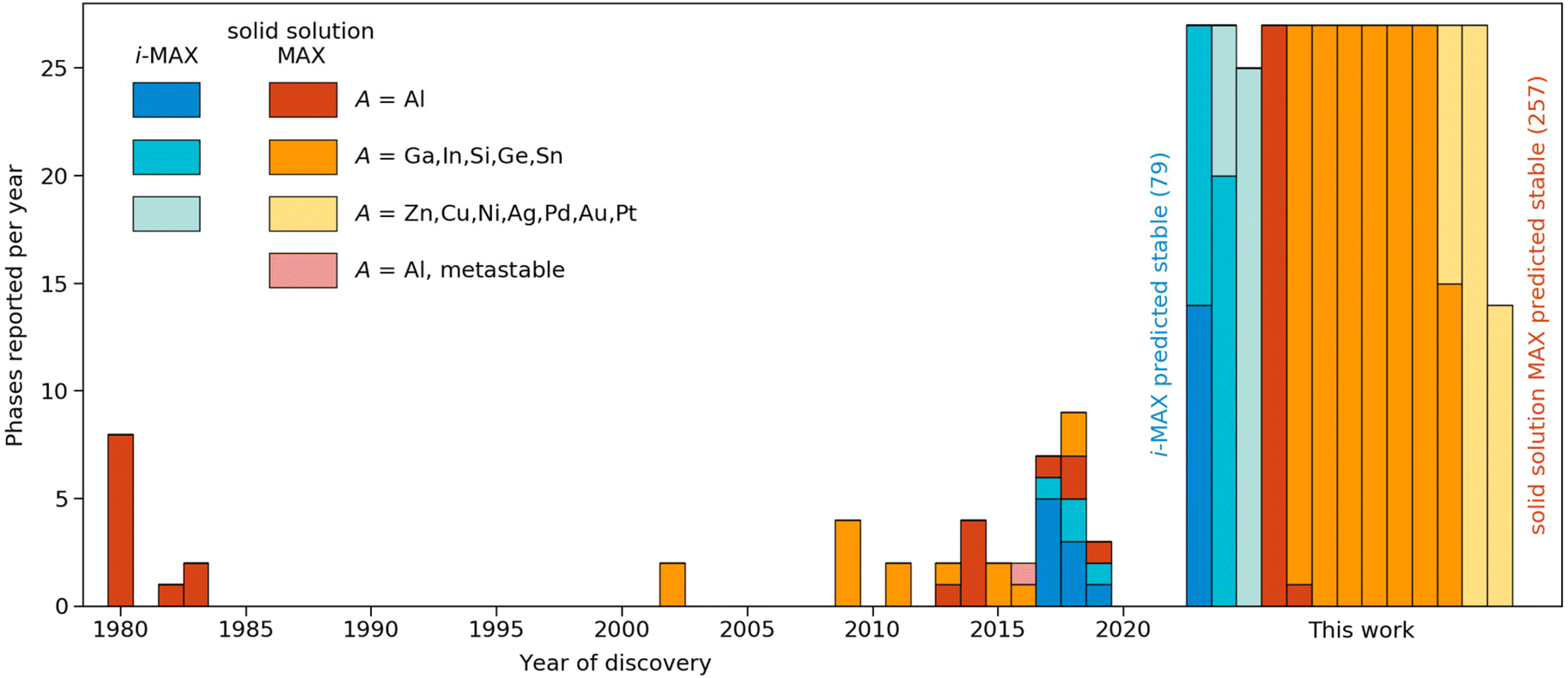 | ||
| Fig. 6 Discovery histogram for experimentally realized and theoretically predicted stable MAX phases formed upon metal alloying. Colours denoting the type of phase (ordered/disordered) and specific A-element. The year of discovery with reference is given in Tables 1 and 2 in the ESI.† | ||
Origin of chemical order and disorder in MAX phases
Understanding why certain metal combinations lead to the formation of chemically ordered i-MAX phases, while others show preference for solid solution, is a fundamental question. In previous works it has been stated that i-MAX formation requires the size difference between M′′ and M′ to be larger than 0.2 Å.33,79 However, this claim was based on a few synthesized and hypothetical i-MAX phases. In this work we considered a large number of compositions spanning known and hypothetical i-MAX phases (in total 2702 unique compositions) which can be used to achieve a deeper insight into when and why order or disorder is expected. We will consider the impact of both size and electronegativity of M′, M′′, and A.We start by comparing how favorable it is to form an i-MAX structure as compared to retaining the ordinary MAX phase structure with M′ and M′′ in the same layer. Here the MAX phase structure, with an i-MAX composition, is constructed using Vegard's law by a linear combination of the structural parameters for the constituent end members, M′2AC and M′′2AC, as specified in eqn (4)–(7). See Fig. 1 for a schematic illustration of how M′2AC and M′′2AC are used to construct this phase composed of i-MAX order and composition while still retaining the MAX phase crystal structure. Note that the calculations of this structure are performed as static, i.e., there is no relaxation of the unit cell structure and internal atomic parameters. ESI Fig. 22† shows that no apparent correlation exists when comparing the lattice parameters a, b and c of the relaxed i-MAX structure and the MAX phase structure generated by using Vegard's law as a function of atomic size difference of M′ and M′′.
Fig. 7a shows the energy difference between a relaxed i-MAX structure and an i-MAX composition in a MAX phase structure, as a function of atomic size difference of M′ and M′′. The coloring represents the atomic radius of the A element where blue represents small atoms, like Si, and red represents large atoms, like In. We find that the i-MAX structure is almost exclusively energetically favored, and increasingly so, with a smaller size of A and larger size difference between M′ and M′′. This is also highly correlated with experimentally known i-MAX phases.
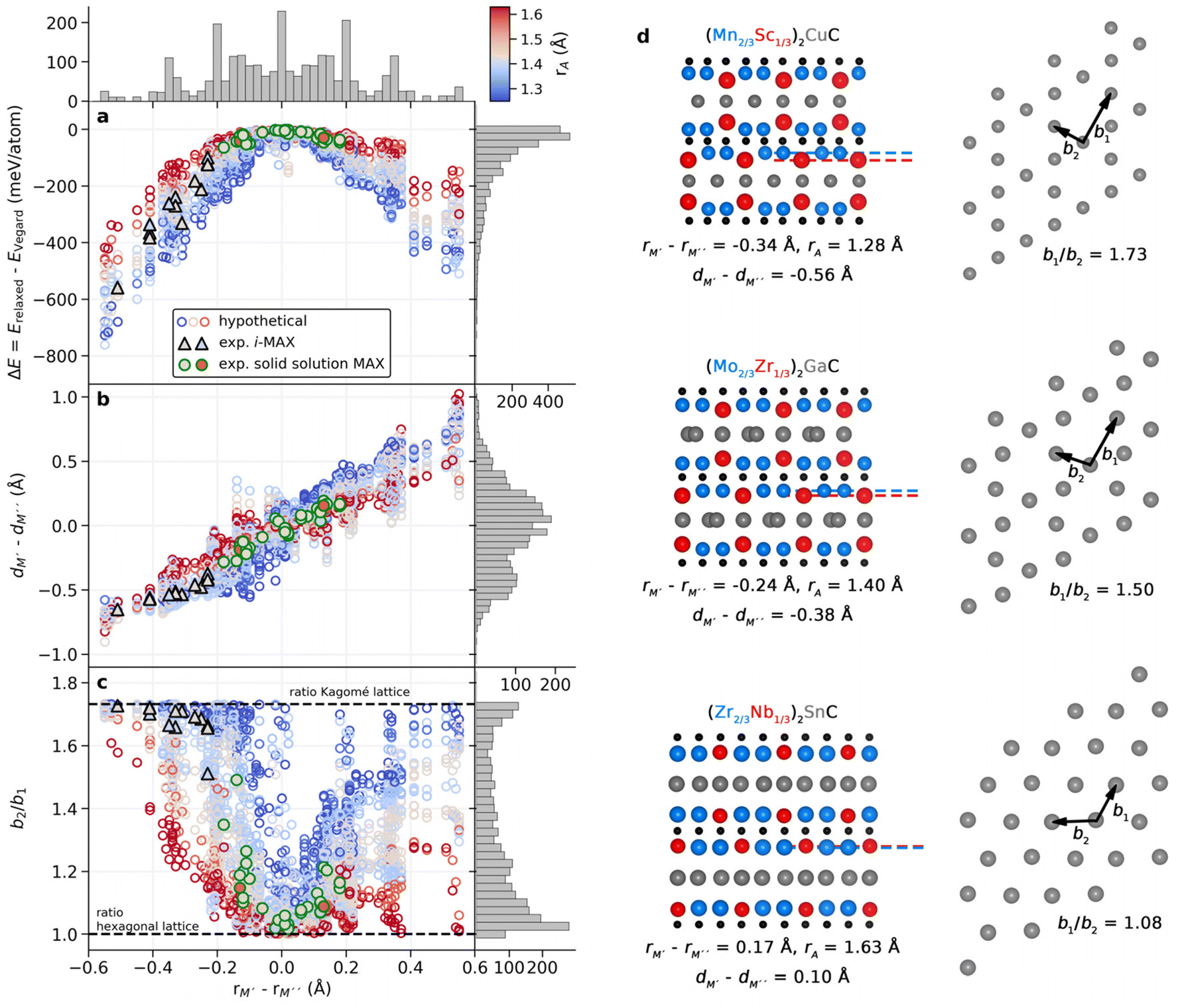 | ||
| Fig. 7 Impact of the atom size on the formation of the i-MAX structure. (a) Calculated energy difference between relaxed i-MAX and MAX phase generated by Vegard's law structure, (b) interlayer distance between M′ and M′′ for relaxed i-MAX, and (c) the ratio of the next-nearest and nearest A–A distances within the A-layer, as a function of atomic size difference of M′ and M′′ for (M′2/3M′′1/3)2AC. Experimentally known i-MAX phases are indicated by black triangles and solid solution MAX phases by green circles. The coloring represents the atomic radius of the A element. Histograms are given for each axis. (d) Representative structures with structural indicators given for various M′, M′′, and A in the side-view (left panel) and for the A-layer in the top view (right panel). For each structure the atomic size difference rM′–rM′′, interlayer distance dM′–dM′′ between M′ and M′′, and size of A are given. For the A-layer, two representative bond distances are indicated, b1 and b2, which are shown in (c) as the b1/b2 ratio. | ||
In Fig. 7b we look at the interlayer distance dM′ − dM′′ between M′ and M′′ layers as a function of the atomic size difference of M′ and M′′. Here dM′ − dM′′ < 0 indicates that M′′ is closer to the A-layer than M,′ and dM′ − dM′′ > 0 indicates that M′ is the closest to the A-layer. There is a clear correlation of M′′ being closer to the A-layer when rM′ < rM′′ and M′ being closer to the A-layer when rM′ > rM′′. Most experimentally known i-MAX phases have dM′ − dM′′ < −0.35 Å. This will, in turn, result in structural changes within the A-layer as compared to the ordinary MAX phase structure.
To demonstrate the change in the A-layer structure for i-MAX phases as compared to the MAX phase we keep track of two different A–A distances, b1 and b2, see schematic illustrations in Fig. 7d, which corresponds to the nearest and next-nearest A–A distance within the A-layer. Fig. 7c shows the ratio of these distances, b2/b1, as a function of atomic size difference of M′ and M′′. A value of 1 corresponds to the hexagonal lattice of A, with b1 = b2 as in the traditional MAX phase, and a value of √3 for an ideal Kagomé lattice of A elements. Most experimentally known i-MAX phases have a b2/b1 ratio close to √3. We find that the smaller(larger) the A atom, the smaller(larger) the difference between M′ and M′′ is required for the M′′ to move closer to the A-layer which, in turn, will affect the A-layer structure. In other words, a small(large) A atom has more(less) space within the layer and can more(less) easily rearrange from a trigonal layer to a Kagomé-like layer. This is also reflected by the steeper(flatter) gain in energy for increasing the size difference of M′ and M′′ in Fig. 7a. Consequently, for small A atoms (blue in Fig. 7), the i-MAX structure is attainable for smaller differences between M′ and M′′, while for large A atoms (red in Fig. 7) the metal size difference needs to be significantly larger to promote i-MAX formation. In the same way, for larger A atoms a solid solution would be less dependent on the metal size difference and thus easier to achieve.
The results shown in Fig. 7 thus demonstrate that the previously stated criterion for i-MAX formation, i.e., a size difference between M′′ and M′ is larger than 0.2 Å,33,79 is partly true. It is valid for systems with A of a similar size, such as Al and Ga. However, for smaller A, the size difference between M′′ and M′ can be less than 0.2 Å, while for larger A, the size difference between M′′ and M′ needs to be larger than 0.2 Å. The results also show that the formation of solid solution MAX phases with a large A is less sensitive to the size difference of M′′ and M′. The impact of the sizes of M′, M′′, and A on the preferred chemical order/disorder is further validated by the difference in energy between i-MAX and solid solution MAX, as shown in ESI Fig. 17 and 18.†
The impact of the electronegativity difference between M′ and M′′ or electronegativity of A does not show the same apparent trends as demonstrated in Fig. 7, see ESI Fig. 19–21.† This observation is further corroborated in ESI Fig. 17 and 18† where the energy difference between i-MAX and solid solution is shown as a function of (i) size and (ii) electronegativity difference of M′ and M′′.
Assessment of the bond strength in stable i-MAX phases
In Fig. 3 we show that 92 i-MAX phases are predicted to be stable (see ESI Table 4†) compared to all competing phases in respective material systems. 13 of these phases have so far been realized experimentally out of which four have been successfully converted into i-MXenes through selective etching of both M′′ = Sc or Y and A = Al.28,34,35,82,83 Theory can be used to assess the 3D to 2D conversion, and to potentially identify new synthesizable i-MXenes among herein predicted stable i-MAX phases. The calculations required for such assessment are beyond the scope of the present paper, but a first insight is given through the analysis of the bond strength.For van der Waals bonded materials, where the interlayer interactions are weak enough for the parent compound to be a good candidate for mechanical exfoliation, theoretical predictions focus on the exfoliation energy as the main descriptor.84,85 This is in contrast to layered materials such as MAX phases which do not possess weak interlayer interaction but stronger metal-covalent interlayer interaction which thus hinders mechanical exfoliation. Instead, chemical exfoliation is used for etching the A-layer.25 In previous work on ternary MAX phases, for example force constant analysis, bond strength analysis, and exfoliation energies have been suggested for judging whether exfoliation into 2D MXene would be possible or not.86 However, since the exfoliation process used for converting MAX into 2D MXene is a complex dynamical process, additional thermodynamic variables need to be considered. Nonetheless, we here choose to focus on the evaluation of the bond strength of M–C and M–A since these are representatives of different interlayer interactions in the MAX phase and thus important when going from MAX to MXene. We choose to include i-MAX phases predicted stable in this work (see the list in ESI Table 4†) with M′ being smaller than M′′ (rM′ < rM′′). Note that i-MAX phases with a magnetic element (i.e., M = Mn, Fe, Co) have been excluded. This gives a total of 55 i-MAX phases. The chemical bonding was quantitatively analyzed using the crystal orbital Hamilton population (COHP) methodology with focus on the integrated COHP (ICOHP) up to the Fermi energy over all the atomic orbital interactions between the atoms forming the bonds. COHP has previously been used for the evaluation of the electronic structure and bonding nature in ternary MAX and quaternary i-MAX phases, see e.g. ref. 33, 79 and 87.
Fig. 8a shows the individual bond strength as a function of bond length of M–C and M–A bonds where we intentionally separate M′ and M′′. We have indicated (M′2/3Sc′′1/3)2AlC and (M′2/3Y′′1/3)2AlC, with M′ = Mo and W, in black and purple, respectively, since these have been successively converted into Mo1.33C and W1.33C i-MXenes. There is a clear correlation indicating increasing bond strength with decreasing bond length, with M–C being stronger than M–A, in line with previous work on ternary MAX phases.86 Furthermore, M′–C is slightly stronger than M′′–C while M′–A and M′′–A have an overall rather similar and low bond strength. Again, note that data shown in Fig. 8a are for individual bonds and hence do not take into account the bonding coordination or the number of interactions which, as will be demonstrated below, do matter.
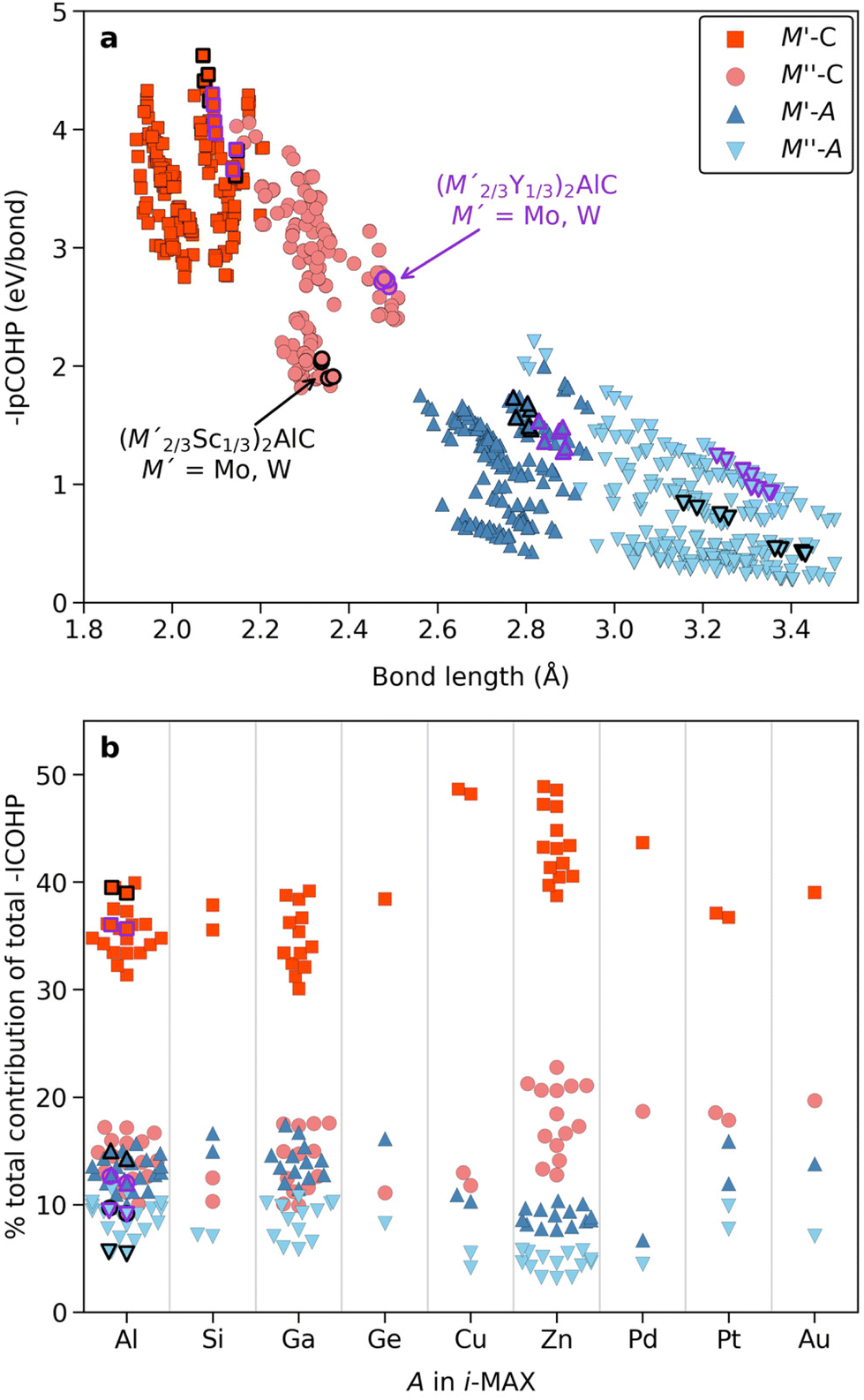 | ||
| Fig. 8 Bond strength for stable i-MAX phases. (a) Individual bond strength quantified by the integrated partial crystal orbital Hamilton population (IpCOHP) up to the Fermi energy for all M–C and M–A interactions as a function of their bond lengths. (b) The contributions, in percentage, of selected interactions with respect to the total net bonding and grouped according to the A-element in the i-MAX phase. Synthesized i-MAX phases which have been successfully converted into i-MXenes, with ordered metal vacancies, are indicated in black and purple depending on M′′ being Sc or Y, respectively. | ||
A solution to this is shown in Fig. 8b for the contribution (in percentage to the total bond strength) of the M′–C, M′′–C, M′–A and M′′–A pairwise interactions, which now incorporate the bonding coordination, with respect to the net (total) integrated bonding within each i-MAX phase. We have grouped the data according to the A-element in the i-MAX phase to highlight that A does matter. Starting with A = Al, for which the four i-MXenes have been realized, the calculations reveal that the M′–C contributes significantly more to the total bonding than M′′–C, M′–A and M′′–A, i.e., M′–C bonds are much stronger. This indicates why selective etching of M′′ and Al in (M′2/3Sc′′1/3)2AlC and (M′2/3Y′′1/3)2AlC is possible when forming M′1.33C i-MXene with M′ = Mo and W. M′′–C, M′–A and M′′–A all showing similar contribution to the total bonding. Qualitatively similar results are also found for A = Si, Ga, and Ge. When it comes to Zn- and Pd-based i-MAX phases we find a slightly different distribution to the total bonding where M–C contributes more than M–A, in particular when comparing M′′–C to M′–A and M′′–A. This indicates a possibility for selective etching of Zn only in (M′2/3M′1/3)2ZnC, under carefully chosen conditions, for conversion into a double-metal (M′2/3M′1/3)2C i-MXene, in line with previous work on (Mo2/3Y1/3)2C i-MXene.34 Realizing a double-metal i-MXene with possibilities of varying both M′ and M′′ would enhance the property tuning possibilities as compared to M′1.33C i-MXenes with ordered vacancies.
Based on the calculated thermodynamical stability for 2702 phases of an (M′2/3M′′1/3)2AC composition, we show that 92 are stable compared to all competing phases and with preference for being chemically ordered in an i-MAX structure. 13 of these phases have so far been realized experimentally. In addition, another 291 compositions are predicted to be stable, though with a preference for solid solution in the traditional MAX phase structure. 33 of these phases have been synthesized. It should be noted that for this family of materials, i.e., for MAX and i-MAX phases, the calculated thermodynamic stability almost exclusively verifies the stability of already synthesized materials. Furthermore, the phase predicted herein as not stable can have the potential of being stabilized under the applied pressure. We believe this is something worth considering in future work.
The agreement between the calculated thermodynamically stable phases with experimental observations lends credibility towards future realization of here predicted stable, but so far hypothetical, i-MAX and solid solution MAX phases. These can, in turn, provide a large playground not only for the exploration of i-MAX and MAX phase properties but, importantly, for transformation into two-dimensional MXene derivatives through selective etching of the A-layer. The latter has been demonstrated to no longer be restricted to etching of Al, but also Si and Ga.25,28,88,89 Tunability of MXene properties could be extended significantly by alloying of the parent MAX phases, as recently demonstrated for Ti, Nb, and V-based solid-solutions with drastically changed electrical conductivity.49 In addition, selective etching of both A and M′′ from i-MAX phases has been demonstrated as a prospective path resulting in MXenes with divacancy ordering28,34,35,81 or with double-metal in-plane order as suggested herein. The many i-MAX and solid solution MAX phases predicted stable herein thus give a glimpse of the future of MAX phase alloys from which many MXenes are to be expected.
Conclusions
In summary, we have shown that adding a fourth element to the family of ternary MAX phases through metal alloying allows for stable and novel elemental combinations in materials not yet synthesized, including both chemically ordered i-MAX phases, (M′2/3M′′1/3)2AC, and solid solution MAX phases, (M′0.67M′′0.33)2AC. Our predictions are reliable as demonstrated by the agreement between computed phase stability and already synthesized materials reported in the literature. The work presented here provides trends in stability as a function of alloying metal elements and A-elements. The preference for order or disorder upon metal alloying in MAX phases is dictated both by the size difference between the alloying metal elements and the atomic size of the A elements. Phases with a large size difference of the alloying elements have a preference for the formation of chemically ordered i-MAX phases, while equal or close to equal size of the alloying elements have a preference for the formation of disordered MAX phases. Additionally, a smaller size of A indicates easier formation of i-MAX, while a larger size of A indicates a preference for solid solution MAX phase formation. Altogether, our results provide a plethora of theoretically predicted stable i-MAX and solid solution MAX phases, 92 and 291, respectively, to be used as guidance for experimental synthesis and in the quest to extend the frontier of the MAX and MXene families.Author contributions
M. D. and J. R. initiated the study and wrote the manuscript. M. D. carried out the first-principles calculations and related analysis.Conflicts of interest
There are no conflicts to declare.Acknowledgements
J. R. acknowledges support from the Knut and Alice Wallenberg (KAW) Foundation for a Fellowship/Scholar Grant and Project funding (KAW 2020.0033), and from the Swedish Foundation for Strategic Research (SSF) for Project Funding (EM16-0004). The calculations were carried out using supercomputer resources provided by the Swedish National Infrastructure for Computing (SNIC) at the High Performance Computing Center North (HPC2N), the National Supercomputer Centre (NSC), and the PDC Center for High Performance Computing partially funded by the Swedish Research Council through grant agreement no. 2018-05973.References
- R. F. Tylecote, A History of Metallurgy, Maney Publishing, for the Institute of Materials, London, 2nd edn, 1992 Search PubMed.
- J. M. Sanchez, F. Ducastelle and D. Gratias, Phys. A, 1984, 128, 334–350 CrossRef.
- C. J. Pickard and R. J. Needs, J. Phys.: Condens. Matter, 2011, 23, 053201 CrossRef PubMed.
- A. R. Oganov and C. W. Glass, J. Phys.: Condens. Matter, 2008, 20, 064210 CrossRef PubMed.
- R. Armiento, B. Kozinsky, G. Hautier, M. Fornari and G. Ceder, Phys. Rev. B: Condens. Matter Mater. Phys., 2014, 89, 134103 CrossRef.
- R. Gautier, X. Zhang, L. Hu, L. Yu, Y. Lin, O. L. SundeTor, D. Chon, K. R. Poeppelmeier and A. Zunger, Nat. Chem., 2015, 7, 308–316 CrossRef CAS PubMed.
- M. Ashton, R. G. Hennig, S. R. Broderick, K. Rajan and S. B. Sinnott, Phys. Rev. B, 2016, 94, 054116 CrossRef.
- A. Talapatra, T. Duong, W. Son, H. Gao, M. Radovic and R. Arróyave, Phys. Rev. B, 2016, 94, 104106 CrossRef.
- C. Nyshadham, C. Oses, J. E. Hansen, I. Takeuchi, S. Curtarolo and G. L. W. Hart, Acta Mater., 2017, 122, 438–447 CrossRef CAS.
- W. Sun, C. J. Bartel, E. Arca, S. R. Bauers, B. Matthews, B. Orvañanos, B.-R. Chen, M. F. Toney, L. T. Schelhas, W. Tumas, J. Tate, A. Zakutayev, S. Lany, A. M. Holder and G. Ceder, Nat. Mater., 2019, 18, 732–739 CrossRef CAS PubMed.
- A. Jain, Y. Shin and K. A. Persson, Nat. Rev. Mater., 2016, 1, 15004 CrossRef CAS.
- M. Dahlqvist, Q. Tao, J. Zhou, J. Palisaitis, P. O. Å. Persson and J. Rosen, J. Am. Chem. Soc., 2020, 142, 18583–18591 CrossRef CAS PubMed.
- A. Jain, S. P. Ong, G. Hautier, W. Chen, W. D. Richards, S. Dacek, S. Cholia, D. Gunter, D. Skinner, G. Ceder and K. A. Persson, APL Mater., 2013, 1, 011002 CrossRef.
- J. E. Saal, S. Kirklin, M. Aykol, B. Meredig and C. Wolverton, JOM, 2013, 65, 1501–1509 CrossRef CAS.
- S. Kirklin, J. E. Saal, B. Meredig, A. Thompson, J. W. Doak, M. Aykol, S. Rühl and C. Wolverton, npj Comput. Mater., 2015, 1, 15010 CrossRef CAS.
- D. Ohmer, I. Opahle, H. K. Singh and H. Zhang, J. Phys.: Condens. Matter, 2019, 31, 405902 CrossRef CAS PubMed.
- D. Ohmer, G. Qiang, I. Opahle, H. K. Singh and H. Zhang, Phys. Rev. Mater., 2019, 3, 053803 CrossRef CAS.
- M. Dahlqvist, B. Alling and J. Rosén, Phys. Rev. B: Condens. Matter Mater. Phys., 2010, 81, 220102 CrossRef.
- J. E. Saal and C. Wolverton, Acta Mater., 2014, 68, 325–338 CrossRef CAS.
- W. Sun, S. T. Dacek, S. P. Ong, G. Hautier, A. Jain, W. D. Richards, A. C. Gamst, K. A. Persson and G. Ceder, Sci. Adv., 2016, 2, e1600225 CrossRef PubMed.
- C. J. Bartel, A. W. Weimer, S. Lany, C. B. Musgrave and A. M. Holder, npj Comput. Mater., 2019, 5, 4 CrossRef.
- W. Jeitschko, H. Nowotny and F. Benesovsky, Monatsh. Chem., 1963, 94, 672–676 CrossRef CAS.
- M. W. Barsoum, Prog. Solid State Chem., 2000, 28, 201–281 CrossRef CAS.
- M. W. Barsoum, MAX Phases, Properties of Machinable Ternary Carbides and Nitrides, Wiley, New York, 2013 Search PubMed.
- M. Naguib, M. Kurtoglu, V. Presser, J. Lu, J. Niu, M. Heon, L. Hultman, Y. Gogotsi and M. W. Barsoum, Adv. Mater., 2011, 23, 4248–4253 CrossRef CAS PubMed.
- A. VahidMohammadi, J. Rosen and Y. Gogotsi, Science, 2021, 372, eabf1581 CrossRef CAS PubMed.
- B. Anasori, M. Dahlqvist, J. Halim, E. J. Moon, J. Lu, B. C. Hosler, E. N. Caspi, S. J. May, L. Hultman, P. Eklund, J. Rosén and M. W. Barsoum, J. Appl. Phys., 2015, 118, 094304 CrossRef.
- Q. Tao, M. Dahlqvist, J. Lu, S. Kota, R. Meshkian, J. Halim, J. Palisaitis, L. Hultman, M. W. Barsoum, P. O. Å. Persson and J. Rosen, Nat. Commun., 2017, 8, 14949 CrossRef PubMed.
- B. Anasori, Y. Xie, M. Beidaghi, J. Lu, B. C. Hosler, L. Hultman, P. R. C. Kent, Y. Gogotsi and M. W. Barsoum, ACS Nano, 2015, 9, 9507–9516 CrossRef CAS PubMed.
- Z. Liu, E. Wu, J. Wang, Y. Qian, H. Xiang, X. Li, Q. Jin, G. Sun, X. Chen, J. Wang and M. Li, Acta Mater., 2014, 73, 186–193 CrossRef CAS.
- E. N. Caspi, P. Chartier, F. Porcher, F. Damay and T. Cabioch, Mater. Res. Lett., 2015, 3, 100–106 CrossRef.
- R. Meshkian, Q. Tao, M. Dahlqvist, J. Lu, L. Hultman and J. Rosen, Acta Mater., 2017, 125, 476–480 CrossRef CAS.
- M. Dahlqvist, J. Lu, R. Meshkian, Q. Tao, L. Hultman and J. Rosen, Sci. Adv., 2017, 3, e1700642 CrossRef PubMed.
- I. Persson, A. E. Ghazaly, Q. Tao, J. Halim, S. Kota, V. Darakchieva, J. Palisaitis, M. W. Barsoum, J. Rosen and P. O. Å. Persson, Small, 2018, 14, 1703676 CrossRef PubMed.
- R. Meshkian, M. Dahlqvist, J. Lu, B. Wickman, J. Halim, J. Thörnberg, Q. Tao, S. Li, S. Intikhab, J. Snyder, M. W. Barsoum, M. Yildizhan, J. Palisaitis, L. Hultman, P. O. Å. Persson and J. Rosen, Adv. Mater., 2018, 30, 1706409 CrossRef PubMed.
- B. Manoun, S. K. Saxena, G. Hug, A. Ganguly, E. N. Hoffman and M. W. Barsoum, J. Appl. Phys., 2007, 101, 113523–113527 CrossRef.
- T. Cabioch, P. Eklund, V. Mauchamp, M. Jaouen and M. W. Barsoum, J. Eur. Ceram. Soc., 2013, 33, 897–904 CrossRef CAS.
- T. Lapauw, B. Tunca, D. Potashnikov, A. Pesach, O. Ozeri, J. Vleugels and K. Lambrinou, Sci. Rep., 2018, 8, 12801 CrossRef PubMed.
- H. Fashandi, M. Dahlqvist, J. Lu, J. Palisaitis, S. I. Simak, I. A. Abrikosov, J. Rosen, L. Hultman, M. Andersson, A. Lloyd Spetz and P. Eklund, Nat. Mater., 2017, 16, 814–818 CrossRef CAS PubMed.
- M. Nechiche, T. Cabioc'h, E. N. Caspi, O. Rivin, A. Hoser, V. Gauthier-Brunet, P. Chartier and S. Dubois, Inorg. Chem., 2017, 56, 14388–14395 CrossRef CAS PubMed.
- Y. Li, J. Lu, M. Li, K. Chang, X. Zha, Y. Zhang, K. Chen, P. O. Å. Persson, L. Hultman, P. Eklund, S. Du, J. S. Francisco, Z. Chai, Z. Huang and Q. Huang, Proc. Natl. Acad. Sci. U. S. A., 2019, 117, 820–825 CrossRef PubMed.
- B. Gou, L. Wang, B. Ye, C. Meng, X. Li, Q. Chen, T. Yang and W. Xu, J. Mater. Sci.: Mater. Electron., 2021, 32, 13081–13088 CrossRef CAS.
- A. S. Ingason, A. Mockute, M. Dahlqvist, F. Magnus, S. Olafsson, U. B. Arnalds, B. Alling, I. A. Abrikosov, B. Hjörvarsson, P. O. Å. Persson and J. Rosen, Phys. Rev. Lett., 2013, 110, 195502 CrossRef CAS PubMed.
- C. Jiang and A. Chroneos, Phys. Chem. Chem. Phys., 2017, 20, 1173–1180 RSC.
- S. Lin, Y. Huang, L. Zu, X. Kan, J. Lin, W. Song, P. Tong, X. Zhu and Y. Sun, J. Alloys Compd., 2016, 680, 452–461 CrossRef CAS.
- M. Naguib, G. W. Bentzel, J. Shah, J. Halim, E. N. Caspi, J. Lu, L. Hultman and M. W. Barsoum, Mater. Res. Lett., 2014, 2, 233–240 CrossRef.
- T. H. Scabarozi, C. Gennaoui, J. Roche, T. Flemming, K. Wittenberger, P. Hann, B. Adamson, A. Rosenfeld, M. W. Barsoum, J. D. Hettinger and S. E. Lofland, Appl. Phys. Lett., 2009, 95, 101907 CrossRef.
- Y. Zhou, F. Meng and J. Zhang, J. Am. Ceram. Soc., 2008, 91, 1357–1360 CrossRef CAS.
- M. Han, K. Maleski, C. E. Shuck, Y. Yang, J. T. Glazar, A. C. Foucher, K. Hantanasirisakul, A. Sarycheva, N. C. Frey, S. J. May, V. B. Shenoy, E. A. Stach and Y. Gogotsi, J. Am. Chem. Soc., 2020, 142, 19110–19118 CrossRef CAS PubMed.
- M. Dahlqvist and J. Rosen, Nanoscale, 2020, 12, 785–794 RSC.
- M. Dahlqvist and J. Rosen, Phys. Chem. Chem. Phys., 2015, 17, 31810–31821 RSC.
- A. Thore, M. Dahlqvist, B. Alling and J. Rosén, Comput. Mater. Sci., 2014, 91, 251–257 CrossRef CAS.
- A. Poulou, T. A. Mellan and M. W. Finnis, Phys. Rev. Mater., 2021, 5, 033608 CrossRef CAS.
- G. Kresse and J. Hafner, Phys. Rev. B: Condens. Matter Mater. Phys., 1993, 47, 558–561 CrossRef CAS PubMed.
- G. Kresse and J. Furthmüller, Comput. Mater. Sci., 1996, 6, 15–50 CrossRef CAS.
- G. Kresse and J. Furthmüller, Phys. Rev. B: Condens. Matter Mater. Phys., 1996, 54, 11169–11186 CrossRef CAS PubMed.
- P. E. Blöchl, Phys. Rev. B: Condens. Matter Mater. Phys., 1994, 50, 17953–17979 CrossRef PubMed.
- G. Kresse and D. Joubert, Phys. Rev. B: Condens. Matter Mater. Phys., 1999, 59, 1758–1775 CrossRef CAS.
- J. P. Perdew, K. Burke and M. Ernzerhof, Phys. Rev. Lett., 1996, 77, 3865–3868 CrossRef CAS PubMed.
- A. Petruhins, M. Dahlqvist, J. Lu, L. Hultman and J. Rosen, Cryst. Growth Des., 2020, 20, 55–61 CrossRef CAS.
- H. J. Monkhorst and J. D. Pack, Phys. Rev. B: Solid State, 1976, 13, 5188–5192 CrossRef.
- R. Dronskowski and P. E. Bloechl, J. Phys. Chem., 1993, 97, 8617–8624 CrossRef CAS.
- V. L. Deringer, A. L. Tchougréeff and R. Dronskowski, J. Phys. Chem. A, 2011, 115, 5461–5466 CrossRef CAS PubMed.
- S. Maintz, V. L. Deringer, A. L. Tchougréeff and R. Dronskowski, J. Comput. Chem., 2013, 34, 2557–2567 CrossRef CAS PubMed.
- R. Nelson, C. Ertural, J. George, V. L. Deringer, G. Hautier and R. Dronskowski, J. Comput. Chem., 2020, 41, 1931–1940 CrossRef CAS PubMed.
- A. van de Walle and G. Ceder, J. Phase Equilib., 2002, 23, 348 CrossRef CAS.
- A. van de Walle, M. Asta and G. Ceder, Calphad, 2002, 26, 539–553 CrossRef CAS.
- A. Zunger, S. H. Wei, L. G. Ferreira and J. E. Bernard, Phys. Rev. Lett., 1990, 65, 353–356 CrossRef CAS PubMed.
- B. Alling, Phys. Rev. B: Condens. Matter Mater. Phys., 2010, 82, 054408 CrossRef.
- A. Manzoor, S. Pandey, D. Chakraborty, S. R. Phillpot and D. S. Aidhy, npj Comput. Mater., 2018, 4, 47 CrossRef.
- M. Griseri, B. Tunca, S. Huang, M. Dahlqvist, J. Rosén, J. Lu, P. O. Å. Persson, L. Popescu, J. Vleugels and K. Lambrinou, J. Eur. Ceram. Soc., 2020, 40, 1829–1838 CrossRef CAS.
- M. Dahlqvist, B. Alling, I. A. Abrikosov and J. Rosén, Phys. Rev. B: Condens. Matter Mater. Phys., 2010, 81, 024111 CrossRef.
- P. Eklund, M. Dahlqvist, O. Tengstrand, L. Hultman, J. Lu, N. Nedfors, U. Jansson and J. Rosén, Phys. Rev. Lett., 2012, 109, 035502 CrossRef PubMed.
- A. S. Ingason, A. Petruhins, M. Dahlqvist, F. Magnus, A. Mockute, B. Alling, L. Hultman, I. A. Abrikosov, P. O. Å. Persson and J. Rosen, Mater. Res. Lett., 2014, 2, 89–93 CrossRef CAS.
- A. Mockute, M. Dahlqvist, J. Emmerlich, L. Hultman, J. M. Schneider, P. O. Å. Persson and J. Rosen, Phys. Rev. B: Condens. Matter Mater. Phys., 2013, 87, 094113 CrossRef.
- A. Mockute, P. O. Å. Persson, F. Magnus, A. S. Ingason, S. Olafsson, L. Hultman and J. Rosen, Phys. Status Solidi RRL, 2014, 8, 420–423 CrossRef CAS.
- K. Momma and F. Izumi, J. Appl. Crystallogr., 2011, 44, 1272–1276 CrossRef CAS.
- J. C. Schuster, H. Nowotny and C. Vaccaro, J. Solid State Chem., 1980, 32, 213–219 CrossRef CAS.
- M. Dahlqvist, A. Petruhins, J. Lu, L. Hultman and J. Rosen, ACS Nano, 2018, 12, 7761–7770 CrossRef CAS PubMed.
- Q. Tao, J. Lu, M. Dahlqvist, A. Mockute, S. Calder, A. Petruhins, R. Meshkian, O. Rivin, D. Potashnikov, E. A. Caspi, H. Shaked, A. Hoser, C. Opagiste, R.-M. Galera, R. Salikhov, U. Wiedwald, C. Ritter, A. R. Wildes, B. Johansson, L. Hultman, M. Farle, M. W. Barsoum and J. Rosen, Chem. Mater., 2019, 31, 2476–2485 CrossRef CAS.
- A. Mockute, Q. Tao, M. Dahlqvist, J. Lu, S. Calder, E. N. Caspi, L. Hultman and J. Rosen, Phys. Rev. Mater., 2019, 3, 113607 CrossRef CAS.
- R. Meshkian, H. Lind, J. Halim, A. El Ghazaly, J. Thörnberg, Q. Tao, M. Dahlqvist, J. Palisaitis, P. O. Å. Persson and J. Rosen, ACS Appl. Nano Mater., 2019, 2, 6209–6219 CrossRef CAS.
- J. Halim, A. S. Etman, A. Elsukova, P. Polcik, J. Palisaitis, M. W. Barsoum, P. Persson and J. Rosen, Nanoscale, 2020, 13, 311–319 RSC.
- S. Haastrup, M. Strange, M. Pandey, T. Deilmann, P. S. Schmidt, N. F. Hinsche, M. N. Gjerding, D. Torelli, P. M. Larsen, A. C. Riis-Jensen, J. Gath, K. W. Jacobsen, J. J. Mortensen, T. Olsen and K. S. Thygesen, 2D Mater., 2018, 5, 042002 CrossRef CAS.
- N. Mounet, M. Gibertini, P. Schwaller, D. Campi, A. Merkys, A. Marrazzo, T. Sohier, I. E. Castelli, A. Cepellotti, G. Pizzi and N. Marzari, Nat. Nanotechnol., 2018, 13, 246–252 CrossRef CAS PubMed.
- M. Khazaei, A. Ranjbar, K. Esfarjani, D. Bogdanovski, R. Dronskowski and S. Yunoki, Phys. Chem. Chem. Phys., 2018, 20, 8579–8592 RSC.
- J. Emmerlich, D. Music, A. Houben, R. Dronskowski and J. M. Schneider, Phys. Rev. B: Condens. Matter Mater. Phys., 2007, 76, 224111 CrossRef.
- R. Meshkian, L.-Å. Näslund, J. Halim, J. Lu, M. W. Barsoum and J. Rosen, Scr. Mater., 2015, 108, 147–150 CrossRef CAS.
- M. Alhabeb, K. Maleski, T. S. Mathis, A. Sarycheva, C. B. Hatter, S. Uzun, A. Levitt and Y. Gogotsi, Angew. Chem., Int. Ed., 2018, 57, 5444–5448 CrossRef CAS PubMed.
Footnote |
| † Electronic supplementary information (ESI) available. See DOI: https://doi.org/10.1039/d2nr02414d |
| This journal is © The Royal Society of Chemistry 2022 |