DOI:
10.1039/D2NA00295G
(Paper)
Nanoscale Adv., 2022,
4, 4131-4137
Capillary-force-driven self-assembly of carbon nanotubes: from ab initio calculations to modeling of self-assembly†
Received
10th May 2022
, Accepted 22nd August 2022
First published on 5th September 2022
Abstract
In elasto-capillary driven self-assembly of arrays of carbon nanotubes (CNTs) different factors play a role, from the mechanical properties of CNTs to the array geometry. In this work, we provide a multi-scale investigation where we first use density functional theory (DFT) to predict fully ab initio relevant mechanical properties such as Young's modulus, Poisson's ratio, and surface energy. To the best of our knowledge, we are the first to report DFT calculations of the surface energy of CNTs. Then, we feed the computed DFT parameters into a model for capillary-force-driven self-assembly of CNTs. By doing so, we are able to derive and predict cross-correlation between material parameters and array architecture.
1 Introduction
The rational design of micro-/nano-scaled material architectures has recently attracted huge interest as a means to engineer their physical properties. For instance, vertically aligned nanowires (NWs) modulate the optical properties of surfaces because their geometry (diameter, height, pitch) can tailor light confinement and absorption. The consequent enhancement of light harvesting is greatly demanded in photovoltaic applications.1 Arrays of carbon nanotubes (CNTs) allow to build highly-dense 3D integrated circuit architectures. The unprecedented increase in connectivity between different functional layers (e.g., sensing, storing, processing)2 is ideally suited to be exploited in data-intensive technologies like Internet-of-Things (IoT). For all the implementations mentioned above and others, the preservation of the vertical direction during processing of densely-packed arrays of 1D nano-structures is fundamental. However, different fabrication steps may deflect such a desired direction. The exposure to an electron beam, for instance, during characterization through scanning electron microscope, has been reported to bend semiconductor NWs with subsequent formation of NW bundles.3–6 Procedures involving wet etching or cleaning also result in reshaping of the vertical arrangement of NWs7–9 and CNTs. In all these cases, a drying step occurs where capillary menisci between adjacent nano-pillars induce lateral forces that may bring these in contact10,11 and eventually assemble together.
Although self-assembly could have a detrimental impact, its purposeful exploitation can also drive the fabrication of aggressively scaled devices. More specifically, self-assembly stands for a large family of bio-inspired strategies, where components organize autonomously into desired patterns or structures with no human intervention.12–15 The concept originated from the chemistry of molecular assemblies mediated by intermolecular bonds to build up supramolecular systems,16 and it has subsequently broadened its meaning to indicate programmed aggregation of non-molecular parts whose size ranges from nano to macroscopic scale. Indeed, the current extreme shrinkage of the operative regime in various technological fields can be severely hindered by material and engineering limitations at such scales, especially when the fabrication of non-planar 3D structures is involved. Thus, new paradigms such as self-assembly may become a game-changer to enable 3D small scale manufacturing.12
A key aspect of both avoiding undesirable sticking effects and, on the contrary, harnessing them to build smart architectures and/or devices is the ability to engineer and control such effects. In particular, the elasto-capillary driven self-assembly of arrays of 1D nano-structures is a multi-faceted phenomenon where many different factors play a role: (1) the mechanical properties of the involved nano-structures, (2) the geometry of the array (inter-distance, aspect-ratio), (3) the evaporation rate and the surface tension of the fluid in which the nano-scaled beams are immersed. Although a wealth of literature exists concerning the mechanism of clustering in arrays of 1D nano-structures, usually its analysis is mainly based on the elasticity theory alone,10,11,17,18 whereas the material properties are commonly taken from experimental literature. A multi-scale investigation able to integrate a rigorous calculation of mechanical properties into the established theoretical modeling of the phenomenon is still as yet missing. This is the more important when dealing with clustering of 1D nano-structures, where the techniques for experimental characterization of mechanical properties are still under development and the measured values are often prone to rather large experimental errors. Thus, in this work, we use density functional theory (DFT) to predict fully ab initio the relevant mechanical properties of CNTs, such as Young's modulus, Poisson's ratio, and surface energy. We also investigate the impact of both diameter and chirality on such properties. Then, we avail of such physics-based parameters to carry out a theoretical analysis of the self-organization of CNT arrays induced by capillary forces.
CNTs are on the forefront among 1D nano-structures for ground-breaking nano-technological implementations.19–21 CNT field-effect transistors promise to improve the energy efficiency of current communication systems, due to their high charge carrier mobility, linearity, current carrying capability and low noise.22 The good thermal conductivity of CNTs is beneficial for the fabrication of low power consumption sensors.23–25 Overall, their exceptional electronic, optical, thermal, and mechanical properties make CNTs an ideal choice for flexible and printed electronics.26 In particular, CNTs have demonstrated excellent suitability as active layers in energy autonomous wearable sensors27–30 for control of health risk factors and achievement of lifelong health monitoring. A way to improve the signal-to-noise ratio is to fabricate devices based on CNT ensembles. In such a case, the alignment of CNTs affects their performance. Additionally, novel applications can be achieved by engineering the 3D organization of CNTs structures obtained using capillary aggregation methods.
Our paper is organized as follows: the first section is dedicated to predicting the relevant mechanical parameters of CNTs via DFT simulations; here, we describe the details of our simulations and present the results. Then, in the following section, the mechanism of capillary-force-driven self-assembly of CNTs is expressed through a simple model. The previously computed DFT parameters (Young's modulus, Poisson's ratio, and surface energy) are fed into such a model. Finally, inferences regarding the occurrence of self-assembly are consequently derived.
2
Ab initio simulations on Young's modulus, Poisson's ratio, and surface energy of CNTs
2.1 Simulation details
In this work, we considered CNTs with different radii (from ∼2.5 Å up to ∼10 Å) and with different chiralities, i.e., armchair and zigzag. Atomistic simulations were carried out in the framework of density functional theory (DFT) with QuantumATK atomic-scale modelling software.31,32 We performed the calculations in vacuum using the Perdew–Burke–Ernzerhof (PBE) exchange–correlation functional,33 and to model core electrons, we used norm-conserving pseudopotentials from the PseudoDojo library.34 The LCAO approach was used throughout this work with a density-mesh cut-off of 150 Ry and the QuantumATK-optimized Medium basis set. We used a k-point mesh defined by a 1 × 1 × 11 Monkhorst–Pack (MP) grid.35 When performing geometry optimizations, we enforced a 0.01 eV Å−1 threshold for the residual atomic forces. Finally, to avoid any spurious interaction between periodic images, we included a vacuum padding of 10 Å along the x and y directions. See Fig. 1 for a representative example of one of our CNT models.
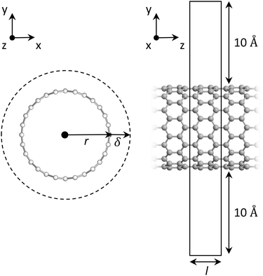 |
| | Fig. 1 Optimized structure of a representative zigzag (14,0)CNT, front and side views. On the left, r and δ are the radius and the thickness of the nanotube, respectively. On the right, l is the tube length. The unit cell is also shown, highlighting the vacuum padding around the tube. | |
To simulate strain (ε) along the tube (that is, along the z direction), we stretched the simulation cell and the C atoms contained therein at steps of 1%, and between −5% (compressive strain) and +5% (tensile strain). Then, at each step, we carried out a full geometry optimization in order to relax the position of the C atoms in the presence of strain, and we computed the total energy of the system. The mechanical properties of CNTs used throughout this study were extracted fully ab initio, i.e., without the use of any empirical parameter. The Young's modulus (Y) can be computed via the following equation:
| |  | (1) |
which is the second order derivative of the energy/strain curve at
ε = 0.
36 In this equation,
E is the total energy of the system as computed by DFT and
V0 is the equilibrium volume defined as:
where
r0 and
l0 are the radius and the length of the CNT, respectively, at
ε = 0.
δ is the thickness of the tube. As per convention,
37 we chose
δ = 3.35 Å, which is the interlayer distance in graphite as obtained by our DFT simulations. We computed the Poisson's ratio (
ν) as:
| |  | (3) |
where
rε is the radius of the CNT at each percentage of strain.
36 Finally, we extracted the surface energy per unit area (
γ) by adapting the equation discussed by Medasani
et al.:
38,39| |  | (4) |
where
Ecohgraphene is the cohesive energy of graphene,
n is the number of atoms,
EbCNT is the total binding energy of the CNT, and the denominator is the surface area of the CNT.
2.2 Results and discussion
We computed the mechanical properties of CNTs as a function of both radius and chirality (armchair and zigzag). The results are shown in both Table 1 and Fig. 2.
Table 1 Computed mechanical parameters of the CNT structures considered in this work by DFT. d is the tube diameter, Y the Young's modulus, ν is the Poisson's ratio, and γ is the surface energy
| Structure |
d (Å) |
Y (TPa) |
ν
|
γ (J m−2) |
| (6,0) |
4.84 |
0.948 |
0.165 |
2.042 |
| (8,0) |
6.38 |
0.992 |
0.157 |
1.167 |
| (10,0) |
7.92 |
1.004 |
0.126 |
0.744 |
| (14,0) |
11.06 |
1.012 |
0.163 |
0.377 |
| (16,0) |
12.61 |
1.015 |
0.127 |
0.287 |
| (20,0) |
15.76 |
1.015 |
0.152 |
0.182 |
| (26,0) |
20.46 |
1.015 |
0.147 |
0.106 |
| (4,4) |
5.54 |
0.973 |
0.144 |
1.568 |
| (5,5) |
6.88 |
0.985 |
0.145 |
1.003 |
| (6,6) |
8.23 |
0.997 |
0.146 |
0.694 |
| (7,7) |
9.59 |
1.016 |
0.146 |
0.509 |
| (8,8) |
10.94 |
1.009 |
0.146 |
0.386 |
| (12,12) |
16.37 |
1.016 |
0.147 |
0.167 |
| (15,15) |
20.45 |
1.019 |
0.152 |
0.105 |
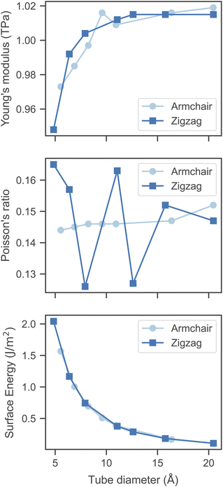 |
| | Fig. 2 Mechanical properties of the CNT structures considered in this work (armchair and zigzag) as a function of the tube diameter, as obtained via DFT simulations. | |
First, our simulations predict Y to increase with respect to the tube diameter and to converge to ∼1.02 TPa when d ≥ 12–13 Å. However, we note that even at smaller diameters, Y is still reasonably close to 1 TPa. Our computed value of Y compares well with both experimental and theoretical data, although it is worth pointing out that there exists a rather large variability reported in the literature. Regarding experimental data, such variability is due to the employed measurement technique and the quality of the CNT samples, as it is known that defects can have a non-negligible effect. On the other hand, in theoretical models, the variability is primarily due to the CNT thickness (as previously mentioned, here we use δ = 3.35 Å). Overall, typical values of Y for single-wall CNTs oscillate around 1 TPa.40,41 Chirality does not seem to have a major effect on Y, although the increasing trend with respect to the tube diameter is somewhat less smooth in armchair CNTs. Overall, our results suggest the stiffness of CNTs to slightly increase with respect to their diameter.
The Poisson's ratio (ν) is the second parameter that we have computed. Interestingly, we observed that the chirality of the tube appears to have some effect on this quantity. As can be seen from Fig. 2, armchair CNTs possess roughly the same value of ν (0.14–0.15) regardless of the tube diameter, whereas, in zigzag CNTs, such a value oscillates between 0.125 and 0.165. However, for d > 15 Å, we observe that for both zigzag and armchair CNTs, the Poisson's ratio converges to ∼0.15. Once again, we point out that our results are consistent with published experimental data, in which ν was found to range between 0.149 and 0.340.42
Finally, we computed the surface energy (γ) of CNTs, which, to the best of our knowledge, has never been previously computed via DFT simulations for this class of materials. As per its definition, surface energy is the energy required to create one unit of surface area. In this work, we computed γ by considering graphene as the reference structure from which CNTs are derived (see Simulation details). Therefore, γ can be seen as a measure of the excess energy induced by the curvature of the C–C bonds in the structure of CNTs. Indeed, our results predict a decrease of γ with respect to the diameter of the tubes, regardless of the chirality. For d ≈ 5 Å, we found a rather high value of ∼2.0 J m−2, which reduces to ∼0.1 J m−2 for diameters larger than 2 nm. It is worth noting that there exists a large variability in the experimental value of the surface energy of CNTs, although on average γ = 0.26 J m−2, larger and smaller values have also been reported.43 Nevertheless, our results appear to be within the accepted range of values. The decreasing trend of γ with respect to the CNTs diameters can be easily explained by the amount of strain induced by the curvature to the sp2 C–C bonds, which should normally be planar. Smaller diameters would lead to a larger distortion of the planarity of C–C bonds and, thus, increase the surface energy.
3 Elastocapillary self-assembly of carbon nanotube arrays
The self-assembly of CNTs mediated by elasto-capillary forces is due to the combination of two different mechanisms (Fig. 3). First, (A) the process of bending the CNTs to favor the contact between their surfaces (Fig. 3a). To this aim, the CNTs are immersed in a liquid, whose evaporation induces their bending, provided that the capillary forces acting during the drying step defeat the elastic forces that would reset them back to the original vertical alignment. Second, (B) the process of CNT bundling (Fig. 3b). This occurs if the adhesion forces acting between the touching surfaces of CNTs are larger than the elastic forces that would tend to set them apart. In the following, we model the elasto-capillary self-assembly of CNTs by considering the simplest possible bundled unit composed of two CNTs. For simplicity's sake, we assume that both CNTs have the same geometry and physical properties. It has been demonstrated10 that the lateral forces resulting from capillary menisci interaction are those responsible for the clustering of micro-sized pillars after liquid evaporation. The capillary force between two cylindrical structures (FC) when they are partially immersed in a liquid can be estimated through Kralchevsky's asymptotic solution11 as:| |  | (5) |
where γliq is the liquid surface tension, θ is the equilibrium contact angle between the cylindrical surface and the liquid, R is the cylinder's radius, and 2x is the inter-distance between axes of two structures (Fig. 3a). Regarding the elastic force that would restore each pillar to the original straight position, this can be estimated from the Euler–Bernoulli elementary beam theory44 as the elastic force deflecting a beam clamped at one end, of height h, such that the free end is deflected of w:| |  | (6) |
where E is the pillar's Young modulus and I is its area moment of inertia.
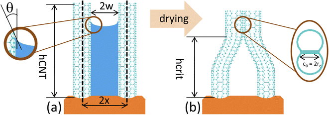 |
| | Fig. 3 (a) Capillary meniscus between two CNTs, the distance between whose axes being 2x. In the inset is magnified the interface vapor/liquid close to the CNT surface, where θ is the contact angle. (b) Lateral collapsing between two adjacent CNTs. | |
We determine FC from eqn (5) for all the CNTs considered, whose radii RCNT are listed in Table 1. We use values of w ranging from 1 to 100 nm. We consider water as the liquid catalyzing the coalescence of CNTs, as frequently reported in literature. Consequently, we use θ equal to 86°45 and γH2O = 72 mN m−1. Fig. 4 shows the behavior of calculated FCvs. w for CNT armchair (4,4) (Fig. 4a; green dotted line) and for CNT armchair (15,15) (Fig. 4b; green dashed line). w is x − Rext, for Rext = RCNT + δ being the external radius of CNT, where δ = 0.335 nm is CNT thickness. The magnitude of FC decreases from 8.36 to 0.124 pN for CNT armchair (4,4), and from 31.8 to 0.6 pN for CNT armchair (15,15), within the probed interval of w. We determine Fel from eqn (6) for all the CNTs, where the corresponding Young's moduli are reported in Table 1. We calculate ICNT as the area moment of inertia of a tube, π × (Rext4 − Rint4)/4, with Rint = RCNT. Fig. 4 shows calculated Felvs. w for different values of CNT height hCNT (from 24 nm to 10 μm). By comparing FC and Fel values, we can assess when capillary forces are stronger than elastic forces. In case of CNTs armchair (4,4) (Fig. 4a) and hCNT equal or smaller than 24 nm, Fel is larger than FC for all probed w values. This means that CNTs are not brought into contact by capillary forces. For hCNT larger than 24 nm and smaller than 500 nm, it exists a threshold value of w above which FC becomes smaller than Fel. Finally, for CNTs taller than 500 nm capillary forces are stronger than elastic forces for all considered w values. The same analysis is qualitatively applicable to other armchair CNTs (results of armchair (15,15) are shown in Fig. 4b) and to zigzag CNTs (Fig. ESI1 of the ESI†).
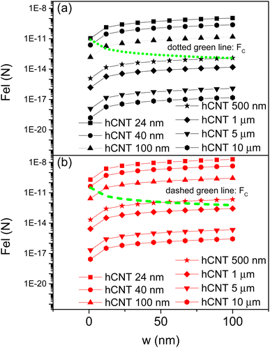 |
| | Fig. 4 Behavior with w of FC from eqn (5) (green lines) and of Fel from eqn (6) (symbols), for (a) armchair (4,4) CNT and (b) armchair (15,15) CNT. | |
Once the conditions for capillary-forces-driven contact of CNTs are established, we also need to assess when the adhesion forces between their surfaces are such to keep them self-assembled. In this respect, we avail of a theoretical model obtained studying the contact behavior of fibrillar interfaces.17,46 Such model has been validated against experimental results for a variety of material interfaces, like arrays of poly(dimethylsiloxane) fibrils17 and gallium arsenide nanowires.3 It is important to note that fibrillar interfaces are intensively investigated to mimic the efficiency of adhesiveness of some natural contact surfaces, for example, the ones of lizards. These interfaces are simply modeled as arrays of pillars (called fibrils) extruding from a substrate. The surfaces of two next-neighbor pillars may stick together, once they are brought to touch each other, due to the influence of van der Waals forces. In this case, the elastic strain energy Ub of the system is concentrated into the noncontact region of length H, which is deformed by the bending (Fig. 3b). The increase of H by a small amount dH implies a consequent strain energy variation of (9EIw2) × dH/H4. If the system is in equilibrium, then it must be equal to the work dW necessary to shrink the contact area. For cylindrical-shaped pillars, the contact radius rc is smaller than cylinder's radius. Also, some elastic deformation occurs near the contact region17 (inset of Fig. 3b). JKR theory18 allows to calculate the equilibrium contact width c0 = 2rc, and thus the energy to separate the two surfaces is determined to be (2γsupc0 − Uc) × dH, where Uc is the elastic energy stored into the deformed region of contact17 and γsup is the surface energy. c0 and Uc are17 as follows:
| |  | (7) |
| |  | (8) |
respectively, for
E* =
E/(1 −
ν2),
ν being the Poisson's ratio. The consideration of energy balancing yields a criterion of critical height for lateral collapse that reads as:
| |  | (9) |
where CNTs bundle if their height is larger than
hcrit. It is noteworthy to observe that
hcrit increases monotonically with
w. Then, a stable bundling is obtained with taller and taller CNTs for arrays with larger and larger inter-distance between CNTs.
Fig. 5 shows
hcrit as determined from
eqn (9) for all armchair CNTs considered, plotted against
w. It can be seen that
hcrit ranges from 5.7 to 57 nm for CNT armchair (4,4), up to from 25 to 255 nm for CNT armchair (15,15). The ranges in which CNT self-assembly is predicted to occur can be assessed by comparison between
Fig. 4 and
5. Thus, in the case of CNT armchair (4,4), for
hCNT below
hA = 24 nm, capillary-force-driven self-assembly does not occur, given that capillary forces are not able to overcome elastic forces. For
hCNT above
hA and below
hB = 500 nm, capillary forces are able to bring CNTs into contact only for
w below a threshold
wth, which depends on
hCNT. In this latter case,
hCNT results to be above
hcrit, thus, the CNTs brought into contact form a bundle. For
hCNT above
hB the capillary-force-driven bundling of CNTs occurs for every value of
w, and the adhesion forces are always able to keep the CNT bundle stable. The above discussion can be repeated for the other armchair (and zigzag) CNTs, where
RCNT modulates the value of
hA and
hB: for example,
hA = 40 nm for CNT armchair (15,15).
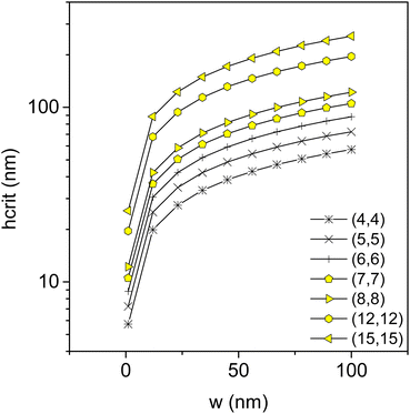 |
| | Fig. 5 Critical height hcrit of lateral collapse by eqn (9), from armchair (4,4) CNT to armchair (15,15) CNT. | |
4 Conclusions
In this work, we show a rigorous approach integrating ab initio calculation of CNT mechanical properties into theoretical modeling of capillary-force-driven self-assembly of CNTs, with the purpose of providing guidelines to exploit this phenomenon. We use DFT to predict Young's modulus, Poisson's ratio, and surface energy of CNTs. We investigate the impact of both diameter and chirality on such properties. We find that (1) Young's modulus increases and (2) surface energy decreases with respect to CNT diameter. To the best of our knowledge, we are the first to report DFT calculations of CNT surface energy. Then, we feed the relevant DFT parameters into a model for capillary-force-driven self-assembly of CNTs. We find that there exists height values hA and hB such that (A) for hCNT < hA capillary-force-driven self-assembly does not occur, (B) for hA < hCNT < hB capillary forces bend CNTs into contact only for w below threshold values wth, and (C) for hCNT > hB the capillary-force-driven bundling of CNTs occurs for every value of w. Finally, we find that such values hA, hB depend on RCNT.
Author contributions
SC and GB conceived the study concept and designed the simulations. GB performed DFT simulations and analyzed the data. SC performed elastic theory calculations and evaluated and interpreted the data. SC and GB drafted the manuscript. ATS critically revised the manuscript. ATS supervised the study. The manuscript has been read and approved by all authors.
Conflicts of interest
There are no conflicts to declare.
Acknowledgements
This project has received funding from the European Union's Horizon 2020 Research and Innovation Programme, EU H2020 SmartVista (https://www.smartvista.eu), grant agreement no. 825114.
References
- W. Chen and P. R. i Cabarrocas, Nanotechnology, 2019, 30, 194002 CrossRef CAS PubMed.
- M. M. Shulaker, G. Hills, R. S. Park, R. T. Howe, K. Saraswat, H.-S. P. Wong and S. Mitra, Nature, 2017, 547, 74–78 CrossRef CAS PubMed.
- S. Carapezzi, G. Priante, V. Grillo, L. Montès, S. Rubini and A. Cavallini, ACS Nano, 2014, 8, 8932–8941 CrossRef CAS PubMed.
- N. Senthilnathan and T. P. Radhakrishnan, Chem. Mater., 2020, 32, 8567–8575 CrossRef CAS.
- L. A. Bitzer, C. Speich, D. Schäfer, D. Erni, W. Prost, F. J. Tegude, N. Benson and R. Schmechel, J. Appl. Phys., 2016, 119, 145101 CrossRef.
- V. M. Kaganer, S. Fernández-Garrido, P. Dogan, K. K. Sabelfeld and O. Brandt, Nano Lett., 2016, 16, 3717–3725 CrossRef CAS PubMed.
- S. Carapezzi and A. Cavallini, Beilstein J. Nanotechnol., 2019, 10, 2094–2102 CrossRef CAS PubMed.
- T. Ghosh, E.-C. Fritz, D. Balakrishnan, Z. Zhang, N. Vrancken, U. Anand, H. Zhang, N. D. Loh, X. Xu, F. Holsteyns, C. A. Nijhuis and U. Mirsaidov, ACS Appl. Mater. Interfaces, 2022, 14, 5537–5544 CrossRef CAS PubMed.
- N. Vrancken, T. Ghosh, U. Anand, Z. Aabdin, S. W. Chee, Z. Baraissov, H. Terryn, S. D. Gendt, Z. Tao, X. Xu, F. Holsteyns and U. Mirsaidov, J. Phys. Chem. Lett., 2020, 11, 2751–2758 CrossRef CAS PubMed.
- D. Chandra and S. Yang, Langmuir, 2009, 25, 10430–10434 CrossRef CAS PubMed.
- P. Kralchevsky, V. Paunov, I. Ivanov and K. Nagayama, J. Colloid Interface Sci., 1992, 151, 79–94 CrossRef.
- K. S. Kwok, Q. Huang, M. Mastrangeli and D. H. Gracias, Adv. Mater. Interfaces, 2020, 7, 1901677 CrossRef.
- M. De Volder and A. J. Hart, Angew. Chem., Int. Ed., 2013, 52, 2412–2425 CrossRef CAS PubMed.
- K. J. M. Bishop, C. E. Wilmer, S. Soh and B. A. Grzybowski, Small, 2009, 5, 1600–1630 CrossRef CAS PubMed.
- G. M. Whitesides and B. Grzybowski, Science, 2002, 295, 2418–2421 CrossRef CAS PubMed.
- J.-M. Lehn, Science, 1993, 260, 1762–1763 CrossRef CAS PubMed.
- N. J. Glassmaker, A. Jagota, C.-Y. Hui and J. Kim, J. R. Soc. Interface, 2004, 1, 23–33 CrossRef CAS PubMed.
- C. Y. Hui, Y. Y. Lin, J. M. Baney and A. Jagota, J. Adhes. Sci. Technol., 2000, 14, 1297–1319 CrossRef CAS.
- Y. Che, H. Chen, H. Gui, J. Liu, B. liu and C. Zhou, Semicond. Sci. Technol., 2014, 29, 073001 CrossRef CAS.
- M. F. L. D. Volder, S. H. Tawfick, R. H. Baughman and A. J. Hart, Science, 2013, 339, 535–539 CrossRef PubMed.
- G. Boschetto, S. Carapezzi and A. Todri-Sanial, IEEE Open J. Nanotechnol., 2021, 2, 120–128 Search PubMed.
- M. Hartmann, J. Tittmann-Otto, S. Böttger, G. Heldt, M. Claus, S. E. Schulz, M. Schröter and S. Hermann, ACS Appl. Mater. Interfaces, 2020, 12, 27461–27466 CrossRef CAS PubMed.
- K. Chikkadi, M. Muoth, V. Maiwald, C. Roman and C. Hierold, Appl. Phys. Lett., 2013, 103, 223109 CrossRef.
- K. Chikkadi, M. Muoth, C. Roman, M. Haluska and C. Hierold, Beilstein J. Nanotechnol., 2014, 5, 2179–2191 CrossRef PubMed.
- S. Carapezzi, S. Reggiani, E. Gnani and A. Gnudi, IEEE Trans. Electron Devices, 2020, 67, 4682–4686 CAS.
- A. Kamyshny and S. Magdassi, Chem. Soc. Rev., 2019, 48, 1712–1740 RSC.
- A. S. Dahiya, J. Thireau, J. Boudaden, S. Lal, U. Gulzar, Y. Zhang, T. Gil, N. Azemard, P. Ramm, T. Kiessling, C. O'Murchu, F. Sebelius, J. Tilly, C. Glynn, S. Geary, C. O'Dwyer, K. M. Razeeb, A. Lacampagne, B. Charlot and A. Todri-Sanial, J. Electrochem. Soc., 2019, 167, 037516 CrossRef.
- A. S. Dahiya, T. Gil, J. Thireau, N. Azemard, A. Lacampagne, B. Charlot and A. Todri-Sanial, Adv. Electron. Mater., 2020, 6, 2000547 CrossRef CAS.
-
R. R. Pandey, J. Liang, D. Cakiroglu, B. Charlot and A. Todri-Sanial, Electrochemical Glucose Sensor Using Single-Wall Carbon Nanotube Field Effect Transistor, 2020, https://arxiv.org/abs/2006.12973 Search PubMed.
-
G. Boschetto, T. Xu, M. Yehya, J. Thireau, A. Lacampagne, B. Charlot, T. Gil and A. Todri-Sanial, 2021 IEEE International Conference on Flexible and Printable Sensors and Systems (FLEPS), 2021, pp. 1–4 Search PubMed.
- S. Smidstrup, T. Markussen, P. Vancraeyveld, J. Wellendorff, J. Schneider, T. Gunst, B. Verstichel, D. Stradi, P. A. Khomyakov, U. G. Vej-Hansen, M.-E. Lee, S. T. Chill, F. Rasmussen, G. Penazzi, F. Corsetti, A. Ojanperä, K. Jensen, M. L. N. Palsgaard, U. Martinez, A. Blom, M. Brandbyge and K. Stokbro, J. Phys.: Condens. Matter, 2020, 32, 015901 CrossRef CAS PubMed.
-
QuantumATK Version S-2021.06, Synopsys QuantumATK, https://www.synopsys.com/silicon/quantumatk.html, last accessed, April 25, 2022 Search PubMed.
- J. P. Perdew, K. Burke and M. Ernzerhof, Phys. Rev. Lett., 1996, 77, 3865–3868 CrossRef CAS PubMed.
- M. J. van Setten, M. Giantomassi, E. Bousquet, M. J. Verstraete, D. R. Hamann, X. Gonze and G.-M. Rignanese, Comput. Phys. Commun., 2018, 226, 39–54 CrossRef CAS.
- H. J. Monkhorst and J. D. Pack, Phys. Rev. B: Solid State, 1976, 13, 5188–5192 CrossRef.
- E. Hernández, C. Goze, P. Bernier and A. Rubio, Phys. Rev. Lett., 1998, 80, 4502 CrossRef.
- J. P. Lu, Phys. Rev. Lett., 1997, 79, 1297 CrossRef CAS.
- B. Medasani, Y. H. Park and I. Vasiliev, Phys. Rev. B: Condens. Matter Mater. Phys., 2007, 75, 235436 CrossRef.
- B. Medasani and I. Vasiliev, Surf. Sci., 2009, 603, 2042–2046 CrossRef CAS.
- A. Krishnan, E. Dujardin, T. W. Ebbesen, P. N. Yianilos and M. M. J. Treacy, Phys. Rev. B: Condens. Matter Mater. Phys., 1998, 58, 14013 CrossRef CAS.
- R. S. Ruoff, D. Qian and W. K. Liu, C. R. Phys., 2003, 4, 993–1008 CrossRef CAS.
- Z.-C. Tu and Z.-C. Ou-Yang, Phys. Rev. B: Condens. Matter Mater. Phys., 2002, 65, 233407 CrossRef.
- M. R. Roenbeck, X. Wei, A. M. Beese, M. Naraghi, A. Furmanchuk, J. T. Paci, G. C. Schatz and H. D. Espinosa, ACS Nano, 2014, 4, 124–138 CrossRef PubMed.
-
R. C. Hibbeler, Mechanics of Materials, Prentice-Hall, Englewood Cliffs, NJ, 3rd edn, 1997 Search PubMed.
- H. Liu, J. Zhai and L. Jiang, Soft Matter, 2006, 2, 811–821 RSC.
- A. Jagota and C.-Y. Hui, Mater. Sci. Eng., R, 2011, 72, 253–292 Search PubMed.
|
| This journal is © The Royal Society of Chemistry 2022 |
Click here to see how this site uses Cookies. View our privacy policy here.  Open Access Article
 *,
Gabriele
Boschetto‡
 and
Aida
Todri-Sanial
 *
*


