
 Open Access Article
 This Open Access Article is licensed under a
 Creative Commons Attribution 3.0 Unported Licence
Freeze casting of porous monolithic composites for hydrogen storage†
George M.
Neville
 a,
Rajan
Jagpal
b,
Joseph
Paul-Taylor
a,
Mi
Tian‡
c,
Andrew D.
Burrows
a,
Chris R.
Bowen
ab and
Timothy J.
Mays
*ac
a,
Rajan
Jagpal
b,
Joseph
Paul-Taylor
a,
Mi
Tian‡
c,
Andrew D.
Burrows
a,
Chris R.
Bowen
ab and
Timothy J.
Mays
*ac
aCentre for Sustainable and Circular Technologies, Department of Chemistry, University of Bath, Bath, BA2 7AY, UK. E-mail: G.M.Neville@bath.ac.uk; J.Paul-Taylor@bath.ac.uk; A.D.Burrows@bath.ac.uk; C.R.Bowen@bath.ac.uk; T.J.Mays@bath.ac.uk
bMaterials and Structures Centre, Department of Mechanical Engineering, University of Bath, Bath, BA2 7AY, UK. E-mail: R.Jagpal@bath.ac.uk
cDepartment of Chemical Engineering, University of Bath, BA2 7AY, UK
First published on 18th October 2022
Abstract
Hydrogen storage by adsorption offers operational benefits over energy intensive compression techniques. Incorporating physisorption materials in compression stores could improve hydrogen capacities, reducing the volume or pressure needed for storage vessels. However, such materials are often presented as fine powders and development efforts to date have predominantly focused on improving hydrogen uptake alone. Without due attention to industry-relevant attributes, such as handling, processability, and mechanical properties it is unlikely that these materials will find commercial application. In the paper, the desirable mechanical properties of hydrogen-adsorbent PIM-1 are exploited to yield a series of composite monoliths doped with a high surface area activated carbon, intended to act as pressure vessel inserts. Freeze casting techniques were successfully adapted for use with chloroform, facilitating the production of coherent and controlled three-dimensional geometries. This included the use of an innovative elastomeric mould made by additive manufacture to allow facile adoption, with the ability to vary multiple forming factors in the future. The composite monolith formed exhibited a stiffness of 0.26 GPa, a compressive strength of 6.7 MPa, and an increased BET surface area of 847 m2 g−1 compared to PIM-1 powders, signifying the first steps towards producing hydrogen adsorbents in truly useful monolithic forms.
1. Introduction
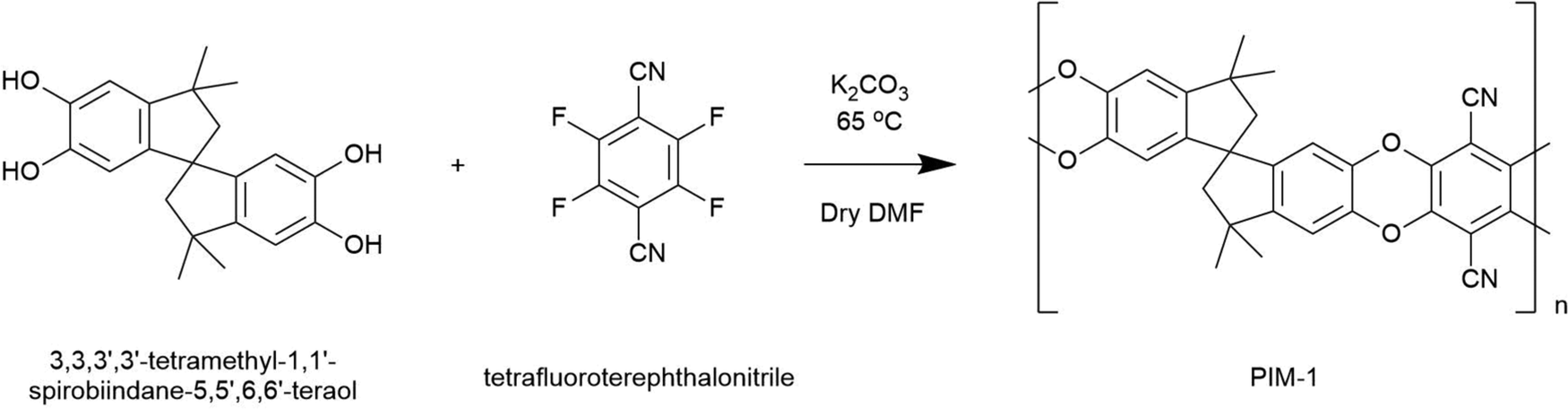
A precursor to all uses of hydrogen is the inevitable requirement to effectively store it. Hydrogen easily supersedes the gravimetric energy density of competing lithium ion batteries, and has a lower heating value over three times that of gasoline (119 MJ kg−1vs. 43 MJ kg−1).1 However, as a gas, hydrogen presents a low volumetric density at atmospheric pressure (0.04 MJ l−1).2 In this regard, the US Department of Energy (DoE) have set targets to guide scientists towards the realisation of viable storage solutions, aimed at facilitating ambitious net-zero objectives such as those set out in UK Hydrogen Strategy.3 The approach appraises systems in full, considerate of operating conditions, cycle lifetime and cost.4 A common place solution for the storage of gas is to use a compression vessel. This consists of a cylinder capped by a hemispherical bulkhead for optimum pressure dissipation. Type I vessels are entirely metallic and are usually used in industrial settings with limited capacity (20–30 MPa). Developments, including leak-resistant liners and composite overwrapped exteriors, have led to the latest generation of Type IV vessels achieving an impressive storage density of 5.68 MJ l−1 at 70 MPa.2,5 However, these systems are still unable to meet DoE targets for light duty vehicles, and further improvements will likely require the discovery of novel storage materials suited to compression vessels.Porous materials for physisorption may offer passive improvement to compression stores, either by working in tandem to improve hydrogen capacities, or by allowing equivalent capacities at less hazardous pressures. Several high surface area materials have now been discovered in this respect, and interest in their application has meant that record hydrogen capacities continue to be reported.6 A range of such material classes are now well established, including metal–organic frameworks (MOFs), porous aromatic frameworks (PAFs), covalent–organic frameworks (COFs), activated carbons, and porous polymers, but their use in commercial applications remains limited. If these materials are to be fully exploited, it is evident that physisorbents must be scrutinised beyond simply their capacity for storage. For example, it is particularly problematic when these materials are presented as fine powders. Notoriously troublesome for industrial use, fine powders present inherent respiratory hazards during handling and are often incompatible with existing process machinery, such as hoppers, due to their poor flowability and tendency to agglomerate.7 Beyond this, to attain properties such as high heat transfer, mechanical strength, and recyclability, various applications will require that materials first be structured into controlled three-dimensional geometries and monoliths. Although some promising forming methods for adsorbents are starting to emerge, including the creation of small monoliths, beads, and hollow fibres8–12 these are highly tailored processes, often reliant on a non-adsorbent matrix for physical integrity, with limited attention paid to downstream geometry control. Here, we present a generic forming approach for monolithic hydrogen adsorbent composites based on the polymer of intrinsic microporosity, PIM-1.
The eponymous porosity of PIM-1 arises from its rotationally constrained spirocentres (Fig. 1), where adjacent planar moieties are too rigid to allow efficient molecular packing, instead generating a matrix of micropores (<2 nm in diameter). Depending on the quality of synthesis, PIM-1 can achieve surface areas between 600–800 m2 g−1, theoretically preserved regardless of the material state, making PIM-1 an excellent candidate for forming development. The polymer is also of specific interest given its solution processability into coherent and flexible thin films that can be cast from chloroform, as in Fig. 1. Such films exhibit desirable mechanical properties, where tensile strength, thermal and temporal stability have all been examined previously.13–15 More recently, to further improve storage abilities, high surface area particulate fillers have been added to PIM-1 during casting, leading to the creation of mixed membrane composites. Fillers have included PAFs,16 MOFs and abundant low-cost activated carbons,17 which can be added in high weight percentages to improve BET surface areas. This means that PIM-1 can be exploited as a generic porous matrix for superior physisorbents, imparting forming capabilities that facilitate application. However, these films are inherently limited by their finite thickness (<1 mm) and consequently, implementation has been narrowly focused on gas separation thus far.9,10,12,18 As a result, novel methods are sought that could generate composite PIM-1 matrixes in the form of larger solid monoliths.
 | ||
| Fig. 1 Schematic of PIM-1 forming challenges highlighting solution processes as a route to composite monoliths. Yellow circle in PIM-1 structure shows rotationally constrained spirocentre. | ||
Unfortunately, PIM-1 presents atypical thermal properties, eluding the majority of forming methods established for plastics. Unlike thermoplastics, that can be formed and reformed freely above the glass transition temperature (Tg), or thermosets, that are crosslinked in situ to achieve coherent parts, the glassy nature of PIM-1 arises from its spirocentres. Originally, differential scanning calorimetry (DSC) experiments revealed only the occurrence of self-crosslinking between 250–400 °C, where the polymer became dark brown or black as a result of triazine ring formation, leading to the films becoming brittle with reduced pore sizes,19 before degradation at 475 °C.15 A full characterisation of this by dynamic mechanical thermal analysis (DMTA), and a discussion of the possible detriment to storage, is detailed in the ESI† (Fig. S4 and S5). One outstanding study radically attempted to instead use extruded PIM-1 fibres to achieve 3D structures through additive manufacture.11 Whilst an impressive demonstration of forming flexibility, limitations were also highlighted, where PIM-1, tetrahydrofuran (THF), and dimethylacetamide ratios first required extensive optimisation for flow and then the appropriate adaptations made as to be compatible with commercial printers. This complexity will predictably raise barriers to industrial adoption. An alternative, less-tailored thermosensitive forming technique is freeze casting.
Freeze casting has been applied to a number of heat-sensitive materials including pharmaceuticals, biomaterials, structural materials and foodstuffs.20 In particular, the process is employed to produce porous solids, reliant on the principle that suspensions or solutes are rejected by the freeze front of the solvent, resulting in what is known as solvent-templated microstructures. The solvent is then sublimed through freeze drying, allowing for its removal without disruption to this microstructure, and if the material is suitable, a solid monolith is formed. Typically, these techniques have been developed in regards to careful unidirectional, or anisotropic freezing, in order to gain fine control of directional microstructures. Alternatively, some isotropic freeze casting methods have also been developed but are less common given that, although sometimes producing radial microstructures, products are predominantly isotropic. One method reported in the literature,21 showed that a 5 by 30 mm cylindrical PIM-1 monolith could be freeze cast with anisotropy from chloroform solutions (0.1–0.2 g mL−1). Promisingly, a BET surface area of 766 m2 g−1 was conserved, however a compressive Young's modulus of 33 kPa was found. This was much below the expected 1 GPa repeatedly reported for dense films in tension, suggesting the monolith was powdery or porous in nature.
Here, we aim to both expand upon this methodology and address the apparent low stiffness of PIM-1 monoliths through rigorous mechanical characterisation. The effect of including an activated carbon filler, namely AX21, is also examined to increase the BET surface area. Through developing an elastomeric mould by additive manufacture, capable of preserving chloroform in a frozen state, it is demonstrated that the process has the potential to be diversely applied to a number of settings with minimal adjustment, helping to realise the potential of physisorbents in the real world.
2. Experimental and process development
2.1 Materials
The monomer tetrafluoroterephthalonitrile (Fluorochem, purity 99%) was received as a light grey powder and recrystallised from hot acetone prior to polymerisation. All other reagents, including the comonomer, 3,3,3′,3′-tetramethyl-1,1′-spirobiindane-5,5′,6,6′-tetraol (Alfa Aesar, purity 97%), the initiator, potassium carbonate (anhydrous, Acros Organics, purity ≥ 99%), and the solvent, N,N-dimethylformamide (DMF) (Acros Organics, purity 99.8%, ≤0.005% water), were used as received without need for further purification. Similarly, other solvents used, including methanol and chloroform (VWR BDH Chemicals), were not purified further. The activated carbon, AX21™ – commercially available as Maxsorb – was originally developed in Kansai, Japan, and is synthesised from a petroleum coke precursor activated by KOH at 973 K.22 This was sourced from Anderson Development Company Inc. (Michigan, US) and did not require further modification before use.2.2 Synthesis of PIM-1
Following the work of Budd et al.,23 PIM-1 was prepared by mixing 3,3,3′,3′-tetramethyl-1,1′-spirobiindane-5,5′,6,6′-tetraol (5.11 g, 14.6 mmol), tetrafluoroterephthalonitrile (3.0 g, 14.7 mmol) and anhydrous K2CO3 (16.59 g, 120 mmol) in 100 mL dry DMF. Mixtures were then degassed with nitrogen and covered with aluminium foil before being heated to 65 °C for 72 h. Here, copolymerisation occurs via aromatic nucleophilic substitution, where K2CO3 deprotonates catechol units facilitating the formation of dioxane linkages between monomers in a 1![[thin space (1/6-em)]](https://www.rsc.org/images/entities/char_2009.gif) :1 ratio. This reactivity imposes a strictly alternating monomer architecture along the copolymer chain; see Scheme 1.
:1 ratio. This reactivity imposes a strictly alternating monomer architecture along the copolymer chain; see Scheme 1.
 | ||
| Scheme 1 Reaction scheme for the polymerisation of PIM-1. | ||
Upon cooling, suspensions were precipitated from 300 mL of water and the yellow powder collected by filtration before extensive washing with water and acetone. Once dry, the powder was then dissolved in a minimal volume of chloroform (typically 80 mL) and reprecipitated dropwise into 900 mL methanol at 0 °C. This procedure was repeated a further three times to ensure sufficient removal of low molecular weight polymer that would otherwise impede film formation. Finally, PIM-1 was retrieved as bright yellow granules that were dried under vacuum at 80 °C for 24 h before use. This typically yielded 4.5 g of product (∼55% conversion). Resulting polymers were subsequently characterised by 1H NMR and gel permeation chromatography (GPC); see Fig. S1 and S2 (ESI†).
2.3 Film casting
Two compositions of precursor chloroform solutions were used for both film and freeze casting. These were pure PIM-1 (100% wt) and a PIM-1:AX21 composite (PIM-1 80% wt, AX21 20% wt) precursor. For brevity, the latter will be referred to simply as the composite.Films were cast from chloroform (10 mL, 40 mg mL−1) by pouring solutions into flat-bottomed glass Petri dishes, which were covered to ensure slow evaporation over 48 h. The resulting films were recovered by the addition of a small volume of water, the surface tension of which gently releases the film from the Petri dish. Films were then dried at 80 °C under vacuum before analysis. Film thickness was determined using a Fowler electronic micrometer with ± 1 μm resolution.
2.4 Freeze casting
In the initial instance, a traditional anisotropic freeze casting methodology was followed. This was adapted from that described by Ahmed et al.,21 whereby 100 mg mL−1 chloroform solutions were directionally frozen from a relatively small, thermally-insulating silicone mould, with a thin thermally-conductive aluminium base, as summarised in Fig. S7 (ESI†). Once frozen, the mould was placed into a freeze dryer to remove the chloroform. However, once under vacuum, it was found that solutions rapidly became liable to uncontrolled boiling, Fig. S6 (ESI†), resulting in foam-like structures filled with voids and defects. These foams were of low mechanical strength and could not be easily handled without damage. The most common solvents used in freeze casting are water (Tm = 0 °C), dioxane (Tm = 12 °C), dimethyl sulfoxide (DMSO, Tm = 19 °C), and camphene (Tm = 51 °C). PIM-1, primarily soluble in chloroform (Tm = −65 °C) and THF (Tm = −108 °C), hence presents a specific challenge when attempting to both slowly freeze solutions but also maintain such low temperatures for prolonged drying periods. Hence, the process was adapted in order to preserve chloroform in a frozen state, as summarised in Fig. 2. | ||
| Fig. 2 Schematic of the isotropic freeze casting method used to produce monoliths. Process steps follow the order as numbered. (1) Fill pre-cooled mould cavity with precursor solution. (2) Place mould onto cold plate and (3) lower into Dewar of liquid nitrogen. (4) Once solution has frozen, transfer mould to thermos flask and (5) place in freeze drier prepared with foil cover. Dry for 24 h before retrieving resultant monoliths. | ||
To facilitate controlled production of PIM-1 and composite monoliths, sublimation was promoted by delaying heat transfer by as much as possible. Although heating by conduction was largely prevented inside the vacuum chamber, structures were also placed inside a vacuum (thermos) flask for additional protection prior to subjecting to full vacuum. To prevent radiative heating, metal foil was placed around all transparent areas of the vacuum chamber. To gain control over monolith sizes and geometries, a bespoke elastomeric mould was designed (Fig. 3a–c) and then manufactured by 3D printing; further details are provided in the following section. To remove any heat remaining in the system, the mould cavity was surrounded by an excess of elastomeric material (Fig. 3b). When cooled, this acts as a cold store of large thermal mass. This final adaptation converted the overall process from anisotropic to isotropic freeze casting in that all sides of the mould had similar conductivities, meaning that microstructures arising from directional freeze fronts were no longer anticipated. To improve the mechanical properties of the monoliths, precursor concentrations were doubled to 200 mg mL−1, expected to reduce porosity and thus increase strength and stiffness.
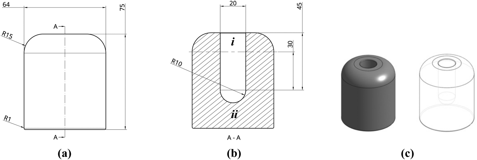 | ||
| Fig. 3 (a and b) Projection drawings of mould (dimensions in mm) and (c) renderings from Onshape. Dimensions are in mm with ‘R’ denoting ‘radius’. To ease discussion, i and ii indicate regions of excess cavity and mould mass, respectively. | ||
The final technique used was documented by video (available in ESI†). Initially, the elastomeric mould was precooled by being placed on the cold plate and lowered into liquid nitrogen (−196 °C). Separately, precursor solutions were stirred for 1 hour to ensure homogeneity. Once the mould had cooled for approximately 30 min, solutions were poured into the cavity, before again lowering the cold plate into the liquid nitrogen to fully solidify (∼15 min). The mould was then transferred to a Virtis SP Scientific freeze dryer under vacuum (<30 Pa) for 24 h. Although equipped with a 188 K condenser, a freeze trap is also recommended between the chamber and vacuum pump to prevent unnecessary damage and the outlet placed inside a fume hood to prevent release of harmful vapours. Monoliths were recovered simply by bending the mould before being further dried in a vacuum oven at 80 °C for 24 h prior to analysis.
2.5 Mould design and manufacture by stereolithography (SLA) printing
A bespoke mould was required in order to produce monoliths of the desired size and geometry. Several considerations for this were needed, including flexibility of design as well as rapid prototyping. Moreover, moulds would need to be made of a sufficiently elastic material to easily retrieve the formed structures after freeze drying and to withstand cyclic cooling cycles in liquid nitrogen. Stereolithography (SLA) 3D printing, using an elastic resin, was chosen to suit these requirements. In contrast to fused deposition modelling (FDM), where deposited layers are not chemically bonded, SLA printing uses laser light to polymerise layers of resin onto a metallic build plate. This allows printing in thermoset polymers, such as the FormLabs proprietary elastic resin used here (methacrylate, acrylate and photoinitiator), to a resolution of 0.1 by 0.3 mm. An ability to print in elastomeric materials is a recent development and allows moulding to take full advantage of the benefits of 3D printing. Compared to traditional silicone mould manufacture, there is no need to create a male mould tool first, and design possibilities are greatly expanded, including the ability to create internal structures.The mould was designed in the cloud CAD software package, Onshape (Fig. 3a and b), and consisted of an extruded cylinder (32 mm radius) with a cavity to be filled with precursor solution. The cavity, a 10 mm radius by 30 mm height cylinder with a 10 mm hemispherical cap, was designed to produce monoliths of the desired geometry, loosely representative of a small hydrogen compression vessel, to a reasonable scale. Above the cavity, a 15 mm excess (i) was included to provide a confined volume to contain any bubbling that could occur. Similarly, an excess of 20 mm of elastomeric material was included between the internal base of the cavity and the base of the mould (ii) to provide a thermal end mass which acts as a heat sink when cooled. As SLA printed parts are printed upside-down, hanging from the build plate (Fig. S8 and S9, ESI†), edges were filleted to remove overhanging weight that could interfere with the printing process. The final design was exported as an .stl file and imported into FormLabs PreForm software. The design was then split into 750 consecutive print layers and uploaded to a Form2 SLA printer. The resulting part was then washed (Form Wash) for 20 min and cured (Form Cure) at 60 °C for 90 min prior to use. Further details of how the mould was processed, post-print, can be found in ESI† S5.
2.6 Static uniaxial compression testing
PIM-1 and composite monoliths were tested in compression to determine mechanical properties, unlike films which are better suited to tensile testing. Standardised tensile testing of PIM-1 films has been detailed elsewhere,14 and hence here, results from dynamic mechanical thermal analysis (DMTA) of films are reported (Fig. S4 and S5, ESI†) to highlight barriers to heat-treatment forming methods. DMTA was not appropriate for monolith compression testing as it was anticipated that monoliths would withstand the maximum loading capacity (∼5 N) without failure, hence invalidating further testing on limited samples. Therefore, monoliths were tested using an Instron 3369 equipped with a 1 kN load cell.For compression testing of monoliths, the ASTM international standard test method for compressive properties of rigid plastics was followed.24 Briefly, this asserts that specimens in the form of a cylinder be machined carefully to ensure smooth, flat parallel surfaces, perpendicular to the long axis, result. In respect of this, monoliths were machined using a MTI STX-202A diamond wire saw at a high RPM (260 RPM) and slow cutting speed (0.1 mm min−1 in the z-direction). Here, samples were mounted to the stage using glass-fibre tape, opposed to the traditional use of hot wax, to prevent damage to the sample exterior. Although it is sometimes recommended that coolant be flowed over the wire, this was also avoided to limit damage and contamination. The samples were then ground using abrasive paper. Ultimate dimensions for the cylindrical compression samples processed were between 17.5–18.0 mm in height, and 11.2–11.9 mm in diameter. Prior to testing, monoliths were set between two 5 mm steel platens, aligned orthogonal to the compression direction. The compressive load was applied at a rate of 1.3 mm min−1. Tests were programed to continue until either a load of 900 N was reached or if there were a sudden decrease in load. Compressive strength, yield strength and Young's modulus are defined here as in the ASTM standard.
2.7 Structural characterisation
Field emission scanning electron microscopy (FESEM) was conducted using a JEOL JSM-6301F field emission microscope at a low accelerating voltage of 5 kV, in secondary electron imaging (SEI) mode. Samples were mounted onto metallic stubs using conductive carbon tape, which in turn were mounted to a viewing stage. Immediately before inspection, samples were sputter coated with a 20 nm conductive chromium film using a Quorum Q15OT S pumped coater. Samples were then stored in vacuo for 24 h to degas before experiments. Fiji ImageJ software25 was used to quantify distances.X-ray computed tomography (XRCT) was primarily used for non-destructive evaluation of internal structures of foams and monoliths after freeze casting. CT inspection was conducted using a Nikon XTH225ST scanner equipped with a tungsten target. Samples inside plastic containers were mounted using low-density foam which may be easily excluded from downstream image analysis. A total of 3141 projections were taken, each composed of an averaged 8 radiographs, allowing for the highest resolution voxel achievable. Data was process using Avizo Fire 9.0 software which allows for both full 3D renderings as well as isolated 2D orthoslices. Colour maps were customised to exclude all but the sample density for visual analysis.
2.8 Surface characterisation
Low pressure isotherms (0.1 MPa) were collected using a Micrometrics 3-Flex, a Sieverts’ type physisorption analyser. Dosage gases used were dependent on the measurement taken: isotherms of N2 adsorption at 77 K were used to determine BET surface area, whereas He at variant temperatures was used to ascertain free space. A known mass of sample (typically 100 mg) was first loaded into tubes fitted with a gasket and seal. Degas procedures were run at 120 °C for 12 h under vacuum, prior to analysis. Heating mantles were then removed and replaced with isothermal jackets, a Dewar of liquid nitrogen placed onto an automated elevator below the samples, and a thermocouple introduced, before isotherm procedures commenced (equilibration interval = 45 s). BET analysis was conducted over a linear isotherm range (p/p0) between 0.05–0.30, following suggestions from Rouquerol et al. in regards to microporous materials.263. Results and discussion
3.1. Forming results
Initial attempts to traditionally freeze cast a precursor solution (100 mg mL−1) from a relatively thin silicone mould (Fig. S7a, ESI†) yielded forms described here as composite foams; see Fig. 4a and b. Examples of pristine PIM-1 foams can be found in Fig. S6 (ESI†). These forms were unsuited to our aims for a number of reasons, most notably their lack of strength and thus inability to be handled without damage. Whilst under vacuum, it was noticed that these solutions rapidly became liable to uncontrolled boiling, Fig. S6a and b, suspected to have induced the mechanically weak and void-filled structures. Indeed, inspection by CT, as seen in Fig. 5a and b, finds that internal wall thicknesses (∼140 μm; Table 1) are not dissimilar to those of comparable films (40 mg mL−1), despite being cast from more concentrated solutions (200 mg mL−1).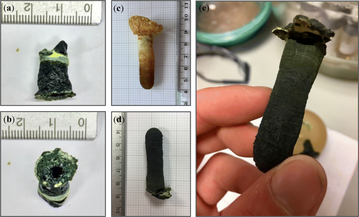 | ||
| Fig. 4 Visual forming results for (a and b) composite foam, (c) PIM-1 and (d) composite monolith. (e) Monoliths were of sufficient integrity to be readily handled without inducing structural damage. | ||
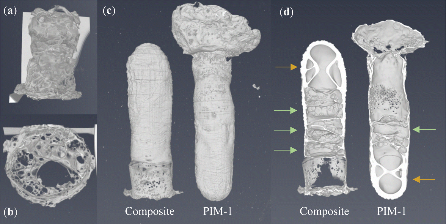 | ||
| Fig. 5 XRCT renderings of (a) composite foam exterior and (b) cross section. Both PIM-1 and composite monolith (c) exteriors and (d) cross sections. Arrows indicate repeated hour glass (yellow) and planar (green) void geometries believed to arise from convection in a hemisphere during freezing. | ||
| Sample | Thickness (μm) | Density (g cm−3) | Porosity fraction (ε)a |
|---|---|---|---|
a Calculated from  where ε is porosity, ρ is calculated density and ρ(bulk) is the bulk density of PIM-1 (0.94 g cm−1).18
b Mean film thicknesses determined using a micrometer. Hence, when used to calculate density, error can be carried (95% C.I.). Density of other structures approximated from a cylinder, hence error unknown.
c Mean wall thicknesses measured from cross-sectional CT analysis. where ε is porosity, ρ is calculated density and ρ(bulk) is the bulk density of PIM-1 (0.94 g cm−1).18
b Mean film thicknesses determined using a micrometer. Hence, when used to calculate density, error can be carried (95% C.I.). Density of other structures approximated from a cylinder, hence error unknown.
c Mean wall thicknesses measured from cross-sectional CT analysis.
|
|||
| PIM-1 Film | 90 ± 20b | 0.22 ± 0.04 | 0.76 ± 0.04 |
| PIM-1:AX21 Film | 231 ± 16b | 0.15 ± 0.01 | 0.84 ± 0.01 |
| PIM-1 Foam | 145c | 0.20 | 0.79 |
| PIM-1:AX21 Foam | 143c | 0.13 | 0.86 |
| PIM-1 Monolith | 1540c | 0.39 | 0.59 |
| PIM-1:AX21 Monolith | 1988c | 0.51 | 0.46 |
Moreover, it appears the melting of chloroform has allowed the AX21 filler to settle to the base of the structure (Fig. 4b), as is seen in films of the same composition.17 The foams also appeared hollow, exhibiting both extensive macro-scale porosity but also an unobstructed path between either end of the structure. Hence, these foams may find interest in low pressure drop applications.
Following adaptions to the method, as described in Section 2.4, the resulting PIM-1 and composite structures, referred to here as monoliths, were of improved integrity and could be readily handled; see Fig. 4c–e. Several features indicate that chloroform had been preserved in a frozen state, including the repeatability of both external and internal structures (Fig. 5c and d), as well as the comparatively increased wall thicknesses (>1.5 mm) and reduced porosity (see Table 1), suggestive of property changes to the material. Although precursor concentrations were increased compared to foams, monoliths cast from comparable solutions in the literature have not achieved such integrity.21 Likewise, although adaptions were made to the freeze drying equipment used, such as the use of a vacuum (thermos) flask and foil, it can be assumed that this had only a minor effect upon heat transfer in comparison to the vacuum. The most prominent difference between procedures was the use of an innovative SLA-printed elastomeric mould, designed with a large thermal mass to act as a cold store.
Evidence from the structures suggests that this is what allowed monoliths to remain frozen during freeze drying. For example, the thickest walls were found at the hemispherical end of the monoliths (Fig. 5c and d), located within the centre of the mould (Fig. 3c) where the greatest thermal protection was expected. Here, colours are darker (Fig. 4c–e), indicative of increased density, and get lighter towards the free end of the monolith, where evaporation by boiling is evident from the ballooning of monoliths at this terminus. Interestingly, internal structures appear most repeatable at the hemispherical end also. Here, hourglass structures appear within the ends of both monoliths (Fig. 5d, indicated by orange arrows) as well as perpendicular, planar voids (green arrows) just above this area. It is believed that this arises from a coupling between convection currents in the precursor solution and the mould geometry during freezing; a schematic is available in Fig. S10 (ESI†). This is not dissimilar to that seen in hemispherical convection models,27 where warm solution rises and excludes a central void, before cooling as it descends the sides of the sphere. The fact these structures are present within monoliths once dry indicates that these sections must have remained frozen for the duration of casting.
SLA-printing was successful in that this allowed an elastomeric mould to be manufactured that could withstand cyclic cooling in liquid nitrogen. The design of the mould confined monoliths to the desired geometry in a sufficiently repeatable manner and could readily be altered in the future for rapid prototyping. However, the monoliths produced were thinner than the mould cavity (∼1 cm vs. 2 cm), due to compression of the mould at low temperatures. Although this was unexpected, and hence not accounted for during design, future experiments may wish to exploit this fact to optimise the forming process. Interestingly, examination of the external faces of both the PIM-1 monolith and PIM-1:AX21 composite monolith under SEM, reveals crisscross patterns of repeating 0.3 by 0.1 mm dimensions; see Fig. 6. This appears to correlate to the resolution of the SLA printing laser, and indeed, inspection of the mould surface finds this pattern at the interface of cured polymer layers. Hence, patterns were likely imprinted onto monoliths during contraction of the mould, highlighting the potential for repeatable geometry control to sub-mm scale.
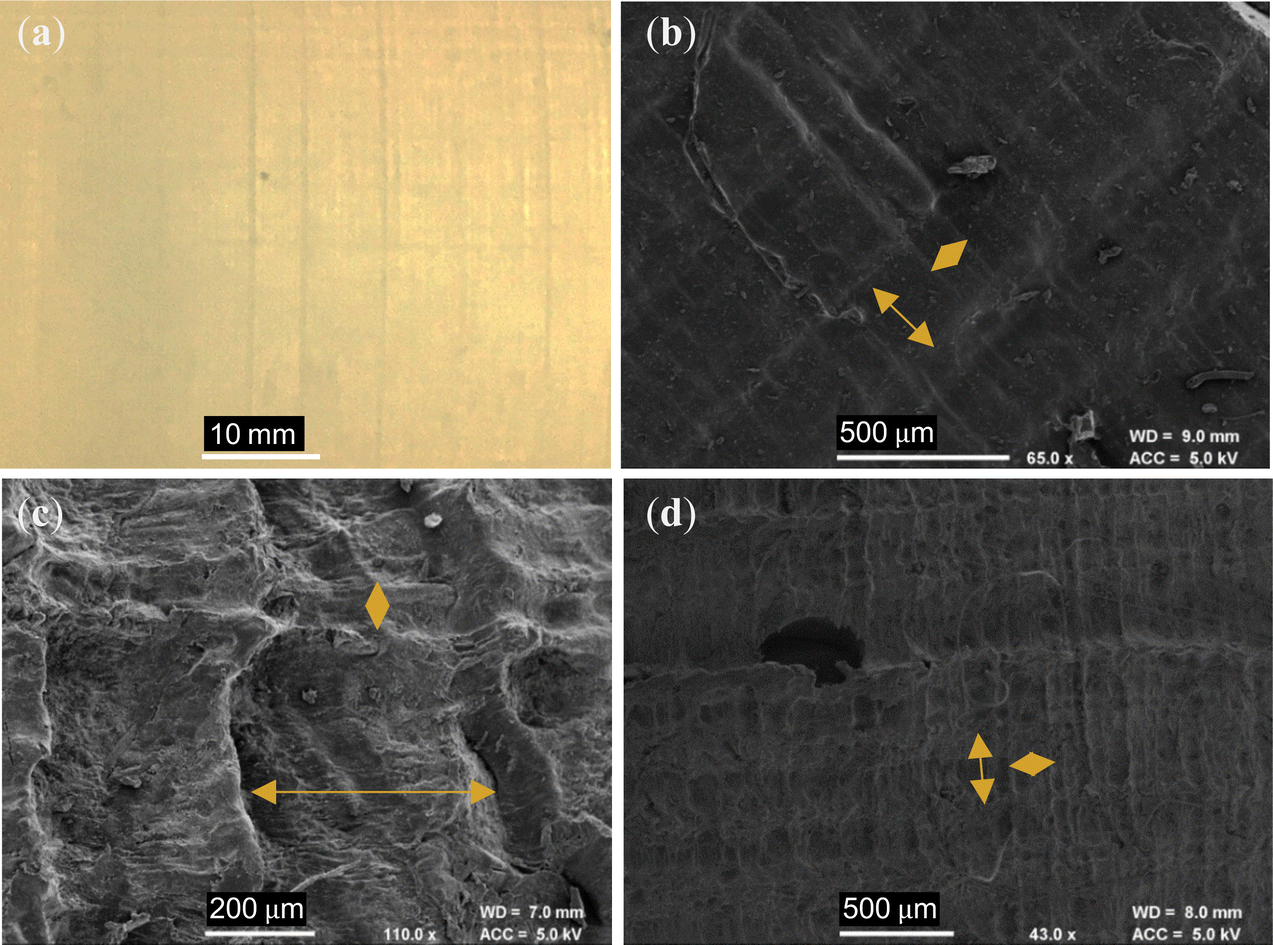 | ||
| Fig. 6 (a) Layers of cured resin on the mould exterior arise from the resolution of the SLA printer laser and are (b) visible under SEM. Orange arrows indicate repeating 0.3 by 0.1 mm checker patterns. This has then been transferred to the exterior of (c) composite and (d) PIM-1 monoliths during casting. | ||
3.2. Mechanical characteristics of PIM-1 and PIM-1:AX21 composite monoliths
To examine mechanical properties and evaluate if monoliths are of sufficient strength for handling and insertion into a pressure vessel, both PIM-1 and PIM-1:AX21 composite monoliths were subjected to static uniaxial compression testing. As can be seen from Fig. 7a and b, both monoliths were of sufficient integrity for machining prior to testing, where similarities between internal structures can again be identified. Both monoliths were positioned with the thicker-walled end on the lower platen to offset instability, ensuring that the end with the highest void fraction would fail first. | ||
| Fig. 7 Processed pieces for compression testing from (a) PIM-1 and (b) PIM-1:AX21 monoliths. (c) Progression of compression test of PIM-1 monolith, highlighting graceful failure by parts. (d) Composite monolith pieces after compression testing, highlighting integrity. Compressive stress–strain curves for (e) PIM-1 and (f) PIM-1:AX21 monoliths. | ||
Stress–strain curves are presented in Fig. 7e and f, where it can be seen that the PIM-1 monolith and composite monolith expressed a progressive, or graceful, failure, whereby failure occurred stepwise. This is beneficial, as it means some damage can occur to the material without complete failure of the entire part, an ability likely arising from the internal structure of the monoliths. This is in contrast to previously tested monoliths21 which became progressively denser, behaving similar to a compressed powder, further evidencing a material change induced by the novel forming process.
Whereas the PIM-1 monolith expressed multiple failures, corresponding to the different regions of porosity along the monolith length, each successively less voided and therefore stronger, the composite monolith failed in a single event. Post compression, the PIM-1 monolith had fractured to a rough powder, whereas the composite monolith was ejected from the Instron at first failure with roughly half its length intact; see Fig. 7d. Hence, the composite monolith expressed a stiffer response, where the highest possible compressive load was not necessarily achieved before test termination.
Both monoliths achieved a considerable compressive strength (5.47 and 6.69 MPa, respectively) approximately 1000 times greater than previously reported.21 The inclusion of AX21 increased the Young's modulus of the monoliths from 0.18 to 0.26 GPa (Table 2), in agreement with AX21 being a much stiffer material than PIM-1, although the internal structure of the monolith may also have an impact on the properties. It was seen previously that the inclusion of AX21 reduced the tensile strength of PIM-1 films, however here, AX21 has improved the compressive strength of monoliths. This may be due to the strength being dominated by the macro-porous architecture, which exhibits some differences between the two systems, see Fig. 5. Experiments may wish to assess how composite loading ratios affect compressive characteristics so that this may be optimised in the future. Importantly, in contrast to foams, both monoliths achieved much higher uniaxial compressive strength (∼6 MPa) than has been previously reported.21 This represents an important first step to developing these materials for use inside compression vessels.
| Composition | Compressive strength (MPa) | Yield strength (MPa) | Young's modulus (GPa) | Strain to first failure |
|---|---|---|---|---|
| PIM-1 | 5.47 | 1.21 | 0.180 | 0.027 |
| PIM-1:AX21 | 6.69 | 4.57 | 0.256 | 0.044 |
3.3. Porosity
It is appreciated that BET surface areas between batches of PIM-1 can vary, largely dependent upon the distribution of polymer chain lengths. In addition, there have been difficulties standardising how this value is derived, and some have pointed to reproducibility issues within the field.28 Hence, it is important to both characterise the surface area of the starting materials and then how this has been conveyed into resultant forms.Fig. 8 presents the N2 adsorption isotherms (77 K) of the starting materials PIM-1 and AX21. AX21 illustrates a Type I isotherm, indicative of extensive microporosity, with desorption following the adsorption trace almost identically. Interestingly, desorption isotherms could not be taken for the PIM-1 powder within the same timeframe (∼45–55 h). Likewise, it was only practicable to collect a five-point isotherm for the PIM-1 film, and both the PIM-1 and composite monoliths (∼80–86 h). Although these are sufficient for estimation of BET surface areas and constants, see Table 3, neither could the isotherm type nor pore size distribution be established from this data. Whilst still being within the range of surface area expected for PIM-1 (600–800 m2 g−1), when cast into films the polymer showed a reduced surface area (674 m2 g−1) in comparison to the pristine powder (762 m2 g−1). Although BET surface areas are theoretically unaffected by forming, simply the increased material mass may have led to a disparity between mass transport rates and the timeframe of pressure equilibration during isotherm collection. Therefore, although the BET surface areas here may not represent absolute values, they may be better understood as a comparison of the adsorption performance across various forms.
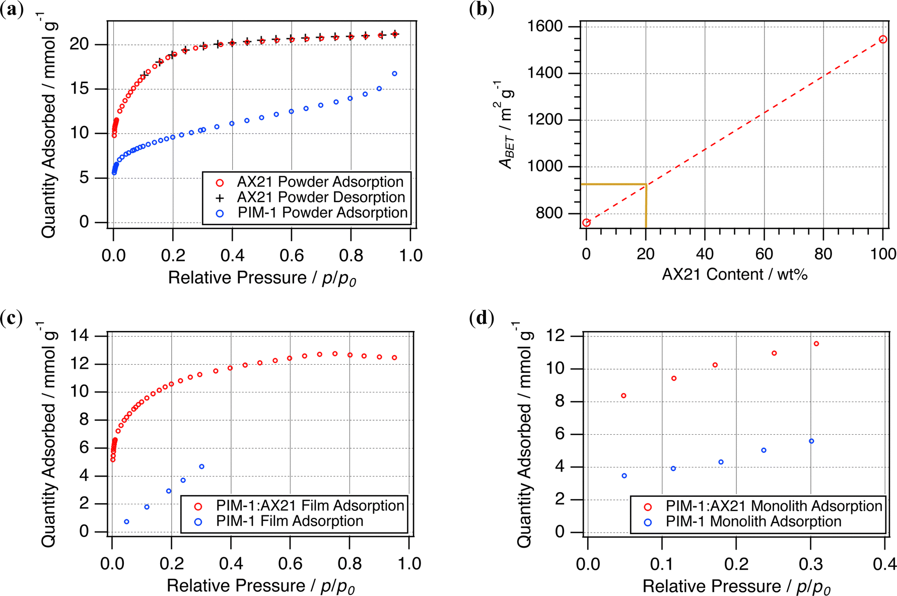 | ||
| Fig. 8 (a) N2 (77 K) adsorption isotherms for starting powders and (b) rule of mixtures for these materials. N2 (77 K) adsorption isotherms attained for resulting (c) films and (d) monoliths. | ||
| Sample | A BET (m2 g−1) | C |
|---|---|---|
| PIM-1 powder | 762 ± 4 | 232 |
| AX21 powder | 1547 ± 9 | 117 |
| PIM-1 film | 674 ± 18 | 224 |
| PIM-1:AX21 film | 850 ± 6 | 211 |
| PIM-1 monolith | 354 ± 2 | 197 |
| PIM-1:AX21 monolith | 847 ± 8 | 213 |
As anticipated, the AX21 powder had a much higher BET surface area than that of PIM-1, and hence was expected to increase surface areas when incorporated as a filler. Previously, this has been found to generally follow the rule of mixtures17 yielding 1.4% wt hydrogen adsorption in films at 20% wt loading. Therefore 20% wt loading with AX21 was expected to yield a BET surface area of approximately 925 m2 g−1; see Fig. 8b. The value determined for composite films (850 m2 g−1) was 8.4% lower than this prediction, but is similar to that achieved by the composite monolith (847 m2 g−1). This is unlike the PIM-1 monolith, which showed a marked reduction in BET surface area, only 354 m2 g−1, compared to the corresponding film or powder, again likely due to extended mass transport issues in the larger structure. Although this may be investigated further using gravimetric physisorption analysis to determine adsorption rates, SEM micrographs (Fig. 9) have been used here to examine the composite interface to infer the effects of forming upon porosity.
 | ||
| Fig. 9 SEM micrographs of (a and b) PIM-1 film cross section and (c) surface. (d and e) Composite film cross section and (f) primarily AX21 surface. (g and h) Internal surfaces of PIM-1 foams, highlighting evidence of solvent templating. (i–l) Internal surfaces of composite and (m–o) PIM-1 monoliths. Labelled orange boxes indicate zoom locations for subsequent micrographs. | ||
Fig. 9a and b show a PIM-1 film cross section, displaying the protrusions typically apparent in the appearance of PIM-1, similar to that seen in powders (Fig. S3a–c, ESI†). This film also seems to have formed an outer layer of denser material (highlighted by orange box), not present in the composite film; see Fig. 9d and e. When a composite film is cast, the components separate and AX21 sinks, causing it to bend on drying.29 The primarily polymeric face of this film, see Fig. 9c, was relatively smooth and featureless in comparison to that composed mostly of AX21, see Fig. 9f. It may be that AX21 disrupts the PIM-1 layer, providing origin for the improved mass transport.
In the case of anisotropic freeze casting of foams, PIM-1 foams present some evidence of solvent templating, where the solute has been rejected by the directional freeze front of the solvent, inducing microstructures aligned to this axis, see Fig. 9g and h. This may be beneficial for low pressure drop applications. This was not seen in the composite foam, where again the filler appeared to have separated, suggesting that solutions did not remain frozen.
For the monoliths, whilst it was seen in earlier micrographs that external surfaces of both monoliths were almost identical, internal surfaces revealed differing morphologies between species. The composite monolith in Fig. 9i–l expressed a broad range of surface types, where pores around 2 μm across (Fig. 9j) have been opened across an otherwise featureless surface, and tears reveal the characteristic PIM-1 structure inside (Fig. 9k). In contrast, internal surfaces of pristine PIM-1 monoliths (Fig. 9m–o) had a highly smooth and glassy texture, where thin layers appear to have fractured (Fig. 9n) and tears revealed no porous PIM-1 structure (Fig. 9o). The hierarchal porosity seen only in the composite monolith, from macropores (Fig. 9j), to mesopores (Fig. 9k) down to the intrinsic microporosity, may provide the basis for the improved mass transport and BET surface areas observed. Moreover, whole particles of AX21 could not be identified across several micrographs, further indicating the success of the process in retaining frozen chloroform and homogenous mixing of components given that they could not separate whilst frozen. Here, AX21 possibly disrupts the formation of the PIM-1 interface, facilitating gas penetration into the material.
4. Conclusions and future work
The novel forming process was successful in that PIM-1 matrixes could be freeze cast into controlled and repeatable three-dimensional geometries or monoliths, as well as include high surface area particulate fillers, such as AX21. The design of the additional thermal mass in the mould was significant, as this acted as a heat sink when cooled, allowing freeze casting even from volatile organics such as chloroform. Specifically, 3D SLA printing of the mould allowed it to withstand cyclic cooling cycles in liquid nitrogen and will facilitate more complex designs in the future. Although compression of the mould occurred at low temperatures, this was found to imprint designs onto monoliths to a sub-mm scale, and may be optimised in future as a forming parameter.By forming PIM-1 and PIM-1 based composites in this way, resultant adsorbent monoliths achieved a greater thickness and density than those previously reported for thin films. Moreover, monoliths appeared to contain controlled internal macrostructures, believed to relate to the relationship between convection and the mould geometry. This allowed monoliths to fail in compression by graceful failure as well as to achieve a strain-to-failure reasonably compatible with state-of-the-art hydrogen compression vessels. Inclusion of 20% wt. AX21 yielded stiffer and compressively stronger monoliths, and improved BET surface areas approximately in agreement with the rule of mixtures. Future experiments will aim to determine the extent of filler loading possible in order to maximise these benefits without loss of integrity. Although forming adsorbents into thicker monoliths did somewhat appear to impede mass transport, inclusion of AX21 alleviated these issues, possibly by disrupting the PIM-1 interface and instead facilitating transport through hierarchal porosity.
More systematic studies are now underway to further develop this approach. The aptness for the method to be scaled will be addressed, attempting various geometries to assess flexibility. High pressure hydrogen isotherms will also allow examination of monolith performance under more realistic conditions as well as determination of their potential effectiveness as a hydrogen store. The process was designed to be amenable to uptake as well as to be generically applied across a range of materials. Hence it is postulated that, just as has been seen with films, a series of monoliths can now be explored, taking advantage of the many powerful adsorbent classes already developed, bringing physisorbents closer to real world application.
Author contributions
Conceptualisation, A. D. B., C. R. B. and T. J. M.; methodology, G. M. N. and R. J.; formal analysis, G. M. N.; investigation, G. M. N., R. J., J. P. and M. T.; writing – original draft preparation, G. M. N.; writing – review and editing, G. M. N., R. J., J. P, M. T., A. D. B, C. R. B. and T. J. M.; visualisation, G. M. N. and R. J.; supervision, A. D. B., C. R. B. and T. J. M.; project administration, A. D. B., C. R. B. and T. J. M.; funding acquisition, T. J. M.Conflicts of interest
There are no conflicts to declare.Acknowledgements
This work was supported by the Engineering and Physical Sciences Research Council EP/L016354/1. Gratitude is extended to Dr Philip J. Fletcher for training in SEM (MC2, University of Bath). Also to Dr John Lowe, Dr Rémi Castaing and Dr Martin Levere as NMR, BET and GPC instrument specialists at the materials and chemical characterisation facility, respectively. Special thanks to Clare Ball (Senior Technician in structures and materials testing at the University of Bath) for preparation and training in compression testing as well as collection of XRCT data. Also to Dr James Roscow (Department of Mechanical Engineering, University of Bath) for providing equipment and advice on freeze casting.References
- L. Schlapbach and A. Züttel, Hydrogen-storage materials for mobile applications, Nature, 2001, 414(6861), 353–358, DOI:10.1038/35104634.
- A. M. Abdalla, S. Hossain, O. B. Nisfindy, A. T. Azad, M. Dawood and A. K. Azad, Hydrogen production, storage, transportation and key challenges with applications: A review, Energy Convers. Manage., 2018, 165, 602–627, DOI:10.1016/j.enconman.2018.03.088.
- UK Government, Department for Business, Energy & Industrial Stratergy.
- C. Ward, K. Hazra and K. Potter, Development of the manufacture of complex composite panels, Int. J. Mater. Prod. Technol., 2011, 42(3–4), 131–155 CrossRef CAS.
- P. F. Liu, J. K. Chu, S. J. Hou, P. Xu and J. Y. Zheng, Numerical simulation and optimal design for composite high-pressure hydrogen storage vessel: A review, Renewable Sustainable Energy Rev., 2012, 16(4), 1817–1827, DOI:10.1016/j.rser.2012.01.006.
- A. Ahmed, S. Seth, J. Purewal, A. G. Wong-Foy, M. Veenstra and A. J. Matzger, et al., Exceptional hydrogen storage achieved by screening nearly half a million metal-organic frameworks, Nat. Commun., 2019, 10(1), 1568, DOI:10.1038/s41467-019-09365-w.
- V. Garg, S. S. Mallick, P. Garcia-Trinanes and R. J. Berry, An investigation into the flowability of fine powders used in pharmaceutical industries, Powder Technol., 2018, 336, 375–382, DOI:10.1016/j.powtec.2018.06.014.
- Q. Fu, L. Wen, L. Zhang, X. Chen, D. Pun and A. Ahmed, et al., Preparation of Ice-Templated MOF–Polymer Composite Monoliths and Their Application for Wastewater Treatment with High Capacity and Easy Recycling, ACS Appl. Mater. Interfaces, 2017, 9(39), 33979–33988, DOI:10.1021/acsami.7b10872.
- S. H. Pang, M. L. Jue, J. Leisen, C. W. Jones and R. P. Lively, PIM-1 as a Solution-Processable “Molecular Basket” for CO2 Capture from Dilute Sources, ACS Macro Lett., 2015, 4(12), 1415–1419, DOI:10.1021/acsmacrolett.5b00775.
- C. A. Jeffs, M. W. Smith, C. A. Stone, C. G. Bezzu, K. J. Msayib and N. B. McKeown, et al., A polymer of intrinsic microporosity as the active binder to enhance adsorption/separation properties of composite hollow fibres, Microporous Mesoporous Mater., 2013, 170, 105–112, DOI:10.1016/j.micromeso.2012.11.039.
- F. Zhang, Y. Ma, J. Liao, V. Breedveld and R. P. Lively, Solution-Based 3D Printing of Polymers of Intrinsic Microporosity, Macromol. Rapid Commun., 2018, 39(13), 1800274, DOI:10.1002/marc.201800274.
- T. Mitra, R. S. Bhavsar, D. J. Adams, P. M. Budd and A. I. Cooper, PIM-1 mixed matrix membranes for gas separations using cost-effective hypercrosslinked nanoparticle fillers, Chem. Commun., 2016, 52(32), 5581–5584, 10.1039/C6CC00261G.
- S. Rochat, K. Polak-Kraśna, M. Tian, T. J. Mays, C. R. Bowen and A. D. Burrows, Assessment of the long-term stability of the polymer of intrinsic microporosity PIM-1 for hydrogen storage applications, Int. J. Hydrogen Energy, 2019, 44(1), 332–337, DOI:10.1016/j.ijhydene.2018.02.175.
- K. Polak-Kraśna, R. Dawson, L. T. Holyfield, C. R. Bowen, A. D. Burrows and T. J. Mays, Mechanical characterisation of polymer of intrinsic microporosity PIM-1 for hydrogen storage applications, J. Mater. Sci., 2017, 52(7), 3862–3875, DOI:10.1007/s10853-016-0647-4.
- D. Ramimoghadam, S. E. Boyd, C. L. Brown, A. G. E. Mac and C. J. Webb, The Effect of Thermal Treatment on the Hydrogen-Storage Properties of PIM-1, Chem. Phys. Chem., 2019, 20(12), 1613–1623, DOI:10.1002/cphc.201900222.
- S. Rochat, K. Polak-Kraśna, M. Tian, L. T. Holyfield, T. J. Mays and C. R. Bowen, et al., Hydrogen storage in polymer-based processable microporous composites, J. Mater. Chem. A, 2017, 5(35), 18752–18761, 10.1039/C7TA05232D.
- M. Tian, S. Rochat, K. Polak-Kraśna, L. T. Holyfield, A. D. Burrows and C. R. Bowen, et al., Nanoporous polymer-based composites for enhanced hydrogen storage, Adsorption, 2019, 25(4), 889–901, DOI:10.1007/s10450-019-00065-x.
- H. Frentrup, K. E. Hart, C. M. Colina and E. A. Müller, In Silico Determination of Gas Permeabilities by Non-Equilibrium Molecular Dynamics: CO2 and He through PIM-1, Membranes, 2015, 5(1), 99–119, DOI:10.3390/membranes5010099.
- F. Y. Li, Y. Xiao, T.-S. Chung and S. Kawi, High-Performance Thermally Self-Cross-Linked Polymer of Intrinsic Microporosity (PIM-1) Membranes for Energy Development, Macromolecules, 2012, 45(3), 1427–1437, DOI:10.1021/ma202667y.
- K. L. Scotti and D. C. Dunand, Freeze casting – A review of processing, microstructure and properties via the open data repository, FreezeCasting.net, Prog. Mater. Sci., 2018, 94, 243–305, DOI:10.1016/j.pmatsci.2018.01.001.
- A. Ahmed, T. Hasell, R. Clowes, P. Myers, A. I. Cooper and H. Zhang, Aligned macroporous monoliths with intrinsic microporosity via a frozen-solvent-templating approach, Chem. Commun., 2015, 51(9), 1717–1720, 10.1039/C4CC08919G.
- T. Otowa, R. Tanibata and M. Itoh, Production and adsorption characteristics of MAXSORB: High-surface-area active carbon, Gas Sep. Purif., 1993, 7(4), 241–245, DOI:10.1016/0950-4214(93)80024-Q.
- P. M. Budd, E. S. Elabas, B. S. Ghanem, S. Makhseed, N. B. McKeown and K. J. Msayib, et al., Solution-Processed, Organophilic Membrane Derived from a Polymer of Intrinsic Microporosity, Adv. Mater., 2004, 16(5), 456–459, DOI:10.1002/adma.200306053.
- ASTM D695-10, Standard Test Method for Compressive Properties of Rigid Plastics, West Conshohocken, ASTM International, 2010.
- C. A. Schneider, W. S. Rasband and K. W. Eliceiri, NIH Image to ImageJ: 25 years of image analysis, Nat. Methods, 2012, 9(7), 671–675, DOI:10.1038/nmeth.2089.
- J. Rouquerol, P. Llewellyn and F. Rouquerol, Is the bet equation applicable to microporous adsorbents? In: P. L. Llewellyn, F. Rodriquez-Reinoso, J. Rouqerol and N. Seaton, ed. Studies in Surface Science and Catalysis: Elsevier; 2007. p. 49–56 Search PubMed.
- Y. Shiina, K. Fujimura, T. Kunugi and N. Akino, Natural convection in a hemispherical enclosure heated from below, Int. J. Heat Mass Transfer, 1994, 37(11), 1605–1617, DOI:10.1016/0017-9310(94)90176-7.
- D. P. Broom and M. Hirscher, Irreproducibility in hydrogen storage material research, Energy Environ. Sci., 2016, 9(11), 3368–3380, 10.1039/C6EE01435F.
- K. Polak-Kraśna, M. Tian, S. Rochat, N. Gathercole, C. Yuan and Z. Hao, et al., Solvent Sorption-Induced Actuation of Composites Based on a Polymer of Intrinsic Microporosity, ACS Appl. Polym. Mater., 2021, 3(2), 920–928, DOI:10.1021/acsapm.0c01215.
Footnotes |
| † Electronic supplementary information (ESI) available: Fig. S1: 1H NMR spectrum PIM-1 [CDCl3], Fig. S2: GPC chromatogram for PIM-1 powder, Table S1: physical properties extracted from chromatogram for PIM-1, Fig. S3: SEM micrographs of PIM-1 and AX21 powder, Fig. S4: DMTA results for PIM-1 film, Fig. S5: SEM micrographs of PIM-1 film cross sections before and after self-crosslinking, Fig. S6: boiling of frozen precursor chloroform solutions resulting in PIM-1 foams, Fig. S7: schematic summary of the anisotropic freeze casting method used to produce foams, Fig. S8: equipment used to SLA print the elastomer mould, Fig. S9: SLA-printed mould, Fig. S10: schematic of convection inside mould cavity during freezing, Video S1: video method for the monolith freeze casting process. See DOI: https://doi.org/10.1039/d2ma00710j |
| ‡ University of Exeter, Exeter, EX4 4QF, UK. E-mail: M.Tian@exeter.ac.uk |
| This journal is © The Royal Society of Chemistry 2022 |