
 Open Access Article
 This Open Access Article is licensed under a Creative Commons Attribution-Non Commercial 3.0 Unported Licence
Template-free formation of oriented oxide nanowalls via topotactic-like pseudomorphic transformation: [110]-MgO(111) nanowall arrays†
Tsutomu
Shinagawa
 *ab and
Masanobu
Izaki
b
*ab and
Masanobu
Izaki
b
aElectronic Materials Research Division, Morinomiya centre, Osaka Research Institute of Industrial Science and Technology (ORIST), Osaka 536-8553, Japan. E-mail: tshina@orist.jp
bGraduate School of Engineering, Toyohashi University of Technology, Toyohashi, Aichi 441-8580, Japan
First published on 2nd August 2022
Abstract
Oxide nanowall arrays having aligned growth orientation and aligned wall crystal planes are a challenge to form on substrates without the use of templates. Here, oriented magnesium oxide (MgO) nanowall (NW) arrays with a [110] growth direction and (111) wall surfaces are prepared using a template-free spontaneous route: electrodeposition of magnesium hydroxide (Mg(OH)2) and its topotactic-like pseudomorphic transformation (TPT). Oriented Mg(OH)2 NWs were prepared on a conductive substrate using simple electrochemical deposition from a Mg(NO3)2 aqueous solution, and were characterized using scanning electron microscopy, X-ray diffraction, Fourier-transform infrared (FTIR) spectroscopy and Raman spectroscopy. The obtained Mg(OH)2 is a vertical nanowall array structure (∼660 nm height and 20–40 nm thickness) intersecting each other, with a [11![[2 with combining macron]](https://www.rsc.org/images/entities/char_0032_0304.gif) 0] growth orientation and a (0001) wall surface. The size of NWs can be controlled by electrodeposition time and deposition current density. Heat treatment of the [110]-Mg(OH)2(0001) NW arrays at 500 °C and 800 °C in air led to the formation of [110]-MgO(111) NW arrays via the TPT process. The chemical state analysis of NW surfaces using X-ray photoelectron microscopy and FTIR spectroscopy revealed that MgO NWs heated at 500 °C exhibit a superior CO2 adsorption property compared to the Mg(OH)2 NWs and MgO NWs heated at 800 °C.
0] growth orientation and a (0001) wall surface. The size of NWs can be controlled by electrodeposition time and deposition current density. Heat treatment of the [110]-Mg(OH)2(0001) NW arrays at 500 °C and 800 °C in air led to the formation of [110]-MgO(111) NW arrays via the TPT process. The chemical state analysis of NW surfaces using X-ray photoelectron microscopy and FTIR spectroscopy revealed that MgO NWs heated at 500 °C exhibit a superior CO2 adsorption property compared to the Mg(OH)2 NWs and MgO NWs heated at 800 °C.
Introduction
In general, the thermal decomposition of metal hydroxide results in the formation of the corresponding metal oxide (M(OH)2x → MOx + xH2O). Although this oxide conversion involves complex processes such as bond cleavage, bond formation and atomic rearrangement, certain layered metal hydroxides (LMHs) exhibit topotactic-like conversion (apparent preservation of the atomic framework).1–4 Furthermore, the conversion is pseudomorphic (retaining the original crystal shape) and results in a porous structure composed of numerous oxide nanograins and nanovoids because of volume shrinkage (typically ∼50%).2–4 This topotactic-like pseudomorphic transformation (TPT) allows the spontaneous formation of oxide consisting of aggregates of crystallographically oriented oxide particles, without the use of templates.The formation of LMHs with ordered crystal morphology and aligned orientation is therefore the key to utilizing this TPT feature to obtain crystallographically oriented oxide nanostructures on 2D or 3D supports such as flat substrates and metal foams.5–7 Well-faceted LMH particles with plate-like nano- and microstructures have been synthesized,8–10 but aligning them vertically with a preferred growth orientation is a challenge. If they can be aligned in a template-free manner, the oriented oxide nanostructures can be obtained on the 2D or 3D supports by a completely template-free route.
In this article, we demonstrate that the combination of (i) electrochemical deposition of plate-like LMHs on substrates and (ii) their TPT process allows for the template-free formation of oxide nanowall arrays having aligned growth direction and wall planes (Scheme 1). Vertically aligned nanowall structures are increasingly attracting attention as (photo)electrocatalysts, sensors, adsorbents and energy generation/storage materials due to their extremely large specific surface area that can be accessed from the outside.11,12
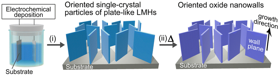 | ||
| Scheme 1 Schematic illustration of the template-free formation of oxide nanowalls oriented on substrates by (i) electrochemical deposition of oriented layered metal hydroxide (LMH) plate-like particles and (ii) their topotactic-like pseudomorphic transformation (TPT) to oxide. | ||
To demonstrate this synthetic strategy, we used magnesium hydroxide, Mg(OH)2 (hexagonal brucite type). Mg(OH)2 is a representative LMH and shows topotactic-like thermal decomposition above ∼300 °C to give magnesium oxide, MgO (cubic NaCl-type structure) with a crystallographic orientation relationship of Mg(OH)2(0001)[110]//MgO(111)[1![[1 with combining macron]](https://www.rsc.org/images/entities/char_0031_0304.gif) 0].1,13,14 Here, we performed a simple electrodeposition method to form Mg(OH)2 nanowalls (NWs) with a [110] growth orientation grown directly on substrates. By their TPT process, MgO NWs with a [110] growth orientation and (111) wall planes were successfully obtained for the first time to the best of our knowledge. In addition, the controllability of the size of the Mg(OH)2 NWs was investigated and the ambient CO2 adsorption state of these NWs was clarified.
0].1,13,14 Here, we performed a simple electrodeposition method to form Mg(OH)2 nanowalls (NWs) with a [110] growth orientation grown directly on substrates. By their TPT process, MgO NWs with a [110] growth orientation and (111) wall planes were successfully obtained for the first time to the best of our knowledge. In addition, the controllability of the size of the Mg(OH)2 NWs was investigated and the ambient CO2 adsorption state of these NWs was clarified.
Results and discussion
Electrodeposition and characterization of Mg(OH)2 NWs oriented on substrates
Mg(OH)2 NWs were electrochemically deposited using Sn:In2O3-coated glass (ITO) substrates as the cathode in an aqueous solution of 50 mM (M = mol L−1) Mg(NO3)2 at 85 °C. The plausible deposition reactions are described as follows:15,16| NO3− + H2O + 2e− → NO2− + 2OH− | (1) |
| H2O + e− → 1/2H2 + OH− | (2) |
| Mg2+ + 2OH− → Mg(OH)2 | (3) |
Field-emission scanning electron microscopy (FESEM) images of deposits obtained by applying a constant cathodic current (−2.0 mA cm−2) for 4.2 min (0.5 C cm−2) are shown in Fig. 1a. Vertically aligned hexagonal nanowall arrays (height = ∼660 nm and thickness = ∼20–40 nm) were homogeneously observed across the substrate. The nanowalls crossed at random, thus forming a number of submicron vertical channels that reached from the top of the wall to the substrate.
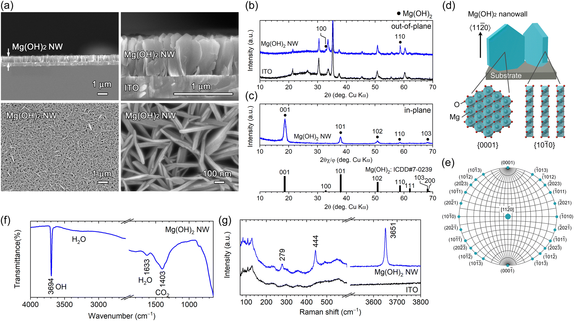 | ||
| Fig. 1 (a) Cross-sectional (top) and surface (bottom) FESEM images at different magnifications, (b) out-of-plane and (c) in-plane XRD patterns, (d) structural schematic, (f) FTIR spectrum and (g) Raman spectrum of as-deposited Mg(OH)2 NW arrays electrodeposited on an ITO substrate. (e) Wulff net with the [110] zone axis, representing crystal planes parallel to the Mg(OH)2[110] direction. ICDD data (no. 007-0239) for β-Mg(OH)2 (brucite) is presented in (c). | ||
The θ–2θ (out-of-plane) X-ray diffraction (XRD) pattern of the as-deposited nanowall is shown in Fig. 1b. All diffraction peaks were attributed to Mg(OH)2 (ICDD no. 007-0239) or the ITO substrate; no other phases were detected. A peak attributed to Mg(OH)2 110 was observed at 2θ = 58.68° (2θ = 58.64°; ICDD no. 007-0239) along with a slight Mg(OH)2 100 peak at 32.82° (2θ = 32.84°; ICDD no. 007-0239), indicating that the obtained nanowall array is composed of plate-like Mg(OH)2 crystal grains with a 〈110〉 preferred growth orientation and certain nanowalls having a 〈100〉 orientation. In-plane XRD was used to examine the crystal plane perpendicular to the substrate. Intense Mg(OH)2 001 diffraction appeared at 2θ = 18.64° and relatively weak 101, 102, 110 and 103 diffractions were detected (Fig. 1c). The intense 001 peak shows the wall surface corresponds to the {0001} plane, which is parallel to the 〈110〉 growth direction in the hexagonal system as shown in Fig. 1d. In addition, the other observed planes, {101}, {102} and {103}, are parallel to the 〈110〉 direction (the corresponding Wulff net is displayed in Fig. 1e). The slight 110 diffraction observed is attributed to the minor Mg(OH)2 nanowalls with a 〈100〉 growth orientation.
So far, well-faceted hexagonal plate-like Mg(OH)2 particles have been synthesized using a hydrothermal method.17,18 The crystal shape and growth direction for the [110]-Mg(OH)2(0001) NWs obtained in this study can be explained in terms of surface energy. In equilibrium, crystal growth is faster in the direction perpendicular to the plane with high surface energy and the planes with lower surface energy are exposed to minimise the total surface energy. Therefore, when depositing crystal grains on a substrate, there is a tendency for the growth orientation to be perpendicular to the plane with high surface energy and to expose the planes with lower surface energy. The surface energy of Mg(OH)2 {0001}, {100} and {110} planes was reported to be 3.3, 14.0, and 28.5 meV Å−2 by calculation,19 respectively, predicting that hexagonal plate-like Mg(OH)2 grows in the preferred orientation of 〈110〉 with {0001} plane largely exposed. The agreement with the thermodynamic predictions suggests that the electrodeposition condition used in this study is possibly close to the equilibrium state. Furthermore, Mg(OH)2 NWs with a 〈100〉 growth orientation may have been formed as a minor component because the energy difference between {100} and {110} planes is relatively small.
The [110]-Mg(OH)2(0001) NWs obtained were characterized using attenuated total reflection Fourier-transform infrared (ATR-FTIR) spectroscopy and Raman spectroscopy. In the ATR-FTIR spectra (Fig. 1f), a strong and sharp peak attributed to the lattice OH group was observed at 3694 cm−1, which was a typical characteristic of Mg(OH)2,20 and the broad bands at ∼1633 and ∼1403 cm−1 were assigned to adsorbed H2O and CO2, respectively.21 A Raman peak typical to Mg(OH)2 was detected at 279, 444 and 3651 cm−1 (Fig. 1g), which were attributed to the lattice vibration mode (Eg and A1g) and internal O–H stretching vibration mode (A1g), respectively.22
Size control of Mg(OH)2 NWs
Controllability of the wall size (height, length and thickness) of the Mg(OH)2 NWs was explored by changing the deposition time from 4.2 min. Fig. 2 shows XRD patterns of Mg(OH)2 NWs electrodeposited at different deposition times of 0.42–12.5 min (corresponding to 0.05–1.5 C cm−2) with other deposition conditions unchanged. Intense 110 diffraction was observed with increasing deposition time, confirming the formation of Mg(OH)2 with a 〈110〉 preferred growth orientation. Cross-sectional and top-view FESEM images of the Mg(OH)2 NWs obtained are shown in Fig. 3a, revealing vertically aligned nanowall structures regardless of the deposition time. Their height and thickness estimated from FESEM images ranged from 0.2 to 1.5 μm and from 19 to 110 nm, respectively, and both increased linearly with increasing deposition time (Fig. 3b). This indicates that the Faraday current efficiency, i.e., deposition rate, is nearly constant during the electrodeposition. The aspect ratio (height/thickness) of the nanowall was calculated to be approximately 15 (Fig. 3c). This value is three times greater than that of the equilibrium shape reported in the literature, where Wulff's construction is calculated based on the surface energy of Mg(OH)2.19
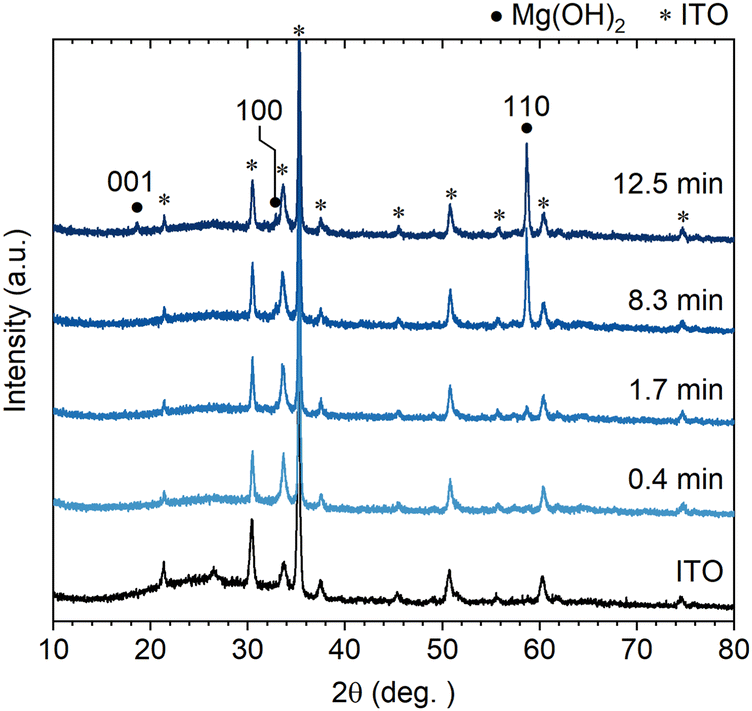 | ||
| Fig. 2 Out-of-plane XRD patterns of Mg(OH)2 NWs electrodeposited on an ITO substrate at different deposition times (0.4–12.5 min). | ||
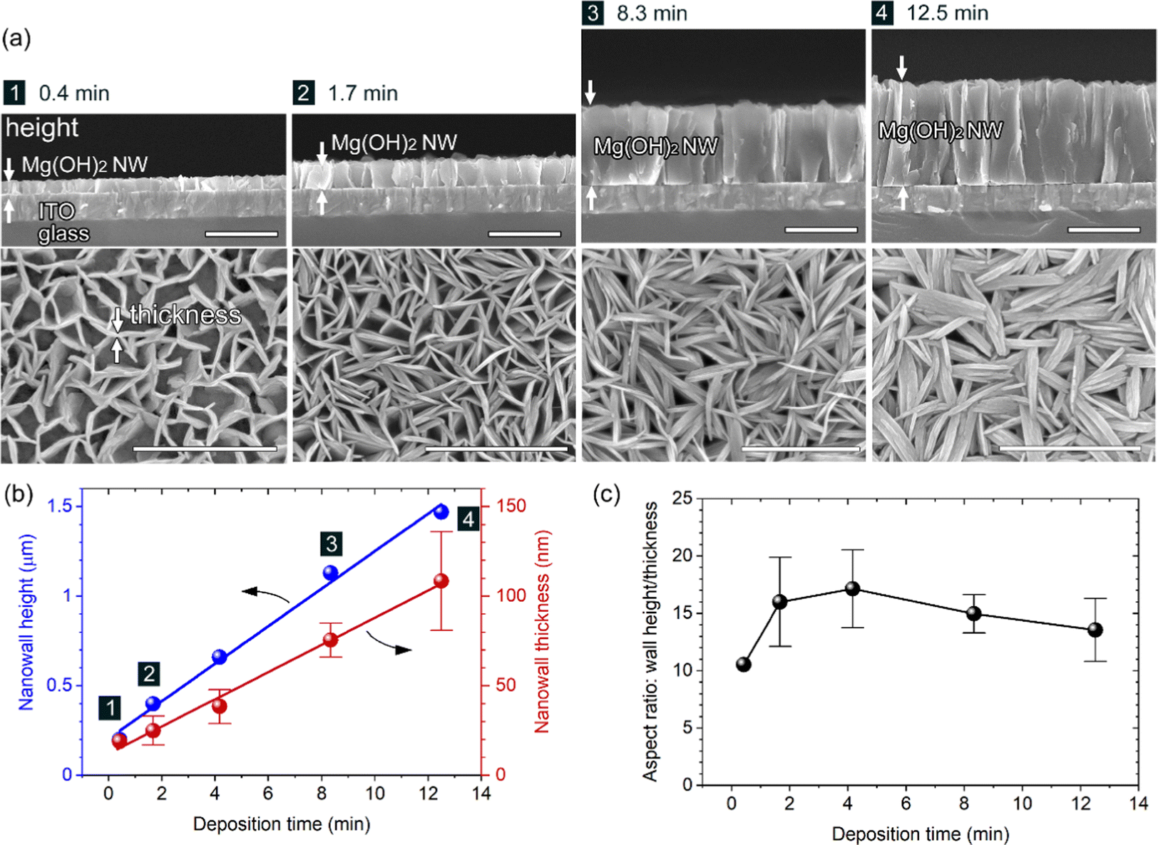 | ||
| Fig. 3 (a) Cross-sectional (top) and surface (bottom) FESEM images of Mg(OH)2 NWs electrodeposited on an ITO substrate at different deposition times (0.4–12.5 min). All scale bars represent 1 μm. Variation of the (b) NW height and thickness and (c) the aspect ratio as a function of the deposition time: no. 1–4 correspond to those in (a). | ||
The uniformity of nanowall height, as shown in Fig. 1a and 3a, is notable and can be attributed to the self-regulation mechanism of electrodeposition. Because Mg(OH)2 is electrically insulating, the cathodic reaction of Eq. (1) and (2) yielding OH− occurs primarily at the ITO/solution interface even after the growth of Mg(OH)2 NWs. The generated OH− can diffuse via the nanowall space to foam a diffuse layer with a higher pH and can react with Mg2+ to form Mg(OH)2 within the area. Therefore, the OH− diffusion layer defines the Mg(OH)2 growth region, resulting in a uniform wall height. Growth of ZnO nanorods with a similar electrodeposition mechanism yields uniform nanorod arrays with lengths of >3 μm.23
On the other hand, it was found that the length of the NWs could be controlled by adjusting the initial applied current. When the Initial current densities of −0.5 and −4.0 mA cm−2 were applied for 40 and 5 s, followed by a constant current of −2.0 mA cm−2 for ∼4.2 min, larger (400–500 nm length, ∼50 nm thickness) and smaller (280–400 nm length, ∼20 nm thickness) Mg(OH)2 grains were deposited at the same wall height (∼660 nm) respectively (FESEM images and XRD patterns are shown in Fig. S1 and S2 in the ESI,† respectively). This is because the initial current value determines the number of crystal nucleus per unit ITO surface area, which eventually determines the lateral length until it causes the steric interference between walls.
Thermal conversion to MgO NWs oriented on substrates
The Mg(OH)2 NW arrays corresponding to Fig. 1 were converted to MgO by heating at 500 °C and 800 °C for 2 h in air. Based on the TPT process, [10]-MgO(111) NWs are expected to be formed from [110]-Mg(OH)2(0001) NWs. FESEM observation of the resultant samples demonstrated that the vertically aligned nanowall structure was retained, and the wall height (∼660 nm) was almost unchanged at either temperature (Fig. 4a and b). Although no significant changes were observed on the wall surface at 500 °C, a porous structure in which ∼30 nm-diameter particles connected in 2D was observed at 800 °C (see also Fig. S3, ESI†). Moreover, larger particles and pores with a diameter of ∼100 nm were formed close to the substrate at 800 °C, probably due to structural disturbances caused by the [100]-Mg(OH)2 minor components.
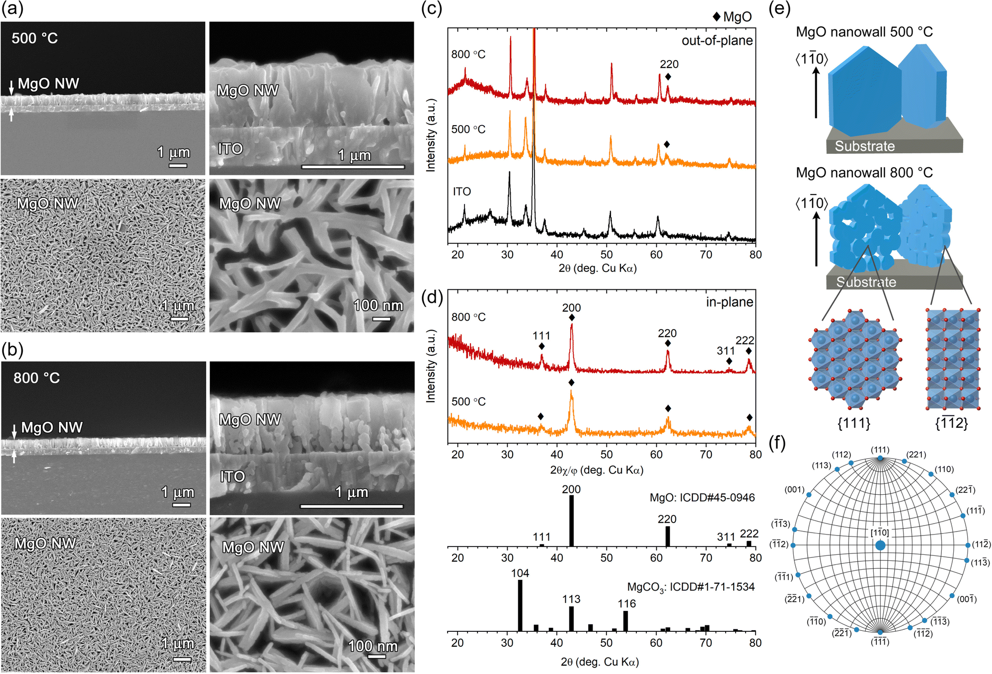 | ||
| Fig. 4 (a and b) Cross-sectional (top) and surface (bottom) FESEM images at different magnifications, (c) out-of-plane and (d) in-plane XRD patterns and (e) structural schematic of MgO NW arrays on an ITO substrate, obtained by heating Mg(OH)2 NWs at (a) 500 and (b) 800 °C. (f) Wulff net with the [10] zone axis, representing crystal planes parallel to the MgO[10] direction. ICDD data (no. 45-0946 and no. 1-71-1534) for MgO and MgCO3 are presented in (d). | ||
Fig. 4c and d show out-of-plane and in-plane XRD patterns of calcined samples. In the out-of-plane XRD, only a peak attributed to MgO 220 diffraction was detected at 2θ = 62.01° and 62.24° (2θ = 62.31°, ICDD no. 45-0946) for samples heated at 500 °C and 800 °C, respectively, except for those from the ITO substrate (Fig. 4c). The crystallite size estimated from the full width at half maximum (FWHM) of the 220 diffraction using the Scherrer equation was calculated to be 14.6 nm at 500 °C and 21.1 nm at 800 °C, indicating that single-crystal [110]-Mg(OH)2 nanowall was converted to nanocrystalline-assembled [10]-MgO nanowall (Fig. 4e), which is consistent with the topotactic-like transformation manner, Mg(OH)2(0001)[110]//MgO(111)[10].13 In the in-plane XRD, diffraction peaks attributed to MgO 111, 200, 220, 311 and 222 were detected (Fig. 4d), and all these planes are parallel to the [10] direction as indicated by the Wulff net of the MgO[10] zone axis (Fig. 4f). Regarding the relative intensity of the in-plane XRD peaks obtained, the overall pattern is similar to the ICDD powder pattern, while the 111 and 222 peaks are slightly stronger. This reflects the nanocrystalline nature of the generated MgO, the random in-plane orientation of the NWs and the wall surfaces corresponding to the (111) plane. Thus, oriented oxide nanowalls were obtained without the use of templates by combining the electrodeposition of oriented LMH and its TPT process.
Surface chemistry of Mg(OH)2 and MgO NWs
The chemical state of the three samples shown in Fig. 1 and 4, namely, as-deposited Mg(OH)2 NWs, and MgO NWs heated at 500 °C and 800 °C (all deposition times were 4.2 min), was examined using X-ray photoelectron spectroscopy (XPS). The XPS spectra of C 1s, O 1s, Mg 1s, and Mg KLL regions are shown in Fig. 5. Note that the XPS spectra primarily contained information about the top edge of the nanowall rather than the wall surfaces because of the high anisotropy of the sample shape and nano level detection depth of XPS measurements.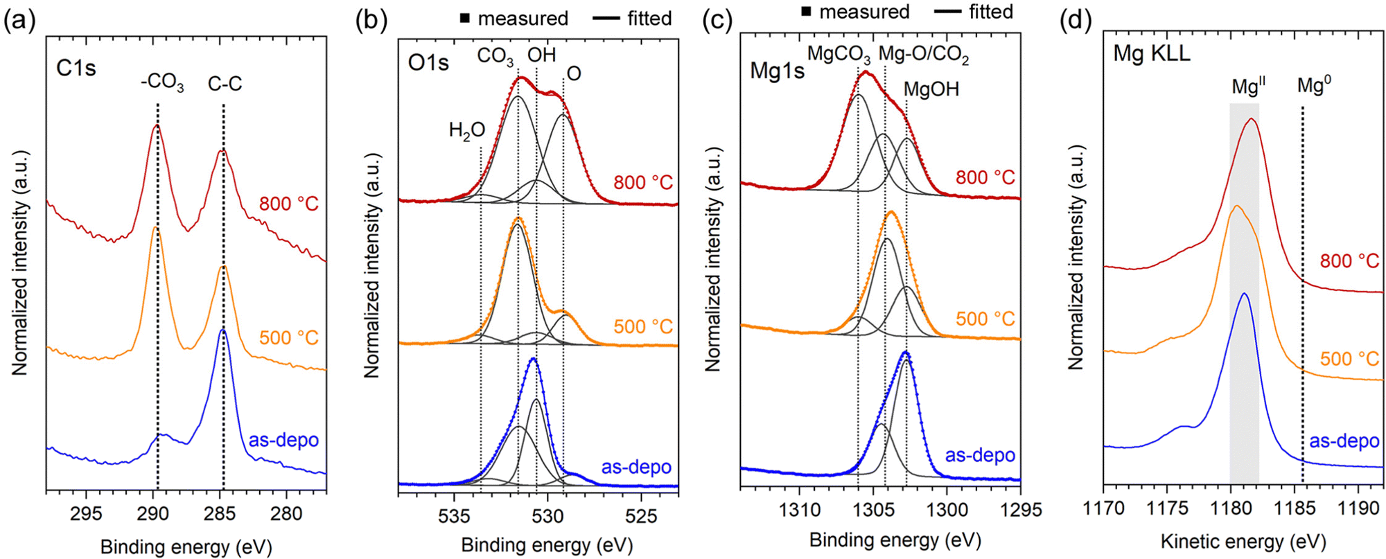 | ||
| Fig. 5 Normalized XPS spectra of as-deposited Mg(OH)2 and MgO NWs heated at 500 and 800 °C: (a) C 1s, (b) O 1s, (c) Mg 1s and (d) Mg KLL energy regions. | ||
The presence of -CO3 moiety was detected in the C 1s region for all samples (Fig. 5a); compared to the as-deposited Mg(OH)2, the heated MgO demonstrated a relatively strong -CO3 intensity. The -CO3 moiety also contributed to the O 1s XPS spectra (Fig. 5b). In addition to -OH and -O moieties at ∼530.6 and ∼529.1 eV respectively, -CO3 moiety was observed at ∼531.6 eV for all samples.24 In particular, MgO heated at 500 °C demonstrates a relatively intense -CO3 peak. In the Mg 1s spectra (Fig. 5c), the formation of magnesium carbonate (MgCO3, ∼1306.0 eV)25 was identified, in the MgO heated at 800 °C. In the XRD (Fig. 4c and d), no peaks corresponding to MgCO3 were detected, suggesting that the generated MgCO3 is a thin layer on the MgO surface. In contrast, MgCO3 was less present in MgO heated at 500 °C, instead a peak at ∼1304.2 eV due to lattice Mg-O and/or adsorbed CO2 was dominated.26,27 For the as-deposited Mg(OH)2, an intense hydroxide peak at ∼1302.7 eV was observed, and the presence of adsorbed CO2 and the absence of magnesium carbonate were confirmed.26,27 The Mg KLL spectra confirmed the presence of Mg in the divalent state in all samples, with no zerovalent state detected (Fig. 5d). These XPS results show that as-deposited Mg(OH)2 and heated MgO NWs can adsorb ambient CO2 at room temperature, and CO2 adsorbed on the Mg(OH)2 surface can be converted to MgCO3 heating up to 800 °C.
To compare the adsorption state of CO2 between the Mg(OH)2 and MgO NWs, ATR-FTIR measurements were performed. Because the detection depth of the ATR method using a diamond crystal is a few microns, the chemical state of the entire nanowall can be detected, unlike surface-sensitive XPS. ATR-FTIR spectra of Mg(OH)2 and MgO NWs corresponding to the samples shown in Fig. 1 and 4, are shown in Fig. 6a. With calcination, the O–H band at 3694 cm−1 characteristic of lattice OH disappeared and the peak intensity at ∼1408 cm−1 due to CO32− species21 increased significantly. Adsorption of CO2 on metal oxide surfaces yields mostly carbonates (CO32−) and bicarbonates (HCO3−).21 The IR peaks observed at ∼1408, 1087 and 855 cm−1 for MgO NWs heated at 500 °C correspond to monodentate carbonates on MgO (Mg–O–CO2).21 The inset of Fig. 6a compares the peak area at ∼1408 cm−1 (spectral range 1145–1605 cm−1), revealing that the MgO NWs heated at 500 °C had a prominent CO2 adsorption property. This is probably because the MgO obtained by heating at 500 °C has a larger surface area due to the formation of nanograins and increased reactivity due to lattice defects.28 In contrast, calcination at 800 °C will result in a decrease in both surface area and reactivity due to enhanced crystal growth.28 The peak width at ∼1408 cm−1 for MgO NWs heated at 800 °C is larger than that heated at 500 °C, indicating the presence of bulk thin-layer MgCO3 in addition to surface monodentate carbonates, as detected by the XPS measurements.
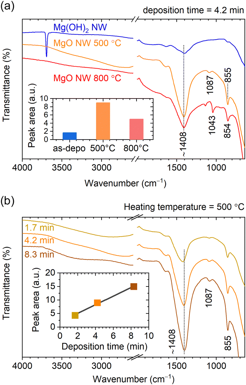 | ||
| Fig. 6 (a) ATR-FTIR spectra of as-deposited Mg(OH)2 and MgO NWs heated at 500 and 800 °C. (b) ATR-FTIR spectra of MgO NWs electrodeposited at different deposition times and heated at 500 °C. Both insets show the area of peaks at ∼1400 cm−1 because of adsorbed CO2. | ||
Fig. 6b shows ATR-FTIR spectra of MgO NWs with different wall heights of 0.40, 0.66 and 1.13 μm obtained from M(OH)2 NWs electrodeposited at different deposition times and heated at 500 °C (the XRD patterns of these MgO NWs are shown in Fig. S4, ESI†). Although the peak positions at ∼1408 cm−1 corresponding to monodentate carbonates remained constant,21 the peak intensity changed depending on the wall height. As shown in the inset, the peak area increases linearly with increasing wall height, indicating that the amount of CO2 adsorption is proportional to the wall area. In recent years, CO2 adsorption of MgO have attracted much attention,29–32 especially the high activity of the MgO(111) plane has been reported.33–37 Thus, the MgO(111) NWs obtained in this study are expected to have high CO2 adsorption potential.
Conclusions
We have demonstrated the template-free formation of crystallographically oriented MgO nanowall arrays using a combination of the hydroxide electrodeposition and the topotactic-like pseudomorphic transformation (TPT) process. Mg(OH)2 was electrochemically deposited on ITO substrates from an aqueous solution containing 50 mM Mg(NO3)2 at 85 °C by applying a constant cathodic current of −2.0 mA cm−2. The XRD and FESEM results confirmed uniform-height [110]-Mg(OH)2(0001) NWs vertically aligned on the ITO substrates. By adjusting deposition time and the initial deposition current density, the size of the NWs varied in the range of 0.2–1.5 μm in height, 0.28–0.4 μm in length and 19–110 nm in thickness.
Heat treatment of the oriented Mg(OH)2 NW arrays at 500 and 800 °C in air for 2 h resulted in the formation of [110]-MgO(111) NW arrays while retaining the original structural morphology via the TPT process. A distinct porous structure was observed on the walls of the MgO NW array heated at 800 °C. The XPS and ATR-FTIR results revealed that all samples adsorbed ambient CO2 to give monodentate carbonates and that their adsorption properties were significantly dependent on the heat treatment conditions. The MgO NWs heated at 500 °C showed a higher CO2 adsorption property among the samples and the amount of CO2 adsorption had a linear relationship to the wall area.
Experimental
Materials
Magnesium nitrate hexahydrate (Mg(NO3)2·6H2O, ≥99.0%) and Pt plate (99.95%) were purchased from FUJIFILM Wako Pure Chemical Co. and The Nilaco Co., and used as received. The aqueous solution was prepared using deionized water (>10 MΩ cm) purified using a Millipore Elix Advanced5 system. Sn-doped In2O3-coated glass/quartz (ITO, ∼5 Ω sq−1, GEOMATEC) was used as a substrate.Synthesis of Mg(OH)2 nanowalls
Before deposition, ITO substrates were treated with a UV-ozone cleaner and then rinsed with deionized water. Mg(OH)2 was electrochemically deposited using a potentiostat/galvanostat (Hokuto Denko HABF5001) and a conventional two-electrode glass vessel with the ITO substrate (working electrode) and the Pt plate (counter electrode). Electrodeposition was performed in an aqueous solution containing 50 mM Mg(NO3)2 using a cathodic constant current of −2.0 mA cm−2 at a total electrical charge of 0.05–1.5 C cm−2 at 85 °C. After deposition, the obtained deposits were rinsed with deionized water and dried in air.Synthesis of MgO nanowalls
MgO nanowalls were prepared by the calcination of electrodeposited Mg(OH)2 nanowalls in air at 500 °C or 800 °C for 2 h (heating rate = 10 °C min−1) using an electric muffle furnace. For samples heated at 800 °C, ITO-coated quartz was used.Characterization
Cross-sectional and surface FESEM images of deposits on the ITO substrate were obtained using a JEOL JSM-6700F operated at an acceleration voltage of 5.0 kV. θ–2θ and in-plane XRD patterns were obtained using a Rigaku SmartLab with Cu Kα radiation operated at 6 kW. ATR-FTIR spectra were recorded using a ThermoNicolet 4700 with a diamond reflection crystal unit (DuraSample IRII). Raman spectra were recorded on a microscopic laser Raman spectrometer (Horiba LabRAM HR Evolution) using laser light with a wavelength of 532 nm. XPS spectra were recorded with a Kratos AXIS-Ultra DLD using monochromated Al Kα radiation.Conflicts of interest
There are no conflicts to declare.Acknowledgements
This work was financially supported by a Grant-in-Aid for Scientific Research (C) (No. 18K05310) from JSPS.Notes and references
- R. R. Balmbra, J. S. Clunie and J. F. Goodman, Nature, 1966, 209, 1083–1084 CrossRef CAS
.
- M. Figlarz, B. Gérand, A. Delahaye-Vidal, B. Dumont, F. Harb, A. Coucou and F. Fievet, Solid State Ionics, 1990, 43, 143–170 CrossRef CAS
- R. Q. Song, A. W. Xu, B. Deng, Q. Li and G. Y. Chen, Adv. Funct. Mater., 2007, 17, 296–306 CrossRef CAS
- M. Hu, W. Yang, H. Tan, L. Jin, L. Zhang, P. Kerns, Y. Dang, S. Dissanayake, S. Schaefer, B. Liu, Y. Zhu, S. L. Suib and J. He, Matter, 2020, 2, 1244–1259 CrossRef
- T. Shinagawa, M. Watanabe, J.-I. Tani and M. Chigane, Cryst. Growth Des, 2017, 17, 3826–3833 CrossRef CAS
- T. Shinagawa, M. Chigane and M. Takahashi, Cryst. Growth Des., 2022, 22, 4122–4132 CrossRef CAS
- T. Shinagawa, M. Chigane and M. Izaki, ACS Omega, 2021, 6, 2312–2317 CrossRef CAS PubMed
- J. C. Yu, A. Xu, L. Zhang, R. Song and L. Wu, J. Phys. Chem. B, 2004, 108, 64–70 CrossRef CAS
- C. W. Kim, Y. S. Son, A. U. Pawar, M. J. Kang, J. Y. Zheng, V. Sharma, P. Mohanty and Y. S. Kang, J. Mater. Chem. A, 2014, 2, 19867–19872 RSC
- R. Ma, M. Osada, L. Hu and T. Sasaki, Chem. Mater., 2010, 22, 6341–6346 CrossRef CAS
- S. Xu, Y. Wen, Z. Chen, N. Ji, Z. Zou, M. Wu, L. Qu and J. Zhang, Angew. Chem., 2021, 133, 24710–24714 CrossRef
- Y. Wang, S. Chen, S. Zhao, Q. Chen and J. Zhang, J. Mater. Chem. A, 2020, 8, 15845–15852 RSC
- U. Dahmen, M. Kim and A. Searcy, Ultramicroscopy, 1987, 23, 365–370 CrossRef CAS
- J. Green, J. Mater. Sci., 1983, 18, 637–651 CrossRef CAS
- G. H. A. Therese and P. V. Kamath, Chem. Mater., 2000, 12, 1195–1204 CrossRef CAS
- G. H. A. Therese and P. V. Kamath, J. Appl. Electrochem., 1998, 28, 539–543 CrossRef CAS
- L. Kumari, W. Li, C. H. Vannoy, R. M. Leblanc and D. Wang, Ceram. Int., 2009, 35, 3355–3364 CrossRef CAS
- J. M. Hanlon, L. Bravo Diaz, G. Balducci, B. A. Stobbs, M. Bielewski, P. Chung, I. MacLaren and D. H. Gregory, CrystEngComm, 2015, 17, 5672–5679 RSC
- S. V. Churakov, M. Iannuzzi and M. Parrinello, J. Phys. Chem. B, 2004, 108, 11567–11574 CrossRef CAS
- B. Boev, G. Jovanovski and P. Makreski, Turkish J. Earth Sci., 2009, 18, 631–652 CAS
- W. Taifan, J.-F. Boily and J. Baltrusaitis, Surf. Sci. Rep., 2016, 71, 595–671 CrossRef CAS
- T. S. Duffy, C. Meade, Y. Fei, H.-K. Mao and R. J. Hemley, Am. Mineral., 1995, 80, 222–230 CAS
- T. Shinagawa and M. Izaki, RSC Adv., 2014, 4, 30999–31002 RSC
- Q. Cui, G. Jiao, J. Zheng, T. Wang, G. Wu and G. Li, RSC Adv., 2019, 9, 18641–18651 RSC
- E. R. L. Espiritu, G. R. da Silva, D. Azizi, F. Larachi and K. E. Waters, Colloids Surf., A, 2018, 539, 319–334 CrossRef CAS
- A. I. Ikeuba, B. Zhang, J. Wang, E.-H. Han, W. Ke and P. C. Okafor, J. Electrochem. Soc., 2018, 165, C180–C194 CrossRef CAS
- J. L. Chen and J. H. Zhu, Res. Chem. Intermed., 2019, 45, 947–950 CrossRef CAS
- R. Salomão and V. C. Pandolfelli, Ceram. Int., 2008, 34, 1829–1834 CrossRef
- N. McQueen, P. Kelemen, G. Dipple, P. Renforth and J. Wilcox, Nat. Commun., 2020, 11, 3299 CrossRef CAS PubMed
- M. T. Dunstan, F. Donat, A. H. Bork, C. P. Grey and C. R. Müller, Chem. Rev., 2021, 121, 12681–12745 CrossRef CAS PubMed
- Y. Hu, Y. Guo, J. Sun, H. Li and W. Liu, J. Mater. Chem. A, 2019, 7, 20103–20120 RSC
- S. Sun, H. Sun, P. T. Williams and C. Wu, Sustainable Energy Fuels, 2021, 5, 4546–4559 RSC
- G. A. Mutch, S. Shulda, A. J. McCue, M. J. Menart, C. V. Ciobanu, C. Ngo, J. A. Anderson, R. M. Richards and D. Vega-Maza, J. Am. Chem. Soc., 2018, 140, 4736–4742 CrossRef CAS PubMed
- J. Hu, K. Zhu, L. Chen, C. Kübel and R. Richards, J. Phys. Chem. C, 2007, 111, 12038–12044 CrossRef CAS
- K. Zhu, J. Hu, C. Kuebel and R. Richards, Angew. Chem., Int. Ed., 2006, 45, 7277–7281 CrossRef CAS PubMed
- C. A. Cadigan, A. R. Corpuz, F. Lin, C. M. Caskey, K. B. H. Finch, X. Wang and R. M. Richards, Catal. Sci. Technol., 2013, 3, 900–911 RSC
- M. D. Susman, H. N. Pham, A. K. Datye, S. Chinta and J. D. Rimer, Chem. Mater., 2018, 30, 2641–2650 CrossRef CAS
Footnote |
| † Electronic supplementary information (ESI) available: XRD patterns and FESEM images of Mg(OH)2 and MgO NWs. See DOI: https://doi.org/10.1039/d2ma00493c |
| This journal is © The Royal Society of Chemistry 2022 |