 Open Access Article
Designing a nickel(II) thiourea-formaldehyde polymer/nanocarbon bifunctional molecular catalyst with superior ORR, OER activities and its application to Zn–air battery†
Pandian
Ganesan‡
*a,
Aleksandar
Staykov
 a,
Albert
Mufundirwa
 b,
Takeharu
Sugiyama
b,
Hiroaki
Shu
c,
Mitsugu
Uejima
c and
Naotoshi
Nakashima
b,
Takeharu
Sugiyama
b,
Hiroaki
Shu
c,
Mitsugu
Uejima
c and
Naotoshi
Nakashima
 *a
*a
aInternational Institute for Carbon-Neutral Energy Research (I2CNER), Kyushu University, 744, Motooka, Nishi-ku, Fukuoka, 819-0395, Japan. E-mail: ganesan.sep86@gmail.com; nakashima.naotoshi.614@m.kyushu-u.ac.jp
bResearch Center for Synchrotron Light Applications, Kyushu University, 6-1 Kasuga-koen, Kasuga, Fukuoka 816-8580, Japan
cZeon Corporation, Chiyoda-ku, Tokyo 100-8246, Japan
First published on 2nd July 2022
Abstract
As efficient electrodes in energy conversion and storage devices, we focus on the development of a polymer-type non-precious metal-coordinated eco-friendly catalyst with high performance, which is of importance in flexible wearable energy storage electronic devices with adaptable shapes. In the present study, we describe the design and synthesis of a nickel (Ni)-coordinated poly(thiourea-formaldehyde) polymer, then a nanocarbon (Vulcan, porous nanocarbon CNovel™, 2-different multi-walled carbon nanotubes, or single-walled carbon nanotubes) as the conducting support was combined to prepare seven different molecular catalysts. The chemical structure of the Ni-coordinated polymer was characterized by elemental analysis, 13C NMR, FT-IR and XPS. Furthermore, EXAFS studies and theoretical calculations revealed that this polymer consists of two Ni–O (2.17 Å) and two Ni–S (2.17 Å) coordination bonds. This Ni-coordination polymer was stable in an oxidative and reductive environment in an alkaline medium over a long term due to its strong Ni-coordination. The catalysts were found to act as an efficient catalyst for an oxygen reduction reaction (ORR) and oxygen evolution reaction (OER). Especially, among the catalysts, the CNovel™-based catalyst showed the highest oxygen electrode performance for the ORR: E1/2: 0.81 V vs. RHE, and OER: 1.57 V vs. RHE at 10 mA cm−2. The catalyst acted as an efficient and durable cathode for a rechargeable Zn–air battery (charge–discharge overpotential gap of 0.45 V). Such outstanding air-cathode performance is explained by the cooperative mechanism between water on the axial site of the Ni in the polymer and superoxide ion on the porous carbon. The present study is of importance for the development of advanced energy materials in batteries and molecular catalysts.
1. Introduction
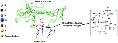
As fossil fuel energy is running out, the world is looking for alternative energy sources and devices. The metal–air battery and water electrolyzer are some successful candidates for future energy requirements.1–8 Recently, transition metal chalcogenides that exhibited a high electrocatalytic activity with low overpotentials have been reported as successful cost-effective cathode materials for metal–air batteries.9–17 Interestingly, the electrochemical transformation of transition metal chalcogenide cathodes showed high activity and durability compared to their pristine transition metal oxide analogs;9–12 namely, such modified metal chalcogenide performances have competed with those of state-of-the-art catalysts, such as Pt, IrO2, and RuO2.11–13 However, the performance and durability of such catalysts are still not appreciable compared to those of state-of-the-art catalysts.12–15 Recent reports showed that the surface oxidation of the transition metal sulfides is responsible for the lack of durability.13–25 In order to reduce the surface oxidation during long-term battery operations, several methods including the use of a stable spinel metal sulfide structure, incorporation of iron in the catalysts, etc., have been reported.26–28 It is difficult to design a catalyst that is highly structurally stable during charging and discharging; but the use of polymer-based catalysts in a fuel cell is one of the efforts to solve this issue.Recently, we reported that a iron–nickel–sulfide/carbon nanotube hybrid catalyst exhibited high oxidation reduction reaction (ORR) (E1/2 = 0.82 V), oxidation evolution reaction (OER) (potential@10 mA cm−2 = 1.55 V), and Zn–air battery and water electrolyzer performances.26 In this study, to further improve the stability of the metal sulfide active sites, we focused on a polymer-type catalyst, which is used for the development of a flexible eco-friendly catalyst. The presented catalyst is a Ni-coordinated flexible polymer-type molecular catalyst. The Ni is an earth-abundant inexpensive non-precious metal, and it is well-known that Ni provides efficient catalyst sites for both ORR and OER.26 Along this line, we designed and synthesized a new nickel-coordinated thiourea formaldehyde-based polymer, denoted (Ni-TUF)n, by a polycondensation reaction, then fabricated catalysts by combining it with a carbon support. As the carbon support, we selected carbon black (Vulkan), porous carbon (CNovel™, denoted as CN), single-walled carbon nanotubes (SWCNTs; ZEONNANO SG101) – the so-called super-growth SWCNTs, or multi-walled carbon nanotubes (Nikkiso-MWCNTs![[thin space (1/6-em)]](https://www.rsc.org/images/entities/char_2009.gif) 29–31 and Flotube-9000). CN is a carbon black having a high surface area (∼1800 m2 g−1), pore volume of ∼3 mL g−1 with a particle size of 3.5–150 nm and tap density of 0.02–0.2 g mL−1 in its inter-connected mesopores, with a 3-D structure. Notably, CN has a unique nanostructure; namely, it has a continuous porous structure (see SEM in the ESI,† Fig. S1). Fig. 1 shows a possible structure of a catalyst composed of the nickel coordinated thiourea polymer with a porous carbon (left) and a possible chemical structure of the Ni-coordinated polymer. Such a structure is demonstrated based on 13C NMR, FT-IR, XPS and extended X-ray absorption fine structure (EXAFS) studies. The synthesized (Ni-TUF)n polymer-based catalysts show superior ORR, and OER activity. In particular, catalysts composed of the polymer and CN exhibit better performance. Thus, it was used as the cathode of a Zn–air battery, and the fabricated battery showed superior performance. We discuss the cooperative mechanism of H2O on the nickel and superoxide ion on the carbon, that are responsible for the outstanding performance.
29–31 and Flotube-9000). CN is a carbon black having a high surface area (∼1800 m2 g−1), pore volume of ∼3 mL g−1 with a particle size of 3.5–150 nm and tap density of 0.02–0.2 g mL−1 in its inter-connected mesopores, with a 3-D structure. Notably, CN has a unique nanostructure; namely, it has a continuous porous structure (see SEM in the ESI,† Fig. S1). Fig. 1 shows a possible structure of a catalyst composed of the nickel coordinated thiourea polymer with a porous carbon (left) and a possible chemical structure of the Ni-coordinated polymer. Such a structure is demonstrated based on 13C NMR, FT-IR, XPS and extended X-ray absorption fine structure (EXAFS) studies. The synthesized (Ni-TUF)n polymer-based catalysts show superior ORR, and OER activity. In particular, catalysts composed of the polymer and CN exhibit better performance. Thus, it was used as the cathode of a Zn–air battery, and the fabricated battery showed superior performance. We discuss the cooperative mechanism of H2O on the nickel and superoxide ion on the carbon, that are responsible for the outstanding performance.
2. Experimental
2.1. Materials and method
Vulkan (XC-72R) and CNovel™ were obtained from the Cabot Chemical Co., Ltd, and Toyotanso Co., Ltd, respectively. Flotube 9000 (CNano) was purchased from the Hohsen Corp. The Nikkiso-MWCNTs and SWCNTs (ZEONNANO SG101) were provided from Nikkiso Co., Ltd, and Zeon Corp., respectively. Thiourea, nickel(II) nitrate hexahydrate and formaldehyde were purchased from the FUJIFILM Wako Pure Chemical Corporation. Potassium hydroxide, dimethyl acetamide and Nafion® were obtained from Sigma Aldrich. The PTFE membrane with a 3 μm pore diameter was purchased from Advantec Co., Ltd.The catalysts were characterized by elemental analysis, nuclear magnetic resonance (NMR), and X-ray diffraction (XRD, Rigaku Smartlab, 9kW AMK model). The structural morphologies of the catalysts were investigated by field-emission-scanning electron microscopy (FE-SEM, Joel, JSM-7900F, accelerating voltage = 5 kV). For the SEM characterization, the samples were coated with osmium by sputtering. Transmission electron microscopy (TEM) measurements were carried out using a JOEL (JEM-ARM200CF model) microscope (accelerating voltage: 80 kV for carbon samples and 200 kV for non-carbon samples). The catalysts were dispersed in isopropanol by sonication using a bath-type sonicator (Branson 5510). A few drops of the suspension were drop-cast onto a carbon-coated copper grid, and then dried for the TEM measurements. The X-ray photoelectron spectroscopy (XPS) of the catalysts was performed in a 10−9 mbar vacuum using an AXIS-ULTRA (Shimadzu, Co., Japan).
The XAFS (in fluorescence-detection mode) measurements were carried out using the Kyushu University beam line, BL 06, in the Saga Light Source (Tosu, Japan), in which a homemade in situ electrochemical XAFS cell was used. The EXAFS fitting was conducted using the equations described below,
 | (1) |
 | (2) |
| R(EXAFS) ≈ Rj + (Δu2)/2Rj | (3) |
2.2. Synthesis of nickel/thiourea formaldehyde polymer (Ni-TUF)n
0.2 mol of thiourea was mixed with 0.2 mol of formaldehyde (5 mL), and acetic acid was dropped in until the pH of the mixture reached pH 3. A 1 mol sample of Ni(NO3)2 was added to the mixture, stirred well, then refluxed for 6 h at 90 °C. The obtained viscous product was collected and washed well with 1 M NaOH, de-ionized water and methanol, then dried at room temperature for 1 day to obtain a light green compound, (Ni-TUF)n. Also, we synthesized (TUF)n without Ni.2.3. Synthesis of (Ni-TUF)n/carbon composites
A typical synthetic procedure is as follows: the prepared (Ni-TUF)n was sonicated in 40 mL of dimethyl acetamide (DMAc) for 2 h to which 50 mg of a carbon support material listed in Table 1 was added, then sonicated for 30 min. The obtained material was then filtered to remove the solvent, washed with methanol, followed by vacuum drying at room temperature overnight. Table 1 lists the obtained materials/catalysts, which were used for further structure characterization and electrochemical performance measurements including the ORR, OER and Zn–air battery performances in alkaline media.| Amount of (Ni-TUF)n | Carbon support (each 50 mg) | Abbreviation of catalyst |
|---|---|---|
| 10 mg | Carbon black (Vulcan XC72R) | (Ni-TUF)n/Vulkan-w/w:1/5 |
| 10 mg | MWCNTs (Flotube 9000) | (Ni-TUF)n/MWCNT(Flotube)-w/w:1/5 |
| 10 mg | MWCNTs (Nikkiso) | (Ni-TUF)n/MWCNT(Nikkiso)-w/w:1/5 |
| 10 mg | SWCNTs | (Ni-TUF)n/Zeon-CNT-w/w:110 |
| 5 mg | C-Novel™ (MH-00) | (Ni-TUF)n/CN-w/w:1/10 |
| 10 mg | C-Novel™ (MH-00) | (Ni-TUF)n/CN-w/w:1/5 |
| 30 mg | C-Novel™ (MH-00) | (Ni-TUF)n/CN-w/w:3/5 |
2.4. Electrochemical measurements
The ORR and OER were evaluated by linear sweep voltammetry (LSV) in an O2 saturated Ar atmosphere using an ALS CH instrument (model 704 EA). A typical three-electrode system with working, reference and counter electrodes were immersed in 0.1 and 1 M potassium hydroxide (KOH) aqueous electrolytes. Mercury/mercurous oxide (Hg/HgO) and a platinum coil purchased from BAS, Inc., were used as the reference electrode and the counter electrode, respectively. Both the OER and ORR measurements were carried out at a scan rate of 5 mV s−1. To compare the OER and ORR activities of the catalysts, commercial Pt/C (40%) and RuO2 catalysts were used. The catalyst ink was prepared using 5 mg of the catalyst dispersed in a 200 μL solution mixture consisting of isopropanol, DI water, and Nafion (5%) in the ratio 16![[thin space (1/6-em)]](https://www.rsc.org/images/entities/char_2009.gif) :
:![[thin space (1/6-em)]](https://www.rsc.org/images/entities/char_2009.gif) 3
3![[thin space (1/6-em)]](https://www.rsc.org/images/entities/char_2009.gif) :
:![[thin space (1/6-em)]](https://www.rsc.org/images/entities/char_2009.gif) 1, and dispersed using a bath-type sonicator (Branson 5540) for 30 min to obtain a homogeneous ink. A 1.5 μL aliquot was uniformly dispersed on a glassy carbon disk with an area of 0.07 cm2, then dried. The potentials were converted to the reversible hydrogen electrode (RHE) scale using the relationship RHE = E (Hg/HgO) + 0.91 V in 0.1 M KOH and RHE = E (Hg/HgO) + 0.98 V in the 1 M KOH electrolyte. The 0.91 and 0.98 V were obtained from the calibration of the Hg/HgO electrode under complete H2 saturation conditions in 0.1 and 1 M KOH, respectively.
1, and dispersed using a bath-type sonicator (Branson 5540) for 30 min to obtain a homogeneous ink. A 1.5 μL aliquot was uniformly dispersed on a glassy carbon disk with an area of 0.07 cm2, then dried. The potentials were converted to the reversible hydrogen electrode (RHE) scale using the relationship RHE = E (Hg/HgO) + 0.91 V in 0.1 M KOH and RHE = E (Hg/HgO) + 0.98 V in the 1 M KOH electrolyte. The 0.91 and 0.98 V were obtained from the calibration of the Hg/HgO electrode under complete H2 saturation conditions in 0.1 and 1 M KOH, respectively.
2.5. Zn–air battery assembly
The Zn–air battery was assembled using an air battery set-up (Rigaku Corporation). We used a gas diffusion layer (GDL) for the electrode preparation. A zinc sheet and Whatman filter paper (51–55 μm pore size) in 6 M KOH was used as the anode and separator. The other set of the catalyst dispersion was then poured into the same membrane filter to make another layer to obtain a two-sided catalyst-coated cathode electrode, which was used as the Zn–air battery assembly (working area = 28.27 cm2). The mass of the zinc metal was calculated by weighing the Zn metal before (for each battery assembly, we used 400 mg of Zn metal) and after the battery performance measurements. The specific capacity was calculated by the following e.g. specific capacity = current × hours of battery operation/mass of the used zinc.3. Results and discussion
3.1. Synthesis and structural characterization
The synthesis of a nickel coordinated thiourea-formaldehyde polymer (Ni-TUF)n was carried out using a method involving the synthesis of the thiourea-formaldehyde polymer (TUF)n without Ni.31–38 The functional group unit in our polymer synthesized in the presence of Ni ions is expected to be –CH2–NH–C(![[double bond, length as m-dash]](https://www.rsc.org/images/entities/char_e001.gif) S)–NH–CH2–, the same as the reported polymer synthesized in the absence of Ni. We carried out elemental analysis of (Ni-TUF)n, and the result was: C = 27.64%, H = 5.19%, N = 25.62%, S = 29.7%, which indicated the elemental composition of (Ni-TUF)n as C15H22N12S6NiO2 (molecular weights,1937.86) because the calculated composition percentage for C15H22N12S6NiO2 is: C = 27.56.3%, H = 3.40%, N = 25.72%, S = 29.44%. For (TUF)n without Ni: C = 25.18%, H = 5.07%, N = 29.15%, S = 33.7%. For calcd. of C2H5N2S1O0.5, C = 24.72%, H = 5.20%, N = 28.84%, S = 33.00%.
S)–NH–CH2–, the same as the reported polymer synthesized in the absence of Ni. We carried out elemental analysis of (Ni-TUF)n, and the result was: C = 27.64%, H = 5.19%, N = 25.62%, S = 29.7%, which indicated the elemental composition of (Ni-TUF)n as C15H22N12S6NiO2 (molecular weights,1937.86) because the calculated composition percentage for C15H22N12S6NiO2 is: C = 27.56.3%, H = 3.40%, N = 25.72%, S = 29.44%. For (TUF)n without Ni: C = 25.18%, H = 5.07%, N = 29.15%, S = 33.7%. For calcd. of C2H5N2S1O0.5, C = 24.72%, H = 5.20%, N = 28.84%, S = 33.00%.
We then measured the solid state C13 NMR spectra of (Ni-TUF)n and (TUF)n, and the result is shown in Fig. 2, in which we observed two kinds of carbons in the (TUF)n and three kinds of carbon in the (Ni-TUF)n. For the (TUF)n, the characterized peak ‘a’ in Fig. 2 is due to the C![[double bond, length as m-dash]](https://www.rsc.org/images/entities/char_e001.gif) S splitting (182.34 ppm) and ‘b’ is due to the CH2 splitting (53 ppm).33,34 For the (Ni-TUF)n with nickel coordination, the chemical shift value observed at 183.1 ppm (‘a’ carbon) is due the C
S splitting (182.34 ppm) and ‘b’ is due to the CH2 splitting (53 ppm).33,34 For the (Ni-TUF)n with nickel coordination, the chemical shift value observed at 183.1 ppm (‘a’ carbon) is due the C![[double bond, length as m-dash]](https://www.rsc.org/images/entities/char_e001.gif) S group, while the chemical shift at 52 ppm denotes type ‘b’ carbon of the methyl group.33 There are two bands in the ‘b’ carbon in the (Ni-TUF)n at 76 and 66 ppm which are broadened, while such bands are not evident in the (TUF)n. This would be due to the electronic environmental changes in the neighboring nitrogen atoms. The chemical shifts at 61 and 53 ppm of (Ni-TUF)n are due to the methyl groups with and without branching, respectively. The other chemical shifts at 129.6 and 236 ppm of (TUF)n are characterized as the spinning sidebands of the C
S group, while the chemical shift at 52 ppm denotes type ‘b’ carbon of the methyl group.33 There are two bands in the ‘b’ carbon in the (Ni-TUF)n at 76 and 66 ppm which are broadened, while such bands are not evident in the (TUF)n. This would be due to the electronic environmental changes in the neighboring nitrogen atoms. The chemical shifts at 61 and 53 ppm of (Ni-TUF)n are due to the methyl groups with and without branching, respectively. The other chemical shifts at 129.6 and 236 ppm of (TUF)n are characterized as the spinning sidebands of the C![[double bond, length as m-dash]](https://www.rsc.org/images/entities/char_e001.gif) S carbon, and the chemical shifts at 76 and 69 ppm are the sidebands of the methyl group (CH2) carbon. Since the sidebands of the C
S carbon, and the chemical shifts at 76 and 69 ppm are the sidebands of the methyl group (CH2) carbon. Since the sidebands of the C![[double bond, length as m-dash]](https://www.rsc.org/images/entities/char_e001.gif) S carbon in the (Ni-TUF)n appeared at almost the same chemical shift as the (TUF)n, the coordination center of the polymer was not clearly based on the analysis of the solid state C13 NMR spectral data. The nature of the carbon in (Ni-TUF)n and (TUF)n was further investigated using FT-IR spectroscopy, and the results are shown in Fig. 3(a) and Table 2. The (Ni-TUF)n exhibits a strong band at 3318 cm−1, which is attributed to the stretching vibrations of the OH− as depicted in Fig. 3(b).30–33 The (TUF)n shows a broad band in the range 3270–2865 cm−1, which is due to the existence of adsorbed H2O molecules.
S carbon in the (Ni-TUF)n appeared at almost the same chemical shift as the (TUF)n, the coordination center of the polymer was not clearly based on the analysis of the solid state C13 NMR spectral data. The nature of the carbon in (Ni-TUF)n and (TUF)n was further investigated using FT-IR spectroscopy, and the results are shown in Fig. 3(a) and Table 2. The (Ni-TUF)n exhibits a strong band at 3318 cm−1, which is attributed to the stretching vibrations of the OH− as depicted in Fig. 3(b).30–33 The (TUF)n shows a broad band in the range 3270–2865 cm−1, which is due to the existence of adsorbed H2O molecules.
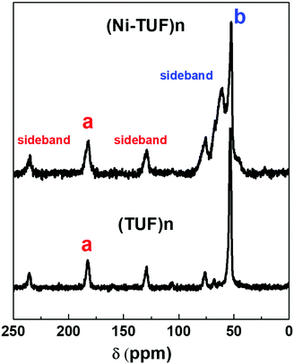 | ||
Fig. 2 Solid state NMR of the (Ni-TUF)n (top) and (TUF)n (bottom). ‘a’ and ‘b’ are characterized as C![[double bond, length as m-dash]](https://www.rsc.org/images/entities/char_e001.gif) S and CH2 splitting, respectively. S and CH2 splitting, respectively. | ||
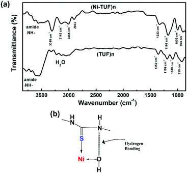 | ||
| Fig. 3 (a) FT-IR spectra of (Ni-TUF)n and (TUF)n and (b) suggested hydrogen bonding and Ni–S coordination. | ||
| Wavenumber/cm−1 for (Ni-TUF)n | Wavenumber/cm−1 for (TUF)n | Wavenumber/cm−1 for each attributed group taken from the literature24–27 | Attributed group |
|---|---|---|---|
| 3143 | Not found | ||
| 1333 | 1358 | 1340 | –NH– |
| 1171 | 1196 | 1140 | N–C(![[double bond, length as m-dash]](https://www.rsc.org/images/entities/char_e001.gif) S)–N S)–N |
| 1088 | 1002 | 1086 | –CH2– |
| 945 | 902 | 919 | –N–CH2–N– |
| 812 | 828 | Not found | |
| 710 | 717 | 709 | –N–C(![[double bond, length as m-dash]](https://www.rsc.org/images/entities/char_e001.gif) S)–N S)–N |
The (Ni-TUF)n exhibits absorption peaks in the range of 2903–3005 cm−1, which is attributed to the –CH– stretching vibrations.32,33 We observed a band at 3143 cm−1 for the (Ni-TUF)n, which is due to the hydrogen bonding of the –NH– group and the hydrogen of the hydroxyl group coordinated to the nickel atom, as presented in Fig. 3(b).33,34 This nitrogen in the –NH-group involved in the hydrogen bonding is responsible for the sideband broadening of the NMR spectrum of (Ni-TUF)n.34 In Table 2, we list the assignment of the FT-IR vibration peaks of –NH–, N–C(![[double bond, length as m-dash]](https://www.rsc.org/images/entities/char_e001.gif) S)–N, –CH2–, and –N–CH2–N– for (Ni-TUF)n and (TUF)n based on the reported data in the literature.32–36
S)–N, –CH2–, and –N–CH2–N– for (Ni-TUF)n and (TUF)n based on the reported data in the literature.32–36
X-ray photoelectron spectroscopy (XPS) studies were carried out for (Ni-TUF)n and (TUF)n to obtain the binding energies of the S 2p, N 1s and C 1s. As shown in Fig. 4(a), the S 2p binding energy bands of (Ni-TUF)n and (TUF)n appear at 161.0 and 160.0 eV, respectively, which correspond to the S2− band. We observed a 1.0 eV positive shift in the (Ni-TUF)n, which is derived from the complex formation between the sulfur and Ni.13,19
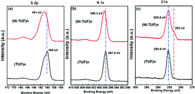 | ||
| Fig. 4 (a), (b) and (c) are, respectively, the S 2p, N 1s and C 1s XPS spectra of (Ni-TUF)n (red) and (TUF)n (black). | ||
In the N 1s region, the (Ni-TUF)n and (TUF)n exhibit binding energies at 398.3 and 397.8 eV, respectively (Fig. 4(b)).38 The 0.5 eV positive binding energy shifts in the (Ni-TUF)n compared to the (TUF)n could be explained by the coordination of the S and Ni through possible hydrogen bonding between the hydrogen of the hydroxyl group coordinated to the nickel and nitrogen in the polymer chain as depicted in Fig. 5.
The (Ni-TUF)n and (TUF)n show binding energies at 285.6 eV (Fig. 4(c)) in the C 1s region, which is due to the characteristics of the sp2 carbon bonded to nitrogen. Unlike (TUF)n, the (Ni-TUF)n shows a shoulder peak at ∼283 eV, which is due to the C–C bond, and confirms the presence of the branched methyl group in the polymer chain. The FT-IR peak that appeared at 3143 cm−2 supports this explanation.38,39 We observed binding energies at 530.61 and 530.53 eV for (Ni-TUF)n and (TUF)n, respectively, suggesting that both compounds contain the oxygen moiety as water or a hydroxyl group (see the ESI,† Fig. S2). The morphologies using SEM and TEM are shown in the ESI,† Fig. S3, in which the formation of agglomerated structures is obvious. In Fig. S3(c) (ESI†), the black-colored part shows the Ni-sites and the rest is CN.
3.2. Theoretical simulations
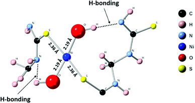
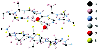
First principles simulations were performed using the periodic boundary condition, density functional theory with generalized gradient approximation, Perdew–Burke–Ernzerhof (PBE) functional and numerical atomic orbital wavefunction (NAO) as implemented in the QuantumATK simulation package.40 Geometry optimization was carried out until the forces were minimized below 0.05 eV Å−2. In our simulations, we performed optimization of the linear polymer unit cell with relaxation of the atom positions and unit cell parameters. This optimization was followed by optimization of the 2 × 2 × 4 super cell which includes four polymer chains with four unit cells each. This relaxation was performed to account for inter-chain interactions. Finally, Ni(OH)2 was placed in the center of the simulations model. The geometry optimization, as depicted in Fig. 6, resulted in a four-coordinated Ni center which leaves two free coordination sites in the six-coordinated Ni structure for the catalytically active sites. The four ligands are two hydroxyl groups and two sulfurs from the polymer chain. Strong hydrogen bonds were formed between the OH group and –NH– groups from the polymer chain.3.3. Extended X-ray absorption fine structure (EXAFS)
In order to reveal the bonding nature and geometry of (Ni-TUF)n, we carried out extended X-ray absorption fine structure (EXAFS) measurements, and the results were analyzed using the nickel as an observer atom, oxygen and sulfur as the scatter atoms (Fig. 6), and using Ni–O and Ni–S paths. The variables of E0, S02, Nj, Rj, and σj listed in Table S1 (ESI†) and the model equation described in the Experimental (Materials and methods) section. For all the EXAFS data, the interatomic distances were obtained from solving the multiple path functions (Ni–O and Ni–S) and fitted using the first shell model in the radial distribution function results. The EXAFS analysis of (Ni-TUF)n and (Ni-TUF)n/CN-w/w:1/5 suggested the 4 coordination number with the Ni–O and Ni–S of which 2 are from Ni–O and 2 are from Ni–S, for both catalysts. Hence, both (Ni-TUF)n and (Ni-TUF)n/CN:w/w-1/5 exhibited the +2 oxidation state of nickel and planar geometry using the John–Teller distortion. Therefore, the axial ligands remain uncoordinated due to the elongation of the higher energy dx2−y2 orbital in the Ni+2 (d8-coordination geometry). These results agree with the theoretical simulation described above.The EXAFS results of (Ni-TUF)n using the first shell fitting (Fig. 7) showed that the Ni–O and Ni–S of (Ni-TUF)n exhibited bond lengths of 2.18 and 2.35 Å, respectively, and those of (Ni-TUF)n/CN:w/w-1/5, the bond lengths were 2.17 and 2.38 Å, respectively. Previous reports41–43 have suggested that both the Ni–O and Ni–S bonds possess similar bonding nature, but the Ni–O has slightly higher polarity. For the (Ni-TUF)n and (Ni-TUF)n/CN-w/w:1/5 in the ex situ mode, we observed a significant difference in the bond lengths of the Ni–O (2.19 Å) and Ni–S (2.36 Å) of about ±0.17 Å (Table S2, ESI†). This is due to the hydrogen bonding of the hydrogen atom in the (Ni-TUF)n which is bonded to the highly electronegative oxygen with the nitrogen in the polymer chain (Fig. 3(b)), and this is further evidenced by the FT-IR vibrational frequency at 3143 cm−1 that corresponds to hydrogen bonding (Fig. 3(a)) as well as the theoretical studies described above. Hence, the geometry in (Ni-TUF)n and (Ni-TUF)n/CN-w/w:1/5 is not completely planar, instead, it is suggested to be slightly deviated from the planar structure. This was also suggested by the XRD of (Ni-TUF)n (see the ESI,† Fig. S4), in which no crystalline peak was evident (very weak).
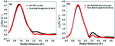 | ||
| Fig. 7 Ex situ EXAFS (black color) of (a) (Ni-TUF)n and (b) (Ni-TUF)n/CN:w/w:1/5, and their first shell fit model (red color). | ||
3.4. Electrochemical studies
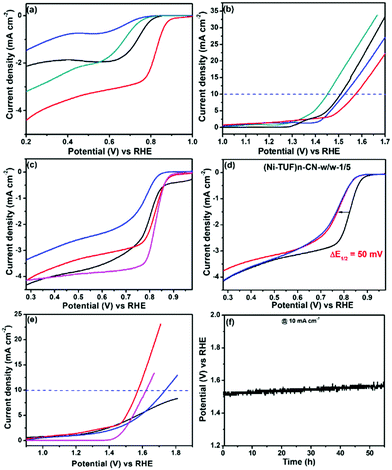
We measured the ORR and OER performance of the synthesized catalysts together with Pt/C and Ir/C for comparison in 0.1 M KOH aqueous solution using 1600 rpm rotating disk electrodes to obtain the electrocatalytic activity. As shown in Fig. 8(a), the ORR activity showed a strong dependence on the carbon supports used; namely, the half-wave potential (E1/2) of (Ni-TUF)n/CN-w/w:1/5 is 0.82 V vs. NHE, which is excellent performance among the state-of-the-art non-Pt catalysts,11,18 and superior compared to those of (Ni-TUF)n/MWCNT(Nikkiso)-w/w:1/5 (E1/2 = 0.65 V), and (Ni-TUF)n/Vulcan-w/w:1/5 (E1/2 = 0.73 V) as listed in Table 3. As shown in Fig. 8(b), the OER shows slightly different behavior; that is, when comparing the performance of the voltage at 10 mA cm−2, (Ni-TUF)n/CN-w/w:1/5 provided 1.57 V, which is comparable but slightly lower than that of (Ni-TUF)n/Vulkan-w/w:1/5 (1.51 V) and (Ni-TUF)n/MWCNT(Nikkiso)-w/w:1/5 (1.52 V) (Table 3).| Polymer catalysts | Oxygen reduction reaction (E1/2) (ORR) V vs. RHE | Oxygen evolution reaction (OER) at 10 mA cm−2 V vs. RHE | Oxygen electrode potential V vs. RHE |
|---|---|---|---|
| (Ni-TUF)n/CN-w/w:1/5 | 0.82 | 1.57 | 0.75 |
| (NiTUF)n/MWCNT(Nikkiso)-w/w:1/5 | 0.65 | 1.52 | 0.87 |
| (Ni-TUF)n/Vulcan-w/w:1/5 | 0.72 | 1.51 | 0.79 |
| (Ni-TUF)n/CN-w/w:1/10 | 0.79 | None | None |
| (Ni-TUF)n/CN-w/w:3/5 | 0.78 | 1.74 | 0.96 |
Based on the obtained ORR and OER values, the oxygen electrode potentials of (Ni-TUF)n/CN-w/w:1/5, (Ni-TUF)n/MWCNT(Nikkiso)-w/w:1/5, and (Ni-TUF)n/Vulkan-w/w:1/5 were calculated to be 0.75, 0.87 and 0.79 V, respectively. This result demonstrates that the performance of (Ni-TUF)n/CN-w/w:1/5 is better than that of the other two catalysts. The CN as the support provides the best performance among the three catalysts, which might be due to the highly mesoporous carbon structures that provide many efficient catalytic sites.
We then examined the impact of the weight ratios of (Ni-TUF)n and CN present – (Ni-TUF)n/CN-w/w:1/5, (Ni-TUF)n/CN-w/w:1/10 and (Ni-TUF)n/CN-w/w:3/5. As shown in Fig. 8(c), for the ORR, (Ni-TUF)n/CN-w/w:1/5 is better than (Ni-TUF)n/CN-w/w:1/10 and (Ni-TUF)n/CN-w/w:3/5, indicating the optimum ratio between the (Ni-TUF)n and the carbon support is 10 mg of Ni-(TUF)n and 50 mg of the CN carbon. Notably, the ORR performance of (Ni-TUF)n/CN-w/w:1/5 is very close to that of conventional Pt/C. One more issue we would like to consider is the high OER performance; namely, when comparing the performance of the voltage at 10 mA cm−2, (Ni-TUF)n/CN-w/w:1/5 showed better activity than those of (Ni-TUF)n/CN-w/w:1/10 and (Ni-TUF)n/CN-w/w:3/5. We emphasize that the OER activity of (Ni-TUF)n/CN-w/w:1/5 is superior compared to conventional IrO2 (Fig. 8(e)). Such obtained results are listed in Table 3. Such nanocarbon-species dependence and the molar-ratio effect on carbon supported-catalyst performance, has been observed in a previously published paper using FeIII-doped nickel sulfides/nanocarbon hybrid catalysts.23 In addition to the mesoporous carbon structures that have high porous area, the electronic interaction of the catalytic sites and the nanocarbon as a support are important for such high performance.
To further evaluate the ORR performances, accelerated durability tests were carried out by performing repeated potentio-dynamic cycling for 20![[thin space (1/6-em)]](https://www.rsc.org/images/entities/char_2009.gif) 000 cycles in the potential range of 0.2 to 1.0 vs. RHE at a scan rate of 50 mV s−1 in an O2-saturated atmosphere. The result is shown in Fig. 8(d), in which even after 10
000 cycles in the potential range of 0.2 to 1.0 vs. RHE at a scan rate of 50 mV s−1 in an O2-saturated atmosphere. The result is shown in Fig. 8(d), in which even after 10![[thin space (1/6-em)]](https://www.rsc.org/images/entities/char_2009.gif) 000, then 20
000, then 20![[thin space (1/6-em)]](https://www.rsc.org/images/entities/char_2009.gif) 000 cycles, the E1/2 of (Ni-TUF)n/CN-w/w:1/5 shifted by a negative potential of only ∼50 mV, and for 10
000 cycles, the E1/2 of (Ni-TUF)n/CN-w/w:1/5 shifted by a negative potential of only ∼50 mV, and for 10![[thin space (1/6-em)]](https://www.rsc.org/images/entities/char_2009.gif) 000–20
000–20![[thin space (1/6-em)]](https://www.rsc.org/images/entities/char_2009.gif) 000 cycles, while the ORR activity remained stable, indicating that the catalyst has robust durability. This durability is due to the presence of the S-atom in the thiourea formaldehyde polymer framework that forms dπ–dπ bonding, resulting in the transfer of the 3d-electrons from the Ni atom to the vacant 3d orbital of the S-atom.27 Such durability on (Ni-TUF)n/CN-w/w:1/5 is higher than that of (Ni-TUF/CN)n-w/w:1/10 and (Ni-TUF/CN)n-w/w:3/5 (see the ESI,† Fig. S5a and b), indicating that the complex nanostructures in the catalysts are important factors for their durability. We plotted the Tafel slops of the (Ni-TUF/CN)n-w/w:3/5, and IrO2 for both OER and ORR. For the ORR region, the (Ni-TUF/CN)n-w/w:3/5 and IrO2 exhibited Tafel slopes of 72 mV dec−1 and 98 mV dec−1, respectively (see the ESI,† Fig. S5c). For the OER region, the (Ni-TUF/CN)n-w/w:3/5 and IrO2 exhibited Tafel slopes of 78 mV dec−1 and 57 mV dec−1, respectively (see the ESI,† Fig. S5d). Such results indicated the superior bifunctional performance of the (Ni-TUF/CN)n-w/w:3/5.
000 cycles, while the ORR activity remained stable, indicating that the catalyst has robust durability. This durability is due to the presence of the S-atom in the thiourea formaldehyde polymer framework that forms dπ–dπ bonding, resulting in the transfer of the 3d-electrons from the Ni atom to the vacant 3d orbital of the S-atom.27 Such durability on (Ni-TUF)n/CN-w/w:1/5 is higher than that of (Ni-TUF/CN)n-w/w:1/10 and (Ni-TUF/CN)n-w/w:3/5 (see the ESI,† Fig. S5a and b), indicating that the complex nanostructures in the catalysts are important factors for their durability. We plotted the Tafel slops of the (Ni-TUF/CN)n-w/w:3/5, and IrO2 for both OER and ORR. For the ORR region, the (Ni-TUF/CN)n-w/w:3/5 and IrO2 exhibited Tafel slopes of 72 mV dec−1 and 98 mV dec−1, respectively (see the ESI,† Fig. S5c). For the OER region, the (Ni-TUF/CN)n-w/w:3/5 and IrO2 exhibited Tafel slopes of 78 mV dec−1 and 57 mV dec−1, respectively (see the ESI,† Fig. S5d). Such results indicated the superior bifunctional performance of the (Ni-TUF/CN)n-w/w:3/5.
3.5. In situ electrochemical EXAFS measurements during electrochemical reactions
The experimental in situ setup using Pt as a counter electrode, a Hg/HgO reference electrode, a working electrode and electrochemical cell specially constructed for the XAFS studies is displayed in Fig. 9. We analyzed the EXAFS data of (Ni-TUF)n and (Ni-TUF)n/CN-w/w:1/5 during the ORR region (0.81–0.91 V vs. RHE), non-faradaic region (0.1 V vs. RHE) and OER region (1.31–1.41 V vs. RHE). The first shell fitted the radial distribution functions of (Ni-TUF)n:w/w-1/5 at voltages 0.81, 0.91, 1.01, 1.31 and 1.41 V as shown in Fig. 10(a)–(e), respectively. The input parameters (E0, S02, Nj, Rj, and σj,) are listed in Table S1 in the ESI.† The bond lengths of the Ni–O and Ni–S for both (Ni-TUF)n and (Ni-TUF)n-w/w:1/5 are listed in Table 4. Compared to the ex situ bond lengths of (Ni-TUF)n/CN:w/w-1/5, the bond lengths of the Ni–O and Ni–S at 1.01 V vs. RHE are deformed by +0.08 and −0.02 Å, respectively, suggesting that the H2O molecules occupy the axial orbital of the nickel atom and there is a cooperative intermediate step between the adsorbed superoxide (OOH–) species on the porous carbon (CN) and H2O on the nickel atom (Fig. 11(a)). In the ORR region (0.71–0.91 V), compared to the Ni–O bond of (Ni-TUF)n/CN-w/w:1/5, the Ni–S bonds elongated to 2.41 Å, which demonstrated that the Ni center is slightly above the planar position and the H2O on the axial position of the Ni is close to the adsorbed superoxide species on the carbon, which favors easy desorption of OH− as shown in Fig. 11(b).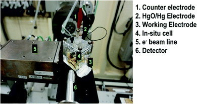 | ||
| Fig. 9 Electrochemical setup using a (Ni-TUF)n/CN:w/w-1/5 electrode at the Kyushu University beamline, BL06, in the Saga Light Source. | ||
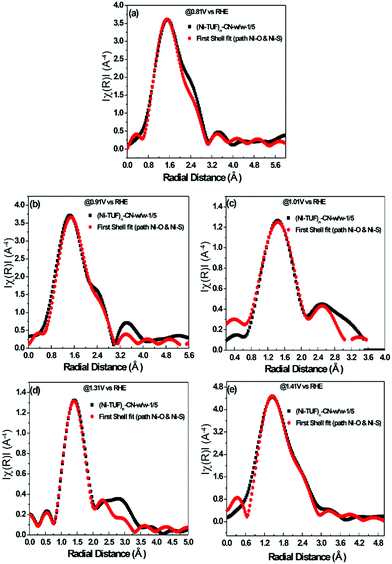 | ||
| Fig. 10 (a)–(e) In situ electrochemical EXAFS of (Ni-TUF)n/CN:w/w-1/5 electrode at voltages 0.81 V(a), 0.91 V(b), 1.01 V(c), 1.31 V (d) and 1.41 V (e) vs. RHE, based on the parameters described in the ESI,† Table S1. All the black colored curves show the raw XAFS data and all the red colored curves are the first shell fitting curves. | ||
| Applied voltages (V vs. RHE) | Interatomic distances of (Ni-TUF)n | Interatomic distances of (Ni-TUF)n/CN-w/w-1/5 | ||
|---|---|---|---|---|
| Ni–O (Å) | Ni–S (Å) | Ni–O (Å) | Ni–S (Å) | |
| 0.81 | 2.17 | 2.38 | 2.20 | 2.41 |
| 0.91 | 2.24 | 2.31 | 2.21 | 2.41 |
| 1.01 | 2.20 | 2.37 | 2.25 | 2.36 |
| Ex situ | 2.18 | 2.35 | 2.17 | 2.38 |
| 1.31 | 2.18 | 2.40 | 2.23 | 2.32 |
| 1.41 | 2.18 | 2.40 | 2.20 | 2.32 |
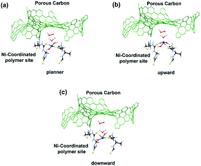
Meanwhile, in the OER region, the bond lengths of the Ni–S at the 1.31 and 1.41 V vs. RHE were 2.32 Å, which suggested that the nickel center shifted slightly downward from the planar position during the applied voltage, and the H2O on the axial position of the Ni center is not close as in the ORR voltage region, which favors the desorption of the H2O and O2 molecules (Fig. 11(c)). Furthermore, we analyzed the EXAFS results of the (Ni-TUF)n in the same voltage regions (see ESI,† Table S2 and Fig. S6). The bond lengths of (Ni-TUF)n are shown in Table 4. Unlike the carbon supported polymer, (Ni-TUF)n/CN-w/w:1/5, (Ni-TUF)n without the carbon support exhibited a similar bond length for both the ex situ and 1.01 V vs. RHE (non-faradaic voltage) (see Table 4). This showed the absence of a cooperative mechanism of the H2O and OOH− ions. Hence, although (Ni-TUF)n showed bond length changes at the OER and ORR voltages (Table 4), there is no catalytic performance which is different from the (Ni-TUF)n/CN-w/w.
3.6. Zn–air battery performance
We then evaluated the Zn–air battery performance using the catalyst, (Ni-TUF)n/CN-w/w:1/5, and the results are shown in Fig. 12. The cathode for the battery assembly was prepared by coating the (Ni-TUF)n/CN-w/w:1/5 on the GDL (Sigracet DGL2288). The primary testing of the battery in the initial cycle was carried out by discharging and charging separately as shown in Fig. 12(a). As the current density increases from 15 mA cm−2, the voltage for charge and discharge potentials are 1.80 and 1.35 V. Further increase in the current density resulted in an increase in the charge potentials by ∼2.4 V and decrease in discharge potentials by ∼1.2 V (Fig. 12(b)). The open circuit potential of (Ni-TUF)n/CN-w/w:1/5 exhibited 1.35 V before evaluation for the charge and discharge tests. Such high charge and discharge activities derive from the stable Ni–S active sites in the catalyst. However, as the current density increases over 30 mA cm−2, the Ni–S and Ni–O bonding increases drastically for (Ni-TUF)n, unlike the Ni–O and Ni–S bond length of (Ni-TUF)n/CN-w/w:1/5 as shown in Table 4. This is confirmed from the Ni–O and Ni–S bonding trends in the in situ EXAFS studies (Fig. 9 and Table 4), in which (Ni-TUF)n in Table 4 showed increased bond length compared to (Ni-TUF)n/CN-w/w:1/5 over the potential 1.01 V to 1.41 V. The rechargeable battery performance is shown in Fig. 12(b), which shows the current density versus voltage performance of (Ni-TUF)n/CN-w/w:1/5, and the battery shows the very low overpotential of 0.45 V, indicating an outstanding Zn–air battery performance when comparing the reported state-of-the-art Zn–air batteries,13,18 in which in many papers, the overpotentials were 0.62∼0.75 V. One of the important factors for the observed very high Zn–air battery using (Ni-TUF)n/CN-w/w:1/5 as the cathode material would be due to the cooperative H2O and superoxide ion mechanism of the electrochemical oxygen reduction and evolution reactions. Moreover, this polymer catalyst exhibited 0.45 V charge–discharge potential gap compared to the recently reported nickel iron sulfides (0.66 V)![[thin space (1/6-em)]](https://www.rsc.org/images/entities/char_2009.gif) 26 where the nickel sulfide is one of the active sites. This decrease in the charge–discharge potentials of (Ni-TUF)n/CN-w/w:1/5 due to the polymerized Ni-S sites in this catalyst compared to its crystalline Ni–S analogue site26 would be due to stabilization of the Ni–S and Ni–O sites in the (Ni-TUF)n polymer.
26 where the nickel sulfide is one of the active sites. This decrease in the charge–discharge potentials of (Ni-TUF)n/CN-w/w:1/5 due to the polymerized Ni-S sites in this catalyst compared to its crystalline Ni–S analogue site26 would be due to stabilization of the Ni–S and Ni–O sites in the (Ni-TUF)n polymer.
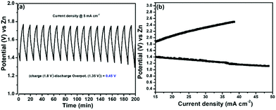 | ||
| Fig. 12 (a) Charge–discharge profile of (Ni-TUF)n/CN-w/w:1/5 and (b) current vs. voltage curve of (Ni-TUF)n/CN-w/w:1/5. | ||
4. Conclusions
A novel poly(nickel-thiourea-formaldehyde), (Ni-TUF)n, was designed and synthesized in one pot. For comparison, we also synthesized poly(thiourea-formaldehyde), (TUF)n. Their structures were characterized in detail using elemental analysis, solid state NMR, FT-IR and XPS, and we determined their chemical structures (see Fig. 1), in which the Ni forms a complex with the sulfur moieties in the polymer. Theoretical calculations and first shell fit of EXAFS showed that nickel is coordinated to four atoms: two Ni–S and two Ni–O. We revealed that there is hydrogen bonding between the coordinated oxygen and nitrogen in the polymer chain. We then prepared seven different catalysts by combining (Ni-TUF)n with carbon supports including conventional carbon black (Vulkan), unique porous carbon black (CN), and two different MWCNTs (Table 1). The (Ni-TUF)n supported on CN showed the highest ORR and OER bifunctional performances, which could be due to the formation of suitable nano-complex structures for the electrochemical reactions. In addition, the weight ratios of (Ni-TUF)n and CN in the catalysts were important for the higher performances. The Zn–air battery performances using (Ni-TUF)n/CN-w/w:1/5 as the cathode material exhibited a superior rechargeable charge–discharge performance with a very low overpotential of 0.45 V, and the battery showed high durability. We have carried out in situ EXAFS during the electrochemical reactions and found that there are bond length changes in the Ni–S and Ni–O, which confirms the existence of a cooperative mechanism between (Ni-TUF)n and CN carbon. No such behavior was observed in (Ni-TUF)n.This study provides a guide for the design and one-pot synthesis of a less-expensive nonprecious metal (Ni in this study) bifunctional polymer catalyst and rechargeable Zn–air battery catalyst, with very high performance, which is highly important for future eco-friendly energy production. We also emphasize that the presented polymer-catalyst design is simple and can be applied to many catalyst fields, i.e., replacement of Ni with other metals (or metal alloy) in electrode catalysts and molecular catalysts with different (or similar) objectives is easy.
Author contributions
The manuscript was written with contributions from all authors. All authors have given their approval to the final version of the manuscript.Conflicts of interest
There are no conflicts to declare.Acknowledgements
This study was supported by JSPS KAKENHI Grant Number JP16H02083 from the Ministry of Education, Culture, Sports, Science and Technology (MEXT), Japan, and the New Energy and Industrial Technology Development Organization (NEDO).References
- C. Y. Su, H. Chen, W. Li, Z. Q. Liu, N. Li, Z. Hou, F. Q. Bai, H.-X. Zhang and T.-Y. Ma, Adv. Energy Mater., 2017, 7, 1602420 CrossRef.
- T. Wang, G. Nam, Y. Jin, X. Wang, P. Ren, M. G. Kim, J. Liang, X. Wen, H. Jang, J. Han, Y. Huang, Q. Li and J. Cho, Adv. Mater., 2018, 30, 1800757 CrossRef PubMed.
- X. Liu, Y. Yuan, J. Liu, B. Liu, X. Chen, J. Ding, X. Han, Y. Deng, C. Zhong and W. Hu, Nat. Commun., 2019, 10, 4767 CrossRef PubMed.
- S. Hosseini, W. Lao-atiman, S. J. Han, A. Arpornwichanop, T. Yonezawa and S. Kheawhom, Sci. Rep., 2018, 8, 14909 CrossRef PubMed.
- F. Wang, O. Borodin, T. Gao, X. Fan, W. Sun, F. Han, A. Faraone, J. A. Dura, K. Xu and C. Wang, Nat. Mater., 2018, 17, 543–549 CrossRef CAS PubMed.
- M. Luo, Z. Zhao, Y. Zhang, Y. Sun, Y. Xing, F. Lv, Y. Yang, X. Xhang, S. Hwang, Y. Qin, J. Y. Ma, F. Lin, D. Su, G. Lu and S. Guo, Nature, 2019, 574, 81–85 CrossRef CAS PubMed.
- E. Davari and D. G. Ivey, Sustainable Energy Fuels, 2018, 2, 39 RSC.
- Z. P. Cano, D. Banham, S. Ye, A. Hintennach, J. Lu, M. Fowler and Z. Chen, Nat. Energy, 2018, 3, 279–289 CrossRef.
- W. Chen, H. Wang, Y. Li, Y. Liu, J. Sun, S. Lee, J. S. Lee and Y. Cui, ACS Cent. Sci., 2015, 1, 244–251 CrossRef CAS PubMed.
- H. Liu, F. X. Ma, C. Y. Xu, L. Yang, Y. Du, P. P. Wang, S. Yang and L. Zhen, ACS Appl. Mater. Interfaces, 2017, 9, 11634–11641 CrossRef CAS PubMed.
- W. Zhao, C. Zhang, F. Geng, S. Zhuo and B. Zhang, ACS Nano, 2014, 8, 10909–10919 CrossRef CAS PubMed.
- P. Ganesan, M. Prabu, J. Sanetuntikul and S. Shanmugam, ACS Catal., 2015, 5(6), 3625–3637 CrossRef CAS.
- P. Ganesan, A. Sivanantham and S. Shanmugam, J. Mater. Chem. A, 2016, 4, 16394–16402 RSC.
- P. Ganesan, P. Ramakrishnan, M. Prabu and S. Shanmugam, Electrochim. Acta, 2015, 183, 63–69 CrossRef CAS.
- X. W. Xiao, Y. Xiaoxuan, L. Hui, H. Tao, H. Junhua, L. Hongbo and W. Gang, Small Struct., 2021, 3, 2100103 Search PubMed.
- L. Haoran, X. Wen, H. Zeyi, Y. Chuanhao, H. Yunhu and H. Wei, Small Methods, 2021, 6, 2101116 Search PubMed.
- V. Mikhail, G. Viktor, M. Evangelia, W. Suhao, S. Amritpal, Z. Igor, B. Magnus, F. Simone and C. Xavier, Adv. Energy Mater., 2021, 11, 2002664 CrossRef.
- Y. Xuhuan, L. Simeng, Y. Dewei, K. Jiaqi, G. Shu, Z. Yueyuan and C. Xin, Adv. Mater. Technol., 2021, 7, 2100673 Search PubMed.
- P. Ganesan, A. Sivanantham and S. Shanmugam, J. Mater. Chem. A, 2018, 6, 1075–1085 RSC.
- A. Sivanantham, P. Ganesan and S. Shanmugam, ACS Catal., 2020, 10, 463–493 CrossRef CAS.
- J. Yang, P. Ganesan, A. Ishihara and N. Nakashima, ChemCatChem, 2019, 11, 5929–5944 CrossRef CAS.
- P. Geng, L. Wang, M. Du, Y. Bai, W. Li, Y. Liu, S. Chen, P. Braunstein, Q. Xu and H. Pang, Adv. Mater., 2022, 34, 2107836 CrossRef CAS PubMed.
- W. Li, X. Guo, P. Geng, M. Du, Q. Jing, X. Chen, G. Zhang, H. Li, Q. Xu, P. Braunstein and H. Pang, Adv. Mater., 2021, 33, 2105163 CrossRef CAS PubMed.
- G. Zhang, Y. Li, X. Xiao, Y. Bai, H.-G. Xue, H. Pang, Z. Tian and Q. Xu, Nano Lett., 2021, 21, 3016–3025 CrossRef CAS PubMed.
- X. Li, J. Wei, Q. Li, S. Zheng, Y. Xu, P. Du, C. Chen, J. Zhao, H. Xue, Q. Xu and H. Pang, Adv. Funct. Mater., 2018, 28, 1800886 CrossRef.
- A. Sivanantham, P. Ganesan and S. Shanmugam, Adv. Funct. Mater., 2016, 26, 4661–4672 CrossRef CAS.
- P. Ganesan, A. Staykov, H. Shu, M. Uejima and N. Nakashima, ACS Appl. Energy Mater., 2020, 3, 10961–10975 CrossRef CAS.
- H. S. Nalwa and P. Vasudevan, Eur. Polym. J., 1980, 17, 145–149 CrossRef.
- M. R. Berber, I. H. Hafez, T. Fujigaya and N. Nakashima, Sci. Rep., 2015, 5, 16711 CrossRef CAS PubMed.
- T. Fujigaya and N. Nakashima, Adv. Mater., 2013, 25, 1666–1681 CrossRef CAS PubMed.
- P. Singh, M. Quraishi and E. E. Ebenso, Int. J. Electrochem. Sci., 2014, 9, 4900–4942 Search PubMed.
- H. S. Nalwa and P. Vasudevan, Mater. Res. Bull., 1983, 18, 897–902 CrossRef CAS.
- H. S. Nalwa and P. Vasudevan, Polymer, 1983, 24, 1197–1202 CrossRef CAS.
- R. M. Silverstein, F. X. Webster and D. J. Kiemle, Spectrometric Identification of Organic Compounds, 7th edn, John-Wiley & Sons, Inc., 2005 Search PubMed.
- N. Muslu and M. Gulfen, J. Appl. Polym. Sci., 2011, 120, 3316–3324 CrossRef CAS.
- S. J. Liu, Y. P. Guo, H. Y. Yang, S. Wang, H. Ding and Y. Qi, J. Environ. Manage., 2016, 182, 328–334 CrossRef CAS PubMed.
- Nanocarbons for Energy Conversion Supramolecular Approaches. ed. N. Nakashima, Springer, 2018, pp. 1–154 Search PubMed.
- M. Chayah, M. E. Camacho, M. D. Carrion and M. A. Gallo, Magn. Reson. Chem., 2016, 54, 793–799 CrossRef CAS PubMed.
- P. Christjanson, T. Pehk and K. Siimer, J. Appl. Polym. Sci., 2006, 100, 1673–1680 CrossRef CAS.
- D. Chen, R. Yan, C. Y. Zou, B. Ren, L. Li, S. Li, Y. Yan and Y. Xu, J. Alloys Compd., 2018, 746, 116–124 CrossRef CAS.
- S. Smidstrup, T. Markussen, P. Vancraeyveld, J. Wellendorff, J. Schneider, T. Gunst, B. Verstichel, D. Stradi, P. A. Khomyakov and U. G. Vej-Hansen, J. Phys.: Condens. Matter, 2019, 32, 015901 CrossRef PubMed.
- W. B. Zhang and B. Y. Tang, Stability of the polar NiO(111) surface, J. Chem. Phys., 2008, 128, 124703 CrossRef PubMed.
- J. Zhang, A. Adhikary, K. M. King, J. A. Krause and H. Guan, Dalton Trans., 2012, 26, 7959–7968 RSC.
Footnotes |
| † Electronic supplementary information (ESI) available. See DOI: https://doi.org/10.1039/d2ma00450j |
| ‡ Present address: Vellore Institute of Technology, Chennai, India. |
| This journal is © The Royal Society of Chemistry 2022 |

