 Open Access Article
Surface fluorination treated indium-based quantum dots as a nonlinear saturable absorber for a passive Q-switched 1.0 μm laser†
Xiaoli
Zhang
 a,
Yajun
Lou
b,
Lei
Hu
a,
Weijia
Duan
a,
Guojie
Chen
c,
Bingfeng
Fan
*c,
Weiren
Zhao
a,
Yajun
Lou
b,
Lei
Hu
a,
Weijia
Duan
a,
Guojie
Chen
c,
Bingfeng
Fan
*c,
Weiren
Zhao
 *a and
Xinhai
Zhang
*b
aGuangdong Province Key Laboratory of Information Photonics Technology, School of Physics and Opto-electronic Engineering, Guangzhou, 510006, China
bDepartment of Electric Electronic & Engineering, Southern University of Science and Technology, Shenzhen, 518055, China
cGuangdong-Hong Kong-Macao Joint Laboratory for Intelligent Micro-Nano Optoelectronic Technology, School of Physics and Optoelectronic Engineering, Foshan university, Foshan 528225, China
First published on 1st August 2022
Abstract
InP-based quantum dots (QDs) have attracted considerable interest in the optoelectronic field owing to their favorable properties. However, to date, the nonlinear optical properties and ultrafast photonics applications of InP-based QDs have rarely been explored. In this study, InP/ZnSe/ZnS QDs with surface fluorination treatment (InP-HF) have been fabricated. Consequently, the nonlinear saturable absorption properties of such InP-HF QDs with surface modification are explored by realizing a modulation depth of 3.27% and a saturable intensity of 1.10 MW cm−2. We report on the passive Q-switching of a diode-pumped Nd:YVO4 near-infrared laser at 1064 nm (∼1.0 μm) using InP-HF QDs as a SA. At this wavelength, the threshold of pump power is as low as 1 W, and the maximum average output power and the shortest pulse widths are 2.5 W and 178 ns, respectively. The laser results suggest that surface fluorination treated InP-HF QDs could be very promising for generating ultrashort pulse visible lasers.
1. Introduction
Nonlinear optics, including saturated absorption, multi-photon absorption, and electron-optic modulation, has become one of the most rapidly growing scientific fields in the past decades. The development of promising nonlinear optical materials has significant impacts on the evolution of future optics and industrial production. Saturable absorbers (SAs) are essential devices for ultrafast laser generation through passive Q-switching or mode-locking methods, which have attracted much attention in applications in high-speed optical communication, biosensing, ultrafast spectroscopy, fiber-based sensors and material processing.1–5 Quantum dot (QD) based SAs have attracted much attention due to their relatively large broad-band absorption spectrum, lower saturation fluence, faster recovery time and lower non-saturable losses.6,7To date, several QDs have been widely used as SAs in the laser cavity, which produces ultrafast laser pulses by inducing Q-switching and mode-locking operations. 2D NbSe2 and GaTe QDs as SAs have been demonstrated by the generation of ultrafast laser pulses in both Er-doped and Yb-doped laser cavity, respectively.8,9 Ultrasmall NbSe2 quantum dots as a saturable absorber generated highly stable ultrafast laser pulse trains with a duration of 765 fs or 380 ps from mode-locking Er- or Yb-doped fiber laser systems, respectively.8 The SA property of 2D GaTe and Ti3CN MXene QDs presents ultrafast laser pulses with durations of about 115 and 660 fs, respectively.9,10
Recently, Pb- and Cd-based QDs have been introduced as SAs in the fiber laser system, and the generation of an ultrafast laser pulse has been demonstrated.11–13 Oleic acid capped colloidal PbS QDs as a SA, exhibiting a modulation depth of up to 44.5% and a transform-limited solution pulse as short as 559 fs with a bandwidth of 4.78 nm are realized when incorporating PbS into a fiber laser.12 PMMA-hosted CdSe QDs have been employed to achieve Q-switching operation with a repetition rate of 24.45 to 40.50 kHz while varying the pump power from 975 to 1196 mW.11 The generated CdS/PVA matrix Q-switched fiber laser had a repetition rate, a pulse width, and a peak-to-peak pulse duration of 75.19 kHz, 1.27 μs, and 13.32 μs, respectively.13 However, toxic heavy metals in such QDs might pose significant risks to the health and the environment.14
InP-based QDs gained considerable scientific and technological interests owing to their relatively low toxicity level and high abundance. To obtain high-quality QDs with an excellent optoelectronic performance, the growth of shell coating with a wide band gap is considered as one of most common effective methods.15–20 However, shell coating may hamper charge transport between QDs, diminishing carrier mobility. Though Cd- and Pb-chalcogenide QD films possess excellent electronic qualities owing to their ionic bonding characters tolerant to the in-gap states,21,22 their QD devices are frequently prohibited because of the restriction of hazardous substances directive. Therefore, InP-based QDs provide a promising alternative to traditional heavy-metal-based luminescent materials for lighting and display technologies. Unfortunately, III–V QDs are easily oxidized and present weak electronic tolerance to surface defects due to their high covalent character.23–26
Defects in the deep in-gap states and oxidative defects are suspected to be the major cause of the poor optical properties of InP QDs.27–29 HF etching, as one of the most effective ways, is introduced to improve optoelectronic performance of InP QDs by reducing surface imperfections. Oxide defects InPOx or In2O3 generated by oxyphilic P and In22,24 can be effectively restrained by the photochemical removal of P dangling bonds and passivation of In dangling bonds by fluoride ions acting as atomic ligands.30–32 HF-etching prepared InP/ZnSe/ZnS QDs (InP-HF) and their LEDs are reported to show a theoretical maximum external quantum efficiency of 21.4%, a maximum brightness of 100![[thin space (1/6-em)]](https://www.rsc.org/images/entities/char_2009.gif) 000 cd m−2, and extremely long lifetime of a million hours at 100 cd m−2, indicating the outstanding optical properties of InP-HF QDs.33
000 cd m−2, and extremely long lifetime of a million hours at 100 cd m−2, indicating the outstanding optical properties of InP-HF QDs.33
Inspired by the excellent optical properties of InP-HF QDs, it is urgent and interesting to study the nonlinear optics of this exotic QDs. To the best of our knowledge, this is the first demonstration of using InP-HF QDs as an effective SA in passive Q-switching. For passive Q-switching operation, the prepared InP-HF QD SA facilitated the generation of a modulation depth of 3.27% and saturable intensity of 1.10 MW cm−2 by tuning the pump power. Hence, our study will inspire researchers for the novel application of InP-based QDs in ultrafast photonics, nonlinear photonics, optical metrology, and optical communication.
2. Experimental section
2.1 Materials
InCl3 (99.99%) was purchased from Sigma Aldrich. TOP (97%) was purchased from stream. ZnCl2 (99.9%), Zinc stearate (Zn(St)2, Zn 12%), 1-octadecene (ODE, >90%), tris(dimethylamino) phosphine ((DMA)3P, 97%), 1-dodecanethiol (DDT, 98%), oleylamine (OAm, 90%), S powder (99.99%), Se powder (99.999%) were purchased from Aladdin-e. All chemicals were used directly without any further purification.2.2 Synthesis of InP-based quantum dots
2.3 Characterization
The steady-state PL spectra were measured by using a spectrometer (SP2300) with a CCD detector (PIX400BRX) under excitation by a He–Cd gas laser with a wavelength of 325 nm. The lifetime of the samples was measured by a time-correlated single photo counting system under an excitation of 375 nm pulse laser (∼40 ps). X-Ray diffraction analysis was carried out on a XRD Bruker D8 Advance, while the morphological images were detected using HRTEM (high resolution transmission electron microscopy, JEOL 2010).2.4 Saturable absorber (SA) measurements
An 808 nm fiber-coupled diode laser was used as the pumping source. After a lens assembly with a ratio of 1![[thin space (1/6-em)]](https://www.rsc.org/images/entities/char_2009.gif) :
:![[thin space (1/6-em)]](https://www.rsc.org/images/entities/char_2009.gif) 1, the pump laser was focused into the Nd:YVO4 crystal. The Nd:YVO4 crystal was grown by the Castech, and employed 0.15 at% Nd-doping of 3 × 3 × 10 mm3, and antireflection coating from 750 nm to 850 nm (reflectivity <2%) and 1000–1400 nm (reflectivity <0.8%) on both sides. To reduce the thermal effect of the crystal, the Nd:YVO4 crystal was wrapped by indium foil, placed in the copper holder at 12 °C. The plane–plane input mirror (M1) was coated with a high reflection coating (reflectivity >99.9) at 1.0 μm and antireflection coating from 750 nm to 850 nm (reflectivity <2%). The plane–plane output coupler (M2) had a part transmission of 12% at 1.0 μm. The total length of resonant cavity was about 20 mm. A filter behind the mirror M2 was used to remove the leaked pump laser. The QD film SA was placed as close as possible to M2 so as to obtain a large power intensity.
1, the pump laser was focused into the Nd:YVO4 crystal. The Nd:YVO4 crystal was grown by the Castech, and employed 0.15 at% Nd-doping of 3 × 3 × 10 mm3, and antireflection coating from 750 nm to 850 nm (reflectivity <2%) and 1000–1400 nm (reflectivity <0.8%) on both sides. To reduce the thermal effect of the crystal, the Nd:YVO4 crystal was wrapped by indium foil, placed in the copper holder at 12 °C. The plane–plane input mirror (M1) was coated with a high reflection coating (reflectivity >99.9) at 1.0 μm and antireflection coating from 750 nm to 850 nm (reflectivity <2%). The plane–plane output coupler (M2) had a part transmission of 12% at 1.0 μm. The total length of resonant cavity was about 20 mm. A filter behind the mirror M2 was used to remove the leaked pump laser. The QD film SA was placed as close as possible to M2 so as to obtain a large power intensity.
3. Results and discussion
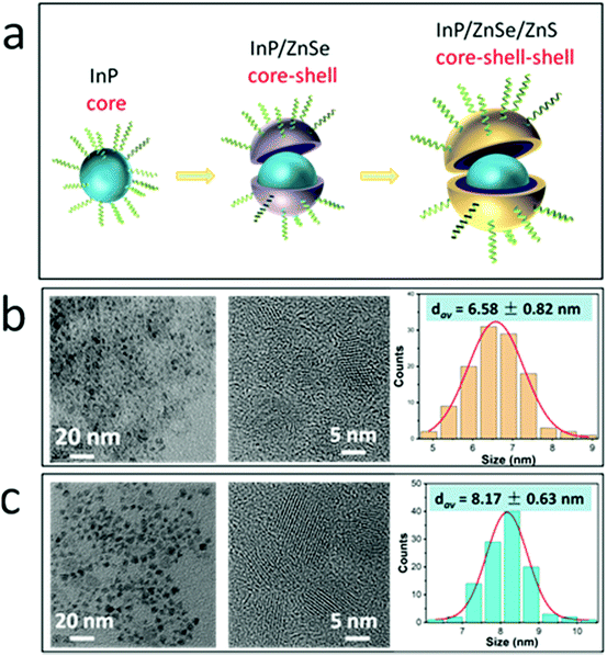
To synthesize high-quality InP-based QDs, most effects have been devoted to reducing defects in the deep in-gap states of InP QDs and oxidative defects. In this work, we prepared InP/ZnSe/ZnS QDs following the reported literature.33 Compared to the standard InP/ZnSe/ZnS QDs, the reference sample experienced in situ etching of the oxide surface of the InP core using hydrofluoric acid (HF), at the same time as the formation of the ZnSe interlayer, followed by the passivation of ZnS shell. Finally, InP/ZnSe/ZnS HF-treated QDs were successfully synthesized, as shown in Fig. 1(a). For simplicity, the prepared InP QDs without and with surface fluorination treatment are expressed as InP QDs and InP-HF QDs, respectively. The size of InP core is about 3 nm in this work, which is gradually grown to the average size of the 6.58 and 8.17 nm for InP and InP-HF QDs, respectively, as shown in Fig. 1(b) and (c).The absorption and PL spectra of InP QDs without and with surface fluorination treatment are shown in Fig. 2(a), which indicates that HF etching makes a small impact on optical absorption and PL peaks. A time-resolved photoluminescence (TRPL) test was employed to monitor the effects of HF treatment on the energy transfer. The fluorescence lifetime of InP QDs is 85 ns, which decreases to 68 ns for InP-HF QDs. Shell coating would introduce defects in the core–shell interfaces due to lattice mismatch, which could be perfected after HF treatment by reducing defects. The fluorescence lifetime is related to radiative and non-radiative decay rates. The introduction of surface fluorination influences the non-radiative energy transfer process, resulting in the 20% fluorescence lifetime decrease of InP-HF QDs.
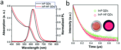 | ||
| Fig. 2 (a) PL and absorption spectra of InP and InP-HF QDs. (b) TRPL of InP and InP-HF QDs. The insets are photos of the InP-HF QD film (left) and of that excited by UV light of 365 nm (right). | ||
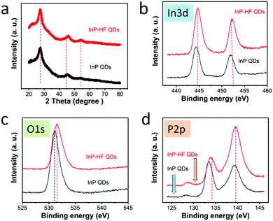
According to the XRD pattern, the three characteristic diffraction peaks are located at 27.0, 45.6 and 54.6, corresponding to the (111), (220) and (311) planes of the zinc blende phase of InP (PDF#32-0452), respectively.34,35 For InP-HF QDs, the XRD diffraction peaks shift to 27.4, 46.2 and 54.4, respectively, indicating the increase of the diameter of QDs. This result is consistent with the increased size of InP-HF QDs shown in TEM images above. To investigate the chemical change caused by the HF treatment, XPS spectra was detected as shown in Fig. 3. In the 3d XPS peak of InP QDs located at 444.4 and 451.9 eV, which shifted to 444.8 and 452.3 eV for InP-HF QDs, respectively. This indicates the formation of In–F bonds, bringing the detachment of organic carboxylate ligands on the surface of In.36 The position of P 2p peaks are around 133.6 and 139.3 eV for InP QDs, and shifted to 134.0 and 139.5 eV, respectively, after HF treatments. The XPS O 1s spectra of pristine InP QDs peaked at 531.2 eV, the tail at the longer wavelength is associated with hydroxide-like In(OH)3 or InOOH.37,38 After surface HF modification, InPOx and carboxylate are removed, corresponding to the decreased P 2p peak (133.6 eV) and P–O bond. HF treatment of InP QDs creates new In–P chemical bonds and detachment of the organic carboxylate ligands.
The experimental configuration is shown in Fig. 4(a). An 808 nm fiber-coupled diode laser was used as a pumping source. After a lens assembly with a ratio of 1![[thin space (1/6-em)]](https://www.rsc.org/images/entities/char_2009.gif) :
:![[thin space (1/6-em)]](https://www.rsc.org/images/entities/char_2009.gif) 2, the pump laser was focused into the Nd
2, the pump laser was focused into the Nd![[thin space (1/6-em)]](https://www.rsc.org/images/entities/char_2009.gif) :
:![[thin space (1/6-em)]](https://www.rsc.org/images/entities/char_2009.gif) YVO4 crystal. The thin film of InP-based QD SA was placed as close as possible to M2 to obtain a large power intensity. The output power characteristic as a function of incident pulse power is shown in Fig. 4(b). It can be seen that InP-HF QDs obtained satisfying output power of as high as 2.5 W. A stable passively Q-switched laser was achieved when the pump power exceeded 1 W, clarifying a low threshold. The complete evolution of pulse repetition rates (RPP) and FWHM with incident pump powers is shown in Fig. 4(c). As the pump poser increased, the repetition rate increased from 225 to 666 KHz and the pulse width varied from 970 ns to 178 ns. The maximum single pulse power reached up to 33 W (single peak energy is 3.2 μJ). Obviously, InP QDs showed unsatisfactory and unstable performance (see the ESI†). The results revealed that InP-HF QDs with surface modification possess promising potential in generating near-infrared laser pulses with high power and high pulse energy.
YVO4 crystal. The thin film of InP-based QD SA was placed as close as possible to M2 to obtain a large power intensity. The output power characteristic as a function of incident pulse power is shown in Fig. 4(b). It can be seen that InP-HF QDs obtained satisfying output power of as high as 2.5 W. A stable passively Q-switched laser was achieved when the pump power exceeded 1 W, clarifying a low threshold. The complete evolution of pulse repetition rates (RPP) and FWHM with incident pump powers is shown in Fig. 4(c). As the pump poser increased, the repetition rate increased from 225 to 666 KHz and the pulse width varied from 970 ns to 178 ns. The maximum single pulse power reached up to 33 W (single peak energy is 3.2 μJ). Obviously, InP QDs showed unsatisfactory and unstable performance (see the ESI†). The results revealed that InP-HF QDs with surface modification possess promising potential in generating near-infrared laser pulses with high power and high pulse energy.
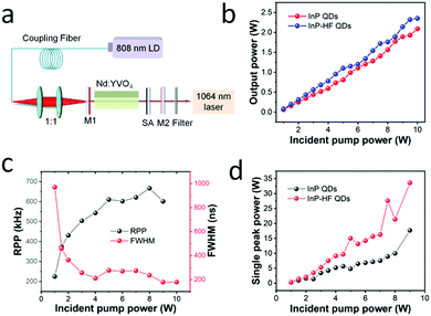 | ||
| Fig. 4 (a) A schematic of the passive Q-switching Nd:YVO4 laser. (b) The average output power. (c) Pulse repetition rate. (d) Single pulse energy. | ||
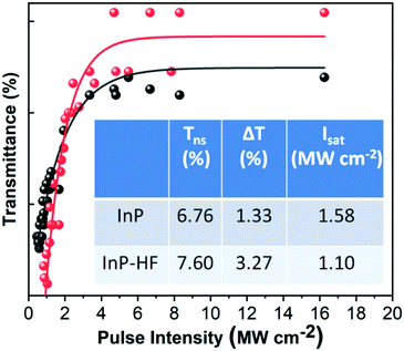
The nonlinear optical transmission was measured using the two-detector method. The laser source is 1064 nm and has 10 mJ single pulse energy, 8 ns pulse duration and 1 Hz repetition rate. The obtained experimental results are denoted with red and black balls, and the fitted curve is indicated by a solid red and black line, respectively. Here, the fitted curve is constructed using the equation T(I) = 1 − ΔT × exp(−I/Isat) − Tns, where T(I) is the transmission, ΔT is the modulation depth, I is the input intensity, Isat is the saturation intensity, and Tns is the non-saturable loss.39 From the curve, the modulation depth and the saturable intensity of InP QDs are determined to be 1.33% and 1.58 MW cm−2, respectively. After surface fluorination treatment, the obtained InP-HF QDs exhibit modulation depth and saturable intensity of 3.27% and 1.10 MW cm−2, respectively. The nonlinear optical transmission data of InP and InP-HF QDs are summarized in the table inset in Fig. 5. Good Q-switching generally has excellent quality, such as large modulation depth, perfect saturate intensity and tiny unsaturable loss. Low saturable intensity leads to decreased numbers of reversed populations and energy loss, while the high saturable intensity would result in a retarded Q-switching speed and inferior Q modulation effect. Comparatively, HF treated InP QDs as a saturable absorber have good nonlinear optical properties and have great potential in the generation of ultrafast laser pulses.
Typical pulse trains recorded at different pump powers are shown in Fig. 6. The emission spectrum and conversion efficiency of a Q-switched laser without a saturable absorber have been added in the ESI† (Fig. S1). The pulse repetition rate is 225 KHz at the threshold with a record output power of about 80 mW. As the output power increases to 8 W, the pulse repetition rate increases to 666 kHz. In the meantime, the pulse widths vary from 1 μs to 236 ns. The groups of pulse trains indicate the corresponding single pulse duration at different pump powers, and a higher pumper power generates more pulses and narrower pulse duration. For original InP QDs SA, it showed unstable Q-switching operation at higher incident pump power, indicating poor nonlinear optical responses (see the ESI†).
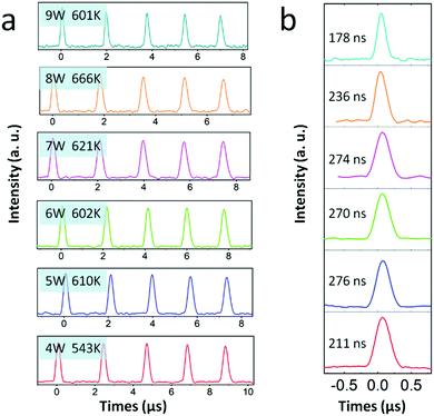 | ||
| Fig. 6 (a) The pulse train of InP-HF QDs at different time scales. (b) Single pulse duration under different pump powers. | ||
4. Conclusions
In summary, InP-HF QDs with surface fluorination treatment exhibited superior nonlinear optical absorption properties compared with original InP QDs. The reason behind these superior properties was the decreased defects at interfaces of the core–shell structure. Therefore, InP-HF QDs can be considered as a credible choice for a saturable absorber with a large modulation depth and small saturable intensity. The features of such InP-based QDs make it possible to induce passive Q-switching and mode-locking, generating short-to-ultrashort laser pulses with a higher energy and pulse repetition rate, which are applied in optical fiber communication, fiber sensing and medical diagnosis.Author contributions
Xiao Zhang and Yajun Lou contributed equally to this work. The manuscript was written through contributions of all authors. All authors have given approval to the final version of the manuscript.Conflicts of interest
There are no conflicts to declare.Acknowledgements
This research was supported by the Guangdong International Cooperation Project (No. 2019A050510002), the Research Fund of Guangdong-Hong Kong-Macao Joint Laboratory for Intelligent Micro-Nano Optoelectronic Technology (No. 2020B1212030010), and the Open Fund of Guangdong Provincial Key Laboratory of Information Photonics Technology (Guangdong University of Technology) (No. GKPT20-09).References
- P. Grelu and N. Akhmediev, Nat. Photonics, 2012, 6, 84–92 CrossRef CAS.
- S. Barbieri, P. Gellie, G. Santarelli, L. Ding, W. Maineult, C. Sirtori, R. Colombelli, H. Beere and D. Ritchie, Nat. Photonics, 2010, 4, 636–640 CrossRef CAS.
- M. E. Fermann and I. Hartl, Nat. Photonics, 2013, 7, 868 CrossRef CAS.
- N. Nishizawa, J. Appl. Phys., 2014, 53, 090101 CrossRef CAS.
- J. Philipps, T. Töpfer, H. Ebendorff-Heidepriem, D. Ehrt, R. Sauerbrey and N. Borrelli, Appl. Phys. B: Lasers Opt., 2001, 72, 175 CrossRef CAS.
- A. A. Lagatsky, C. G. Leburna, C. T. A. Browna, W. Sibbetta, S. A. Zolotovskayab and E. U. Rafailov, Prog. Quantum Electron., 2010, 34, 1–45 CrossRef.
- V. G. Savitski, P. J. Schlosser, J. E. Hastie, A. B. Krysa, J. S. Roberts and M. D. Dawson, IEEE Photonics Technol. Lett., 2010, 22, 209–211 CAS.
- Y. Shi, H. Long, S. Liu, Y. H. Tsang and Q. Wen, J. Mater. Chem. C, 2018, 6, 12638 RSC.
- H. Long, Y. Shi, Q. Wen and Y. H. Tsang, J. Mater. Chem. C, 2019, 7, 5937 RSC.
- Y. Jhon, J. Koo, B. Anasori, M. Seo, J. H. Lee, Y. Gogotsi and Y. M. Jhon, Adv. Mater., 2017, 29, 1702496 CrossRef PubMed.
- M. B. Hisyam, M. F. Rusdi, A. A. Latiff and S. W. Harun, Chin. Opt. Lett., 2016, 14, 081404 CrossRef.
- L. Yun, Y. Qiu, C. Yang, J. Xing, K. Yu, X. Xu and W. Wei, Photonics Res., 2018, 6, 1028 CrossRef CAS.
- N. M. Radzi, A. A. Latif, M. F. Ismail, J. Y. C. Liew, E. Wang, H. K. Lee, N. Tamcheck, N. A. Awang, F. Ahmad, M. K. Halimah and H. Ahmad, Results Phys., 2020, 16, 103123 CrossRef.
- D. J. Lewis, P. Kevin, O. Bakr, C. A. Muryn, M. A. Malik and P. O’Brien, Inorg. Chem. Front., 2014, 1, 577 RSC.
- H. Long, L. Tao, C. Y. Tang, B. Zhou, Y. Zhao, L. Zeng, S. F. Yu, S. P. Lau, Y. Chai and Y. H. Tsang, Nanoscale, 2015, 7, 17771 RSC.
- Y. Xu, Z. Wang, Z. Guo, H. Huang, Q. Xiao, H. Zhang and X. F. Yu, Adv. Opt. Mater., 2016, 4, 1223 CrossRef CAS.
- M. E. Fermann and I. Hartl, Nat. Photonics, 2013, 7, 868 CrossRef CAS.
- C. Xu and F. W. Wise, Nat. Photonics, 2013, 7, 875 CrossRef CAS PubMed.
- Y. Chen, Y. Lin, Y. Zou, Z. Luo and Y. Huang, J. Light Technol., 2012, 20, 9940 CAS.
- Z. Wang, C. Li, J. Ye, Z. Wang and Y. G. Liu, Laser Phys. Lett., 2019, 16, 025103 CrossRef CAS.
- D. Zherebetskyy, Y. Zhang, M. Salmeron and L.-W. Wang, J. Phys. Chem. Lett., 2015, 6, 4711–4716 CrossRef CAS PubMed.
- O. Voznyy, J. Phys. Chem. C, 2011, 115, 15927–15932 CrossRef CAS.
- P. Reiss, M. Carrière, C. Lincheneau, L. Vaure and S. Tamang, Chem. Rev., 2016, 116, 10731–10819 CrossRef CAS PubMed.
- A. Cros-Gagneux, F. Delpech, C. Nayral, A. Cornejo, Y. Coppel and B. Chaudret, J. Am. Chem. Soc., 2010, 132, 18147–18157 CrossRef CAS PubMed.
- H. Virieux, M. Le Troedec, A. Cros-Gagneux, W.-S. Ojo, F. Delpech, C. Nayral, H. Martinez and B. Chaudret, J. Am. Chem. Soc., 2012, 134, 19701–19708 CrossRef CAS PubMed.
- S. Tamang, C. Lincheneau, Y. Hermans, S. Jeong and P. Reiss, Chem. Mater., 2016, 28, 2491–2506 CrossRef CAS.
- P. Reiss, M. Carriere, C. Lincheneau, L. Vaure and S. Tamang, Chem. Rev., 2016, 116, 10731–10819 CrossRef CAS PubMed.
- M. D. Tessier, D. Dupong, K. D. Nolf, J. D. Roo and Z. Hens, Chem. Mater., 2015, 27, 4893–4898 CrossRef CAS.
- L. S. Jennifer, M. H. William, M. Amrit Venkatesh, J. R. Aaron, T. S. Gerald and M. C. Brandi, Chem. Mater., 2018, 30, 6377–6388 CrossRef.
- S. Adam, C. McGinley, T. Möller, D. V. Talapin, H. Borchert, M. Haase and H. Weller, Eur. Phys. J. D, 2003, 24, 373–376 CrossRef CAS.
- S. Adam, D. V. Talapin, H. Borchert, A. Lobo, C. McGinley, A. R. B. de Castro, M. Haase, H. Weller and T. Möller, J. Chem. Phys., 2005, 123, 084706 CrossRef CAS PubMed.
- T. Kim, D. Zherebetskyy, Y. Bekenstein, M. Hwan Oh, L. Wang, E. Jang and A. P. Alivisatos, ACS Nano, 2018, 12, 11529–11540 CrossRef CAS PubMed.
- Y. Won, O. Cho, T. Kim, D. Chung, T. Kim, H. Chung, H. Jang, J. Lee, D. Kim and E. Jang, Nature, 2019, 575, 634–638 CrossRef CAS PubMed.
- Y. Pu, H. Fan, J. Chang, Y. Chen and S. Tseng, J. Phys. Chem. Lett., 2021, 12, 7194–7200 CrossRef CAS PubMed.
- H. Zhang, X. Ma, Q. Lin, Z. Zeng, H. Wang, L. Li, H. Shen, Y. Jia and Z. Du, J. Phys. Chem. Lett., 2020, 11, 960–967 CrossRef CAS PubMed.
- M. O. Figueiredo, T. P. da Silva, D. de Oliveira and D. Rosa, Minerals, 2012, 2, 426–434 CrossRef CAS.
- D. Zherebetskyy, M. Scheele, Y. Zhang, N. Bronstein, C. Thompson, D. Britt, M. Salmeron, P. Alivisatos and L.-W. Wang, Science, 2014, 344, 1380–1384 CrossRef CAS PubMed.
- D. Kim, D.-H. Kim, J.-H. Lee and J. C. Grossman, Phys. Rev. Lett., 2013, 110, 196802 CrossRef PubMed.
- X. Wang, Y. G. Wang, D. Mao, L. Li and Z. Chen, Mater. Express, 2017, 7, 2913–2921 CrossRef CAS.
Footnote |
| † Electronic supplementary information (ESI) available. See DOI: https://doi.org/10.1039/d2ma00442a |
| This journal is © The Royal Society of Chemistry 2022 |

