
 Open Access Article
 This Open Access Article is licensed under a Creative Commons Attribution-Non Commercial 3.0 Unported Licence
High-performance supercapacitors based on amorphous carbon derived from natural Ramulus mori†
Yaping
Xu‡
a,
Renfeng
Tan‡
a,
Jinggao
Wu
b and
Jing
Huang
 *a
*a
aState Key Laboratory of Silkworm Genome Biology, Key Laboratory Of Sericultural Biology and Genetic Breeding, Ministry of Agriculture and Rural Affairs, College of Sericulture, Textile and Biomass Sciences, Southwest University, Chongqing 400715, P. R. China. E-mail: hj41012@163.com
bKey Laboratory of Rare Earth Optoelectronic Materials & Devices, College of Chemistry and Materials Engineering, Huaihua University, Huaihua 418000, P. R. China
First published on 22nd July 2022
Abstract
Using biomass waste as a supercapacitor material has been one of the most widely used methods owing to its high performance, low cost and sustainable green economy. Herein, we employ Ramulus mori, a silkworm industry waste, by low-cost pyrolysis and chemical activation methods to produce high-efficiency, high-power and high-energy supercapacitors. The as-prepared architectures with a large number of hierarchical pores and high specific surface areas exhibit a high specific capacitance of ∼796 F g−1 at 1 A g−1, and the retention rate can reach 93.6% even after 10![[thin space (1/6-em)]](https://www.rsc.org/images/entities/char_2009.gif) 000 cycles at 10 A g−1. The assembled symmetrical device has a high energy density of ∼59 W h kg−1 at 1.2 kW kg−1, which paves the way for the development of green electrode materials with promising applications.
000 cycles at 10 A g−1. The assembled symmetrical device has a high energy density of ∼59 W h kg−1 at 1.2 kW kg−1, which paves the way for the development of green electrode materials with promising applications.
1. Introduction
Owing to the inevitable depletion of non-renewable energy and the increasingly serious global environmental pollution problem, developing efficient energy storage and conversion systems is urgently needed to fulfill the demand for renewable energy and clean energy sources.1–3 Among the energy storage devices, supercapacitors (SCs) are one of the most extensively applied devices owing to their superior power density, rapid charge/discharge potency, longer operating time, environmental sustainability and safety features.4–6 SCs have been widely used in new energy vehicles, smart grids, urban transportation and other fields. However, the wide application of SCs is still limited due to their relatively low energy density.7,8The key to the performance of supercapacitors lies in electrode materials, including carbonaceous materials, transition-metal based materials (e.g., oxides, nitrides and sulfides) and conducting polymers.9–12 Carbon materials usually have a high specific surface area, good conductivity and chemical stability, abundant reserve, and are easy to produce and process, and non-toxic.13–16 There are currently many issues associated with the combustion of fossil fuels and waste generation, and sustainable industrial growth is much focused on.17 Biomass is a readily available, inexpensive, easy to modify, environmentally friendly, and renewable resource.18–20 Usually, chemical activation with alkali hydroxides such as KOH, NaOH and LiOH or acidic compounds such as H3PO4 and ZnCl2 is an effective method to fabricate porous activated carbon materials.21,22 These advantages, together with the high carbon content of biomass, make it an attractive raw material for the preparation of advanced functional carbon materials in the field of supercapacitors.23–26
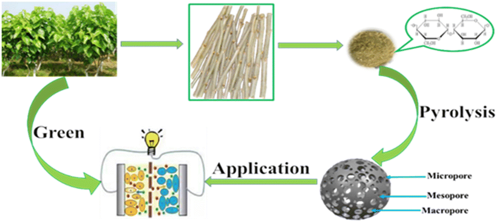
Mulberry is an environmentally friendly, widespread, and versatile plant. At present, mulberry biomass has been used for extracting active ingredients for medical research such as rutin, quercetin, 1-deoxynojirimycin, N-methyl-1-deoxynojirimycin, 1,4-dideoxy-1,4-imino-D-arabinitol, β-sitosterol, stigmasterol, β-sitolsterolβ-D-glucoside and γ-aminobutyric acid with high antibacterial, anticoagulation, hypotensive, hypolipemic, hyperglycemic, antitumor, antisenescence, antifilarial, and antiulcerative activities.27–29 Large quantities of mulberry-based by-products of extraction residues are generated during the process, which could be envisaged for value-added secondary-utilization as green energy storage materials.30,31 The total production of Ramulus mori in 2018 in China is in the scope of 2.844–3.555 million tons.32 A large share of Ramulus mori is consumed by agro-industries where the disposal of waste Ramulus mori is a great issue. In this work, we report a novel bio-inspired hierarchical nanoporous carbon employing the mulberry-based by product (Ramulus mori) as a raw material by a facile two-step method involving carbonization and activation annealing (Scheme 1). The performance of the electrode and the supercapacitor based on Ramulus mori derived carbonaceous materials and the structure–activity relationship have been investigated in detail.
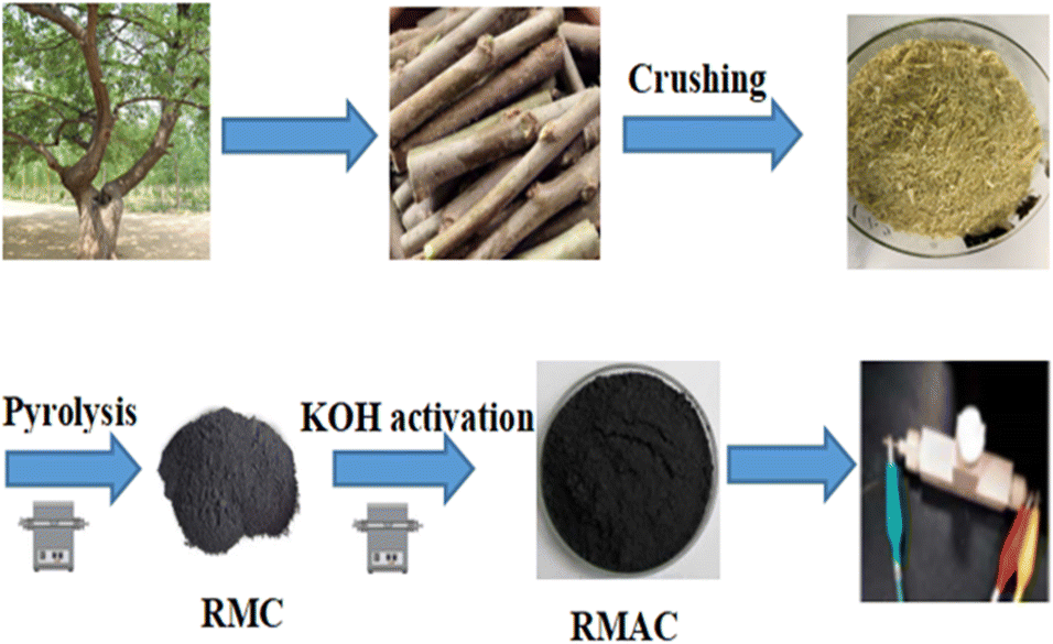 | ||
| Scheme 1 Schematic illustration of the synthesis strategy of the RMAC composites. | ||
2. Experimental section
2.1 Materials and methods
:1.5 were thoroughly ground in an agate mortar. After grinding, the mixture was further heated to 700 °C according to the pyrolysis process similar to RMC in the tube furnace. Finally, the obtained carbon was named RMAC-4. For comparison, the different mass ratios of RMC and KOH (2:1, 3:2, 1:1, and 1:2) were also investigated by the above process. The samples were denoted as RMAC-1, RMAC-2, RMAC-3 and RMAC-5. In addition, RMAC-6, RMAC-7 and RMAC-8 were prepared at 600, 800 and 900 °C in accordance with the procedure similar to RMAC-4. In the whole process, all carbonized samples were neutralized with dilute HCl and washed with deionized water, and then dried at 80 °C for 12 h.
2.2 Characterization
The XRD patterns were characterized using powder X-ray diffraction (Shimadzu XRD7000). The surface morphology and structure of samples were obtained through scanning electron microscopy (FESEM, JSM-7800F) and transmission electron microscopy (TEM, JEOL 2100). Nitrogen sorption isotherms were recorded by means of an Autosorb-1 (Quantachrome Instruments). The specific surface area was reckoned through the Brunauer–Emmett–Teller (BET) method. The distributions of the pore size and the pore volume were confirmed from the adsorption branch isotherms through the density functional theory (DFT) method. And then, the total pore volume (Vt) was reckoned based on the amount adsorbed at a relative pressure P/P0 of 0.990. The volume (Vmic) and surface area (Smic) of the micropore were analysed on the basis of the t-plot theory. Raman spectra were obtained with a Jobin–Yvon HR 800 spectrometer. X-Ray photoelectron spectroscopy (XPS) measurements were carried out on a Thermo Fisher Scientific (Escalab 250xi, USA). Fourier transform infrared (FT-IR) spectra were acquired using a Thermo Scientific Nicolet iS 50 spectrometer.2.3 Electrochemical measurements
For the two-electrode system, a homogeneous slurry of the electroactive material, polytetrafluoroethylene (PTFE), and acetylene black with a weight ratio of 80:10:10 in ethanol was formed and pasted to the nickel foam current collector (1 cm × 1 cm), then vacuum dried at 80 °C for 12 h. The loading of the active material for each working electrode was measured to be ∼3 mg cm−2. And then, a glass-fiber filter paper (Waterman, GF/B) as a separator and 1 M KOH aqueous solution as the electrolyte were used to assemble a test cell. For the three-electrode system, the working electrode was prepared through the dispersion of active carbon in mixed solution of Nafion and ethanol (1:20) dripping on the glassy carbon electrode. Platinum foil and Hg/HgO were used as the counter and reference electrodes, respectively. Electrochemical characterization was carried out on an electrochemical workstation (Shanghai Chenhua Instrument Co. Ltd, China).
For the two-electrode system, the gravimetric specific capacitance of a single electrode is calculated by the following equation:
| Csp = 2I × Δt/m × ΔV | (1) |
For the three-electrode system, the gravimetric specific capacitance can be calculated by the following equation:
| Csp = I × Δt/m × ΔV | (2) |
The energy density E (W h kg−1) and the power density P (W kg−1) are calculated by the following equations:
| E = CspV2/(2 × 3.6) | (3) |
| P = 3600 E/Δt | (4) |
3. Results and discussion
3.1 Material characterization
The characteristics of morphology and structure are displayed by FESEM (scanning electron microscopy) images. Fig. 1a and Fig. S1 (ESI†) for RMAC-4 indicate a large number of pores in a variety of sizes, from several tens to several hundreds of nanometers, which form an interconnected carbonaceous framework of potassium through hydroxide (KOH) etching. The activation process actually involves the creation of more pores, producing a highly porous solid phase for the carbonmaterials.33 The specialized structure would be conducive for the infiltration of the electrolyte from the side of the electrode and further additional active sites are exposed to faradaic reaction, which contribute to the electrochemical performance of the carbonaceous material.34–36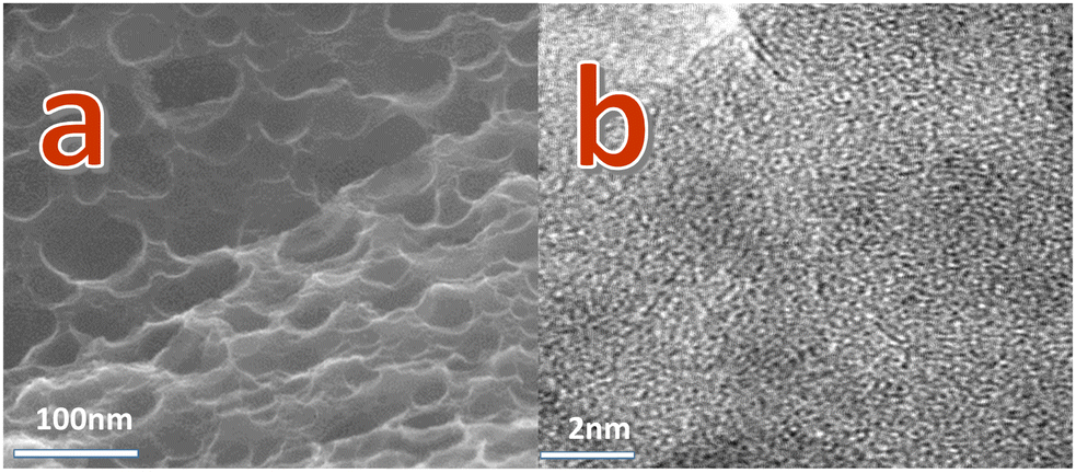 | ||
| Fig. 1 (a) FESEM images of RMAC-4; (b) TEM images of RMAC-4. | ||
For a detailed microstructural and morphological investigation of the heterostructured composite, HR-TEM was employed. The high-magnification TEM image (Fig. 1b) for RMAC-4 manifests the highly fluffy surface structure featuring abundant pores and further illustrates the ribbon graphite texture, which confirms the partial graphitization of RMAC-4. A porous structure is favourable, especially for electrolyte penetration. Above all, the whole synthesis process could be expanded to several grams repeatably, while maintaining the specific surface area and pore size distribution.37 Based on this, this simple, easy and ponderable synthetic process is therefore highly beneficial in practical usage.
To assess the composition of the prepared samples qualitatively, FT-IR spectroscopy is carried out. As for FT-IR spectrum of RMAC-4 and RMC (Fig. S2, ESI†), the shoulder peak at 1636 cm−1 and the broad peak at 3482 cm−1 indicate water molecules in the interlayer spaces, and the stretching vibrational mode of the hydroxyl functional groups, respectively. The peaks at 2920 and 1362 cm−1 are ascribed to the VC–H and VC–O vibration modes, respectively.38 An intense peak positioned at 2342 cm−1 is produced mainly owing to the introduction of heteroatoms in the carbon structure.39 The signal located at 1120 cm−1 is attributed to C–O–C (symmetric angular deformation of ethers).40
The XRD patterns of RMAC-4 and RMC are shown in Fig. 2a for comparison. The characteristic XRD peaks of RMAC-4 obtained at the 2θ values of 21.58° and 43.12° are indexed to the (002) and (100) planes of graphitic carbon layers, respectively, demonstrating partially graphitic structures due to carbonization.41 Apparently, a broadened diffraction peak located at 21.58° corresponds to the (002) plane, which confirms an amorphous structure and the presence of abundant amorphous defect sites.42 This combination of all pore size regimes in RMAC-4 promises an ultrafast ion transfer.
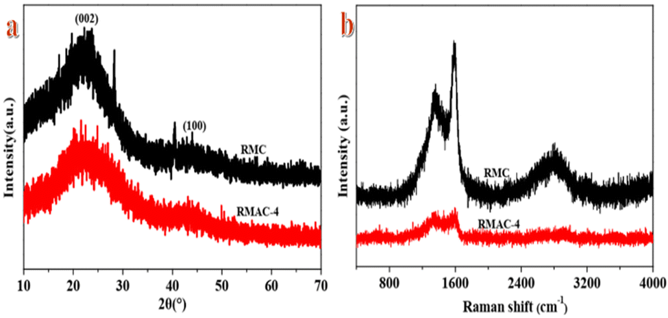 | ||
| Fig. 2 (a) XRD patterns of RMC and RMAC-4 and (b) Raman spectrum of RMC and RMAC-4. | ||
To evaluate the structural features and nature of phase formation in the composite electrode, Raman spectra are recorded. As usual, Raman spectra (Fig. 2b) of RMAC-4 and RMC show typical vibrational peaks at around 1350 and 1603 cm−1, representing the D-band and G-band, respectively.43 The D-band is related to carbon with sp3 hybridization, which indicates amorphous carbon or defects. The G-band is associated with sp2 hybridized carbons, which confirms graphitic carbon.44 The ratio of intensities of the D-band and G-band (ID/IG) is generally utilized to evaluate the degree of crystallization or defect density of carbon materials.45,46 The ratio of ID/IG is 0.913 for RMAC-4 and 0.725 for RMC, revealing that RMAC-4 presents much structural disorder by virtue of the activation of KOH and further could enhance the electrochemical performance.47
Another factor that plays an important role in electrochemical performance is the surface area and porosity of the materials. N2 adsorption/desorption measurements are performed to characterize the porosity of RMAC samples and RMC. The BET surface areas for RMAC-4 and RMC are found to be 645.711 and 7.191 m2 g−1, respectively (Table 1), which are lower than the previous reports.23–26 Whereas, the RMAC-4 nanocomposite has shown a larger pore volume of 0.33 cm−3 g−1 than that of RMC with a pore volume of 0.016 cm−3 g−1, which is ascribed to the activation with the porogens. The activation of KOH could contribute to the formation of the porous carbon further leading to plentiful pores generated on the surface of the carbon material with the macropores and mesopores remaining. According to the IUPAC classification, the N2 adsorption–desorption curves (Fig. S3, ESI†) for RMAC-4 present type-I isotherm with H4 hysteresis as per the Brunauer classification, which imply the presence of mesopores with a pore diameter of ∼3.186 nm. The weak uptake trend at a relative pressure above 1.0 also manifests the presence of macropores, and further indicates the coexistence of the hierarchical micro-/meso-/macroporous structure for RMAC-4.48 The pore size distribution (Fig. S4, ESI†) shows the main peaks in the range of 4–30 nm, which indicate a relatively ordered regular pore size distribution at the nanometer scale. An ordered regular pore frame construction is evident for ion diffusion/transport, and high porosity can contribute to electrolyte penetration and offer more electrochemically active sites.49 The hierarchical structure can reduce the diffusion resistance, and improve the mass transport in the electrolyte, as well as expose more active sites, which is conducive to the enhancement of the electrochemical performance.50 At the same time, the activation temperature also affects textural properties, such as (a BET surface area of 645.71 vs. 483.42 m2 g−1; a pore volume of 0.33 vs. 0.267 cm−3 g−1; an average pore size of 3.186 vs. 2.183 nm; RMAC-6 vs. RMAC-8, 600 vs. 900 °C). With the increase of the activation temperature from 600 °C to 700 °C, the structure parameters indicate the same tendency. However, increasing the activation temperature to 900 °C would contribute to the collapse of the pores, and further unfavourably results in the decrease of the textural properties.
| Sample | S BET | V tot | S mi | S me | S ma | V mi | V me | V ma |
|---|---|---|---|---|---|---|---|---|
| a S BET: BET surface area. b V tot: total volume. c S mi: micropore surface area. d S me: mesopore surface area. e S ma: macropore surface area. f V mi: micropore volume. g V me: mesopore volume. h V ma: macropore volume. | ||||||||
| RMC | 7.191 | 0.017 | 1.352 | 4.87 | 0.969 | 0.002 | 0.012 | 0.003 |
| RMAC-1 | 423.15 | 0.236 | 103.32 | 205.12 | 114.71 | 0.082 | 0.103 | 0.051 |
| RMAC-2 | 721.36 | 0.307 | 116.23 | 462.18 | 142.95 | 0.102 | 0.175 | 0.03 |
| RMAC-3 | 525.34 | 0.315 | 103.25 | 364.57 | 57.52 | 0.086 | 0.201 | 0.028 |
| RMAC-4 | 645.711 | 0.332 | 116.45 | 473.16 | 56.101 | 0.092 | 0.216 | 0.024 |
| RMAC-5 | 756.23 | 0.248 | 136.24 | 503.17 | 117.301 | 0.012 | 0.185 | 0.051 |
| RMAC-6 | 415.62 | 0.284 | 86.42 | 301.68 | 27.52 | 0.015 | 0.204 | 0.065 |
| RMAC-7 | 531.84 | 0.139 | 103.42 | 352.46 | 75.96 | 0.01 | 0.082 | 0.047 |
| RMAC-8 | 483.42 | 0.267 | 136.24 | 308.42 | 38.76 | 0.028 | 0.166 | 0.073 |
The atomic valence states and elemental composition of the composite are measured by XPS, as shown in Fig. 3. Nitrogen, oxygen, phosphorus and sulfur elements are introduced into the carbon skeleton via the pyrolysis strategy. C1s spectra (Fig. 3b) of RMAC-4 after deconvolution indicates a peak at 285.3 eV attributed to sp3 carbon in the C–S bond.51 The N1s core level spectra (Fig. 3c) of RMAC-4 are deconvoluted into three components as quaternary-N (NQ, 402.2 eV), amide/amines or nitrile N (NC, 399.4 eV) and oxidized-N (NX, 406.5 eV).52 The existence of N–O in the carbon graphitic plane effectively reduces the electronic transfer resistance of RMAC-4. O1s (Fig. 3d) spectra appear in the form of P![[double bond, length as m-dash]](https://www.rsc.org/images/entities/char_e001.gif) O (531.9 eV) and P–O–P/P–O–C (533.2 eV), respectively. The hydrophilicity of the O-containing groups in RMAC-4 could be conducive to the wettability of the electrolyte interface, which results in the enhancement of the electrochemical performance.53 The P2p spectra shown in Fig. 3e display that three peaks for 2p3/2 at 131.4 eV, 134.4 eV, and 138 eV, which could be assigned to C–P species, pyrophosphate/polyphosphate (PP) and monophosphate/metaphosphate (MP) groups, respectively.54 The S2p XPS spectrum (Fig. 1f) is deconvoluted to three peaks at 161.8 eV, 164.2 eV and 167.6 eV for S2p3/2 (S1, CS) and S2p1/2 (S2, C–S) as well as oxidized sulfur species, which confirm the doping of the RMAC-4 network by sulphur46.46,55 Synergistic effect originating from the multiple doping of N, O, P and S are conducive to the electrochemical reactions. On account of RMC, the presence of C, N, O, P, and S has also been confirmed by the XPS spectrum (Fig. S4a, ESI†). The C1s spectrum (Fig. S4b, ESI†) is deconvoluted into three peaks representing CC (284.24 eV), S-sp3C (284.85 eV), C–O (285.77 eV) and CO (287.53 eV) groups.50 The N 1s spectrum (Fig. S4c, ESI†) indicates that there are four forms of N, namely, N-6 (397.5 eV), N–C (398.3 eV), N-5 (399.3 eV) and N–Q (402.1 eV).51 The O1s spectrum (Fig. S4d, ESI†) is fitted by two peaks, located at 532.2 and 532.8 eV, which could belong to PO and P–O–P/P–O–C groups.52 By fitting the P2p spectra (Fig. S4e, ESI†), three main peaks located at 131.3 eV, 133.8 eV and 135.1 eV are clearly identified, which indicate the existence of C–P species, pyrophosphate/polyphosphate (PP) and monophosphate/metaphosphate (MP) bonds.53 The S2p (Fig. S4f, ESI†) peaks centered at 164.4, 168 and 172 eV C–S/CS correspond to CS, C–S and oxides of sulfur, respectively.54 Based on the XPS results, the surface chemistry of RMAC-4 and RMC has been altered owing to the activation of KOH, consistent with the FTIR spectra.
O (531.9 eV) and P–O–P/P–O–C (533.2 eV), respectively. The hydrophilicity of the O-containing groups in RMAC-4 could be conducive to the wettability of the electrolyte interface, which results in the enhancement of the electrochemical performance.53 The P2p spectra shown in Fig. 3e display that three peaks for 2p3/2 at 131.4 eV, 134.4 eV, and 138 eV, which could be assigned to C–P species, pyrophosphate/polyphosphate (PP) and monophosphate/metaphosphate (MP) groups, respectively.54 The S2p XPS spectrum (Fig. 1f) is deconvoluted to three peaks at 161.8 eV, 164.2 eV and 167.6 eV for S2p3/2 (S1, CS) and S2p1/2 (S2, C–S) as well as oxidized sulfur species, which confirm the doping of the RMAC-4 network by sulphur46.46,55 Synergistic effect originating from the multiple doping of N, O, P and S are conducive to the electrochemical reactions. On account of RMC, the presence of C, N, O, P, and S has also been confirmed by the XPS spectrum (Fig. S4a, ESI†). The C1s spectrum (Fig. S4b, ESI†) is deconvoluted into three peaks representing CC (284.24 eV), S-sp3C (284.85 eV), C–O (285.77 eV) and CO (287.53 eV) groups.50 The N 1s spectrum (Fig. S4c, ESI†) indicates that there are four forms of N, namely, N-6 (397.5 eV), N–C (398.3 eV), N-5 (399.3 eV) and N–Q (402.1 eV).51 The O1s spectrum (Fig. S4d, ESI†) is fitted by two peaks, located at 532.2 and 532.8 eV, which could belong to PO and P–O–P/P–O–C groups.52 By fitting the P2p spectra (Fig. S4e, ESI†), three main peaks located at 131.3 eV, 133.8 eV and 135.1 eV are clearly identified, which indicate the existence of C–P species, pyrophosphate/polyphosphate (PP) and monophosphate/metaphosphate (MP) bonds.53 The S2p (Fig. S4f, ESI†) peaks centered at 164.4, 168 and 172 eV C–S/CS correspond to CS, C–S and oxides of sulfur, respectively.54 Based on the XPS results, the surface chemistry of RMAC-4 and RMC has been altered owing to the activation of KOH, consistent with the FTIR spectra.
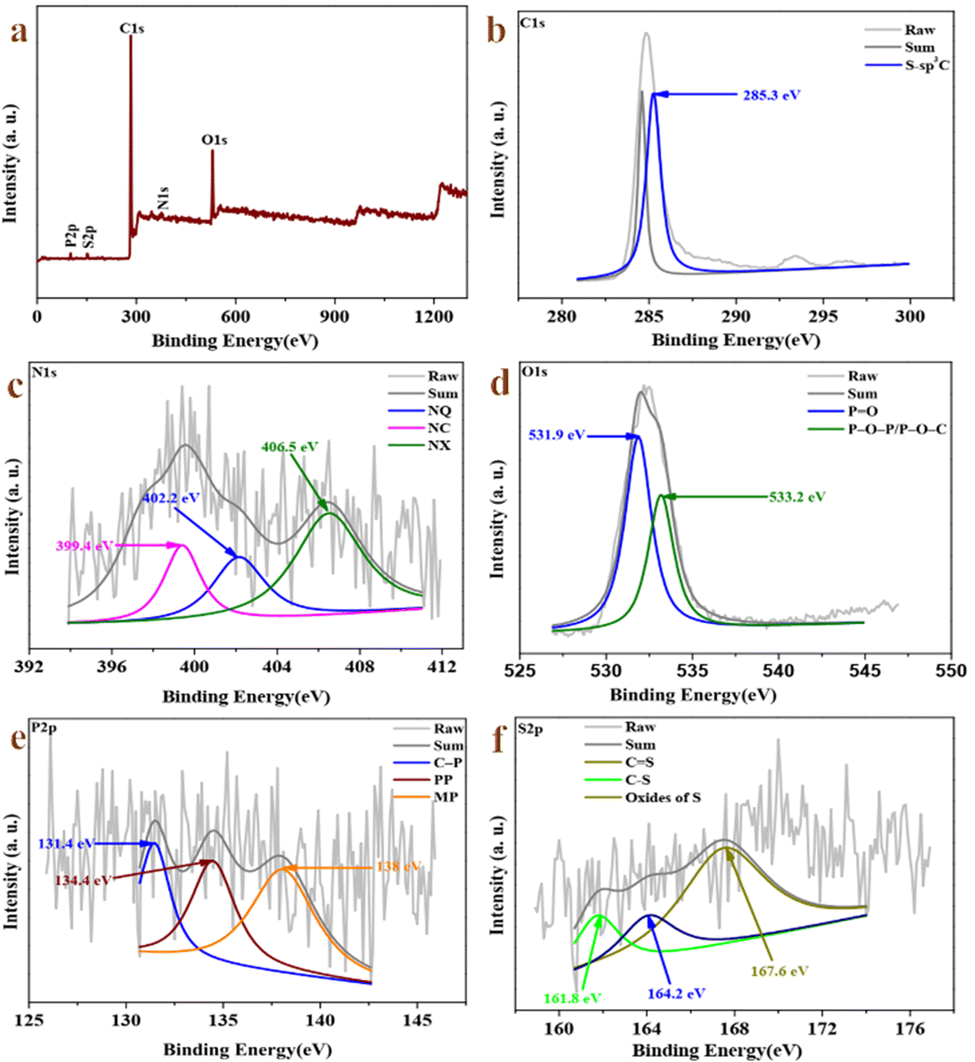 | ||
| Fig. 3 (a) XPS survey spectrum of RMAC-4, (b) high resolution C1s of RMAC-4;,(c) high resolution N1s of RMAC-4, (d) high resolution O1s of RMAC-4, (e) high resolution P2p of RMAC-4, and (f) high resolution S2p of RMAC-4. | ||
3.2 Electrochemical behaviors of the electrode
The CV curves of RMAC samples at 100 mV s−1 are shown in Fig. 4a and Fig. S5 (ESI†). All electrodes display a similar rectangular shape and a small redox peak, confirming that a typical electrical double layer capacitance (EDLC) reaction occurred on the surface of these electrodes in 1 M KOH, which is ascribed to the rapid spreading of ions along with the low diffusion resistance within the hierarchical pore structure.56 Meanwhile, all the samples have indicated a pair of reversible humps, which confirm capacitive action deriving from the electrical double layer formation and the faradaic redox reactions related to the doping with heteroatoms such as N/O/P/S-containing functional groups.57 On account of the CV area, the largest CV area for the RMAC-4 electrode has confirmed the highest capacitance, which can be ascribed to ultrafast ion transfer derived from the specific surface area and hierarchical porous configuration.58 The CV curves of the RMAC-4 (Fig. 4b) composite at different scan rates ranging from 2 to 200 mV s−1, which exhibits an almost rectangular “mirror-like” rectangular-shaped CV curve. Moreover, the CV rectangular curves of RMAC-4 have also been obtained even when the scan rate is as high as 200 mV s−1. The hierarchical pore structure ensures an ultrafast electrochemical reaction between RMAC-4 and the electrode. The very low electrochemical reaction rate is attributed to the electrolyte ions which diffuse into the interior of the pores by passing a very long distance.59 The hierarchical pore structure of the RMAC-4 electrode instead could be conducive to shorten diffusion paths. In addition, the electronic conductivity of the entire electrode is further improved by the activation of KOH, which is highly conductive after electrochemical doping.60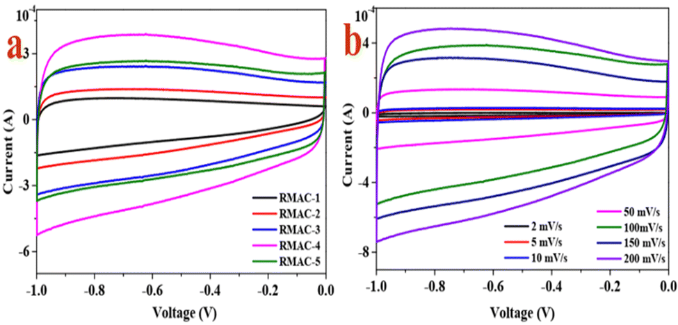 | ||
| Fig. 4 (a) CV curves of RMAC samples prepared under different ratios of precursor/KOH at 100 mV s−1 and (b) CV curves of RMAC-4 at different scan rates. | ||
The EIS tests are carried out to estimate the resistance and capacitive performances of materials in view of the kinetics information correlated to the electron/ion transport procedure and the electrochemical performance. As for the Nyquist plots (Fig. 5a), a steep line is in the low-frequency range and a semicircle is at medium frequencies, as well as intercepted with the real axis in the high-frequency region.61 The intercept of the plot and x-axis is assigned to the internal resistance (Rs), which is correlated to ohmic contact, including the intrinsic resistance of the active material, ionic resistance of the electrolyte and contact resistance of the current collector. Clearly, the Rs of RMAC-4 (1.56 Ω) at 106 kHz is small, which confirms the low charge transfer resistance. Additionally, the diameter of the semicircle refers to the interface charge transfer resistance (Rct), confirming the electron transfer derived from the electrolyte to the RMAC-4. RMAC-4 indicates a lower Rct value, which implies its higher electrical conductivity and its electron transfer dynamics. The straight line with a steeper slope in the low frequency region also manifests a superior diffusion performance of RMAC-4, which is attributed to the hollow tube and slice structure. The special configuration of RMAC-4 could refrain from the “dead volume” and further contribute to the increase of the specific surface area and a shorter channel for the diffusion of electrolyte.62 Hence, the electrochemical results suggest that the RMAC-4 matrix could contribute to the enhancement of the electronic conductivity of the electrode and improved ion diffusivity, as well as overall electrolyte wettability.
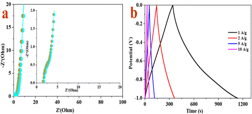 | ||
| Fig. 5 (a) Nyquist plots of RMAC-4 and (b) galvanostatic charge/discharge curves of RMAC-4 at different current densities. | ||
Fig. 5b verifies the rate capability of the RMAC-4 electrode by measuring GCD at different current densities ranging from 1 to 20 A g−1. According to the curves, an isosceles triangle shape with slight distortion and no obvious IR drop even at 20 A g−1 could be observed. Fig. 5b illustrates that the charge–discharge time decreases with the enhancement of the current density. The measured specific capacitance values at the current densities of 1–20 A g−1 are 795.94, 446.72, 289.43, 208.35, 182.34 F g−1, respectively. The lowered capacitance at higher current densities such as 182.34 F g−1 at 20 A g−1 could be attributed to the short diffusion duration at the active site of the electrode surface with a rapid rate under a high current according to the migration of K+/H+ ions in the electrolyte. Moreover, RMAC-4 with a low specific surface (645.711 m2 g−1) still could indicate superior electrochemical performance, which is ascribed to the rational distribution of nanopores and improved surface wetting ability of the electrolyte due to the doping of heteroatoms from the component of Ramulus mori.
In order to optimize the electrochemical characteristics of the electrode, RMAC composites are synthesized at different pyrolysis reaction temperatures and different ratios. According to the effect of the ratio (RMC/KOH) on the properties (Fig. 6a), the specific capacitance of RMAC-4 obviously exceeds those of other RMAC samples (1:1.5 vs. 2:1 vs. 3:2 vs. 1:1 vs. 1:2; ∼796 vs. ∼190 vs. ∼433 vs. ∼325 vs. ∼392 F g−1 at 1 A g−1; RMAC-4 vs. RMAC-1 vs. RMAC-2 vs. RMAC-3 vs. RMAC-5). The superior performance of RMAC-4 is ascribed to the broader continuous 3D porous frame structure, which could be beneficial for the infiltration of the electrolyte and transport of ions as well as current collection.63 Notably, RMAC-4 delivers a higher capacity of ∼796 F g−1 compared with RMC (∼34 F g−1) at 1 A g−1, which is also more superior than other carbon materials derived from biomass such as cellulose, bagasse, pomelo peel, and so on.64Fig. 6b shows the variation of specific capacitance with respect to temperature. The results of the prepared RMAC composites demonstrate that the values of specific capacitance at temperatures of 600, 700, 800, and 900 °C are ∼399, ∼796, ∼259 and ∼365 F g−1 at 1 A g−1, respectively. Additionally, the specific capacitance values of the electrodes decrease to ∼79, ∼125, ∼135, ∼265, ∼171, ∼137, ∼128 and ∼169 F g−1 for RMAC-1 to 8, respectively, at a current density of 20 A g−1. The electrodes retain 41.31, 28.95, 41.59, 33.25, 43.52, 34.28, 49.45 and 46.18% of their charge storage capacity with the increase of the current density from 1 to 20 A g−1. The superior performances are attributed to the good rate capability, which could be applied in fast-charging devices. The whole tendency demonstrates that the specific capacitance decreases with the increase of current density, by virtue of restrictions of the diffusion movements of electrolyte ions. The internal active sites of RMAC electrodes at low current densities could be fully utilized by virtue of low ohmic drop, which could provide sufficient time for redox reactions and further lead to the high specific capacity.65 Whereas, the low capacities at high current densities are attributed to inevitable time constraint by virtue of the high charge–discharge rate. Therefore, the mobility of ions in the electrolyte rely on diffusion, and the charge storage center is subject to the outer surface.66 In a word, the results evidence that the optimized RMAC-4 electrode demonstrates superior electrochemical performance to other RMAC electrodes. Moreover, the doping of heteroatoms such as nitrogen/oxygen/phosphorus/sulfur is also beneficial for increasing the electrical conductivity and wettability of the active carbon material, which further improves the ion transfer efficiency and capacity.67
 | ||
| Fig. 6 (a) Capacitances of RMAC samples prepared under different ratios of precursor/KOH at different current densities and (b) capacitances of RMAC samples prepared under different temperatures at different current densities. | ||
Fig. S6 (ESI†) illustrates the electrochemical stability of RMAC-4 by means of a recycling test implemented at 10 A g−1. Apparently, the specific capacitance decreases gradually in pace with the increase of the charge–discharge cycle number. Importantly, the electrode retained 93.6% of its initial specific capacity after 10000 charge–discharge cycles at a high current density (10 A g−1). The superior electrochemical stability can be ascribed to the preserved structure after long-term cycling. The relatively stable coulombic efficiency slightly exceeding 100% is also indicated for the RMAC-4 electrode. The phenomenon could illustrate that the enhanced wettability of the carbon surface to the electrolyte solution along with reaction time could contribute to the interfacial area and ion diffusion in the interface between the electrolyte and the electrode material68 (Fig. 7).
 | ||
| Fig. 7 Schematic illustration of the formation of the supercapacitor. | ||
Generally, the excellent performances of RMACs are attributed to the high specific surface area and broadened pore distribution, as well as heteroatom doping, which can not only prevent the formation of long complicated channels, but also provide sufficient storage sites for charges and ions.
3.3 Supercapacitor performance
The CV curves of the supercapacitor (Fig. 8a) maintain a near-rectangular shape at scan rates varying from 2 to 200 mV s−1, revealing a typical electrostatic double layer capacitance (EDLC).69 According to the graph, the shape of the CV curves still remain unchanged even at a high scan rate (200 mV s−1), confirming excellent stability and capacitive and charge storing properties of the electrodes even in the fast charge-transfer process.70 The high specific capacitance at lower scan rates is put down to facile diffusion and high movement of the electrolyte ions into the active material. Spontaneously, much more time maybe beneficial for enhanced interaction between the electrolyte ions and the ions of the deposited active carbon material at a lower scan rate. As the scan rate increase to higher values, the reduction in the specific capacitance is ascribed to the deficiency of time for the ions in motion to fill the spaces of active material, and further leads to limited interactions on the outer surfaces only.71 Therefore, some active parts of the surface areas at higher scan rates may be adverse for charge storage. | ||
| Fig. 8 (a) CV curves of the RMAC//RMAC symmetrical supercapacitor at different scan rates in the voltage window of 0–1.0 V and (b) Nyquist plots of the RMAC//RMAC symmetrical supercapacitor. | ||
According to Nyquist plots for RMAC-4 (Fig. 8b), the semicircles in the high frequency region correspond to the resistance of charge transfer at the electrolyte/electrode interface (Rct), while the oblique straight lines in the low frequency region are bound up with the K+ diffusion process. Based on the Nyquist plot, the series resistance (Rs) of the supercapacitor (2.43 Ω) at 10.2 kHz calculated from the intercept of the high-frequency semicircle on the real axis demonstrates small charge transfer resistance and low Warburg resistance for fast ion diffusion at the electrode/electrolyte interface due to its better compatibility with the aqueous electrolyte.72
As for the GCD curves shown in Fig. 9a, similar shapes with relatively low voltage drop at various current densities are indicated, confirming a steady rate property of the supercapacitor and a fast ion transfer kinetics in the KOH aqueous electrolyte.73 The analysis of these findings reveals the typical “triangular galvanostatic profile” predicted for well-behaved SCs. On account of the charge–discharge time along with the current density, the specific capacitance of the RMAC//RMAC decrease from 1 to 20 A g−1 due to kinetic limitations (Fig. 9b). The measured specific capacitance values at the current densities of 1–20 A g−1 are 296.15, 231.48, 192.45, 153.64 and 106.82 F g−1, respectively. The supercapacitor maintains 51.88% of its initial specific capacitance even at a current density of 10 A g−1, which demonstrates that the high-performance electrode achieves remarkable rate capability. The superior electrochemical property essentially is correlated with the doping of the heteroatoms and the rich defects of the amorphous structure that contribute to the electron/ion transfer.74
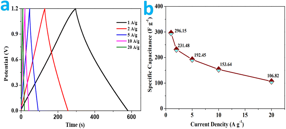 | ||
| Fig. 9 (a) Galvanostatic charge/discharge curves of the RMAC//RMAC symmetrical supercapacitor at different current densities; (b) specific capacitances of the as-assembled RMAC symmetrical supercapacitor based on the total mass of the active materials of the two electrodes at different current densities. | ||
The excellent areal capacitance and high rate capability confirm superior energy storage performance of the symmetrical RMACs. To validate the applicability of RMAC-4 as a power source (Fig. 10a), the energy and power densities based on the total mass of active materials in the two electrodes are calculated from the GCD profiles. Impressively, RMAC//RMAC achieves an energy density of around ∼59.23 W h kg−1 at a power density of 1.2 kW kg−1. Moreover, an energy density value of ∼21.364 W h kg−1 could also be attained at 24 kW kg−1. Such remarkable energy and power densities are superior to commercial supercapacitors (3–5 W h kg−1) and other carbonaceous symmetric supercapacitors derived from biomass75–77 and comparable to the performance of some asymmetric suppercapacitors.55,78 The superior functions could be ascribed to the special structure of the carbon materials such as an ultrahigh specific surface area and broadened pore distribution as well as heteroatom doping, which contribute to rapid ion diffusion, ample charge storage, and additional pseudo-capacitance.79
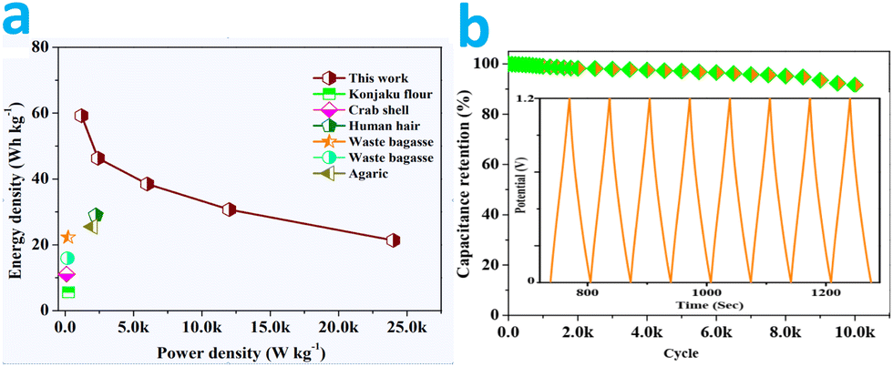 | ||
| Fig. 10 (a) Ragone plots of the RMAC symmetrical supercapacitor and other previously reported carbon-based symmetrical supercapacitors and (b) cycle performance of the RMAC symmetrical supercapacitor at a current density of 10 A g−1 (inset photograph of the GCD electrode curves for recycling). | ||
In our case, the GCD cycling profiles are obtained to investigate the cycling stability of the supercapacitor at a current load of 10 A g−1 (Fig. 10b). After 10000 cycles, there is a loss of only 8.4% compared with the starting specific capacitance value, revealing the good cycling stability for its potential practical application. A small attenuation for the supercapacitors can be ascribed to the increased electrical resistance in the devices. The outstanding cycling stability may be attributed to the firm bonding of the functional groups to the carbon surface in the process of the cycling, and the reversible Faraday reactions originating from the surface functionalgroups.80
In addition, the supercapacitor based on RMAC can be employed in various electronics. According to Fig. S7, (ESI†) the operating voltage range could be further broadened by the linking two or three devices. A tandem device could lighten a red light-emitting-diode lamp (LED, the lowest working potential is 2.0 V). These LEDs can be continuously powered on. These results demonstrate that the symmetric RMACs satisfy the requirements of practical energy storage devices. Moreover, the approach is considerably prospective to switch on the window for legitimately devising ideal hierarchical porous carbon materials as the electrode material, and further contributing to the synthesis guidance of high-energy storage materials for supercapacitors.
Conclusions
In summary, the advantages of eco-friendliness, simplicity, and scalability of the KOH activating method have been exploited to synthesize nanoscale RMAC samples. The plenty of hierarchical pores and high specific surface area of the as-synthesized materials contribute to superior electrochemical performances. RMAC-4 presents a capacitance of ∼796 F g−1 at 1 A g−1 and the cycling performances with 93.6% retention after 10000 cycles. Moreover, the RMAC//RMAC devices demonstrate a good specific capacitance of ∼296 F g−1 at 1 A g−1, and a superior energy density of ∼59 W h kg−1 at 1.2 kW kg−1 as well as high cycling stability with depletion of 8.4% capacitance after 10000 cycles. The assembled devices exhibit considerable specific capacitance, operational stability, and synergetic energy–power output characteristics in practical applications, which will improve the industrialization of biomass materials for green and sustainable energy storage devices.
Conflicts of interest
There are no conflicts to declare.Acknowledgements
We sincerely acknowledge the financial support from the Faculty of Materials and Energy and the Institute for Clean Energy & Advanced Materials, the Southwest University and Chongqing Key Laboratory for Advanced Materials and Technologies of Clean Electrical Power Sources and the Natural Science Foundation of Chongqing, China (cstc2020jcyj-msxmX0019).References
- S. G. Krishnan, A. Arulraj, P. Jagadish, M. Khalid, M. Nasrollahzadeh, R. Fen, C. C. Yang and G. Hegde, Crit. Rev. Solid. State, 2022 DOI:10.1080/10408436.2022.2027225.
- F. El-Kady, V. Strong, S. Dubin and R. Kaner, Science, 2012, 335, 1326 CrossRef PubMed.
- J. Acharya, G. P. Ojha, B. Pant and M. Park, J. Mater. Chem. A, 2021, 9, 23977 RSC.
- J. J. Zhu, Y. Sun, J. Gao, Z. B. Qin, Y. N. Zhou, R. Tian and Y. Gao, Chem. Commun., 2022, 58, 5861 RSC.
- S. S. Bengtsen, L. Hamelin, L. Bregnbæk, L. Zou and M. Münster, Energy Environ. Sci., 2022, 15, 1950 RSC.
- D. K. Lee, D. Lee, M. A. Lumley and K.-S. Choi, Chem. Soc. Rev., 2019, 48, 2126 RSC.
- S. Liu, D. Ni, H. F. Li, K. N. Hui, C. Y. Ouyang and S. C. Jun, J. Mater. Chem. A, 2018, 6, 10674 RSC.
- S. W. Zhang, B. S. Yin, X. X. Liu, D. M. Gu, H. Gong and Z. B. Wang, Nano Energy, 2019, 59, 41 CrossRef CAS.
- W. Song, X. Teng, Y. Liu, J. Wang, Y. Niu, X. He, C. Zhang and Z. Chen, Nanoscale, 2019, 11, 6401 RSC.
- C. Miao, C. Zhou, H. E. Wang, K. Zhu, K. Ye, Q. Wang, J. Yan, D. Cao, N. Li and G. Wang, J. Power Sources, 2021, 490, 229532 CrossRef CAS.
- J. Acharya, G. P. Ojha, B. S. Kim, B. Pant and M. Park, ACS Appl. Mater. Interfaces, 2021, 13, 17487 CrossRef CAS.
- X. T. Ren, N. Meng, L. Ventura, S. Goutianos, E. Barbieri, H. Zhang, H. X. Yan, M. J. Reece and E. Bilotti, J. Mater. Chem. A, 2022, 10, 10171 RSC.
- M. Kumar and T. C. Nagaiah, J. Mater. Chem. A, 2022, 10, 10979 RSC.
- Z. H. Huang, Y. Song, D. Y. Feng, Z. Sun, X. Sun and X. X. Liu, ACS Nano, 2018, 12, 3557 CrossRef CAS PubMed.
- S. Q. Zhu, J. C. Shu and M. S. Cao, Nanoscale, 2022, 14, 7322 RSC.
- R. T. Zhou, Y. Li and K. H. Lam, J. Mater. Chem. A, 2021, 9, 21302 RSC.
- J. H. Lee, S. P. Park, K. Park and H. J. Kim, Adv. Funct. Mater., 2020, 30, 1907437 CrossRef CAS.
- C. C. Zhang, Q. Li, T. D. Wang, Y. D. Miao, J. Q. Qi, Y. W. Sui, Q. K. Meng, F. X. Wei, L. Zhu, W. Zhang and P. Cao, Nanoscale, 2022, 14, 6339 RSC.
- X. Zhao, P. Pachfule and A. Thomas, Chem. Soc. Rev., 2021, 50, 6871 RSC.
- P. B. Geng, S. S. Zheng, H. Tang, R. M. Zhu, L. Zhang, S. Cao, H. G. Xue and H. Pang, Adv. Energy Mater., 2018, 8, 1703259 CrossRef.
- D. W. Wang, J. W. Nai, H. Li, L. Xu and Y. T. Wang, Carbon, 2019, 141, 40 CrossRef CAS.
- D. W. Wang, J. W. Nai, L. Xu and T. Sun, ACS Sustainable Chem. Eng., 2019, 7, 18901 CrossRef CAS.
- P. C. Zhou, F. Xiao, R. X. Weng, Q. G. Huang, L. Wang, Q. H. He, W. S. Tang, P. L. Yang, R. Su, P. He, B. Jia and L. Bian, J. Mater. Chem. A, 2022, 10, 10514 RSC.
- Z. Li, J. J. Wei, J. Ren, X. M. Wu, L. Wang, D. Y. Pan and M. H. Wu, Carbon, 2019, 154, 410 CrossRef CAS.
- Z. Q. Li, Y. Yang, G. H. Ding, L. Z. Wei, G. Yao, H. L. Niu, F. C. Zheng and Q. W. Chen, J. Mater. Chem. A, 2022, 10, 10033 RSC.
- R. W. Shu, Z. L. Wan, J. B. Zhang, Y. Wu, Y. Liu, J. J. Shi and M. D. Zheng, ACS Appl. Mater. Interfaces, 2020, 12, 4689 CrossRef CAS PubMed.
- S. F. Chen, C. J. Zhu, W. P. Xian, X. Y. Liu, X. L. Liu, Q. H. Zhang, S. Q. Ma and Q. Sun, J. Am. Chem. Soc., 2021, 143(25), 9415 CrossRef CAS PubMed.
- D. Y. Gao, Y. F. Pan, J. H. Wei, D. D. Han, P. C. Xu, Y. Wei, L. C. Mao and X. H. Yin, J. Mater. Chem. A, 2022, 10, 11186 RSC.
- X. Liu, W. Q. Yuan and R. Y. Zhao, ACS Food Sci. Technol., 2021, 1(6), 1041 CrossRef CAS.
- S. Zhang, P. C. Dai, H. J. Liu, L. T. Yan, H. X. Song, D. D. Liu and X. B. Zhao, ACS Appl. Energy Mater., 2020, 3(12), 12627 CrossRef CAS.
- I. Mukherjee, V. Cilamkoti and R. K. Dutta, ACS Appl. Nano Mater., 2021, 4(8), 7686 CrossRef CAS.
- S. Zhi, X. Tang, Z. N. Zheng, F. X. Xu, Y. H. Ren and X. L. Wang, Russ. J. Plant Physiol., 2020, 67(4), 703 CrossRef CAS.
- Z. Y. Liu, Y. Yang, Y. N. Yuan, L. D. Wang, J. Sheng and W. D. Fei, J. Mater. Chem. A, 2022, 10, 10427 RSC.
- Z. Xu, F. Xie, J. Wang, H. Au, M. Tebyetekerwa, Z. Y. Guo, S. Y. Yang, Y. S. Hu and M. M. Titirici, Adv. Funct. Mater., 2019, 29, 1903895 CrossRef.
- H. Peng, B. Yao, X. Wei, T. Liu, T. Kou, P. Xiao, Y. Zhang and Y. Li, Adv. Energy Mater., 2019, 9, 1803665 CrossRef.
- Y. Q. Shan, Z. X. Xu, P. G. Duan, H. L. Fan, X. Hu and R. Luque, ACS Sustainable Chem. Eng., 2020, 8, 15809 CrossRef CAS.
- K. Jayaramulu, M. Horn, A. Schneemann, H. Saini, A. Bakandritsos, V. Ranc, M. Petr, V. Stavila, C. Narayana, B. Scheibe, Š. Kment, M. Otyepka, N. Motta, D. Dubal, R. Zbořil and R. A. Fischer, Adv. Mater., 2021, 33, 2004560 CrossRef CAS PubMed.
- L. M. Chen, H. Y. Yu, Z. H. Li, X. Chen and W. L. Zhou, Nanoscale, 2021, 13, 17837 RSC.
- K. Zhang, H. Y. Zeng, M. X. Wang, H. B. Li, W. Yan, H. B. Wang and Z. H. Tang, J. Mater. Chem. A, 2022, 10, 11213 RSC.
- C. Dang, Z. Huang, Y. Chen, S. Zhou, X. Feng, G. Chen, F. Dai and H. Qi, ACS Appl. Mater. Interfaces, 2020, 12, 21528 CrossRef CAS PubMed.
- C. X. Guo and C. M. Li, Energy Environ. Sci., 2011, 4, 4504 RSC.
- Z. Bi, Q. Kong, Y. Cao, G. Sun, F. Su, X. Wei, X. Li, A. Ahmad, L. Xie and C. M. Chen, J. Mater. Chem. A, 2019, 7, 16028 RSC.
- Y. Dong, S. Zhang, X. Du, S. Hong, S. Zhao, Y. Chen, X. Chen and H. Song, Adv. Funct. Mater., 2019, 29, 1901127 CrossRef.
- T. X. Ma, Y. Z. Pan, J. Y. Chen, Z. M. Yan, B. X. Chen, L. Zhao, L. W. Hu, L. Y. Wen and M. L. Hu, J. Mater. Chem. A, 2022, 10, 9932 RSC.
- J. L. W. Morgan, J. Strumillo and J. Zimmer, Nature, 2013, 493, 181 CrossRef CAS PubMed.
- S. Y. Wang, Z. W. Hu, Z. M. Pan and D. W. Wang, J. Alloys Compd., 2021, 876, 160203 CrossRef CAS.
- T. Shang, Y. Xu, P. Li, J. Han, Z. Wu, Y. Tao and Q. H. Yang, Nano Energy, 2020, 70, 104531 CrossRef CAS.
- C. Li, Y. W. Ding, B. C. Hu, Z. Y. Wu, H. L. Gao, H. W. Liang, J. F. Chen and S. H. Yu, Adv. Mater., 2020, 32, 1904331 CrossRef CAS PubMed.
- C. Liu, H. Wang, X. Zhao, H. Liu, Y. Sun, L. Tao, M. Huang, J. Shi and Z. Shi, J. Power Sources, 2020, 457, 228056 CrossRef CAS.
- R. Guo, C. Lv, W. Xu, J. Sun, Y. Zhu, X. Yang, J. Li, J. Sun, L. Zhang and D. Yang, Adv. Energy Mater., 2020, 10, 1903652 CrossRef CAS.
- Z. X. Xu, X. Q. Deng, S. Zhang, Y. F. Shen, Y. Q. Shan, Z. M. Zhang, R. Luque, R. Luque, P. G. Duan and X. Hu, Green Chem., 2020, 22, 3885 RSC.
- Y. Yang, K. P. Wang, Q. Zang, Q. Q. Shi, Y. W. Wang, Z. Y. Xiao, Q. Zhang and L. Wang, J. Mater. Chem. A, 2022, 10, 11277 RSC.
- H. Luo, P. Xiong, J. Xie, Z. Yang, Y. Huang, J. Hu, Y. Wan and Y. Xu, Adv. Funct. Mater., 2018, 28, 1803075 CrossRef.
- S. Qiu, L. Xiao, M. L. Sushko, K. S. Han, Y. Shao, M. Yan, X. Liang, L. Mai, J. Feng, Y. Cao, X. Ai, H. Yang and J. Liu, Adv. Energy Mater., 2017, 7, 1700403 CrossRef.
- D. W. Wang, S. Y. Wang and Z. M. Lu, Int. J. Energy Res., 2021, 2, 2498 CrossRef.
- X. Yang, Q. Wang, K. Zhu, K. Ye, G. Wang, D. Cao and J. Yan, Adv. Funct. Mater., 2021, 31, 2101087 CrossRef CAS.
- X. Tang, H. Zhou, Z. Cai, D. Cheng, P. He, P. Xie, D. Zhang and T. Fan, ACS Nano, 2018, 12, 3502 CrossRef CAS PubMed.
- L. Zhang, C. Yang, N. Hu, Z. Yang, H. Wei, C. Chen, L. Wei, Z. J. Xu and Y. Zhang, Nano Energy, 2016, 26, 668 CrossRef CAS.
- X. Li, H. Li, X. Fan, X. Shi and J. Liang, Adv. Energy Mater., 2020, 10, 1903794 CrossRef CAS.
- X. Wang, H. Li, H. Li, S. Lin, W. Ding, X. Zhu, Z. Sheng, H. Wang, X. Zhu and Y. Sun, Adv. Funct. Mater., 2020, 30, 1910302 Search PubMed.
- J. Yan, Q. Wang, T. Wei and Z. Fan, Adv. Energy Mater., 2014, 4, 1300816 CrossRef.
- M. Lv, X. Zhang, F. Wang, T. Yu, H. Lv, Y. Zhai, Y. Shen and G. Lv, Nanotechnology, 2020, 31, 225603 CrossRef CAS PubMed.
- X. Y. Zhao, Q. Bi, C. Yang, K. Tao and L. Han, Dalton Trans., 2021, 50, 15260 RSC.
- F. Wang, X. Wu, X. Yuan, Z. Liu, Y. Zhang, L. Fu, Y. Zhu, Q. Zhou, Y. Wu and W. Huang, Chem. Soc. Rev., 2017, 46, 6816 RSC.
- W. Raza, F. Ali, N. Raza, Y. Luo, K.-H. Kim, J. Yang, S. Kumar, A. Mehmood and E. E. Kwon, Nano Energy, 2018, 52, 441 CrossRef CAS.
- B. Dunn, H. Kamath and J. M. Tarascon, Science, 2011, 334, 928 CrossRef CAS PubMed.
- Y. Wang and Y. Xia, Adv. Mater., 2013, 25, 5336 CrossRef CAS PubMed.
- A. Bavykina, N. Kolobov, I. S. Khan, J. A. Bau, A. Ramirez and J. Gascon, Chem. Rev., 2020, 120, 8468 CrossRef CAS PubMed.
- P. Zhang, B. Y. Guan, L. Yu and X. W. Lou, Angew. Chem., Int. Ed., 2017, 56, 7141 CrossRef CAS PubMed.
- Y. Zhang, N. Cao, S. Szunerits, A. Addad, P. Roussel and R. Boukherroub, Chem. Eng. J., 2019, 374, 347 CrossRef.
- M. K. Peng, W. Z. Yang, L. B. Li, K. Y. Zhang, L. Wang, T. Hu, K. Yuan and Y. W. Chen, Chem. Commun., 2021, 57, 10731 RSC.
- X. Gao, X. Du, T. S. Mathis, M. Zhang, X. Wang, J. Shui, Y. Gogotsi and M. Xu, Nat. Commun., 2020, 11, 6160 CrossRef CAS PubMed.
- X. F. Chen, Y. Z. Zhu, M. Zhang, J. Y. Sui, W. C. Peng, Y. Li, G. L. Zhang, F. B. Zhang and X. B. Fan, ACS Nano, 2019, 13, 9449 CrossRef CAS PubMed.
- Y. Cao, X. Tian, J. Gu, B. Liu, B. Zhang, S. Song, F. Fan and Y. Chen, Angew. Chem., Int. Ed., 2018, 57, 4543 CrossRef CAS PubMed.
- Y. Zhang, S. Liu, X. Zheng, X. Wang, Y. Xu, H. Tang, F. Kang, Q. H. Yang and J. Luo, Adv. Funct. Mater., 2017, 27, 1604687 CrossRef.
- M. Zohair, K. Moyer, J. E. Rathert, C. Meng, J. Waugh and C. L. Pint, ACS Nano, 2020, 14, 2308 CrossRef CAS PubMed.
- B. Zhu, B. Liu, C. Qu, H. Zhang, W. Guo, Z. Liang, F. Chen and R. Zou, J. Mater. Chem. A, 2018, 6, 1523 RSC.
- D. W. Wang, Z. M. Pan, G. X. Chen and Z. M. Lu, Electrochim. Acta, 2021, 379, 138170 CrossRef CAS.
- Y. Shabangoli, M. S. Rahmanifar, M. F. El-Kady, A. Noori, M. F. Mousavi and R. B. Kaner, Adv. Energy Mater., 2018, 8, 1802869 CrossRef.
- W. Yan, J. Su, Z. M. Yang, S. Lv, Z. Jin and J. L. Zuo, Small, 2021, 17, 200520 Search PubMed.
Footnotes |
| † Electronic supplementary information (ESI) available. See DOI: https://doi.org/10.1039/d2ma00426g |
| ‡ These authors contributed equally to this work. |
| This journal is © The Royal Society of Chemistry 2022 |