 Open Access Article
Cross-linked copolymer-derived nitrogen-doped hierarchical porous carbon with high-performance lithium storage capability†
Rui
Luo‡
a,
Zhengwei
Wan‡
b,
Peng
Mei
 *ac,
Zhengjiao
Xie
a,
Dean
Shi
c and
Yingkui
Yang
*ab
aKey Laboratory of Catalysis and Energy Materials Chemistry of Ministry of Education & Hubei Key Laboratory of Catalysis and Materials Science, South-Central Minzu University, Wuhan 430074, China. E-mail: meipeng@scuec.edu.cn
bHubei Engineering Technology Research Centre of Energy Polymer Materials, School of Chemistry and Materials Science, South-Central Minzu University, Wuhan 430074, China. E-mail: ykyang@mail.scuec.edu.cn
cMinistry-of-Education Key Laboratory for Green Preparation and Application of Functional Materials, Hubei University, Wuhan 430074, China
First published on 15th July 2022
Abstract
Here we describe a facile, low-cost, and scalable synthesis of nitrogen-doped hierarchical porous carbon (N-HPC) through a contemporaneous carbonization–activation process of a cross-linked polymer obtained by the one-step copolymerization of divinylbenzene (DVB) and 1-vinylimidazole (VI) monomers. The as-prepared N-HPC features a high surface area of up to 1685 m2 g−1 with the coexistence of abundant micro-, meso-, and macropores. When applied in lithium-ion batteries (LIBs), the N-HPC anode exhibits superior initial reversal capacity (1045.9 mA h g−1 at 0.1 A g−1), cyclic stability (retention of 73.6% at 2 A g−1 after 1000 cycles) and rate capability (450.5 mA h g−1 at 2 A g−1) on account of its architectural and compositional superiority compared with either the HPC material carbonized from the self-polymerization product of DVB or commercial graphite. We believe that this work can provide new impetus to the large-scale implementation of high-performance and affordable LIBs that are pivotal in the sustainable development of our society.
Introduction
The world is currently seeing the major impact of energy shortage and environmental degradation on a very large scale due to the exhaustion of non-renewable fossil fuels. To cope with such dual challenges, scientists are driven to exploit clean, sustainable, and affordable energy sources. Hence, lithium-ion batteries (LIBs) have been devised and stand out by virtue of their high energy density, long cycle life, wide operating voltage/temperature range, and environmental benignity. LIBs have seen tremendous success in consumer electronic markets, yet emerging applications such as electrified transportation and grids put forward higher requirements on their performance, especially the energy density.1,2 Electrode materials (cathode and anode) as an essential part of the battery system are critical to the performance parameters of the device.3 Essentially, the energy density of LIBs is governed by the lithium storage capacities and working voltages of the respective electrodes.4 Dedicated efforts have been devoted to the development of various electrode materials with large capacities and moderately low voltages to attain this energy goal.As a predominantly used commercial anode material for LIBs, graphite has a relatively low theoretical capacity of only 372 mA h g−1, and is gradually approaching its limit. Still, carbon materials have long appealed to researchers as promising anode candidates because of their easy approachability, good electrical conductivity, stable physicochemical properties, low average voltage, and nontoxicity.5 Among them, porous carbon materials such as activated carbon, carbon aerogels,6 and carbon nanotubes7 have attracted extensive research interest owing to their highly exposed surface area, large pore volume, and devisable pore structure.8–10 In general, macropores (> 50 nm) and mesopores (2–50 nm) are advantageous to the infiltration of electrolytes into the electrode. Mesopores and micropores (< 2 nm) are conducive to large electrochemical accessible surface areas to increase the active material utilization. Besides, micropores might serve as lithium-ion reservoirs that further enhance the storage capacity.11,12 Nevertheless, the energy storage capability of conventional porous carbon materials with only macro-, meso- or micropores is not very satisfactory due to the lack of expedited diffusion pathways and sufficiently exposed surfaces.
In this context, hierarchical porous carbons (HPCs) integrated with micro-, meso-, and macropores are expected to exhibit comprehensively improved electrochemical properties as LIBs anodes, benefiting from the synergetic contributions of multimodal nanopores and their pore interconnections.13,14 Thus, the synthesis and application of hierarchical porous carbon materials have become a hot research topic.15 While templating methods have been frequently used to prepare porous carbon materials, the removal of many templates is tedious, time-consuming and sometimes involves hazardous reagents.16 Therefore, developing a simple, efficient and cost-effective synthetic strategy for HPCs is intriguing and challenging. In recent years, a variety of polymers have been documented as excellent carbon precursors by virtue of their easy synthesis, low cost, flexible morphology control, and decent carbon yield.5,17 Through appropriate thermal treatment of such polymers, abundant nanopores at different dimensions can be obtained in the resultant carbon materials. Moreover, the inherent heteroatoms (e.g., N, S, P) in some polymers can act as in situ dopants to decorate the carbon framework, which can not only modify the electronic properties of the material but also enhance the electrode/electrolyte affinity, thereby further improving the storage capacity of lithium ions.18–20
In the present study, we have fabricated a nitrogen-doped hierarchical porous carbon (N-HPC) material via the direct carbonization of a KOH-impregnated polymer obtained from divinylbenzene (DVB) and 1-vinylimidazole (VI) monomers, featuring a high specific surface area of 1685 m2 g−1 with wide pore size distributions. When examined as a LIBs anode, the as-prepared N-HPC exhibits an appreciably enhanced initial reversible capacity, rate performance and durability with respect to the HPC material prepared by the pyrolysis of the self-polymerization product of DVB or commercial graphite.
Results and discussion
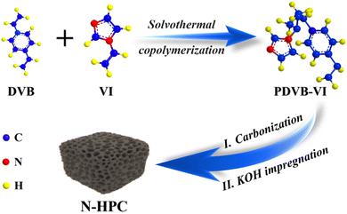
Scheme 1 illustrates the synthetic protocol of the nitrogen-doped hierarchical porous carbon (N-HPC) material derived from a divinylbenzene (DVB)-based porous organic polymer through a simultaneous carbonization–activation process. As can be seen from the Fourier transform infrared (FT-IR) spectra in Fig. S1 (ESI†), two new adsorption bands at around 1226 cm−1 and 1647 cm−1 corresponding to the N–H and C![[double bond, length as m-dash]](https://www.rsc.org/images/entities/char_e001.gif) N stretching vibrations can be found in the copolymer (PDVB-VI) in relation to its counterpart (PDVB).21 The FT-IR results clearly indicate that the imidazole group has been successfully grafted onto the polymer skeleton, which could work as a nitrogen dopant post heat treatment. The TG curves of the two polymers are plotted in Fig. S2 (ESI†), displaying similar thermal decomposition behavior. The relatively high decomposition temperatures evidence the good chemical stability of the obtained DVB-based polymers, which can give a clue to the high degree of crosslinking of the network.21 In addition, a higher residual weight percentage is obtained for PDVB-VI (>25%) than for PDVB (∼17%), suggesting a larger carbon yield for the copolymer precursor.
N stretching vibrations can be found in the copolymer (PDVB-VI) in relation to its counterpart (PDVB).21 The FT-IR results clearly indicate that the imidazole group has been successfully grafted onto the polymer skeleton, which could work as a nitrogen dopant post heat treatment. The TG curves of the two polymers are plotted in Fig. S2 (ESI†), displaying similar thermal decomposition behavior. The relatively high decomposition temperatures evidence the good chemical stability of the obtained DVB-based polymers, which can give a clue to the high degree of crosslinking of the network.21 In addition, a higher residual weight percentage is obtained for PDVB-VI (>25%) than for PDVB (∼17%), suggesting a larger carbon yield for the copolymer precursor.
The morphology of the as-prepared N-HPC was surveyed by scanning electron microscopy (SEM). The representative SEM images in Fig. 1(a) and (b) distinctly verify the existence of abundant pores with a wide pore size distribution (PSD). The inset in Fig. 1(a) shows that the pore diameter of N-HPC ranges from 20 to 140 nm and is centered around 60–80 nm. A closer inspection of the microstructure of N-HPC was conducted by scanning transmission electron microscopy (STEM). The typical TEM (Fig. 1(c)), STEM (Fig. 1(d) and Fig. S3a, ESI†) and HR-TEM (Fig. S3b, ESI†) images further substantiate the well-resolved hierarchical porosity of N-HPC, spanning from micropores and mesopores to macropores, which might provide increased storage capacity and improved transportation property for lithium ions.22–24 The corresponding elemental mapping (Fig. 1(e) and (f)) clearly reveals the uniform distribution of C and N elements throughout the selected area of the N-HPC sample, which ascertains the incorporation of nitrogen atoms into the carbon skeleton.
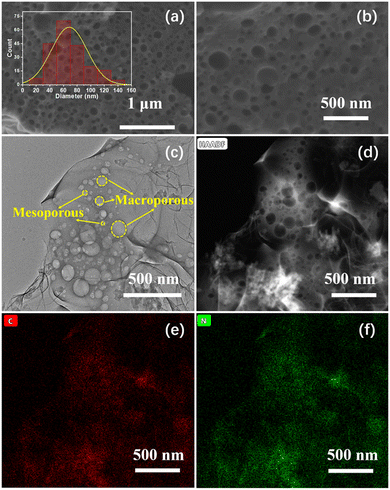 | ||
| Fig. 1 (a) and (b) SEM, (c) TEM, and (d) STEM images of N-HPC, with the corresponding elemental mapping (e), (f). | ||
The porous architecture of the as-obtained N-HPC was further examined by nitrogen adsorption–desorption analysis. In light of the IUPAC classification, N-HPC displays a combined type-I(a)/IV(a) isotherm (Fig. 2(a)).25 The significant N2 adsorption in the low-pressure zone (P/P0 < 0.1) indicates the dominance of micropores, while a rise at relatively high pressures (P/P0 > 0.9) implies the existence of macropores.26,27 Notably, in the medium–high pressure region, a capillary condensation is accompanied by hysteresis, which is a characteristic of mesopores.28 While the control sample HPC follows a similar physisorption pattern, N-HPC exhibits a remarkably increased micropore filling at very low P/P0. Thus, the micropore volume of N-HPC is assumed to be much larger than that of HPC, which generally leads to a higher specific surface area. Fig. 2(b) depicts the PSDs obtained from the adsorption branches in the medium-to-high pressures using the Barrett–Joyner–Halenda (BJH) model. A broadened peak centered at around 60–70 nm is found for N-HPC in the meso- to macropore range, which is in accordance with the SEM observation. The PSDs acquired from the isotherm at low pressures using the Horvath–Kawazoe (HK) method is presented in the inset of Fig. 2(b), showing sharp peaks at 0.70 nm and 0.68 nm for N-HPC and HPC, respectively. The above N2 physisorption analysis corroborates the hierarchy of porosity covering micro-, meso- and macropores in the obtained samples, which should be caused by the decomposition of organic segments and KOH-etching.
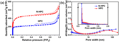 | ||
| Fig. 2 (a) Nitrogen adsorption–desorption isotherms and the (b) corresponding pore size distributions of N-HPC and HPC. | ||
The detailed porosity parameters are summarized in Table S1 (ESI†). As expected from the physisorption isotherms, N-HPC doubles the micropore volume in comparison to that of HPC, presumably due to the introduction of VI into the polymerization, which brings a higher degree of cross-linking and hence generates more micropores in the carbonization process. Consequently, the specific surface area of N-HPC acquired by from the multipoint Brunauer–Emmett–Teller (BET) method is up to 1685 m2 g−1, twice that of HPC (∼815 m2 g−1). It has been well documented that the lithium storage capability of an electrode is closely related to the high specific surface area of the active material and the pore structure of different structural levels.14,17,29,30 Due to the synergetic benefit of the well-developed hierarchical porous texture and N-doping, the cross-linked copolymer-derived N-HPC is anticipated to hold great advantages as a LIBs anode material over its counterpart.
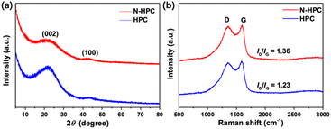
As shown in Fig. 3(a), the X-ray diffraction (XRD) patterns of both N-HPC and HPC display two typical peaks near 23° and 43°, representing the (002) and (100) crystal planes of graphitic carbon, respectively. The relatively low intensity and broad shape of these two diffraction peaks imply that the carbon materials obtained herein are principally amorphous/disordered in nature. According to previous studies, the empirical parameter (R), defined as the ratio of the height of the (002) Bragg peak to the background, shows a close correlation with the nonparallel single layer content in carbon materials. To be specific, carbon samples with smaller R values (< 2) generally contain larger amounts of randomly oriented single layers, and in turn deliver higher lithium storage capacities.31–33 A schematic for the calculation of parameter R is presented in Fig. S4 (ESI†). A lower R value is obtained for N-HPC (1.48) than for HPC (1.98), manifesting an increased nonparallel single layer content in the former sample, which could further enhance its reversible capacity when used as a LIBs anode. The difference in the R values is most possibly due to the introduction of nitrogen atoms into the skeleton of N-HPC, which interferes with the progression of graphitization and generates more defects.
The Raman spectra (Fig. 3(b)) of N-HPC and HPC unveil two pronounced peaks at 1345 cm−1 and 1580 cm−1, which are assignable to the characteristic D (disorder/defects) and G (graphitic) bands of carbon materials, respectively.34 The intensity ratio of the D and G bands (ID/IG) is normally employed to estimate the degree of structural ordering for carbons, which turns out to be 1.36 and 1.23 for N-HPC and HPC, respectively, denoting their amorphous/disordered feature. The higher ID/IG value of N-HPC reflects an increase in structural disordering/defects in the carbon skeleton of N-HPC,35–37 which is consistent with the results of the XRD measurements.
X-ray photoelectron spectroscopy (XPS) was performed to further investigate the surface chemistry of N-HPC. Evidently, the XPS survey spectrum (Fig. 4(a)) validates the presence of carbon and nitrogen in N-HPC, which agrees with the elemental analysis from STEM. As shown in Fig. 4(b), the high-resolution C 1s XPS spectrum can be deconvoluted into four peaks at 284.8, 285.8, 287.7 and 290.1 eV, corresponding to C–C/C![[double bond, length as m-dash]](https://www.rsc.org/images/entities/char_e001.gif) C, C–N/C–O, COOH and π–π*.38 Amongst them, the chemical bonding between carbon and carbon has predominance in the carbon framework. The high-resolution O 1s spectrum (Fig. 4(c)) of N-HPC is divided into three peaks at 531.9, 533.6, and 534.4 eV, disclosing the existence of different oxygen functionalities (C
C, C–N/C–O, COOH and π–π*.38 Amongst them, the chemical bonding between carbon and carbon has predominance in the carbon framework. The high-resolution O 1s spectrum (Fig. 4(c)) of N-HPC is divided into three peaks at 531.9, 533.6, and 534.4 eV, disclosing the existence of different oxygen functionalities (C![[double bond, length as m-dash]](https://www.rsc.org/images/entities/char_e001.gif) O, C–O, and COOH, respectively).39Fig. 4(d) depicts the peak fitting results of the high-resolution N 1s spectrum, identifying four distinct components of nitrogen, including pyridinic N at 399.1 eV, pyrrolic N at 399.9 eV, graphitic N at 400.8 eV, and oxidized pyridinic-N at 402.3 eV.40–42 Previous experimental and theoretical investigations indicate that the pyridinic/pyrrolic N decorations on carbons can not only modify their electronic property but also serve as electrochemically active sites for extra lithium accommodation.35,40,43,44
O, C–O, and COOH, respectively).39Fig. 4(d) depicts the peak fitting results of the high-resolution N 1s spectrum, identifying four distinct components of nitrogen, including pyridinic N at 399.1 eV, pyrrolic N at 399.9 eV, graphitic N at 400.8 eV, and oxidized pyridinic-N at 402.3 eV.40–42 Previous experimental and theoretical investigations indicate that the pyridinic/pyrrolic N decorations on carbons can not only modify their electronic property but also serve as electrochemically active sites for extra lithium accommodation.35,40,43,44
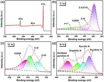 | ||
| Fig. 4 XPS spectra of N-HPC: (a) survey spectrum, (b) C 1s spectrum, (c) O 1s spectrum, (d) N 1s spectrum. | ||
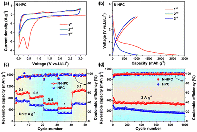
The electrochemical properties of N-HCP as a LIBs anode were evaluated by the standard half-cell configuration in a voltage window of 0.01–3.0 V vs. Li/Li+. Fig. 5(a) shows the first three cyclic voltammograms (CVs) of the N-HCP anode at a scan rate of 0.5 mV s−1. During the initial cathodic scan, a pronounced reduction peak at 0.42 V is clearly detected, which is generally acknowledged to be a consequence of electrolyte decomposition and of solid electrolyte interface (SEI) formation.35 It is worth noting that this peak has disappeared and the CV curves coincide well with each other from the second cycle onwards, signifying the good stability and reversibility of N-HCP. In the anodic scan, two weak oxidation peaks at around 0.2 V and 1.2 V should be credited to the lithium extraction from carbon layers and pores/defects, respectively.45,46 Besides, another broad oxidation peak can be observed at about 2.4 V, which is presumably associated with the interactions between lithium and the surface N atoms of carbon.40,47 In contrast, the N-related oxidation peak is absent in the CV curves of the undoped carbon sample HCP (Fig. S5a, ESI†). The galvanostatic charge–discharge profiles of N-HPC (Fig. 5(b)) for the initial three cycles were collected at 0.1 A g−1. In the first cycle, the N-HPC anode shows a reasonably high reversible capacity of 1045.9 mA h g−1 with a relatively low initial coulombic efficiency of 42.4%. The large irreversible capacity is mainly caused by the side reactions and SEI formation, which is common in nanomaterials, especially those with porous structures. Satisfyingly, the coulombic efficiency promptly increases to 89.2% and 90.9% for the subsequent two cycles. As expected, the HPC electrode shows a smaller initial reversible capacity (804.9 mA h g−1) than N-HPC (Fig. S5b, ESI†) on account of its less exposed active surface and the lack of heteroatom doping.
Fig. 5(c) illustrates the rate performance comparison of N-HPC and HPC. By increasing the current density stepwise, the reversible capacity of the N-HPC anode decreases slowly and steadily from 967.7 mA h g−1 at 0.1 A g−1 to 824.9, 606.6, and 451.6 mA h g−1 at 0.2, 0.5, and 1 A g−1, respectively, which readily outperforms the HPC anode at each rate. As the current density goes back to 0.1 A g−1, the reversible capacity of N-HPC can easily restore more than 100% of its initial value (1047.6 mA h g−1), while HPC struggles to retain just 85.8% of its original capacity (604.2 mA h g−1). This superior rate capability of N-HPC compared with that of HPC should be attributed to its high surface area, N-doping that provides more active sites, and optimized hierarchical porosity that affords expedited pathways for lithium diffusion and electron transfer. Fig. 5(d) presents the cycling stability of N-HPC and HPC at an even higher rate, which is of great importance to the actual demand of fast charging and long lifespan. The N-HPC anode delivers an appreciable reversible capacity of 450.5 mA h g−1 at 2 A g−1, which is close to the value at 1 A g−1. Although the reversible capacity of N-HPC undergoes gradual fading in the first few cycles, it quickly reaches a relatively stable level. After prolonged 1000 repeated charge–discharge cycles, N-HPC still delivers an appreciable capacity of 331.6 mA h g−1, corresponding to a decent retention rate of 73.6%, while the reversible capacity of HPC at the 1000th cycle is only 157.2 mA h g−1.
To shed some light on the considerably improved electrochemical performance of N-HPC, detailed kinetic analysis was performed with CV measurements at various scan rates along with electrochemical impedance spectroscopy (EIS). The CV curves display similar shapes with gradual peak broadening as the scan rate increases from 0.2 to 1 mV s−1 (Fig. S6a, ESI†). In general, the total energy stored in an electrode material is contributed by a diffusion-controlled faradaic process and/or a surface-controlled non-faradaic process, which can be qualitatively determined according to:
| i = avb |
The Nyquist plots (Fig. S7a, ESI†) of N-HPC and HPC both consist of a compressed semicircle in the high-to-medium frequency region, which describes the charge transfer resistance (Rct), and a low frequency tail related to the solid-state diffusion of ions. Judging by the diameter of the semicircle in the high-to-medium frequencies, the Rct value of N-HPC is estimated to be much lower than that of HPC, which may be ascribed to the N-doping that tailors the electronic properties. The impedance spectra can be further elucidated based on the equivalent circuit shown in the insert. As plotted in Fig. S7b (ESI†), the fitted Warburg factor (σ) value of N-HPC is smaller than that of HPC, indicating the faster lithium diffusion in the former electrode matrix.11,18 This could be explained by the architectural and compositional merits of N-HPC inherited from the cross-linked copolymer PDVB-VI: the high surface area provides large electrode/electrolyte interfaces, which can better absorb lithium and facilitate fast charge transfer reactions; the interconnected porous network can offer shortened pathways for rapid ion/electron transportation, and the plentiful nanopores in different sizes can help with lithium uptake; the pyridinic/pyrrolic nitrogen atoms doped in N-HCP can improve the electrochemical responsiveness and electronic conductivity, further contributing to its exceptional properties.
Experimental section
Materials
All reagents were of analytical grade and used without further purification. Divinylbenzene (DVB) and 1-vinylimidazole (VI) were obtained from Macklin (Shanghai, China). Azobisisobutyronitrile (AIBN), potassium hydroxide (KOH) and ethyl acetate were supplied by Sinopharm Chemical Reagent Co., Ltd.Synthesis of the precursors (PDVB-VI, PDVB)
In a typical synthesis, 4 mL DVB and 1 mL VI were first blended in 25 mL ethyl acetate under mild magnetic stirring for 30 min at room temperature. Next, 0.065 g AIBN was added to the above mixture with another 3 h of vigorous stirring. The solution was then stored in an autoclave at 120 °C for 24 h. The white gel product was ground up for natural air-drying, and was then washed with deionized water several times, followed by vacuum drying at 80 °C for 24 h to obtain a white powder copolymer (PDVB-VI). For comparison, the self-polymerization product of DVB, i.e., polydivinylbenzene (PDVB), was prepared through the same procedure without the addition of the N-containing monomer VI.Synthesis of the final product (N-HCP, HCP)
Initially, the precursor (PDVB-VI or PDVB) and KOH were blended in a mass ratio of 1![[thin space (1/6-em)]](https://www.rsc.org/images/entities/char_2009.gif) :
:![[thin space (1/6-em)]](https://www.rsc.org/images/entities/char_2009.gif) 4 and dispersed in a mixed solvent of ethanol and deionized water (v
4 and dispersed in a mixed solvent of ethanol and deionized water (v![[thin space (1/6-em)]](https://www.rsc.org/images/entities/char_2009.gif) :
:![[thin space (1/6-em)]](https://www.rsc.org/images/entities/char_2009.gif) v = 1
v = 1![[thin space (1/6-em)]](https://www.rsc.org/images/entities/char_2009.gif) :
:![[thin space (1/6-em)]](https://www.rsc.org/images/entities/char_2009.gif) 1) under vigorous stirring, followed by vacuum drying at 110 °C overnight. The mixed powder was annealed at 700 °C for 2 h under an Ar flow. Subsequently, the pyrolysis product was washed repeatedly with 3 M HCl solution, deionized water and ethanol, sequentially. Finally, the product was dried at 80 °C under vacuum for 12 h, and designated as N-HPC. The control sample (HCP) was prepared with the exact same post treatment of the precursor PDVB.
1) under vigorous stirring, followed by vacuum drying at 110 °C overnight. The mixed powder was annealed at 700 °C for 2 h under an Ar flow. Subsequently, the pyrolysis product was washed repeatedly with 3 M HCl solution, deionized water and ethanol, sequentially. Finally, the product was dried at 80 °C under vacuum for 12 h, and designated as N-HPC. The control sample (HCP) was prepared with the exact same post treatment of the precursor PDVB.
General characterization
The surface morphologies of the materials were observed using a Hitachi SU 8010 field-emission scanning electron microscope (SEM). Transmission electron microscopy (TEM) images were captured by a Thermo Scientific Talos F200X STEM. Nitrogen sorption measurements were collected on a Micromeritics ASAP 2020 Plus physisorption analyzer at 77 K. The X-ray diffraction (XRD) patterns were acquired using a D8 Advance X-ray diffractometer with Cu Kα radiation (λ = 1.5418 Å). X-ray photoelectron spectroscopy (XPS) was performed on a PHI Multi Pak spectrometer with a Mg Kα X-ray source. The Raman spectra were recorded on a Thermo Scientific DXR spectrometer at 532 nm excitation. The Fourier transform infrared (FT-IR) spectra were collected on a Thermo Nicolet NEXUS 470 spectrometer. Thermogravimetric analysis (TGA) was accomplished with a NETZSCH TG 209 F3 Tarsus instrument, with a heating rate of 10 °C min−1.Electrochemical measurements
The electrochemical performance of the as-synthesized materials was studied using CR2032 coin-type half-cells assembled in a glove box filled with inert gas. Specifically, the working electrode was fabricated by coating a mixed slurry of 80 wt% active materials, 10 wt% carbon black, and 10 wt% polyvinylidene fluoride (PVDF) on copper foil. Lithium foil was employed as a counter electrode and lithium hexafluorophosphate (LiPF6) was used as the electrolyte. Cyclic voltammetry (CV) and electrochemical impedance spectroscopy (EIS) were conducted on a CHI660E electrochemical workstation (Chenhua, China). The charge–discharge property measurements were implemented on multiple Land battery testing systems.Conclusion
In summary, a hierarchically porous carbon material with N-doping, N-HPC, has been developed by a synchronous activation–carbonization tactic using a cross-linked N-containing copolymer as the precursor, demonstrating tremendous potential as an alternative LIBs anode. The N-HPC electrode delivers an appreciably high reversible capacity of 1045.9 mA h g−1 at 0.1 A g−1, and achieves a desirable reversible capacity of 450.5 mA h g−1 at a 20-fold increased rate. Even after 1000 repeated cycles at a large current density of 2 A g−1, N-HPC retains 73.6% of its initial capacity. The enhanced comprehensive lithium storage capability of N-HPC should be attributed to the synergetic benefit of its multimodal porosity and pyridinic/pyrrolic nitrogen decorations, which offer elevated lithium accommodation capacity and accelerated lithium/electron transportation. This work is expected to highlight new opportunities for the mass production of polymer-derived carbon for affordable high-performance LIBs.Conflicts of interest
There are no conflicts to declare.Acknowledgements
This work was supported by the National Natural Science Foundation of China (51902350, 52173091, and 51973235), Program for Leading Talents of National Ethnic Affairs Commission of China (MZR21001), Hubei Provincial Natural Science Foundation of China (2021CFA022), Wuhan Science and Technology Bureau (2020010601012198), and Fundamental Research Funds for the Central Universities (CZP19001).Notes and references
- M. Li, J. Lu, X. Ji, Y. Li, Y. Shao, Z. Chen, C. Zhong and K. Amine, Nat. Rev. Mater., 2020, 5, 276–294 CrossRef CAS.
- P. Mei, J. Kim, N. A. Kumar, M. Pramanik, N. Kobayashi, Y. Sugahara and Y. Yamauchi, Joule, 2018, 2, 2289–2306 CrossRef CAS.
- S.-K. Jung, I. Hwang, D. Chang, K.-Y. Park, S. J. Kim, W. M. Seong, D. Eum, J. Park, B. Kim, J. Kim, J. H. Heo and K. Kang, Chem. Rev., 2020, 120, 6684–6737 CrossRef CAS PubMed.
- M. V. Reddy, G. V. Subba Rao and B. V. R. Chowdari, Chem. Rev., 2013, 113, 5364–5457 CrossRef CAS PubMed.
- H. Wang, Y. Shao, S. Mei, Y. Lu, M. Zhang, J.-k Sun, K. Matyjaszewski, M. Antonietti and J. Yuan, Chem. Rev., 2020, 120, 9363–9419 CrossRef CAS PubMed.
- G. Zeng, N. Shi, M. Hess, X. Chen, W. Cheng, T. Fan and M. Niederberger, ACS Nano, 2015, 9, 4227–4235 CrossRef CAS PubMed.
- D. Ge, L. Yang, A. Honglawan, J. Li and S. Yang, Chem. Mater., 2014, 26, 1678–1685 CrossRef CAS.
- M. R. Benzigar, S. N. Talapaneni, S. Joseph, K. Ramadass, G. Singh, J. Scaranto, U. Ravon, K. Al-Bahily and A. Vinu, Chem. Soc. Rev., 2018, 47, 2680–2721 RSC.
- Y. He, X. Zhuang, C. Lei, L. Lei, Y. Hou, Y. Mai and X. Feng, Nano Today, 2019, 24, 103–119 CrossRef CAS.
- X. Zhou, B. Liu, Y. Chen, L. Guo and G. Wei, Mater. Adv., 2020, 1, 2163–2181 RSC.
- J. Ou, L. Yang, Z. Zhang and X. Xi, J. Power Sources, 2016, 333, 193–202 CrossRef CAS.
- L. Tong, L.-L. Zhang, Y.-C. Wang, L.-Y. Wan, Q.-Q. Yan, C. Hua, C.-J. Jiao, Z.-Y. Zhou, Y.-W. Ding, B. Liu and H.-W. Liang, ACS Appl. Mater. Interfaces, 2020, 12, 25211–25220 CrossRef CAS PubMed.
- Y. Li, Z.-Y. Fu and B.-L. Su, Adv. Funct. Mater., 2012, 22, 4634–4667 CrossRef CAS.
- S. Dutta, A. Bhaumik and K. C. W. Wu, Energy Environ. Sci., 2014, 7, 3574–3592 RSC.
- M.-H. Sun, S.-Z. Huang, L.-H. Chen, Y. Li, X.-Y. Yang, Z.-Y. Yuan and B.-L. Su, Chem. Soc. Rev., 2016, 45, 3479–3563 RSC.
- B. R. Thompson, T. S. Horozov, S. D. Stoyanov and V. N. Paunov, J. Mater. Chem. A, 2019, 7, 8030–8049 CAS.
- X.-Y. Yang, L.-H. Chen, Y. Li, J. C. Rooke, C. Sanchez and B.-L. Su, Chem. Soc. Rev., 2017, 46, 481–558 RSC.
- W. Yu, H. Wang, S. Liu, N. Mao, X. Liu, J. Shi, W. Liu, S. Chen and X. Wang, J. Mater. Chem. A, 2016, 4, 5973–5983 RSC.
- C. Ma, C. Deng, X. Liao, Y. He, Z. Ma and H. Xiong, ACS Appl. Mater. Interfaces, 2018, 10, 36969–36975 CrossRef CAS PubMed.
- J. Wang, Y. Xia, Y. Liu, W. Li and D. Zhao, Energy Storage Mater., 2019, 22, 147–153 CrossRef.
- K. Huang, F. Liu and S. Dai, J. Mater. Chem. A, 2016, 4, 13063–13070 RSC.
- W. J. Roth, B. Gil, W. Makowski, B. Marszalek and P. Eliášová, Chem. Soc. Rev., 2016, 45, 3400–3438 RSC.
- J. Hwang, C. Jo, K. Hur, J. Lim, S. Kim and J. Lee, J. Am. Chem. Soc., 2014, 136, 16066–16072 CrossRef CAS PubMed.
- L. Peng, Y. Liang, J. Huang, L. Xing, H. Hu, Y. Xiao, H. Dong, Y. Liu and M. Zheng, ACS Sustainable Chem. Eng., 2019, 7, 10393–10402 CrossRef CAS.
- M. Thommes, K. Kaneko, A. V. Neimark, J. P. Olivier, F. Rodriguez-Reinoso, J. Rouquerol and K. S. W. Sing, Pure Appl. Chem., 2015, 87, 1051–1069 CrossRef CAS.
- W. Hu, F. Xie, Y. Li, Z. Wu, K. Tian, M. Wang, L. Pan and L. Li, Langmuir, 2017, 33, 13364–13375 CrossRef CAS PubMed.
- L.-F. Chen, X.-D. Zhang, H.-W. Liang, M. Kong, Q.-F. Guan, P. Chen, Z.-Y. Wu and S.-H. Yu, ACS Nano, 2012, 6, 7092–7102 CrossRef CAS PubMed.
- W. Xia, J. Tang, J. Li, S. Zhang, K. C. W. Wu, J. He and Y. Yamauchi, Angew. Chem., Int. Ed., 2019, 58, 13354–13359 CrossRef CAS PubMed.
- Q. Bai, Q. Xiong, C. Li, Y. Shen and H. Uyama, ACS Sustainable Chem. Eng., 2017, 5, 9390–9401 CrossRef CAS.
- Y.-l. Zhong, X.-q. Yin, L.-t. Wang, M.-f. Yuan, Y. Yao and G. Hong, Mater. Today Energy, 2020, 18, 100543 CAS.
- Y. Liu, J. S. Xue, T. Zheng and J. R. Dahn, Carbon, 1996, 34, 193–200 CrossRef CAS.
- H. Wang, Q. Gao and J. Hu, J. Am. Chem. Soc., 2009, 131, 7016–7022 CrossRef CAS PubMed.
- K. R. Saravanan and N. Kalaiselvi, Carbon, 2015, 81, 43–53 CrossRef CAS.
- D. Puthusseri, V. Aravindan, S. Madhavi and S. Ogale, Energy Environ. Sci., 2014, 7, 728–735 RSC.
- F. Zheng, Y. Yang and Q. Chen, Nat. Commun., 2014, 5, 5261 CrossRef CAS PubMed.
- M. Han, Y. Mu and J. Yu, Mater. Adv., 2020, 1, 421–429 RSC.
- H. Wang, L. Gou, W. Jing, D. An, Y. Li, M. Wang, N. Li, S. Hu and Y.-B. He, Mater. Adv., 2020, 1, 206–214 RSC.
- K. Wang, Y. Xu, Y. Li, V. Dravid, J. Wu and Y. Huang, J. Mater. Chem. A, 2019, 7, 3327–3335 RSC.
- F. Liu, Z. Wang, H. Zhang, L. Jin, X. Chu, B. Gu, H. Huang and W. Yang, Carbon, 2019, 149, 105–116 CrossRef CAS.
- J. P. Pender, J. V. Guerrera, B. R. Wygant, J. A. Weeks, R. A. Ciufo, J. N. Burrow, M. F. Walk, M. Z. Rahman, A. Heller and C. B. Mullins, ACS Nano, 2019, 13, 9279–9291 CrossRef CAS PubMed.
- B. Jiang, G. Zhang, Q. Tang, F. Meng, D. Zhou, W. Zhao, W. Jiang and Q. Ji, Mate. Adv., 2022, 3, 1539–1546 RSC.
- V. S. Kale, M. Hwang, H. Chang, J. Kang, S. I. Chae, Y. Jeon, J. Yang, J. Kim, Y.-J. Ko, Y. Piao and T. Hyeon, Adv. Funct. Mater., 2018, 28, 1803786 CrossRef.
- C. Ma, X. Shao and D. Cao, J. Mater. Chem., 2012, 22, 8911–8915 RSC.
- Y. Xie, Y. Chen, L. Liu, P. Tao, M. Fan, N. Xu, X. Shen and C. Yan, Adv. Mater., 2017, 29, 1702268 CrossRef PubMed.
- B. Guo, X. Wang, P. F. Fulvio, M. Chi, S. M. Mahurin, X.-G. Sun and S. Dai, Adv. Mater., 2011, 23, 4661–4666 CrossRef CAS PubMed.
- J. Chen, Z. Mao, L. Zhang, D. Wang, R. Xu, L. Bie and B. D. Fahlman, ACS Nano, 2017, 11, 12650–12657 CrossRef CAS PubMed.
- J. Hou, C. Cao, F. Idrees and X. Ma, ACS Nano, 2015, 9, 2556–2564 CrossRef CAS PubMed.
Footnotes |
| † Electronic supplementary information (ESI) available. See DOI: https://doi.org/10.1039/d2ma00310d |
| ‡ These authors contributed equally. |
| This journal is © The Royal Society of Chemistry 2022 |

