DOI:
10.1039/D2MA00222A
(Paper)
Mater. Adv., 2022,
3, 5807-5812
Activated carbon derived from glutinous rice via gamma radiolysis for lithium–sulfur battery cathodes
Received
27th February 2022
, Accepted 3rd June 2022
First published on 14th June 2022
Abstract
Although lithium-sulfur batteries (LSBs) have high theoretical capacities (1675 mA h g−1), an irreversible charge/discharge process (shuttle effect) due to polysulfide and insulating lithium sulfide (Li2S) formation causes the death of battery cells. This study aims to solve the shuttle effect by anchoring polysulfide onto porous carbon/sulfur cathodes via chemical interactions. The porous activated carbons were derived from glutinous rice (RAC) and were modified through water (RAC-W) or ammonia radiolysis (RAC-N) using a gamma source (25 kGy). The specific capacities of LSBs obtained from RAC-W and RAC-N are >900 mA h g−1 and they are stable for more than 150 cycles, which is significantly higher than that of unmodified RAC. Furthermore, carbonyl and pyridinic nitrogen moieties formed in RAC-W and RAC-N from gamma radiolysis result in enhanced interactions between polysulfide and the cathode framework.
Introduction
Utilization of renewable energy (solar, wind, and hydro) can minimize greenhouse gas emission.1,2 Nevertheless, fluctuations in weather (e.g., seasonal variations) are a main obstacle to obtaining reliable power output from such sources.3–5 Efficient energy storage systems are thus an essential part of energy transportation and supply.3–5 Hannan et al. claimed that the battery energy storage system would lead to a 30% reduction of carbon emission worldwide.6 The global demand for high-performance batteries is thus expected to increase dramatically to meet the need of electronic devices and electronic vehicles. Lithium-sulfur batteries (LSBs) are promising storage materials having high theoretical energy densities (2567 W h kg−1) and long cycle-life when compared with conventional nickel (80 W h kg−1), or lithium batteries (150–250 W h kg−1).7–12 However, in practice, the energy density of commercial LSBs (350 W h kg−1) is limited, due to the polysulfide shuttle effect, formation of insulating lithium sulfide (Li2S), high volume changes of sulfur and lithium sulfide, and non-uniformity of lithium dendrites.7–13 Among these issues, the shuttle effect is of the most concern as it causes poor cycling stability and severe anode corrosion in LSBs.12,13 The shuttle effect can be suppressed by (1) preventing the formation of long-chain polysulfides and (2) inhibiting the dissolution of polysulfide into electrolytes.12,13 Immobilization of lithium polysulfide (LPS) in highly conductive porous cathodes could be a strategy to solve the shuttle effect.12,14
Activated carbon, carbon nanotubes (CNTs) and graphene are suitable cathode materials for polysulfide anchoring.12,15 Of these, activated carbons (ACs) are most attractive in terms of cost, and exhibit large specific surface areas (50–2000 m2 g−1), high total pore volumes, and good electrical conductivity. Their physical and chemical surface properties can be modified to enable polysulfide retainment, with the pore size distribution, structure, and volume being tuned though selection of the carbon source, and activation protocol. Micropores were reported to have the efficiency in hosting polysulfide and mesopore suitable for Li+ transportation.9,16,17 Introducing heteroatoms such as N, P, S, and B into the AC surface provides scope for attractive polysulfide–surface polar interactions to occur.7,8,18–21
Glutinous rice, grown commonly in Laos, Thailand, Cambodia, and Vietnam, contains a high amount of amylopectin (carbohydrate). Amylopectin, being a polysaccharide, is highly oxygenated,19 and ACs derived from glutinous rice exhibit high degrees of oxygenation and are suitable for supercapacitor and adsorption applications.22,23 The physicochemical properties of the AC are dependent on the activation process. Activating agents (phosphoric acid,24,25 potassium hydroxide,26 and zinc chloride) dictate the surface and chemical properties of ACs through impregnation, which is followed by heat treatment (400–800 °C). Heating ACs in an atmosphere of ammonia at 600–1000 °C can result in nitrogen doping,27 as ammonia is decomposed into active nitrogen radicals during the process.
Active reducing agents (H˙ or eaq−) and oxidizing agents (HO˙, H2O2, O2) can be produced at room temperature from gamma radiolysis.28–31 Radiolysis could be an alternative strategy for modification of ACs structure avoiding the use of toxic reagents or solvents, thereby generating less waste.28–31 This research aims to modify the structure of ACs derived from glutinous rice using gamma radiolysis (25 kGy) for LSB electrode applications, and probe the effects of media (distilled water and ammonia solution) used in the irradiation process on the physical, chemical, and electrical properties of the materials.
Materials and methods
Chemical and materials
Sulfuric acid (conc. H2SO4) and potassium hydroxide (KOH) were purchased from Sigma Aldrich. Ammonia solution (NH4OH, 30%) was purchased from Panreac. Glutinous rice (Raitip brand) was purchased from THANYA FARM Co., Ltd. Polyvinylidene fluoride (PVDF, Mw ∼ 534![[thin space (1/6-em)]](https://www.rsc.org/images/entities/char_2009.gif) 000, Sigma-Aldrich), sulfur (Merck), ethanol (99.9%, QRec), N-methyl-2-pyrrolidone (NMP, 99.5%, QRec), lithium nitrate (anhydrous, 99% crystalline, Alfa Aesar), lithium bis(trifluoromethane)sulfonimide (LiTFSI, Sigma-Aldrich), 1,3-dioxolane (DOL, 99.5%, Alfa Aesar), and 1,2-dimethoxyethane (DME, anhydrous, 99.5%, Sigma-Aldrich) were of analytical grade and used without further purification. Carbon fibre paper (CFP, SGL CARBON SE, Germany) was used as a substrate. Deionized water was obtained from a Milli-Q system (DI water, 18.2 MΩ, Millipore) prior to use.
000, Sigma-Aldrich), sulfur (Merck), ethanol (99.9%, QRec), N-methyl-2-pyrrolidone (NMP, 99.5%, QRec), lithium nitrate (anhydrous, 99% crystalline, Alfa Aesar), lithium bis(trifluoromethane)sulfonimide (LiTFSI, Sigma-Aldrich), 1,3-dioxolane (DOL, 99.5%, Alfa Aesar), and 1,2-dimethoxyethane (DME, anhydrous, 99.5%, Sigma-Aldrich) were of analytical grade and used without further purification. Carbon fibre paper (CFP, SGL CARBON SE, Germany) was used as a substrate. Deionized water was obtained from a Milli-Q system (DI water, 18.2 MΩ, Millipore) prior to use.
Fabrication of activated carbon
Glutinous rice grains were washed with hot water (80 °C) and dried overnight before ball-milling to afford fine particles. Then, the powder was soaked in dilute H2SO4 (1.5%) for 30 minutes and heated at 100 °C for 3 hours, and then 160 °C for 3 hours. The as-received dark powder from the previous step was activated by KOH in a ratio of 1:2 (w/w). Next, the mixture was transferred to alumina crucibles and kept in an oven at 80 °C for three days, before carbonization at 800 °C for 5 hours (heating rate 5 °C minute−1) under nitrogen gas. The as-received powder was washed sequentially with DI water and 0.1 M H2SO4, and dried at 80 °C. The resultant ACs are referred to as RAC in this paper.
Modification of activated carbon by gamma irradiation
The RAC was irradiated in two media types: (1) NH4OH and (2) DI water. In the first case, RAC (200 mg) was mixed with NH4OH (15 ml, 2 M) and sonicated for 30 minutes. Then, the mixture was deoxygenated by purging with nitrogen gas for 30 minutes. After that, the mixture was irradiated with gamma radiation (cobalt-60) at 25 kGy (dose rate of 1.99 kGy h−1). The irradiated sample was filtered and washed with DI water before drying at 80 °C overnight. The obtained sample was denoted as RAC-N. In the second case, RAC was mixed with DI water and treated using the same procedure as for RAC-N. The as-received sample in this case was named RAC-W.
Characterization of activated carbons
The surface morphologies of ACs were investigated using scanning electron microscopy (SEM, Tescan Vega 3). Total surface area and pore volumes were obtained using the Brunauer–Emmett–Teller (BET) method and Barrett–Joyner–Halenda (BJH) analysis, respectively. Surface chemistry was evaluated by Fourier Transform Infrared Spectroscopy (FTIR Tensor 27, BRUKER), X-ray photoelectron spectroscopy (XPS, Axis Ultra DLD, Kratos Analytical Ltd, with Al-Kα radiation, hν = 14866 eV). Sample crystallinity was investigated using Raman spectroscopy (XploRA PLUS Raman, HARIBA) performed using a laser wavelength of 523 nm, and X-ray powder diffraction (XRD, PANalytical, Cu Kα radiation, λ = 1.54 Å).
Fabrication of lithium-sulfur batteries and electrochemical evaluation
RAC/sulphur composites were prepared by mixing RAC: sulphur with the ratio of 1:1 by weight. The composites were then mixed with carbon black and PVDF in the ratio of 8:1:1 by weight. NMP was added to the mixture (0.01 ml of NMP:1 mg of RAC) before stirring for 3 days. For fabricating LSB cathodes, the mixture was coated onto a CFP substrate (approximately 10 mg of material on the surface). All samples then were dried under vacuum at 60 °C. LSB battery components were assembled in coin-cell type battery cases (model CR-2032). A lithium chip was used as the anode. The electrolyte employed was 1 M LiTFSI dissolved in a mixture of DOL and DME (1:1 v/v), with LiNO3 (0.1 M) as additive. The ratio of electrolyte to sulfur was 15 μl to 1 mg. Graphene-coated polyethylene was used as a separator. All assembly steps were undertaken in an argon-filled glove box (MBraun, O2 and H2O < 1 ppm). Electrochemical evaluations of battery performance utilized the galvanostatic charge/discharge (GCD) technique (NEWARE battery tester) with C rates from 0.1 C to 2 C over a potential range 1.6–3.0 V (vs. Li/Li+).
Results and discussion
Physiochemical properties of ACs
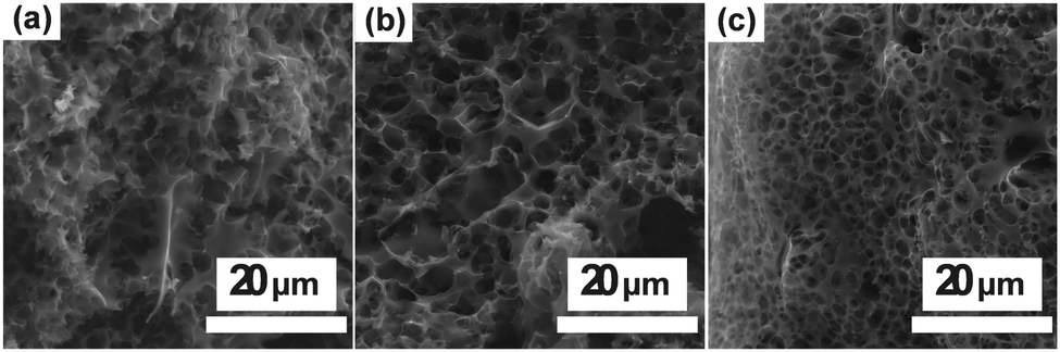
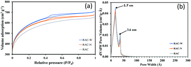
Fig. 1 shows SEM images of unirradiated ACs (RAC), and ACs irradiated in NH4OH (RAC-N), and in DI water (RAC-W). RAC, RAC-W and RAC-N contain networks of pores (2–20 nm diameter). Further investigations into the porosity of these materials were undertaken through N2 adsorption-desorption measurements at 77 K, with total surface area being calculated using the BET model and pore volume/size distributions being estimated through the BJH method as shown in Table 1. As shown in Fig. 2(a), RAC exhibits the adsorption isotherm type I (micropore structure, <2 nm), whereas RAC-W and RAC-N show type IV (mesopore structure, 2–50 nm) isotherms.32 However, hysteresis loops of type IV are found in RAC-W and RAC-N. These are due to capillary condensation resulting in narrow slit-like mesopores and internal voids of irregular shape, which implies that gamma irradiation at 25 kGy promotes destruction of part of the RAC microporous network. Notably, while surface areas increase slightly after gamma irradiation, pore size distributions are essentially unchanged from those of RAC (Fig. 2b).
 |
| | Fig. 1 SEM images of (a) RAC (b) RAC-W and (c) RAC-N. | |
Table 1 Surface properties of RAC, RAC-W and RAC-N investigated by BET and BJH methods
| Samples |
BET surface area (m2 g−1) |
Pore volume (cm3 g−1) |
Average pore diameter (nm) |
| RAC |
1749 |
1.00 |
2.7 |
| RAC-W |
1909 |
1.09 |
2.6 |
| RAC-N |
1856 |
1.04 |
2.6 |
 |
| | Fig. 2 (a) Nitrogen adsorption-desorption isotherm and (b) Pore size distribution plots for RAC, RAC-W and RAC-N. | |
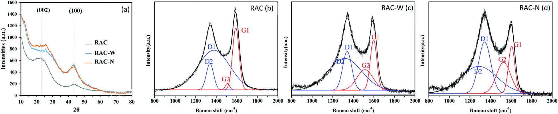
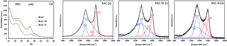
Fig. 3a shows the XRD patterns of RAC, RAC-W and RAC-N. Each pattern shows two broad peaks at 2θ ≈ 23° and 2θ ≈ 43° which correspond to the (002) and (100) planes of graphite, respectively. Notably, the (100) intensities of RAC-W and RAC-N are significantly greater than that of RAC which indicates that a higher degree of crystallinity occurs after gamma irradiation. The calculated d-spacings (002) of RAC, RAC-W and RAC-N are 0.3830, 0.3796 and 0.3770 nm, respectively.
 |
| | Fig. 3 (a) XRD patterns of RAC, RAC-W and RAC-N as well as Raman spectra of (b) RAC, (c) RAC-W, and (d) RAC-N. | |
As shown in Fig. 3b–d, Raman spectra of RAC samples exhibit two distinct bands, a graphite band (G) at ∼1600 cm−1 and a disorder-induced band (D) at ∼1350 cm−1. Notably, the intensity of the G band is lower than that of the D band after irradiation, as a result of structural changes. Also, an increase in ID/IG (Table 2) on irradiation indicates the induction of defects or disorder in the material structure,33,34 such as a change in the ratio of sp3/sp2 centres in the carbon domain.
| |  | (1) |
Table 2 Elemental content (data from XPS) and structural data (data from Raman spectroscopy) for RAC, RAC-W and RAC-N
| Samples |
I
D/IG |
I
D1/IG1 |
I
D2/IG2 |
I
G2/IG1 |
L
a (nm) |
| RAC |
0.84 |
0.58 |
1.52 |
0.34 |
7.53 |
| RAC-W |
1.07 |
0.81 |
1.34 |
0.53 |
5.41 |
| RAC-N |
1.17 |
1.07 |
0.92 |
0.72 |
4.11 |
Gaussian peak fitting of Raman spectra enables more detailed structural information to be obtained. As indicated in Fig. 3b–d, four peaks (G1, G2, D1 and D2) were fitted to each spectrum. A shift of the G1 band to higher wavenumber in RAC-W (∼1604 cm−1) and RAC-N (∼1603 cm−1) relative to RAC (1585 cm−1) could be attributed to contraction of the basal plane. The crystallite sizes (La) in RAC materials were calculated using eqn (1) and are listed in Table 2. These results agree with the shifting of G1 peaks on irradiation, as the crystallite sizes of RAC-W and RAC-N decrease significantly relative to those of RAC. The ID1/IG1 ratio is related to the amount of amorphous carbon, and as such an increase in ID1/IG1 on irradiation reflects a loss of carbon crystallinity. Furthermore, the IG2/IG1 ratio is indicative of the number of carbon clusters in the sample, and results after irradiation suggest that RAC-W and RAC-N contain significantly greater amounts of carbon clusters than RAC. Gamma irradiation at 25 kGy in media (DI water and NH4OH) thus causes microcrystalline structural changes in RAC, with disordered carbon was reported previously that can facilitate electrolyte ion penetration and therefore increase the storage properties of the batteries.24,35
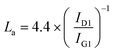
Chemical compositions of RAC samples were obtained using XPS. As indicated in Table 3, nitrogen and oxygen content are profoundly lower in irradiated samples compared with those of RAC. The devolution C1s peak of RAC (Fig. 4a), RAC-W (Fig. 4d), and RAC-N (Fig. 4d) appears as four components. The fitted peaks at 284.5, 285.2, 286.9, and 289.2 eV relate to contributions from C–C (sp2), C–(C, H) (sp3), C–(O, N) (alcohol), and C![[double bond, length as m-dash]](https://www.rsc.org/images/entities/char_e001.gif) O (carbonyl, quinones aldehyde and ketones) centres.36–39 The fitted O 1s of RAC (Fig. 4b), RAC-W (Fig. 4e) and RAC-N (Fig. 4h) has two components, at 531–532 eV and 533–534 eV. These can be attributed to arising from C–O and CO, respectively.36–39 Additionally, the devolution N 1s peak of RAC, Fig. 4c, shows two prominent peaks from the presence of pyrrolic (400.2 eV, C–(NH)–C) and graphitic nitrogen (401.9 eV) centres.36–39 After gamma irradiation, RAC-W (Fig. 4f) and RAC-N (Fig. 4h) show two nitrogen components: those of pyrrolic (∼400 eV) and pyridinic (∼399 eV) centres.36–39 Notably, no graphitic nitrogen was found in RAC-W and RAC-N. Graphitic nitrogen (sp2 hybridization) arises from the presence of these atoms in aromatic rings within graphene layers. Gamma irradiation at 25 kGy promotes rupturing of graphitic N structures and rearrangement to form pyrrolic and pyridinic nitrogen centres.40 In addition, a decrease in nitrogen content may be due to release of nitrogen and nitrogen oxides, which also occurs in pyrolysis and carbonization processes.37–39
O (carbonyl, quinones aldehyde and ketones) centres.36–39 The fitted O 1s of RAC (Fig. 4b), RAC-W (Fig. 4e) and RAC-N (Fig. 4h) has two components, at 531–532 eV and 533–534 eV. These can be attributed to arising from C–O and CO, respectively.36–39 Additionally, the devolution N 1s peak of RAC, Fig. 4c, shows two prominent peaks from the presence of pyrrolic (400.2 eV, C–(NH)–C) and graphitic nitrogen (401.9 eV) centres.36–39 After gamma irradiation, RAC-W (Fig. 4f) and RAC-N (Fig. 4h) show two nitrogen components: those of pyrrolic (∼400 eV) and pyridinic (∼399 eV) centres.36–39 Notably, no graphitic nitrogen was found in RAC-W and RAC-N. Graphitic nitrogen (sp2 hybridization) arises from the presence of these atoms in aromatic rings within graphene layers. Gamma irradiation at 25 kGy promotes rupturing of graphitic N structures and rearrangement to form pyrrolic and pyridinic nitrogen centres.40 In addition, a decrease in nitrogen content may be due to release of nitrogen and nitrogen oxides, which also occurs in pyrolysis and carbonization processes.37–39
Table 3 Chemical composition of RAC, RAC-W and RAC-N investigated by XPS
| Sample |
Total % C |
% Components |
Total % O |
% Components |
Total % N |
% Components |
| C1 (C sp2) (∼284 eV) |
C2 (C sp3) (∼285 eV) |
C3 (C–O,N) (∼287 eV) |
C4 (CO) (∼289 eV) |
O1 (C–O) (∼532 eV) |
O2 (CO) (∼534 eV) |
Graphitic (∼402 eV) |
Pyrrolic (∼400 eV) |
Pyridinic (∼399 eV) |
| RAC |
90.24 |
34.18 |
24.95 |
17.43 |
13.69 |
8.27 |
4.63 |
3.64 |
1.48 |
1.12 |
0.37 |
— |
| RAC-W |
92.51 |
32.93 |
28.23 |
14.37 |
16.98 |
6.83 |
6.14 |
0.69 |
0.66 |
— |
0.38 |
0.44 |
| RAC-N |
93.40 |
32.93 |
33.62 |
19.18 |
7.67 |
5.85 |
3.04 |
2.81 |
0.75 |
— |
0.39 |
0.36 |
 |
| | Fig. 4 High-resolution XPS spectra of (a–c) RAC, (d–f) RAC-W, and (g–h) RAC-N. | |
Electrochemical properties of LSBs
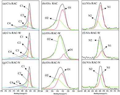
Electrochemical performances of as-fabricated LSBs were further tested by galvanostatic charge-discharge (GCD). Fig. 5a shows the GCD scan of RAC-W and RAN-N compared with that of RAC. Three plateaus were observed in all scans during charge-discharge processes due to the multi-electron redox reaction at the sulfur/carbon cathode. The first plateau is due to reduction of S8 to Li2S4, at ∼2.3 V.8,41 The produced lithium polysulfides dissolve in the organic electrolyte.42 The second plateau takes place at ∼2.1 V. which polysulfides are reduced to low order polysulfides (Li2Sn, 2 < n < 4) and Li2S. The final plateau corresponds to further reduction of Li2S2 to Li2S (sharp slope) at the voltage less than 2.1 V. The specific capacities of RAC, RAC-W and RAC-N are 861, 1137 and 998 mA h g−1 at 0.1 C, respectively (Fig. 5a), which indicates that modification of RAC by gamma irradiation in water (RAC-W) and ammonia solution (RAC-N) can improve the LSBs performance.
 |
| | Fig. 5 (a) Galvanostatic charge/discharge profiles at 0.1C rate, (b) C-rate test, (c) Stability test of LSBs using RAC, RAC-W and RAC-N as active materials. | |
An effect of C-rates (0.1–2) on cathode performance was also investigated, with the results shown in Fig. 5b. Although at 0.1 C the specific capacitance of RAC-W is the highest, this material shows lower performance than RAC at high C-rates (0.5–2 C). The data suggests that insufficient binding sites of RAC cause capacity drop.19Fig. 5c shows stability tests of RAC, RAC-W and RAC-N at 0.1 C. The LBSs capacities using RAC-W as cathodes are approximately 100 mA h g−1 after 350 cycles. However, in RAC and RAC-N, the capacity drops to 100 mA h g−1 after 250 cycles.14 The better LSBs performance of RAC-W could be attributed to more effective chemical anchoring of polysulfides, which retards their dissolution in the electrolyte.43 In addition, the better LSB performance of RAC-W and RAC-N may correlate with the higher degree of disordered carbon in these cathode materials, which enhances electrolyte ion penetration.
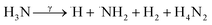
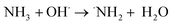
The evidence from this study indicates that gamma irradiation at 25 kGy can be used to modify the surface chemical properties of RAC and increasing the capacity of LSBs. Reactive oxidizing agents (HO˙, H2O2, O2) generated during water radiolysis (eqn (2)) can oxidize the C–OH moieties on RAC-W surfaces to carbonyls (CO)44,45 which results in sulfur anchoring and reduced shuttle effect rates. In the case of RAC-N the ˙NH2 oxidizing agent is generated from radiolysis in ammonium solution, as shown in eqn (3) and (4).46 The ˙NH2 thus reacts with RAC to form various nitrogen functional groups.47 The XPS results confirm that only pyrrolic and pyridinic N-centres form LiSnLi+⋯N bonds after irradiation, with other quaternary N atoms being ineffective for this purpose.8 It is in good agreement with higher specific capacity and stability of RAC-W which contain greater amount of pyrrolic an pyridinic nitrogen than that of RAC and RAC-N.
| |  | (2) |
| |  | (3) |
| |  | (4) |
Conclusions
The surface, chemical, and electrical properties of activated carbon derived from glutinous rice grains (RAC) were successfully modified by gamma radiolysis in water (RAC-W) and ammonia solution (RAC-N). The as-fabricated lithium-sulfur batteries (LSBs), using RAC-W and RAC-N as active materials in cathodes, show higher specific capacity (1137 and 998 mA h g−1, respectively) and stability (>150 cycles) than unirradiated RAC (861 mA h g−1). Although the surface areas and pore volumes of RAC did not change significantly after radiolysis, carbonyl groups (CO) and pyridinic nitrogen centres were created which play a crucial role in the anchoring of polysulfides, and thus reducing the shuttle effect.
Author contributions
S. A., P. L., K. S., S. M., T. U., and T. K; validation, S. A., P. L., K. S., S. M., T. U., and T. K; formal analysis, S. A., P. L., K. S., S. M., and T. K; investigation, S. A. and T. K; resources, S. A., P. L., K. S., S. M., T. U., and T. K; writing—original draft preparation, T. K.; writing review and editing, S. A. and T. K; visualization T. K. and S. A.; supervision, T. K; project administration, T. K; funding acquisition, T. K and S. A.
Conflicts of interest
There are no conflicts to declare.
Acknowledgements
We would like to thank Assoc. Prof. Dr Montree Sawangphruk and the Department of Energy Science and Engineering (ESE), Vidyasirimedhi Institute of Science and Technology, for the use of LSB battery testing facilities and technical support. We also would like to thank Assoc. Prof. Dr Christopher B. Smith for kind suggestions and language checking. This work was gratefully supported by Thailand Science Research and Innovation (TSRI).
Notes and references
- Y. Bayar, M. D. Gavriletea, S. Sauer and D. Paun, Sustainability, 2021, 13, 656 CrossRef CAS.
- A. Haldar and N. Sethi, Environ. Sci. Pollut. Res. Int., 2021, 28, 15485–15503 CrossRef CAS PubMed.
- A. A. Eladl, M. I. El-Afifi, M. A. Saeed and M. M. El-Saadawi, Int. J. Electric. Power Energy Systems, 2020, 117, 105719 CrossRef.
- O. Erixno, N. A. Rahim, F. Ramadhani and N. N. Adzman, Sustainable Energy Technol. Assessments, 2022, 51, 101944 CrossRef.
- A. Elia, M. Kamidelivand, F. Rogan and B. Ó. Gallachóir, Renewable Sustainable Energy Rev., 2021, 138, 110488 CrossRef.
- M. A. Hannan, A. Q. Al-Shetwi, R. A. Begum, P. Jern Ker, S. A. Rahman, M. Mansor, M. S. Mia, K. M. Muttaqi and Z. Y. Dong, J. Energy Storage, 2021, 42, 103040 CrossRef.
- C. Dong, W. Gao, B. Jin and Q. Jiang, iScience, 2018, 6, 151–198 CrossRef CAS.
- X. Fan, W. Sun, F. Meng, A. Xing and J. Liu, Green Energy Environ., 2018, 3, 2–19 CrossRef.
- P. Liu, Y. Wang and J. Liu, J. Energy Chem., 2019, 34, 171–185 CrossRef.
- F. D. R. Maharaj, W. Wu, Y. Zhou, L. T. Schwanz and M. P. Marshak, J. Chem. Educ., 2019, 96, 3014–3017 CrossRef CAS.
- M. Rana, S. A. Ahad, M. Li, B. Luo, L. Wang, I. Gentle and R. Knibbe, Energy Storage Mater., 2019, 18, 289–310 CrossRef.
- W. Ren, W. Ma, S. Zhang and B. Tang, Energy Storage Mater., 2019, 23, 707–732 CrossRef.
- L. Fan, S. Chen, J. Zhu, R. Ma, S. Li, R. Podila, A. M. Rao, G. Yang, C. Wang, Q. Liu, Z. Xu, L. Yuan, Y. Huang and B. Lu, Adv. Sci., 2018, 5, 1700934 CrossRef.
- L. Zhou, D. L. Danilov, R.-A. Eichel and P. H. L. Notten, Adv. Energy Mater., 2021, 11, 2001304 CrossRef CAS.
- Z.-L. Xu, J.-K. Kim and K. Kang, Nano Today, 2018, 19, 84–107 CrossRef CAS.
- S. Wang, K. Zou, Y. Qian, Y. Deng, L. Zhang and G. Chen, Carbon, 2019, 144, 745–755 CrossRef CAS.
- A. B. Fuertes and M. Sevilla, ChemSusChem, 2015, 8, 1049–1057 CrossRef CAS PubMed.
- M. Zheng, Q. Hu, S. Zhang, H. Tang, L. Li and H. Pang, Appl. Sci., 2017, 7, 1036 CrossRef.
- J. Wutthiprom, N. Phattharasupakun and M. Sawangphruk, Carbon, 2018, 139, 945–953 CrossRef CAS.
- K. Xiang, S. Cai, X. Wang, M. Chen and S. Jiang, J. Alloys Compd., 2018, 740, 687–694 CrossRef CAS.
- Z. Song, X. Lu, Q. Hu, J. Ren, W. Zhang, Q. Zheng and D. Lin, J. Power Sources, 2019, 421, 23–31 CrossRef CAS.
- H. Liu, J. Zhang, H. H. Ngo, W. Guo, H. Wu, C. Cheng, Z. Guo and C. Zhang, RSC Adv., 2015, 5, 52048–52056 RSC.
- L. Deng, B. Lu, J. Li, G. Lv, S. Du, J. Shi and Y. Yang, Fuel, 2017, 200, 54–61 CrossRef CAS.
- P. González-García, Renew Sustain Energy Rev., 2018, 82, 1393–1414 CrossRef.
- Y. J. Lee, H. W. Park, U. G. Hong and I. K. Song, Curr. Appl. Phys., 2012, 12, 1074–1080 CrossRef.
- K. Kanjana, P. Harding, T. Kwamman, W. Kingkam and T. Chutimasakul, Biomass Bioenergy, 2021, 153, 106206 CrossRef CAS.
- X. Zhang, S. Zhang, H. Yang, Y. Feng, Y. Chen, X. Wang and H. Chen, Chem. Eng. J., 2014, 257, 20–27 CrossRef CAS.
- K. Wechakorn, P. Sangangam, N. Puengposop, P. Lertsarawut and T. Kwamman, Orient. J. Chem., 2020, 36, 897–902 CAS.
- T. Chutimasakul, T. Phonlam, V. Chobpattana, P. Lertsarawut, W. Kingkam, S. Laksee and T. Kwamman, Key Eng. Mater., 2021, 904, 407–412 Search PubMed.
- T. Kwamman, T. Chutimasakul, P. Sangangam, N. Puengposop and K. Wechakorn, J. Met., Mater. Miner., 2021, 31, 123–128 CAS.
- P. Lertsarawut, T. Rattanawongwiboon, T. Tangthong, S. Laksee, T. Kwamman, B. Phuttharak, P. Romruensukharom, P. Suwanmala and K. Hemvichian, Polymers, 2021, 13, 1314 CrossRef CAS.
- K. Chen, T. Zhang, X. Chen, Y. He and X. Liang, Pet. Explor. Dev., 2018, 45, 412–421 CrossRef.
- Y. Wang, D. C. Alsmeyer and R. L. McCreery, Chem. Mater., 1990, 2, 557–563 CrossRef CAS.
- A. C. Ferrari and J. Robertson, Phys. Rev. B: Condens. Matter Mater. Phys., 2000, 61, 14095–14107 CrossRef CAS.
- N. M. Keppetipola, M. Dissanayake, P. Dissanayake, B. Karunarathne, M. A. Dourges, D. Talaga, L. Servant, C. Olivier, T. Toupance, S. Uchida, K. Tennakone, G. R. A. Kumara and L. Cojocaru, RSC Adv., 2021, 11, 2854–2865 RSC.
- M. Ayiania, M. Smith, A. J. R. Hensley, L. Scudiero, J.-S. McEwen and M. Garcia-Perez, Carbon, 2020, 162, 528–544 CrossRef CAS.
-
R. C. Bansal and M. Goyal, Activated Carbon Adsorption, CRC Press, 2005 Search PubMed.
- S. S. Shazali, A. Amiri, M. N. Mohd Zubir, S. Rozali, M. Z. Zabri and M. F. M. Sabri, Mater. Res. Express, 2018, 5, 059601 CrossRef.
- L. Sun, L. Wang, C. Tian, T. Tan, Y. Xie, K. Shi, M. Li and H. Fu, RSC Adv., 2012, 2, 4498–4506 RSC.
- J. D. Bagley, D. K. Kumar, K. A. See and N.-C. Yeh, RSC Adv., 2020, 10, 39562–39571 RSC.
- M. Semeniuk, Z. Yi, V. Poursorkhabi, J. Tjong, S. Jaffer, Z.-H. Lu and M. Sain, ACS Nano, 2019, 13, 6224–6255 CrossRef CAS PubMed.
- L. Yang, Q. Li, Y. Wang, Y. Chen, X. Guo, Z. Wu, G. Chen, B. Zhong, W. Xiang and Y. Zhong, Ionics, 2020, 26, 5299–5318 CrossRef CAS.
- C. Schneidermann, C. Kensy, P. Otto, S. Oswald, L. Giebeler, D. Leistenschneider, S. Grätz, S. Dörfler, S. Kaskel and L. Borchardt, ChemSusChem, 2019, 12, 310–319 CrossRef CAS PubMed.
- I. Velo-Gala, J. J. López-Peñalver, M. Sánchez-Polo and J. Rivera-Utrilla, Carbon, 2014, 67, 236–249 CrossRef CAS.
- L. Ji, M. Rao, H. Zheng, L. Zhang, Y. Li, W. Duan, J. Guo, E. J. Cairns and Y. Zhang, J. Am. Chem. Soc., 2011, 133, 18522–18525 CrossRef CAS PubMed.
- D. Cleaver, E. Collinson and F. S. Dainton, Trans. Faraday Soc., 1960, 56, 1640–1655 RSC.
- H. Li, J. Huang, F. Lu, Y. Liu, Y. Song, Y. Sun, J. Zhong, H. Huang, Y. Wang, S. Li, Y. Lifshitz, S.-T. Lee and Z. Kang, ACS Appl. Bio Mater., 2018, 1, 663–672 CrossRef CAS PubMed.
Footnote |
| † Passavorn Limmeechokchai, Kanok Sirilapyanonth and Sukpawat Moungsombat contributed equally in this work |
|
| This journal is © The Royal Society of Chemistry 2022 |
Click here to see how this site uses Cookies. View our privacy policy here. 
 Open Access Article
 This Open Access Article is licensed under a Creative Commons Attribution-Non Commercial 3.0 Unported Licence
 *c
*c