
 Open Access Article
 This Open Access Article is licensed under a
 Creative Commons Attribution 3.0 Unported Licence
Towards improved waterproofness of Mn4+-activated fluoride phosphors
Qiao
Qu†
,
Zhaowu
Wang†
 and
Haipeng
Ji
*
and
Haipeng
Ji
*
School of Materials Science and Engineering, Zhengzhou University, Zhengzhou 450001, China. E-mail: jihp@zzu.edu.cn
First published on 3rd March 2022
Abstract
The Mn4+-activated fluoride phosphor, typically K2SiF6:Mn4+, has become a renowned red-emitting phosphor for white light emitting diodes (LEDs) due to its sharp line-type luminescence spectrum peaking at ∼630 nm. However, fluoride phosphors exhibit a relatively poor water resistance as [MnF6]2− groups are prone to hydrolysis under humid conditions, which leads to the formation of Mn-(hydro)oxides causing a severe decrease of the luminescence efficiency. This review summarizes six strategies that have been employed to improve the waterproofness of Mn4+-doped fluoride phosphors, including organic coating, inorganic heterogeneous/homogeneous coatings, surface deactivation (reduction of surface Mn4+), preparation of single crystal phosphors, and other methods (solid solution, Nb5+ oxidation, structural rigidity-enhancement, etc.). The pros and cons of each strategy have been compared, and, finally, several perspectives, such as the development of single crystal phosphors with low solubility to achieve better waterproofness, have been proposed.
 Qiao Qu | Q. Qu is now a master student at Zhengzhou University, China. Her current research focuses on Mn4+-activated oxyfluoride red-emitting phosphors. |
 Zhaowu Wang | Z. Wang received his master's degree from the Henan University of Technology, China, in 2015. He is now a doctoral student under the supervision of Prof. Deliang Chen and Dr Haipeng Ji. His current research focuses on Mn4+-activated fluoride single crystal phosphors. |
 Haipeng Ji | Dr Haipeng Ji is an associate professor at School of Materials Science and Engineering, Zhengzhou University, China. He received his BSc and PhD degrees from the China University of Geosciences (Beijing). He has also studied in National Institute for Materials Science (Japan) and Kyoto University. He is now working in the field of inorganic photoluminescent materials. |
1. Introduction
Over the last decade, white light-emitting diodes (LEDs) have found their way into many critical applications from general lighting to backlights for liquid crystal displays. For phosphor-converted white LEDs, Eu2+-activated nitrides (e.g., Sr2Si5N8:Eu2+, CaAlSiN3:Eu2+, and Sr[LiAl3N4]:Eu2+), which exhibit a broad photoluminescence emission band, and Mn4+-activated fluorides, which exhibit a narrower emission band (composed of multiple peaks), are the two main classes of red-emitting phosphors used in blue LED pumped white lighting.Since the commercialization of the K2SiF6:Mn4+ (KSF) phosphor by GE Global Research (USA), intense interest has been aroused on developing new Mn4+-doped fluoride phosphors. KSF exhibits a broad absorption band in the blue spectral range due to the spin-allowed 4A2 → 4T2 transition of Mn4+, which overlaps the electroluminescence of the blue-emitting InGaN LED. It shows a series of line-type emission peaks from Stokes and anti-Stokes ν6/ν4/ν3 vibronic modes associated with Mn4+ 2E → 4A2 transition.1,2 Each of the luminescence lines is very narrow with a full width at half maximum of <5 nm. The zero phonon line emission at 620 nm of the Mn4+ 2E → 4A2 transition is weak in KSF, and the Stokes ν6 emission at 630 nm dominates the luminescence. The International Telecommunication Union proposed the use of monochromatic light at 630 nm, 532 nm and 467 nm for the red, green and blue primary colors for ultra-high definition television.3 Since KSF exhibits luminescence of saturated red with sharp peaks, the filtering loss caused by the color filter is limited, thus benefitting the display with a wide color gamut and high color purity.
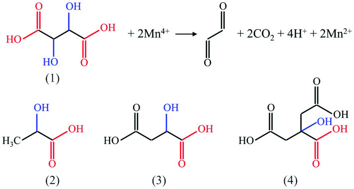
However, the main drawback of the fluoride phosphor is its sensitivity to moisture. Deterioration occurs easily due to water attack which causes the color change and lumen loss over time. This process gets accelerated when the phosphor is stressed by heat with temperatures up to ∼200 °C in high brightness LEDs. Deterioration of Mn4+-doped fluoride phosphors due to water attack lies in the hydrolysis of the [MnF6]2− group contained in the fluoride phosphors, especially those at the surface of the particles. The dissolution of the fluoride phosphor (reaction (1); A represents alkali metal ions such as K+, Na+, and Cs+, and M represents tetravalent cations such as Si4+, Ge4+, and Zr4+) generates the [MnF6]2− groups, which are prone to get hydrolysed into Mn-hydroxides and oxides,4 possibly viareactions (2) and (3). The water molecule could also take the place of fluorine forming KMnF4·H2O. This darkens the phosphor and severely weakens the intensity of red luminescence. It is thus critical to improve the waterproofness of Mn4+-activated fluoride phosphors.
| A2M1−xMnxF6(s) ↔ 2A+(aq.) + (1 − x)[MF6]2−(aq.) + x[MnF6]2− | (1) |
| [MnF6]2−(aq.) + 4H2O(l) → Mn(OH)4 (s, brown body color) + 4H+(aq.) + 6F−(aq.) | (2) |
| Mn(OH)4(s) → MnO2 (s, dark body color) + 2H2O(l) | (3) |
Various strategies have been reported to improve the waterproofness of fluoride phosphors, which are summarized in this review. The pros and cons of each strategy were compared, and, finally, the strategy of developing single crystal phosphors with low solubility to achieve improved waterproofness was highlighted.
2. Strategies to improve the waterproofness of Mn4+-doped fluoride phosphors
We classify the case reported strategies to prevent the deterioration of fluoride phosphors into six classes, i.e., organic coating, inorganic heterogeneous/homogeneous coating, surface deactivation, preparation of single crystal phosphors, and others.2.1 Organic coating
Coating with hydrophobic organic compounds is a frequently used method to improve the waterproofness of fluoride phosphors. Various organic compounds have been studied to build the encapsulant layer, including alkyl phosphates, oleic acid, silane coupling agents, polypropylene glycol, etc.In 2015, Nguyen et al.5 reported coating the KSF particles with a 50–100 nm thick alkyl phosphate layer, obtained via esterification of P2O5 with different alcohols. The KSF particles were dispersed in an organophosphate solution of alcohols, P2O5, and cross-linkers. Then, the suspension was evaporated at 50–70 °C and the obtained powder was washed and heated at 150 °C for 2 h. When using Al3+ as the cross-linker, the phosphors exhibited an excellent moisture resistance, retaining 87% of their initial external quantum efficiency (QE) after aging under 85 °C/85% RH (RH, relative humidity) conditions for one month. In 2017, Arunkumar et al.6 used oleic acid (OA) to encapsulate the KSF phosphor. OA and the phosphor were first dispersed in anhydrous ethanol, and the OA-passivated KSF (KSF-OA) was obtained by solvothermal treatment at 140 °C for 6 h. KSF-OA exhibits an internal QE of 68.1% without a decrease in the luminescence intensity compared with that of the pristine KSF. KSF-OA exhibits excellent moisture stability, retaining 85% of its initial luminescence intensity after aging for 450 h under 85 °C/85% RH conditions. The coating with OA is not detectable by X-ray diffraction (XRD) or scanning electron microscopy (SEM); only under the high-resolution transmission electron microscopy (TEM) observation, a layer with a thickness of 10 nm can be seen. As shown in Fig. 1a, the pristine KSF particles formed a brown solution after soaking in water (a phosphor concentration of 2.50 × 10⁵ ppm) within 5 min, while KSF-OA remained unchanged after 30 min. With a phosphor concentration of 6.25 × 10³ ppm and soaking in water for 15 days, the red emission of the KSF-OA sample still remained (Fig. 1b), while the emission of the pristine KSF was completely quenched. Images of the KSF and KSF-OA samples under visible and blue light excitation (λex = 450 nm) are shown in Fig. 1c. Besides, a large increase in the ionic conductivity (28% increase, 40 mS m−1) was detected for the uncoated KSF-soaked solution compared to a negligible increase in the ionic conductivity (∼1% increase, 2 mS m−1) for the KSF-OA case, which suggests the effective passivation effect of OA. FT-IR (Fourier transform infrared spectroscopy) and XPS (X-ray photoelectron spectroscopy) analyses indicate that hydrogen bonding (F⋯H) was formed between the fluorine in KSF and the hydrogen of the carboxyl group in OA (as illustrated in Fig. 1d). In addition, the bending configuration of the alkyl chain of the cis-form of OA ensures the complete encapsulation of KSF particles with a hydrophobic passivated skin.
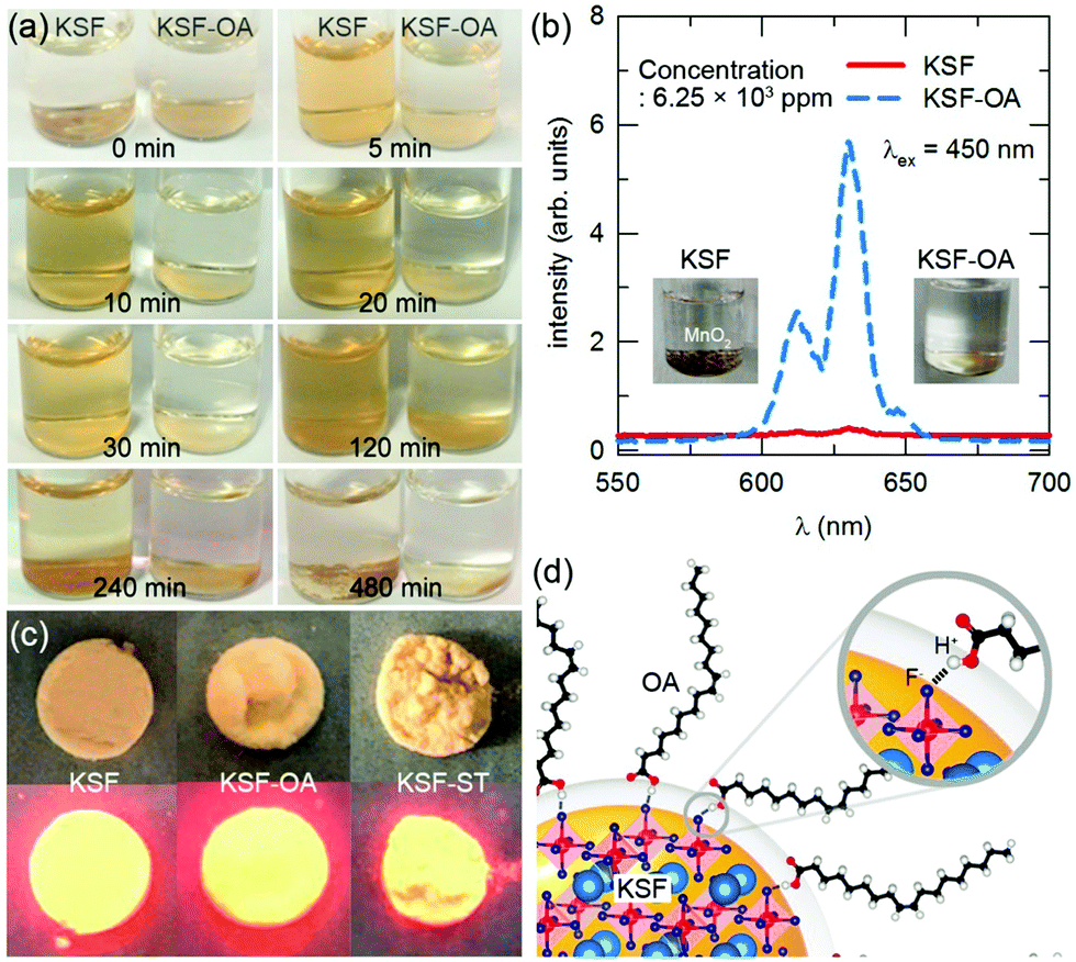 | ||
| Fig. 1 Moisture stability of the KSF-OA (KSF, K2SiF6:Mn4+; OA, oleic acid) phosphor. (a) Images of the pristine KSF and KSF-OA phosphors in deionized water at a concentration of 2.50 × 10⁵ ppm for over 4 h. (b) Luminescent emission spectra of pristine KSF and KSF-OA in deionization water at a concentration of 6.25 × 10³ ppm after 15 days. Inset shows the image of KSF and KSF-OA in water. A brown colored MnO2 was formed on KSF due to the hydrolysis of MnF62− in an aqueous medium, while the orange color is retained for KSF-OA even after 15 days. (c) Images of the pristine KSF, KSF-OA, and KSF-ST (KSF-ST is short for solvothermally treated KSF but without OA) phosphors under visible light (top layer) and blue light excitation (bottom layer). (d) Schematic of the hydrogen bonding between KSF and OA in the KSF-OA phosphor. The core elements, namely K, Si, and F, from the KSF phosphor and shell elements (C, O, and H) of the OA encapsulant are represented as pale blue, red, royal blue, gray, red, and white spheres, respectively. Reprinted with permission from ref. 6 Copyright 2017 American Chemical Society. | ||
In 2017, Kim et al.7 modified KSF with a silane coupling agent through the dry-type plasma-assisted method. The KSF powder was pre-treated with plasma to introduce hydroxyl (–OH) groups as chemical binding sites, and, then, it was modified with silanes that have different carbon chain lengths. The water contact angle of KSF increased from 6.64° to 71.92°, 79.04° and 122.47°, respectively, which indicates that the water-resistance was reinforced as the carbon chain length of silane increased. Besides, the modified KSF exhibited enhanced light absorption and quantum efficiency due to the formation of SiO2 coating and elimination of quenching sites. In 2018, Zhou et al.8 also used silane coupling agents to coat K2TiF6:Mn4+ at room temperature. The K2TiF6:Mn4+ powder was first processed using an ultraviolet lamp to increase hydroxyl (–OH) groups as chemical binding sites and then mixed vigorously with silane coupling agents with different lengths of alkyl chains. The water contact angle of the modified K2TiF6:Mn4+ dramatically increased from nearly 0° to 36.8°, 52.7°, 147.9°, or 155.4° after modification. The moisture resistance of the modified K2TiF6:Mn4+ was much better than that of the pristine K2TiF6:Mn4+, and the luminescence attenuated more slowly when the carbon chain of silane is longer.
In 2020, Hong et al.9 used polypropylene glycol (PPG) to coat BaGeF6:Mn4+. The PPG-coated BaGeF6:Mn4+ was prepared via co-precipitation during which PPG, together with GeO2, K2MnF6 and BaF2, were added into the HF solution. The luminescence intensity of the PPG-coated BaGeF6:Mn4+ was 11% higher than that of BaGeF6:Mn4+, which can be explained by the modification of the surface defects of BaGeF6:Mn4+ by PPG coating. After soaking in water for 120 h, the luminescence intensity of BaGeF6:Mn4+ decreased by 85%, while that of BaGeF6:Mn4+@PPG decreased by only 65%.
In 2020, Liu et al.10 used the chemical vapor deposition method to decompose acetylene on the K2SiF6:Mn4+ phosphor at high temperatures. The generated nanoscale amorphous carbon layer worked as a hydrophobic protective coating. K2SiF6:Mn4+@C retained 73% of the initial luminescence intensity after soaking in water for 8 h, while the pristine K2SiF6:Mn4+ retained only 0.7% of the initial value.
It is seen from the above literature references that organic encapsulation can greatly improve the hydrophobicity and waterproofness of fluoride phosphors. The organic molecules could form hydrogen bonding with fluorine of the fluoride phosphor for enhanced adhesion. Generally, high temperature treatment or pretreatment to introduce binding sites is necessary for effective organic coating.
2.2 Inorganic heterogeneous coating
Various kinds of inorganic compounds, mainly metal oxides and metal fluorides, have also been used as coating materials for fluoride phosphors. Examples hereof are SiO2, Al2O3, TiO2, CaF2, and SrF2.In 2019, Quan et al.11 coated KSF:Mn4+ with SiO2 (40–80 nm thick) via a sol–gel process. The phosphor was dispersed in a mixture of isopropanol, tetraethyl orthosilicate (TEOS) and oleic acid. After stirring, the mixture was rinsed with isopropanol and dried at 70 °C. The prepared KSF:Mn4+@SiO2 exhibited high thermal stability and excellent waterproof properties with a relative luminescence intensity of ∼65% after soaking for 1 h in water. In 2019, ten Kate et al.12 reported coating KSF:Mn4+ with a thin Al2O3 layer (3–25 nm) by atomic layer deposition (ALD) in a fluidized bed reactor. This ALD coating method is a gas-phase deposition technique based on self-limiting reactions. A layer-by-layer growth of the coating in the ALD process enables the precise control of the layer thickness by controlling the number of cycles. The coated product had a good water resistance and luminescence thermal stability. However, the use of water or ozone as the oxygen precursor during ALD caused degradation of the surface layer of KSF:Mn4+ particles. Hence, the ALD coating with Al2O3 is beneficial for waterproofness not to a conventional KSF:Mn4+ phosphor, but to a KSF:Mn4+ phosphor with a Mn-free shell. Besides, Smet et al.13 deposited Al2O3 or TiO2 on the surface of the KSF:Mn4+ phosphor also by the means of ALD. Fig. 2 shows the SEM-EDS (SEM, scanning electron microscopy; EDS, energy dispersive spectrometry) images of the Al2O3 or TiO2 deposited KSF:Mn4+. The Al2O3 layer suffered from delamination and blistering after deposition (Fig. 2a and b) due to incompatible chemistry between the KSF:Mn4+ core and the Al2O3 shell, while the TiO2 layer (with a thickness of ∼100 nm as observed by scanning transmission electron microscopy) could be grown with a high uniformity and conformality (Fig. 2c). A probable explanation13 of the observed delamination and blistering is the formation of volatile etch products such as AlFx(CH3)3−x by the interaction of trimethylaluminum molecules (precursors) with the fluoride substrate. Consequently, the aging test showed an enhanced stability for TiO2-coated KSF:Mn4+ compared with that for the pristine powder, whereas the Al2O3-coated particles showed an opposite trend (Fig. 2d) with a strong brown discoloration during aging due to the MnO2 formation.
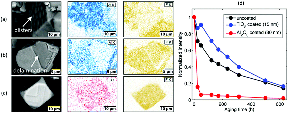 | ||
| Fig. 2 SEM-EDS images of the as-deposited radiofrequency plasma enhanced-ALD-deposited K2SiF6:Mn4+–Al2O3 showing (a) blistering and (b) delamination of the Al2O3 film. (c) SEM-EDS images of the thermal enhanced-ALD-deposited K2SiF6:Mn4+–TiO2. (d) Integrated phosphor emission for uncoated, Al2O3 or TiO2-coated phosphors as a function of aging time in 85 °C/85% RH. Reprinted with permission from ref. 13 Copyright 2019 American Chemical Society. | ||
In 2019, Dong et al.14 coated K2TiF6:Mn4+ (KTF) with CaF2. The CaF2 solution was added to a solution of K2TiF6/K2MnF6/HF, and the mixed solution was dried at 70 °C to obtain CaF2-coated KTF:Mn4+. After soaking in an ethanol–water (2![[thin space (1/6-em)]](https://www.rsc.org/images/entities/char_2009.gif) :3 by mass) solution, KTF dissolved immediately, accompanied by attenuation of the luminescence intensity, while KTF@CaF2 still emitted the bright red light after 150 min. Later, in 2021, Yu et al.15 coated KSF:Mn4+ with CaF2 by slowly adding a Ca(NO3)2 solution into the KSF:Mn4+/HF solution. After soaking in water for 6 h, the luminescence intensity of K2SiF6:0.055Mn4+ decreased to 41.68% of the initial one, while that of K2SiF6:0.055Mn4+@CaF2 (20 wt%) were retained 88.24% of the initial one. Similarly, Fang et al.16 coated KSF:Mn4+ with SrF2 by adding a Sr(NO3)2 solution to a K2TiF6:Mn4+/KHF2 solution. The luminescence intensities of KTF:Mn4+@xSrF2 (x = 0, 0.2, 0.4, 0.6, and 0.8) phosphors were still retained over 90% of initial values after soaking in water for 2 h.
:3 by mass) solution, KTF dissolved immediately, accompanied by attenuation of the luminescence intensity, while KTF@CaF2 still emitted the bright red light after 150 min. Later, in 2021, Yu et al.15 coated KSF:Mn4+ with CaF2 by slowly adding a Ca(NO3)2 solution into the KSF:Mn4+/HF solution. After soaking in water for 6 h, the luminescence intensity of K2SiF6:0.055Mn4+ decreased to 41.68% of the initial one, while that of K2SiF6:0.055Mn4+@CaF2 (20 wt%) were retained 88.24% of the initial one. Similarly, Fang et al.16 coated KSF:Mn4+ with SrF2 by adding a Sr(NO3)2 solution to a K2TiF6:Mn4+/KHF2 solution. The luminescence intensities of KTF:Mn4+@xSrF2 (x = 0, 0.2, 0.4, 0.6, and 0.8) phosphors were still retained over 90% of initial values after soaking in water for 2 h.
The coating with metal fluorides or oxides does not guarantee a hydrophobic shell like an organic coating does. For instance, the ALD-deposited Al2O3 or TiO2 shells are hydrophilic because of the presence of hydroxyl groups at the surface. Thus, the closure of the inorganic shell is critical for the improvement of waterproofness. To take advantage of the hydrophobic nature of organic coating, there are also some reports on integrated surface modification, for instance, using double-shell coatings of oleic acid and SiO2.17 Concerning the formation of a coating layer of inorganic metal fluorides, it is noted that high temperature treatment is not necessary.
2.3 Inorganic homogeneous coating
As early as in 2011, a patented approach was reported by Setlur et al.18 to improve the moisture stability of KSF:Mn4+ through surface encapsulation with a Mn4+-free K2SiF6 layer, which was obtained by treating KSF:Mn4+ with a mixture solution of K2SiF6/HF/H2SiF6. We call this method to obtain, for instance, KSF:Mn4+@KSF, as the homogeneous coating. This is different from the heterogeneous coating since this coating layer has absolutely the same physicochemical properties (such as the refractive index and lattice constants) as the inner phosphor. Besides, the homogeneous coating may decrease the non-radiative decay probability at the surface, enhancing the luminescence intensity.In 2019, Jiang et al.19 reported a K2SiF6 shell on the KSF:Mn4+ surface obtained by ethanol-induced deposition. KSF:Mn4+@KSF underwent almost no color change after soaking in water for 4 h, while KSF:Mn4+ turned quickly from yellow to light brown within 5 min. KSF:Mn4+@KSF retained 82% of the initial luminescence intensity after being soaked in water for 4 h, and retained 90% after being exposed under 85 °C/85% RH conditions for 10 days. In the same year, Huang et al.20 used a reverse cation exchange strategy to prepare the core–shell structured K2TiF6:Mn4+@K2TiF6. KTF:Mn4+ was added to a HF solution saturated with KTF crystals, and, then, the mixture was stirred for 20 min followed by vacuum filtration. KTF:Mn4+@KTF was obtained after repeating the procedures five times. The reverse cation exchange process did not change the morphology, particle size, and crystallographic structure of the phosphors. The Mn4+ distribution at the surfaces of KTF:Mn4+ and KTF:Mn4+@KTF was studied by positive secondary ion mass spectroscopy (SIMS), a technique that can analyze the chemical composition of solid surfaces at a depth of several nanometers. As seen in Fig. 3, the signal peak intensity ratios of Mn/Ti for KTF:Mn4+ and KTF:Mn4+@KTF were calculated to be about 0.19 and 0.03, respectively. Consistently, X-ray photoelectron spectroscopy (XPS) analysis indicated that the weight percentages of Mn on the KTF:Mn4+ and KTF:Mn4+@KTF surfaces were 0.16% and 0.09%, respectively. A concentration reduction of Mn at the shell led to improved water resistance property. As seen in Fig. 4, the yellow color of KTF:Mn4+ quickly became brown after soaking in water for 5 min, while KTF:Mn4+@KTF retained a yellow hue even after 300 min in water. Besides, after aging under 85 °C/85% RH conditions for 480 h, the luminescence intensities of the KTF:Mn4+@KTF and KTF:Mn4+ samples packaged in silicone retained approximately 89% and 45% of their initial values, respectively (Fig. 4f). LED2 fabricated using the phosphor blends of K2TiF6:Mn4+@K2TiF6 and YAG:Ce3+ showed a high luminous efficacy of 162 lm W−1 under 60 mA drive current (Fig. 4g), which retained 89% (144 lm W−1) with respect to the initial value after aging under 85 °C/85% RH conditions for 480 h, demonstrating robust stability (Fig. 4h).
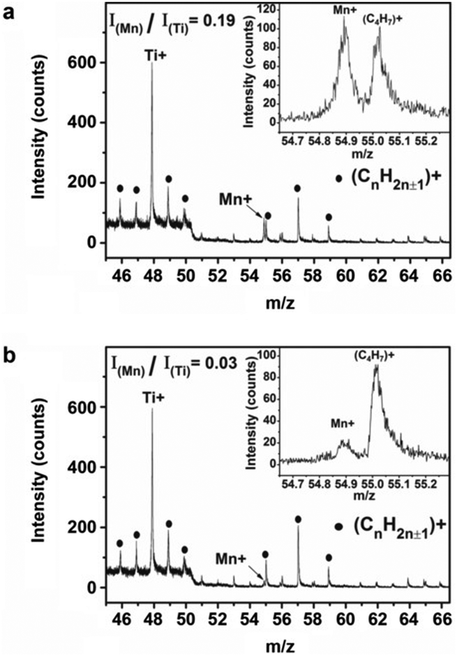 | ||
| Fig. 3 Positive secondary ion mass spectra of the (a) K2TiF6:Mn4+ and (b) K2TiF6:Mn4+@K2TiF6 phosphors; insets show the enlarged peak of Mn+. Other peaks (CnH2n±1+, solid dots) originated from the conductive tape used for fixing phosphor powders. Reprinted with permission from ref. 20 Copyright 2019 John Wiley and Sons. | ||
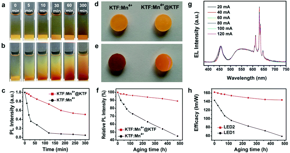 | ||
| Fig. 4 Photographs of the (a) K2TiF6:Mn4+@K2TiF6 and (b) K2TiF6:Mn4+ phosphors (both 0.15 g and with 7.00 at% Mn4+) soaked in deionized water (3 mL) for various durations. (c) Integrated luminescence intensities of the K2TiF6:Mn4+ and K2TiF6:Mn4+@K2TiF6 phosphors as a function of time in water. Photographs of the K2TiF6:Mn4+ and K2TiF6:Mn4+@K2TiF6 phosphor flakes (d) before and (e) after aging under 85 °C and 85% RH conditions for 480 h. (f) Integrated luminescence intensities of the K2TiF6:Mn4+ and K2TiF6:Mn4+@K2TiF6 phosphor flakes as a function of aging time. (g) Normalized electroluminescence spectra of LED2 (K2TiF6:Mn4+@K2TiF6 + YAG:Ce3+) under various drive currents in the range of 20–120 mA. (h) Luminous efficacies of LED1 (K2TiF6:Mn4+ + YAG:Ce3+) and LED2 as a function of aging time under 60 mA drive current. Reprinted with permission from ref. 20 Copyright 2019 John Wiley and Sons. | ||
Later in 2021, Li et al.21 reported that KSF:Mn4+@KSF exhibited an improvement in both water resistance and luminescence thermal stability. The homogeneously coated phosphor was prepared by adding KSF:Mn4+ into the HF solution dissolved with KSF. The integrated luminescence intensity of the composite phosphor retained 88% of the initial one after soaking in water for 1 day. Meanwhile, the integrated luminescence intensities at 120, 150, 180 and 210 °C were 176, 198, 214 and 213% of the initial one at 30 °C, respectively.
The homogeneous shell is seen to not only act as a shield for preventing H2O to hydrolyze the inner [MnF6]2− group, but also cut off the energy migration path to surface defects. The formation of the inert shell is mainly obtained by soaking the phosphor into a HF solution saturated with the host compound for epitaxial growth or Mn4+ ion reverse exchange.
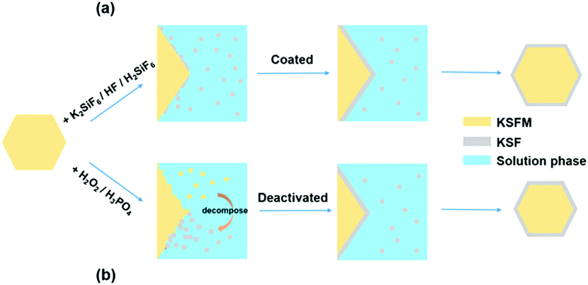
2.4 Surface deactivation
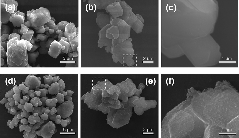
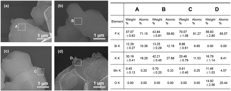
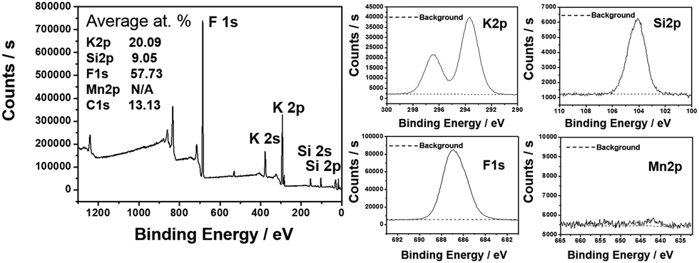
Besides homogeneous coating, the surface deactivation method was also developed to construct a Mn4+-free or Mn4+-rare shell. Reducing agents such as H2O2, DL-mandelic acid, H2C2O4, citric acid, thiourea, glucose, phenol, and polyethylene glycol have been reported to reduce the Mn4+ content on the phosphor surface.The first surface deactivation case was reported by Huang et al.22 in 2018 by treating K2SiF6:Mn4+ with a H2O2/H3PO4 solution. This method generates a core–shell-like structure similar to that obtained with the homogeneous coating method, as illustrated in Fig. 5. After soaking in water (solid-to-liquid ratio of 1 g/10 mL) for 6 h, the H2O2-treated water-resistant phosphor (denoted as WR-KSF:Mn4+) retained 76% of the initial luminescence intensity, while that of KSF:Mn4+ prepared by the ion exchange method (denoted as IE-KSF:Mn4+) steeply decreased down to 11%. Fig. 6 shows the SEM images of the two samples before and after soaking in water for 6 h. The WR-KSF:Mn4+ particles show a smooth surface and a particle size of about 10 μm (Fig. 6a). After soaking in water for 6 h, there is no significant difference in micromorphology even at high magnification (Fig. 6b and c). For IE-KSF:Mn4+, the original particles also showed a smooth surface (Fig. 6d), but they became more and more coarse as many nanoneedles appeared covering the surface after soaking (Fig. 6e and f). EDS analysis (Fig. 7) demonstrates that, for WR-KSF:Mn4+, the content of the surface Mn ions remained almost unchanged upon soaking in water, whereas the O content at either area A or area B is below the limit of detection. In comparison, the needle-like compounds that appeared on IE-KSF:Mn4+ after soaking do not contain any detective Si element but an excess of Mn, F, K, and especially O. Thus, the [MnF6]2− group suffered a process of dissolution and hydrolysis that led to the formation of manganese (hydro)oxide. Fig. 8 shows the surface element composition of WR-KSF:Mn4+ as revealed by XPS. There are only K, Si, and F atoms with atomic percentages close to 2:1:6, and there is no Mn signal, indicating the formation of a KSF:Mn4+@KSF core–shell structure, which is responsible for excellent waterproofness properties.
 | ||
| Fig. 5 Designing strategies for the K2SiF6:Mn4+@K2SiF6 core–shell structure: (a) homogeneous coating and (b) surface deactivation. Reprinted with permission from ref. 22 Copyright 2018 American Chemical Society. | ||
 | ||
| Fig. 6 SEM images of the H2O2-treated water-resistant K2SiF6:Mn4+: (a) before soaking in water and (b and c) after soaking in water for 6 h, and the SEM images of K2SiF6:Mn4+ prepared via the ionic exchange method: (d) before soaking in water and (e and f) after soaking in water for 6 h. Reprinted with permission from ref. 22 Copyright 2018 American Chemical Society. | ||
 | ||
| Fig. 7 SEM images and EDS results of the H2O2-treated water-resistant K2SiF6:Mn4+: (a, A) before soaking in water and (b, B) after soaking in water for 6 h, and the SEM images and EDS results of the K2SiF6:Mn4+ prepared via the ionic exchange method: (c, C) before soaking in water and (d, D) after soaking in water for 6 h. Reprinted with permission from ref. 22 Copyright 2018 American Chemical Society. | ||
 | ||
| Fig. 8 X-ray photoelectron spectra (XPS) and high-resolution XPS of K 2p, Si 2p, F 1s, and Mn 2p of H2O2-treated water-resistant K2SiF6:Mn4+. Reprinted with permission from ref. 22 Copyright 2018 American Chemical Society. | ||
In 2018, Huang et al.4 used DL-mandelic acid as a reductive agent to treat K2GeF6:Mn4+. For the pristine K2GeF6:Mn4+, the body color quickly turned into deep brown after soaking in water for 1 h with a solid-to-liquid ratio of 1 g/10 mL, while the DL-mandelic acid-loaded K2GeF6:Mn4+ exhibited supreme moisture resistance which retained 98% of the initial luminescence intensity after soaking in water for 7 days. The improvement lies in that the surface-loaded DL-mandelic acid can in situ decompose Mn-oxides/hydroxides from the hydrolysate of [MnF6]2− into soluble salts.
In 2019, Zhou et al.23 reported the surface passivation of K2XF6:Mn4+ (X = Ti, Si, Ge) by H2O2 that was achieved via a redox reaction (reaction (4)). The surface Mn4+ ions of the phosphor were consumed by treating them with a H2O2 solution, and, then, a Mn4+-rare surface was formed, which could effectively realize the isolation between the inner Mn4+ and the ambient moisture. Moreover, the luminescence of the H2O-destroyed fluoride phosphors can be recovered with the addition of H2O2 due to the reaction between Mn4+-hydrolysates and H2O2.
| [MnF6]2−(aq) + 2H2O2(l) → Mn2+(aq) + O2 + 2H2O(l) | (4) |
In 2019, Jiang et al.24 used a H2C2O4 reducing solution to treat Rb2SnF6:Mn4+. The pristine Rb2SnF6:Mn4+ deteriorated rapidly after soaking in water with the body color turning brown, while the H2C2O4-treated Rb2SnF6:Mn4+ maintained high brightness. When the concentration of the H2C2O4 solution was 0.2 g/20 mL, the treated Rb2SnF6:Mn4+ obtained the highest luminescence intensity. Besides, compared with H2O2/H3PO4 treatment, H2C2O4 solution treatment resulted in a better water resistance. This can be caused by the different reducibility of the solutions. The standard electrode potential of H2O2/O2 (0.695 V) is higher than that of H2C2O4/CO2 (−0.49 V), and, thus, the reduction of Mn4+ in a H2O2/H3PO4 solution can be inadequate and a part of Mn4+ was hydrolyzed before being reduced to Mn2+. Though the hydrolysis products MnO2 or Mn3+ compounds can be further etched away by reduction, this caused a loosely deposited RbSnF6 shell, which was easily eroded by water. Later in 2020, Yu et al.25 also used a H2C2O4 solution to treat K2GeF6:Mn4+. The absorption efficiency and internal and external QEs of the treated phosphor were 75.7%, 62.4% and 47.3%, respectively, which are slightly lower than the values (78.4%, 70.1%, and 55.0%) for the pristine phosphor. After soaking in water (a phosphor-to-water ratio of 0.5 g/5 mL) for 5 h, the luminescence intensity of the H2C2O4-treated K2GeF6:Mn4+ was retained at 95.8% of the initial value, while the pristine one retained only 36.2%. The formation of the Mn4+-rare shell on the phosphor surface after H2C2O4 treatment was verified by XPS and EDS analyses, which inhibited the hydrolysis of the inner [MnF6]2− group. In 2020, Liu et al.26 used the H2C2O4 solution to recover the luminescence of the deteriorated K2SiF6:Mn4+ and K2TiF6:Mn4+. The luminescence intensity of the deteriorated K2SiF6:Mn4+ or K2TiF6:Mn4+ can be recovered to 103.68% or 162.59% of the original values, due to the removal of the dark-brown coating on the deteriorated phosphors and the reduction of surface defects and fine particles.
In 2021, Li et al.27 used a weak reducing agent solution (citric acid or oxalic acid) to modify and/or recover the CsNaGexSn1−xF6:Mn4+ phosphor. After soaking in water for 5 min, the phosphor became brown, which turned pale yellow and recovered to the initial brightness by soaking in a citric acid or an oxalic acid solution. In 2021, Jia et al.28 also used citric acid and oxalic acid to modify K3RbGe2F12:Mn4+. A Mn4+-rare shell formed on the surface of the treated phosphor, which improved the water resistance properties. Moreover, although the phosphor was quenched after soaking in water for 72 h, it got recovered to the initial brightness after soaking in the oxalic acid or citric acid solution for 2 min.
In 2021, Wan et al.29 reported a reduction-assisted surface recrystallization (RSRC) strategy to construct a Mn4+-free shell for K2SiF6:Mn4+. To construct this Mn-free shell, when the Mn4+-doped fluoride formed a saturated solution in HF reaching a dissolution–crystallization equilibrium, a reducing agent was added to the solution to remove Mn4+ ions, thus preventing Mn4+ from recrystallization. Typically, the reducing agent such as 0.4 g of TA (L-tartaric acid), 0.5 g of MA (DL-malic acid), 0.5 g of CA (citric acid), 0.1 g of AA (ascorbic acid), or 5 mL of LA (DL-lactic acid) was added to 5 mL of saturated K2SiF6 solution, and, then, 0.5 g of K2SiF6:Mn4+ was added to the above solution under stirring for 2 h. Finally, the solids were centrifuged, washed and dried at 60 °C for 4 h. After soaking in water for 360 h, the luminescence intensity of the RSRC-treated K2SiF6:Mn4+ was retained at 94% of the initial intensity, exhibiting superior waterproofness. The reducibility of TA, etc., plays a key role in constructing the core–shell structure. TA is one of the α-hydroxy acids that has two carboxyl groups (–COOH) at the end and two hydroxyl groups (–OH) at the α position. The Mn4+ ion is considered as a strong oxidant due to its high standard electrode potential (ϕΘ = 1.64 eV) of Mn4+/Mn2+. In the HF solution, the hydroxyl groups of TA are easily oxidized to carbonyl groups (–CO–) and Mn4+ is reduced to Mn2+ (as illustrated in Fig. 9). The other α-hydroxy acids (lactic acid (LA), malic acid (MA) and citric acid (CA)) can also effectively eliminate Mn4+ on the fluoride surface in a similar manner.
 | ||
| Fig. 9 Structural formulae of four α-hydroxy acids: (1) tartaric acid, (2) lactic acid, (3) malic acid, and (4) citric acid, and the possible redox reaction between the tartaric acid and Mn4+ ion. Reprinted with permission from ref. 29 Copyright 2021 Elsevier. | ||
The strategy of constructing a deactivated layer with surface reduction of Mn4+ can evidently improve the waterproofness of fluoride phosphors. The reported reducing agents include both organic and inorganic ones with varying reducing powers. Among them, H2O2 will induce valence reduction not only of Mn4+ but also of Ti4+, causing an unexpected chromogenic reaction.23 Thus, H2O2 is not an appropriate surface deactivation agent for any fluotitanate phosphors. However, a drawback of the surface deactivation method is a lowered absorption efficiency due to the Mn4+ reduction.
2.5 Preparation of single crystal phosphors
The hydrolysis of [MnF6]2− mainly occurs at the phosphor surface. Since the specific surface area of a single crystal bulk phosphor is smaller than that of the corresponding micropowder and the number of Mn4+ ions at the interface is less, the single crystal phosphor is better able to sustain the deterioration by water. In addition, a single crystal has fewer defects, high crystallinity, and also high thermal conductivity that facilitates the heat dissipation of LED devices. It is thus beneficial to prepare single crystal phosphors with dimensions larger than a few micrometers.In 2016, Adachi et al.30 prepared Rb2XF6:Mn4+ (X = Si, Ti) single crystal phosphors (a size of ∼0.5 mm) by the co-precipitation method. A mixed solution of XO2, RbCO3, KMnO4 and HF was left in the dark for a few days to grow the bulk phosphors. The QE (λex = 475 nm) reached 92% for the Rb2TiF6:Mn4+ single crystal phosphor. Later, in 2018, they31 also reported the growth of Rb2GeF6:Mn4+ single crystal phosphor with a basal plane diameter of >2 mm via a similar co-precipitation growth method, and the QE for the bulk ingot was 87% (λex = 475 nm).
In 2019, Wang et al.32 prepared Cs2XF6:Mn4+ (X = Ge, Si, Ti) single crystal phosphors (sizes of ∼5 mm). Typically, 25 mmol GeO2, H2SiF6 or H2TiF6, 60 mmol CsF and 1 mmol K2MnF6 were dissolved in 40 mL of HF (40 wt%) at room temperature, and the Cs2XF6:Mn4+ single crystals grew from the solution after ten days. The external QEs of single crystals are as high as 66.9% (X = Ge), 63.2% (X = Si) and 52.8% (X = Ti), respectively, which are significantly higher than the data, 37.7%, 37.9%, and 32.2%, respectively, measured for the powder samples obtained by grinding the corresponding single crystals. The water resistance of single crystals is better than that of their ground powders. As shown in Fig. 10, after the Cs2GeF6:Mn4+ crystal had been soaked in water for 7 h, the body color did not change obviously, and it maintained 81% of the initial luminescence intensity. On the other hand, the body color of the corresponding ground powder gradually became black, and only 9% of the initial intensity was retained after 7 h of soaking.
 | ||
| Fig. 10 Luminescence intensities of Cs2GeF6:Mn4+ crystals and powders measured after soaking in deionized water for different durations. Reprinted with permission from ref. 32 Copyright 2019 John Wiley and Sons. | ||
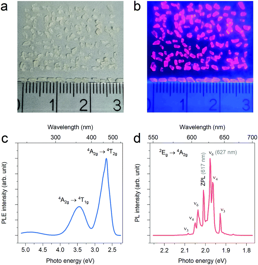
In 2020, Deng et al.33 prepared (NH4)2SiF6:Mn4+ and (NH4)3SiF7:Mn4+ single crystals. First, undoped crystals of (NH4)2SiF6 (sizes of 1–5 mm) and (NH4)3SiF7:Mn4+ (sizes of 3–8 mm) were grown in the saturated solutions by H2O evaporation for over two days. Then, the NH4HF2 solution dissolved with K2MnF6 was injected to the above crystals, and the (NH4)2SiF6:Mn4+ and (NH4)3SiF7:Mn4+ crystals were obtained after a fast ion-exchange within one minute. In 2021, we34 also prepared the Na2SiF6:Mn4+ single crystal phosphor. The millimeter-sized Na2SiF6 single crystals with a uniform columnar morphology (2–3 mm in length) were first grown in solution by slow cooling from 90 °C to 20 °C in a water bath, which were then soaked in the HF solution dissolved with K2MnF6 to implement Mn4+ doping via the cation exchange process (Fig. 11a and b). Under λex = 450 nm, the Na2SiF6 single crystals doped with Mn4+ exhibit a series of discrete sharp peaks with the intense zero phonon line emission at 617 nm (Fig. 11c and d). It was observed that, for the as-grown Na2SiF6 single crystals, the cation exchange reaction for Mn4+ doping is not effective and accompanied by by-reactions.
 | ||
| Fig. 11 Digital images of the Na2SiF6 crystals doped with Mn4+: (a) under daylight and (b) under 365 nm ultraviolent (UV) light. The photoluminescence excitation (monitoring for 627 nm emission) and emission (under 450 nm excitation) spectra were shown in (c) and (d), respectively. Reprinted with permission from ref. 34 Copyright 2021 John Wiley and Sons. | ||
In 2020, Zhou et al.35 grew K2SiF6:Mn4+ single crystals using a saturated crystallization method. As the growth time increased from 6 h to 4 days, the average size of the KSF:Mn4+ crystals increased from 200 μm to 1 mm, and, meanwhile, since [MnF6]2− in the solution was gradually exhausted, the subsequent growth formed a Mn4+-rare layer. The external QE of the KSF:Mn4+ single crystal reached as high as 78.2%, compared to 67.5% for the corresponding co-precipitated powder phosphor. Besides, after being soaked in water for 12 h, the luminescence intensity of the KSF:Mn4+ single crystal was retained 97.6% of the initial value, while the powder phosphor could only retain 51.8%. When the KSF:Mn4+ single crystal was used in white LED devices, a higher lumen efficiency and better heat dissipation were achieved.
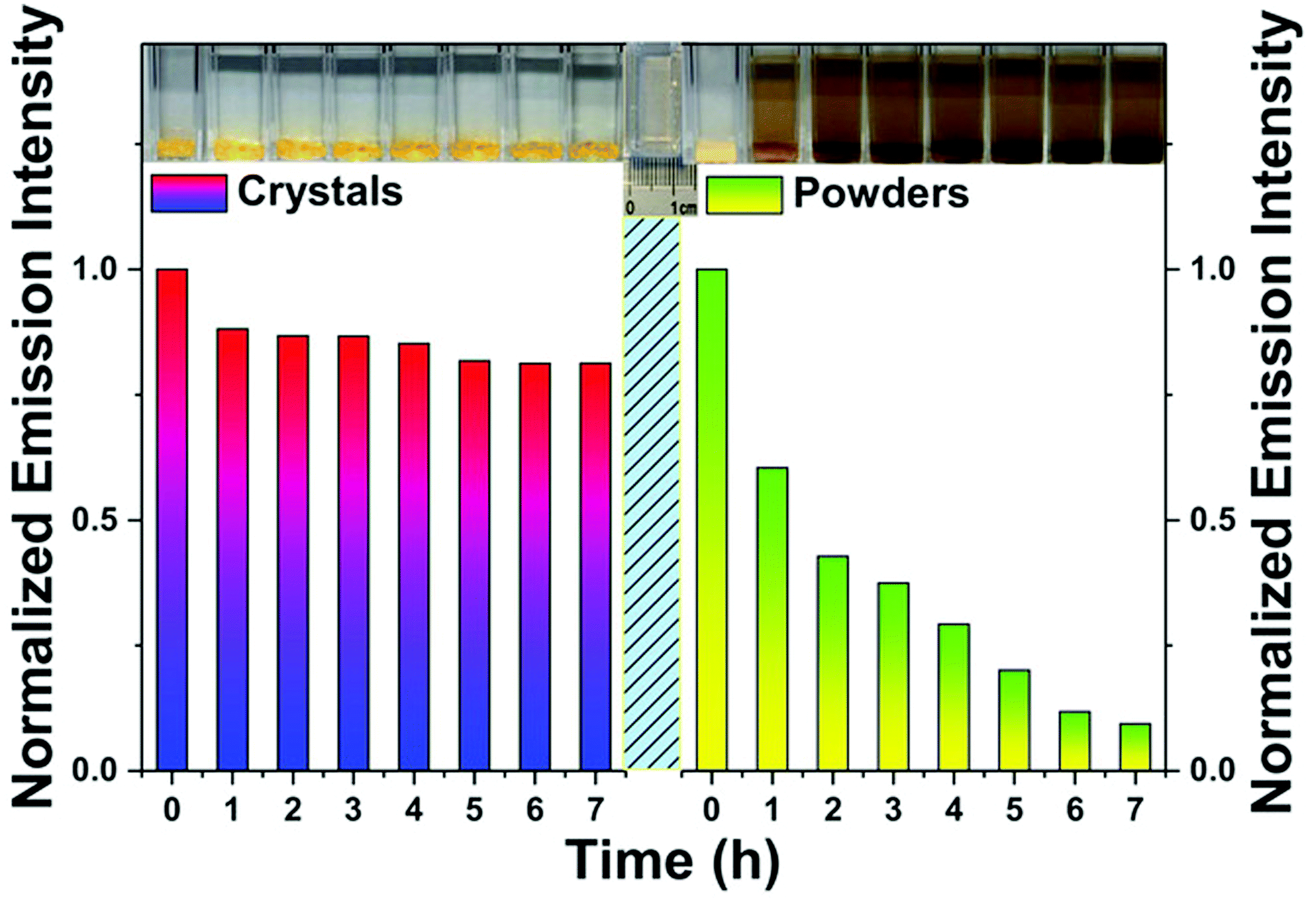
Later, in 2021, Zhou et al.36 prepared both the Cs2TiF6:Mn4+ and Cs2TiF6:Mn4+@Cs2TiF6 single crystals by solvent exchange and epitaxial growth at room temperature. The maximum size of the Cs2TiF6:Mn4+ single crystal was about 11.0 mm × 3.5 mm × 1.5 mm, and the luminescence intensity was about 3.6 times that of the corresponding polycrystalline powder. The internal QE was as high as 98.7%, which is almost three times of the corresponding polycrystalline powder (30.5%). The Cs2TiF6:Mn4+ single crystal was still yellow after 48 h of aging under 85 °C/85% RH conditions, and retained almost 100% of the initial luminescence intensity, while, after aging for 6 h under 85 °C/85% RH conditions, the color of the polycrystalline powder changed rapidly from yellow to brown, and the luminescence intensity quickly decreased to 10% of the initial value. As shown in Fig. 12A, after these single crystals were soaked in water for 10 min, Cs2TiF6:Mn4+ changed from yellow to brown, while Cs2TiF6:Mn4+@Cs2TiF6 remained yellow even after being soaked for 5 h. The luminescence intensity of Cs2TiF6:Mn4+ decreased monotonically with time (Fig. 12B), while Cs2TiF6:Mn4+@Cs2TiF6 retained a much higher luminescence intensity. This demonstrates that the core–shell structure can effectively improve the water resistance. Besides, the luminescence intensity evolution of the Cs2TiF6:Mn4+@Cs2TiF6 single crystal phosphor in water exhibited a unique three-step evolution (Fig. 12C–E). The initial decrease of the luminescence intensity over time is due to the reduced transparency of the CTF shell. The following increase is due to the fact that the CTF shell has become thinner over time, which is beneficial for the light propagation from the inner CTFM core. The last decrease is in a same manner with that of Cs2TiF6:Mn4+ shown in Fig. 12B, due to deterioration of the inner Cs2TiF6:Mn4+ core.
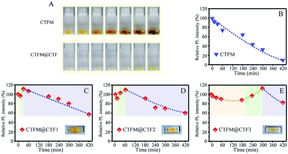 | ||
| Fig. 12 (A) Photographs of Cs2TiF6:Mn4+ and Cs2TiF6:Mn4+@Cs2TiF6 single crystals at different soaking periods in deionized water and integrated PL intensities of (B) Cs2TiF6:Mn4+, (C) Cs2TiF6:Mn4+@Cs2TiF6-1 (CTFM@CTF1), (D) Cs2TiF6:Mn4+@Cs2TiF6-2 (CTFM2), and (E) Cs2TiF6:Mn4+@Cs2TiF6-3 (CTFM@CTF3) single crystals as a function of soaking period in deionized water. The insets show the photographs of Cs2TiF6:Mn4+@Cs2TiF6 single crystals with different CTF shell thicknesses: CTF1 < CTF2 < CTF3. Note: the yellow colored part is the Cs2TiF6:Mn4+ core and the colorless part is the Cs2TiF6 shell. Reprinted with permission from ref. 36 Copyright 2021 John Wiley and Sons. | ||
These studies demonstrate that single crystal fluoride phosphors show superior water resistance properties compared to the powder phosphor, and a high-quality bulk ingot can be readily prepared under facile conditions due to the ionic bonding nature of fluorides. Besides, a Mn4+-free shell can also be grown on the Mn4+-doped single crystals for further shielding. To date, the reported maximum size of the single crystal phosphor is still around 1 mm, and the crystals are in various shapes (columns, granules, cubes, etc.) as the growth is restricted by the crystal structure. The applicability of these single crystal phosphors with various sizes and shapes in the all-inorganic encapsulated white LEDs needs an in-depth investigation. Moreover, the maximum Mn4+-doping concentration in different compositions of fluoride single crystals is left to be unknown.
2.6 Other methods
3. Summary and outlook
3.1 Summary
We reviewed in this paper the six classes of strategies for improving the waterproofness of fluoride phosphors, including organic coating, inorganic heterogeneous/homogeneous coating, surface deactivation, preparation of single crystal phosphors, and other methods.For organic coating, a uniform cover with precisely controlled thickness is easy to achieve and a dramatic increase of the water contact angle after organics modification can be used as an indication of achieving waterproof properties. The coating layer should be optically transparent and evenly cover the surface of individual phosphor particles to minimize the reduction of the luminous efficacy. Besides, the complexity of the coating process, the adhesion to the phosphor particles, and the tendency of the organic layer to decompose or oxidize at high temperatures are the problems that need to be addressed.
The inorganic heterogeneous coating layer, mainly metal fluorides (CaF2, SrF2, etc.) and oxides (SiO2, TiO2, etc.), is more stable at high temperatures and have stronger adhesion. In order not to affect the luminous performance, the inorganic layer needs to be transparent in the visible range and easily coated onto the surface. However, the coating with metal oxides like Al2O3 is more complex and the coating process such as atomic layer deposition causes a negative effect on the fluoride phosphors. Besides, the heterogeneous coating layer can partly absorb or scatter the incoming and outgoing radiation due to the difference in the refractive index and the lattice constant between the phosphor and the shell, reducing the luminescence efficiency of the phosphor. Thus, a very thin coating layer is preferred.
Homogeneous coating is a famous patented approach which is promising to prevent fluoride phosphors from the hydrolysis reaction. A homogeneous shell also cuts down the non-radiative decay probability at the surface and enhances the luminescence intensity of the mass. Moreover, homogeneous coating can be processed using a facile wet chemical method.
Similar to homogeneous coating, surface deactivation can also generate a Mn4+-rare or Mn4+-free shell which shields the inner [MnF6]2− group from the hydrolysis reaction. The deactivation can be easily achieved by treating fluoride phosphors with a solution containing a reducing agent such as H2O2 or H2C2O4.
The above strategies take advantage of post-treatments to enhance the waterproofness of fluoride phosphors. In comparison, the preparation of a single crystal phosphor generates bulk ingots with a lower specific surface area and less Mn4+ at the interface. Due to the fewer defects, the internal QE is quite often found to be higher than that of the corresponding powder phosphor. Besides, the as-grown single crystal phosphors can also be subjected to any of the aforementioned post-treatments to further enhance the waterproofness. Currently, the dominating methods for the single crystal preparation lie in the solvent volatilization and diffusion-in of poor solvents, and a new efficient method needs to be developed.
Finally, the reports employing other methods, like preparing solid solution phosphors to improve the waterproofness, are also inspiring. For example, these reports inspire to pay attention to these compositions with low solubility.
3.2 Outlook
The luminescence intensity measurement of a solid phosphor aggregate using a spectrometer is influenced by multiple factors, for example, the position/angle of the sample holder, the volume/packing of the phosphor, the stability of the excitation source (degradation, variation in the voltage or current), etc. Thus, it is a common experience that one will get a distinct luminescence intensity when measuring the same cuvette-containing phosphor aggregates twice using the same spectrometer. We recommend to measure the luminescence by placing a phosphor–water mixture-containing cuvette in an integrating sphere that is connected to a fiber optic spectrometer. Compared with a commercial spectrometer, this apparatus (illustrated in Fig. 13) is believed to get more reliable luminescence intensity by using an integrating sphere to collect the rays. Besides, as the base-located phosphor particles have contact with the cuvette and exhibit a lower hydrolysis kinetic than that of the upper surface of the phosphor aggregate which have contact with water, appropriate stirring of the phosphor suspension would help in the luminescence intensity measurement using this apparatus.
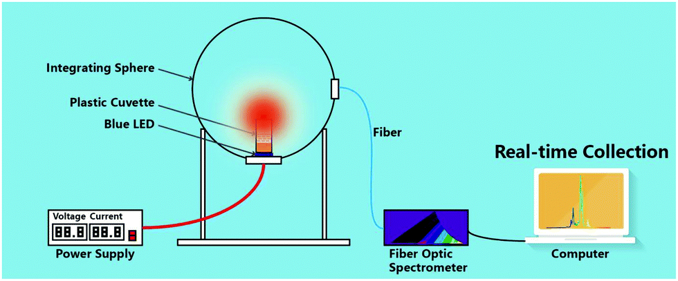 | ||
| Fig. 13 Schematic of an apparatus including an integrating sphere and a fiber optic spectrometer which is recommended for use to record the photoluminescence intensity during the deterioration evaluation of Mn4+-doped fluoride phosphors. Reprinted with permission from ref. 23 Copyright 2019 John Wiley and Sons. | ||
Moreover, in addition to the luminescence intensity measurement, it is also suggested to use the QE measurement to reveal the luminescence change and the Mn valence state characterization techniques (such as X-ray photoelectric spectroscopy and diffuse reflectance spectroscopy) to reveal the hydrolysis of [MnF6]2−. In addition to the monitoring of the luminescence intensity, the physicochemical change of the phosphor-soaked solution, for example, the absorbance and pH (the pH usually tends to decrease due to the ionization of F− of the fluoride phosphor), may reveal the hydrolysis of the fluoride phosphor and could be also used to evaluate the deterioration.
Finally, concerning the test method of aging in water, different phosphor-to-water ratios (often mass ratios) have been used, which makes it difficult to compare their waterproofness. As long as this aging method is widely used in the literature, it is appropriate to establish a testing standard, which, for example, sets a phosphor-to-water mass ratio for reference.
Fig. 14 compares the degradation of a silicone plate, a Y3Al5O12:Ce3+ single crystal, and a Cs2TiF6:Mn4+ single crystal by thermal aging at 150 °C. The silicone was initially colorless and then turned light yellow during aging, while the body colors of the Y3Al5O12:Ce3+ and Cs2TiF6:Mn4+ single crystals were not changed. The transmittance spectra showed that silicone had a serious decrease of transmittance and the absorption edge also showed an obvious red shift. Thus, the all-inorganic packaging free from any organic binders is a better choice, which also drives the interest of developing single crystal phosphors with suitable size.
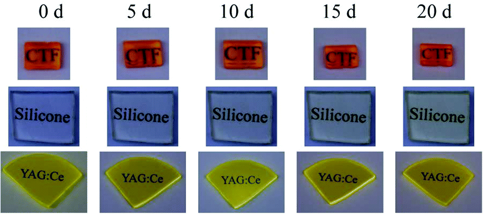 | ||
| Fig. 14 Photographs of the Cs2TiF6:Mn4+ single crystal, silicone, and Y3Al5O12:Ce3+ (YAG:Ce) crystal after heat treatment at 150 °C during different aging periods. Reprinted with permission from ref. 36 Copyright 2021 John Wiley and Sons. | ||
It is desired to prepare single crystal fluorides with low solubility such as alkali earth hexafluorides, which are, however, more complex. A similar solvent evaporation or diffusion-in of poor solvent treatment on a saturated solution will be encountered with a low yield problem since a saturated solution contains only a tiny amount of solute but a considerable volume of solvent. Some attempts have been recently reported. For example, the single crystal BaTiF6:Mn4+ phosphor with a length of 200–300 μm has been prepared at room temperature by fluoridation-induced epitaxial growth.42 More studies on the preparation of single crystal fluorides with low solubility are expected in future.
Conflicts of interest
The authors declare no conflicts of interest.Acknowledgements
This work was supported by the Key R&D and promotion projects in Henan Province (212102210180), the Provincial and Ministerial Co-construction of Collaborative Innovation Center for Resource Materials (zycl202005), the National Natural Science Foundation of China (51902291), the China Postdoctoral Science Foundation (2019M662524), the Postdoctoral Research Sponsorship in Henan Province (19030025) and the Young Talents Lifting Project from the Henan Association for Science and Technology (2022HYTP016).References
- L. Helmholz and M. E. Russo, J. Chem. Phys., 1973, 59, 5455–5470 CrossRef CAS
.
- A. G. Paulusz, J. Electrochem. Soc., 1973, 120, 942–947 CrossRef CAS
- Radiocommunication Sector of ITU (ITU-R), Parameter Values for Ultra-High Definition Television Systems for Production and International Programme Exchange, 2015.
- L. Huang, Y. Liu, S. Si, M. G. Brik, C. Wang and J. Wang, Chem. Commun., 2018, 54, 11857–11860 RSC
- H.-D. Nguyen, C. C. Lin and R.-S. Liu, Angew. Chem., Int. Ed., 2015, 54, 10862–10866 CrossRef CAS PubMed
- P. Arunkumar, Y. H. Kim, H. J. Kim, S. Unithrattil and W. Bin Im, ACS Appl. Mater. Interfaces, 2017, 9, 7232–7240 CrossRef CAS PubMed
- I. Jang, J. Kim, H. Kim, W.-H. Kim, S.-W. Jeon and J.-P. Kim, Colloids Surf., A, 2017, 520, 850–854 CrossRef CAS
- Y.-Y. Zhou, E.-H. Song, T.-T. Deng and Q.-Y. Zhang, ACS Appl. Mater. Interfaces, 2018, 10, 880–889 CrossRef CAS PubMed
- F. Hong, H. Xu, G. Pang, G. Liu, X. Dong and W. Yu, Chem. Eng. J., 2020, 390, 124579 CrossRef CAS
- Y.-X. Liu, J.-X. Hu, L.-C. Ju, C. Cai, V.-B. Hao, S.-H. Zhang, Z.-W. Zhang, X. Xu, X. Jian and L.-J. Yin, Ceram. Int., 2020, 46, 8811–8818 CrossRef CAS
- V. T. H. Quan, D. T. Tuyet, P. J. Dereń, N. P. T. Hieu and N. H. Duy, Vietnam J. Chem., 2019, 57, 384–388 CrossRef CAS
- O. M. ten Kate, Y. Zhao, K. M. B. Jansen, J. R. van Ommen and H. T. (Bert) Hintzen, ECS J. Solid State Sci. Technol., 2019, 8, R88–R96 CrossRef CAS
- R. Verstraete, G. Rampelberg, H. Rijckaert, I. Van Driessche, E. Coetsee, M.-M. Duvenhage, P. F. Smet, C. Detavernier, H. Swart and D. Poelman, Chem. Mater., 2019, 31, 7192–7202 CrossRef CAS
- Q. Dong, C. Guo, L. He, X. Lu and J. Yin, Mater. Res. Bull., 2019, 115, 98–104 CrossRef CAS
- Y. Yu, T. Wang, X. Zhong, Y. Li, L. Wang, S. Liao, Y. Huang and J. Long, Ceram. Int., 2021, 47, 33172–33179 CrossRef CAS
- Z. Fang, X. Lai, J. Zhang and R. Zhang, Int. J. Appl. Ceram. Technol., 2021, 18, 1106–1113 CrossRef CAS
- M.-H. Fang, C.-S. Hsu, C. Su, W. Liu, Y.-H. Wang and R.-S. Liu, ACS Appl. Mater. Interfaces, 2018, 10, 29233–29237 CrossRef CAS PubMed
-
A. A. Sultur, O. P. Siclovan, R. J. Lyons and L. S. Grigorov, US Pat., 8057706B1, 2011 Search PubMed
- C. Jiang, L. Li, M. G. Brik, L. Lin and M. Peng, J. Mater. Chem. C, 2019, 7, 6077–6084 RSC
- D. Huang, H. Zhu, Z. Deng, Q. Zou, H. Lu, X. Yi, W. Guo, C. Lu and X. Chen, Angew. Chem., Int. Ed., 2019, 58, 3843–3847 CrossRef CAS PubMed
- Y. Li, Y. Yu, X. Zhong, Y. Liu, L. Chen, S. Liao, Y. Huang and H. Zhang, J. Lumin., 2021, 234, 117968 CrossRef CAS
- L. Huang, Y. Liu, J. Yu, Y. Zhu, F. Pan, T. Xuan, M. G. Brik, C. Wang and J. Wang, ACS Appl. Mater. Interfaces, 2018, 10, 18082–18092 CrossRef CAS PubMed
- Y. Zhou, E. Song, T. Deng, Y. Wang, Z. Xia and Q. Zhang, Adv. Mater. Interfaces, 2019, 6, 1802006 CrossRef
- C. Jiang, M. G. Brik, A. M. Srivastava, L. Li and M. Peng, J. Mater. Chem. C, 2019, 7, 247–255 RSC
- H. Yu, B. Wang, X. Bu, Y. Liu, J. Chen, Z. Huang and M. Fang, Ceram. Int., 2020, 46, 18281–18286 CrossRef CAS
- L. Liu, D. Wu, S. He, Z. Ouyang, J. Zhang, F. Du, J. Peng, F. Yang and X. Ye, Chem. – Asian J., 2020, 15, 3326–3337 CrossRef CAS PubMed
- D. Li, Y. Pan, X. Wei and J. Lin, Chem. Eng. J., 2021, 420, 127673 CrossRef CAS
- Y. Jia, Y. Pan, Y. Li, L. Zhang, H. Lian and J. Lin, Inorg. Chem., 2021, 60, 231–238 CrossRef CAS PubMed
- P. Wan, Z. Liang, P. Luo, S. Lian, W. Zhou and R.-S. Liu, Chem. Eng. J., 2021, 426, 131350 CrossRef CAS
- S. Sakurai, T. Nakamura and S. Adachi, ECS J. Solid State Sci. Technol., 2016, 5, R206–R210 CrossRef CAS
- S. Sakurai, T. Nakamura and S. Adachi, Jpn. J. Appl. Phys., 2018, 57, 22601 CrossRef
- Z. Wang, Z. Yang, N. Wang, Q. Zhou, J. Zhou, L. Ma, X. Wang, Y. Xu, M. G. Brik, M. D. Dramićanin and M. Wu, Adv. Opt. Mater., 2019, 8, 1901512 CrossRef
- T. Deng, E. Song, Y. Zhou, J. Chen, W. Liu, H. Deng, X. Zheng and H. Huang, J. Alloys Compd., 2020, 847, 156550 CrossRef CAS
- Z. Wang, H. Ji, Z. Zhang, J. Xu and D. Chen, J. Am. Ceram. Soc., 2021, 104, 5077–5085 CrossRef CAS
- Y. Zhou, C. Yu, E. Song, Y. Wang, H. Ming, Z. Xia and Q. Zhang, Adv. Opt. Mater., 2020, 8, 2000976 CrossRef CAS
- J. Zhou, Y. Wang, Y. Chen, Y. Zhou, B. Milićević, L. Zhou, J. Yan, J. Shi, R.-S. Liu and M. Wu, Angew. Chem., Int. Ed., 2021, 60, 3940–3945 CrossRef CAS PubMed
- T. Lang, T. Han, S. Fang, J. Wang, S. Cao, L. Peng, B. Liu, V. I. Korepanov and A. N. Yakovlev, Chem. Eng. J., 2020, 380, 122429 CrossRef CAS
- F. Hong, G. Pang, L. Diao, Z. Fu, G. Liu, X. Dong, W. Yu and J. Wang, Dalton Trans., 2020, 49, 13805–13817 RSC
- J. Zhou, Y. Chen, C. Jiang, B. Milićević, M. S. Molokeev, M. G. Brik, I. A. Bobrikov, J. Yan, J. Li and M. Wu, Chem. Eng. J., 2021, 405, 126678 CrossRef CAS
- T. Lang, J. Wang, T. Han, M. Cai, S. Fang, Y. Zhong, L. Peng, S. Cao, B. Liu, E. Polisadova, V. Korepanov and A. Yakovlev, Inorg. Chem., 2021, 60, 1832–1838 CrossRef CAS PubMed
- Y. Pan, Z. Chen, X. Jiang, S. Huang and M. Wu, J. Am. Ceram. Soc., 2016, 99, 3008–3014 CrossRef CAS
- Z. Wang, X. Wang, H. Ji, J. Xu, Z. Zhang and D. Chen, Inorg. Chem., 2021, 60, 13212–13221 CrossRef CAS PubMed
Footnote |
| † These two authors contributed equally. |
| This journal is © The Royal Society of Chemistry 2022 |