 Open Access Article
Novel TiO2/TPU composite fiber-based smart textiles for photocatalytic applications†
Jing
Zhang
a,
Xuan
Li
a,
Jian
Guo
b,
Gengheng
Zhou
cd,
Li
Xiang
e,
Shuguang
Wang
a and
Zuoli
He
 *a
*a
aShandong Key Laboratory of Water Pollution Control and Resource Reuse, School of Environmental Science and Engineering, Shandong University, Qingdao 266237, China
bChina Academy of Launch Vehicle Technology, Beijing 100076, China
cSuzhou Institute of Nano-Tech and Nano-Bionics, Chinese Academy of Sciences, Suzhou 215123, China
dGusu Laboratory of Materials, Gusu Laboratory of Materials, Suzhou 215123, China
eDepartment of Chemistry, Pohang University of Science and Technology (POSTECH), Pohang, 37673, Republic of Korea
First published on 11th January 2022
Abstract
Herein, we prepare a novel hollow composite fiber via a wet-spinning process to overcome the nanostructured catalysts’ separation and recovery problems. The obtained TiO2/TPU fiber showed excellent mechanical and photocatalytic performance. The fiber-based textile achieved 99.6% degradation efficiency of rhodamine B (RhB) and a high hydrogen production rate of 81.75 μmol g−1 h−1.
Introduction
Since Hoda and Fujishima investigated water splitting into oxygen and hydrogen by TiO2 under UV light irradiation, many intricate nanostructured and heterogeneous photocatalysts have been reported with high photocatalytic performances.1–6 Currently, TiO2 photocatalysis is actively used in the field of photodegradation of organic compounds, specifically in environmental decontamination of wastewater, which also suffers from some problems.7–11 During practical application, photocatalysts exist as a powder in the water system, ensuring a high number of photoactive sites and optimizing mass transfer.12 However, nanophotocatalysts also have some drawbacks. Due to their relatively small size, suspended photocatalysts tend to rapidly aggregate, considerably decreasing their effective surface area and catalytic efficiency.13–17 Moreover, the fate and transportation of the dispersed powder are closely related to potential human health problems.18 Therefore, it is an urgent but challenging need to separate and collect nanoparticles from the solution system and improve their stability for continuous use.19,20 Current concerns about nanostructured photocatalysts include overcoming separation and recovery problems from solutions during practical applications, such as stability, toxicity, and secondary pollution, to improve the applicability. Developments of these practical applications are of significant potential industrial and scientific importance and require considerable effort and time.Many researchers have focused their attention on the immobilization of TiO2 nanoparticles on different support materials to improve the photocatalytic activity and separate them more effectively. Some common examples of such support materials include glass, activated carbon, silica, polymers, plant fibers, etc.15,21–23 Nevertheless, the entrapment of these nanoparticles on an inert substrate provides an inherent drawback of losing a portion of the surface-active sites, which will reduce the activity of photocatalysts and enlarge the mass transfer limitations. Additionally, immobilization of the catalysts results in an increased operational difficulty, as the light will not be able to effectively reach the surface-active sites of the catalyst, thereby reducing photonic activation. Moreover, most of the support materials are either expensive, contain potential impurities, or display reduced durability and flexibility.24 Due to their low cost, chemical inertness, mechanical stability and high durability, polymer supports have been demonstrated to be among the best candidate materials for the immobilization of photocatalyst nanoparticles. Polymers with functional properties, such as self-healing, response to stimuli, biodegradability or electrical conductivity, play a significant role in industry and daily life. The combination of traditional polymers with nanophotocatalysts is highly worthwhile for the improvement of practical application through photocatalytic engineering. In addition, polymer supports have a relatively low density, making it easy to design floating photocatalysts, especially in aqueous media.25–27 Thermoplastic polyurethane (TPU) is an elastomer with low-temperature flexibility, biocompatibility, resistance to hydrolysis, optical transparency, flame retardancy and antistatic properties.28 In particular, the incorporation of TPU could improve the overall durability of products.29 Several property combinations of TPU make it suitable for many applications, such as catalyst supports and sensors, and in the automotive, footwear, and construction industries.28,30–34 In addition, the recycling processes of TPU have been reported to be economical and practical.35 Thus, compared with other conventional polymers, TPU is an excellent material for the immobilization of photocatalyst nanoparticles. Recently, stretchable composite fibers have gained significant attention owing to their ability to be directly woven into or stitched onto textiles.36–39 In such a composite fiber system, polymer matrix materials could introduce superior stretchability, and functional elements in the polymer matrix could modify and/or increase the functionality of fibers. So, composite fiber will process the unique properties for various practical applications, such as energy devices, optics, sensors, microelectronics, catalytic devices, etc. These qualities will provide better wearability and integrality for the practical application of photocatalysis.40,41
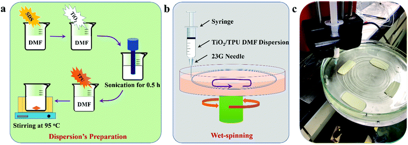
In that sense, TiO2 NPs should be exposed on the surface as much as possible during immobilization in the TPU matrix. Hollow fibers with a larger surface area were a better choice to prepare such functional composite fibers. Therefore, we prepared a novel hollow TPU-based composite fiber via a wet-spinning process by immobilizing TiO2 nanoparticles in its matrix as shown in Scheme 1.42 In this system, we used flexible and durable TPU to introduce superior stretchability, and TiO2, which acts as a functional filler for photocatalysis. First, we investigated the effect of TiO2 content on the structure and mechanical performance of the composite fibers. Then, the TiO2/TPU hollow composite fiber was woven into a textile to evaluate its photocatalytic performance. To assess the quality of the TiO2/TPU fiber, its tensile properties were investigated. Moreover, the fiber was braided into a textile to evaluate its photocatalytic performances (including degradation and hydrogen production) and stability.
Results and discussions
The surface morphologies of the as-prepared composite and neat TPU fibers were investigated using scanning electron microscopy (SEM). As shown in Fig. 1a1–2, the 1![[thin space (1/6-em)]](https://www.rsc.org/images/entities/char_2009.gif) :
:![[thin space (1/6-em)]](https://www.rsc.org/images/entities/char_2009.gif) 2 TiO2/TPU fiber with diameters of 150–240 μm presents a rough surface, indicating that a much higher catalyst content does not benefit the formation of uniform fibers in our experiments. At high concentrations, the agglomeration of TiO2 NPs by the strong van der Waals force results in the formation of dense networks in the TPU matrix. Fig. 1b1–f2 shows SEM images of 1
2 TiO2/TPU fiber with diameters of 150–240 μm presents a rough surface, indicating that a much higher catalyst content does not benefit the formation of uniform fibers in our experiments. At high concentrations, the agglomeration of TiO2 NPs by the strong van der Waals force results in the formation of dense networks in the TPU matrix. Fig. 1b1–f2 shows SEM images of 1![[thin space (1/6-em)]](https://www.rsc.org/images/entities/char_2009.gif) :
:![[thin space (1/6-em)]](https://www.rsc.org/images/entities/char_2009.gif) 5, 1
5, 1![[thin space (1/6-em)]](https://www.rsc.org/images/entities/char_2009.gif) :
:![[thin space (1/6-em)]](https://www.rsc.org/images/entities/char_2009.gif) 8, 1
8, 1![[thin space (1/6-em)]](https://www.rsc.org/images/entities/char_2009.gif) :
:![[thin space (1/6-em)]](https://www.rsc.org/images/entities/char_2009.gif) 12, and 1
12, and 1![[thin space (1/6-em)]](https://www.rsc.org/images/entities/char_2009.gif) :
:![[thin space (1/6-em)]](https://www.rsc.org/images/entities/char_2009.gif) 20 TiO2/TPU fibers and neat TPU fibers. The TiO2/TPU composite fiber shows a hollow structure when the mass ratio of TiO2
20 TiO2/TPU fibers and neat TPU fibers. The TiO2/TPU composite fiber shows a hollow structure when the mass ratio of TiO2![[thin space (1/6-em)]](https://www.rsc.org/images/entities/char_2009.gif) :
:![[thin space (1/6-em)]](https://www.rsc.org/images/entities/char_2009.gif) TPU is lower than 1
TPU is lower than 1![[thin space (1/6-em)]](https://www.rsc.org/images/entities/char_2009.gif) :
:![[thin space (1/6-em)]](https://www.rsc.org/images/entities/char_2009.gif) 5. This hollow structure enables more TiO2 to be exposed on the surface of the fibers, which will be better for the photocatalytic process. The hollow porous structure is conducive to heterogeneous catalytic reactions, promoting the diffusion and transport of reactant molecules and may help to improve the photocatalytic activity. With decreasing TiO2 content, the diameters of the holes in fibers decrease due to the decreasing supporting function of TiO2. The 1
5. This hollow structure enables more TiO2 to be exposed on the surface of the fibers, which will be better for the photocatalytic process. The hollow porous structure is conducive to heterogeneous catalytic reactions, promoting the diffusion and transport of reactant molecules and may help to improve the photocatalytic activity. With decreasing TiO2 content, the diameters of the holes in fibers decrease due to the decreasing supporting function of TiO2. The 1![[thin space (1/6-em)]](https://www.rsc.org/images/entities/char_2009.gif) :
:![[thin space (1/6-em)]](https://www.rsc.org/images/entities/char_2009.gif) 20 TiO2/TPU and neat TPU fibers (Fig. 1f1–2) exhibited a porous microstructure with folds on their surface. The fibers were elliptical, which was related to the lower support from TiO2 during TPU coagulation. A possible explanation for the formation of hollow fiber might be as follows: once the TiO2/TPU spinning suspension is extruded into the coagulation solution, acetone diffuses into the fiber.28 Simultaneously, the DMF in the fiber diffuses into the coagulation solution, and the surfactant dissolves as well. The fibers begin shrinking from the surface. The TiO2 content influences the phase diffusion and coagulation rate, and it also determines the size and percentage of pores. At a high concentration of TiO2, the agglomeration of TiO2 NPs prevents the formation of large pores.43–45 When the concentration decreases, TiO2 NPs cannot prevent the formation of large pores, so hollow pores will appear during coagulation from the surface to the interior. Interestingly, the 1
20 TiO2/TPU and neat TPU fibers (Fig. 1f1–2) exhibited a porous microstructure with folds on their surface. The fibers were elliptical, which was related to the lower support from TiO2 during TPU coagulation. A possible explanation for the formation of hollow fiber might be as follows: once the TiO2/TPU spinning suspension is extruded into the coagulation solution, acetone diffuses into the fiber.28 Simultaneously, the DMF in the fiber diffuses into the coagulation solution, and the surfactant dissolves as well. The fibers begin shrinking from the surface. The TiO2 content influences the phase diffusion and coagulation rate, and it also determines the size and percentage of pores. At a high concentration of TiO2, the agglomeration of TiO2 NPs prevents the formation of large pores.43–45 When the concentration decreases, TiO2 NPs cannot prevent the formation of large pores, so hollow pores will appear during coagulation from the surface to the interior. Interestingly, the 1![[thin space (1/6-em)]](https://www.rsc.org/images/entities/char_2009.gif) :
:![[thin space (1/6-em)]](https://www.rsc.org/images/entities/char_2009.gif) 20 TiO2/TPU and neat TPU fibers show an oval-shaped cross-section due to the lack of TiO2 NPs. Injection through the spinneret and further elongation of fibers during the winding-up process give rise to the alignment of NPs exposed on the fiber surface. Furthermore, TPU long-chain molecules align more effectively along the spinning direction during the wet-spinning process, enabling superior stretchability for the preparation of smart textiles.46
20 TiO2/TPU and neat TPU fibers show an oval-shaped cross-section due to the lack of TiO2 NPs. Injection through the spinneret and further elongation of fibers during the winding-up process give rise to the alignment of NPs exposed on the fiber surface. Furthermore, TPU long-chain molecules align more effectively along the spinning direction during the wet-spinning process, enabling superior stretchability for the preparation of smart textiles.46
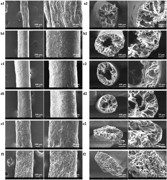 | ||
Fig. 1 (a1–e2) SEM images of as-prepared fibers which TiO2![[thin space (1/6-em)]](https://www.rsc.org/images/entities/char_2009.gif) : :![[thin space (1/6-em)]](https://www.rsc.org/images/entities/char_2009.gif) TPU was 1 TPU was 1![[thin space (1/6-em)]](https://www.rsc.org/images/entities/char_2009.gif) : :![[thin space (1/6-em)]](https://www.rsc.org/images/entities/char_2009.gif) 2, 1 2, 1![[thin space (1/6-em)]](https://www.rsc.org/images/entities/char_2009.gif) : :![[thin space (1/6-em)]](https://www.rsc.org/images/entities/char_2009.gif) 5, 1 5, 1![[thin space (1/6-em)]](https://www.rsc.org/images/entities/char_2009.gif) : :![[thin space (1/6-em)]](https://www.rsc.org/images/entities/char_2009.gif) 8, 1 8, 1![[thin space (1/6-em)]](https://www.rsc.org/images/entities/char_2009.gif) : :![[thin space (1/6-em)]](https://www.rsc.org/images/entities/char_2009.gif) 12, 1 12, 1![[thin space (1/6-em)]](https://www.rsc.org/images/entities/char_2009.gif) : :![[thin space (1/6-em)]](https://www.rsc.org/images/entities/char_2009.gif) 20, respectively; (f1 and f2) SEM images of neat TPU fiber. 20, respectively; (f1 and f2) SEM images of neat TPU fiber. | ||
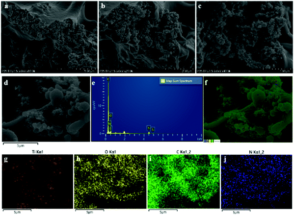
The composite fiber was also analyzed using field emission scanning electron microscopy (FE-SEM) coupled with energy-dispersive X-ray spectroscopy (EDX) to observe the dispersion of TiO2. It can be observed from the FE-SEM images of the TiO2/TPU fiber (Fig. 2a–d) that most TiO2 was exposed on the surface. The EDS spectrum and elemental mapping images (Fig. 2e–j) indicated the existence of Ti, O, C and N. Furthermore, TiO2 was not distributed inhomogeneously in the fiber, but some TiO2 aggregated. Table 1 shows the analyses of all elements, which further proved that no impurities existed in the fiber.
![[thin space (1/6-em)]](https://www.rsc.org/images/entities/char_2009.gif) :
:![[thin space (1/6-em)]](https://www.rsc.org/images/entities/char_2009.gif) 5 TiO2
5 TiO2![[thin space (1/6-em)]](https://www.rsc.org/images/entities/char_2009.gif) :
:![[thin space (1/6-em)]](https://www.rsc.org/images/entities/char_2009.gif) TPU fiber
TPU fiber
| Element | Line type | Wt% | Wt% Sigma | Atomic % |
|---|---|---|---|---|
| C | K series | 57.83 | 0.60 | 68.79 |
| N | K series | 1.28 | 0.85 | 1.31 |
| O | K series | 29.78 | 0.42 | 26.59 |
| Ti | K series | 11.12 | 0.28 | 3.32 |
| Total: | 100.00 | 100.00 |
A filament tensile test was performed to investigate the mechanical properties of the composite fibers using a TA Instruments Q800 Dynamic Mechanical Analyzer (DMA). The fiber was pasted on a small piece of paper with a 20 mm × 5 mm hole in the center, and the hole was cut open after being fixed on the DMA before measurement. It should be noted here that the 1![[thin space (1/6-em)]](https://www.rsc.org/images/entities/char_2009.gif) :
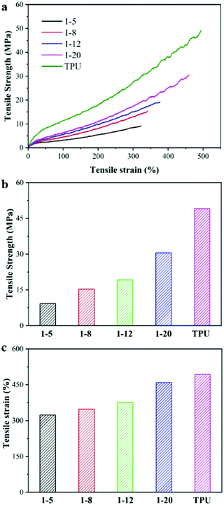
:![[thin space (1/6-em)]](https://www.rsc.org/images/entities/char_2009.gif) 2 TiO2/TPU fiber is easily broken and could not be fixed in our small piece of paper for tensile test, due to the lower tensile strength and lowest failure strain resulting from too many TiO2 inclosed in TPU matrix. The typical tensile strength–strain curves of the TiO2/TPU and neat TPU fibers are shown in Fig. 3a–c. The tensile strength of the neat TPU fiber was ∼49 MPa, with a maximum failure strain of 490%. With increasing TiO2 content, the mechanical properties of the composite fiber decreased, regardless of the tensile strength or the maximum failure strain. The fiber with a weight ratio of 1
2 TiO2/TPU fiber is easily broken and could not be fixed in our small piece of paper for tensile test, due to the lower tensile strength and lowest failure strain resulting from too many TiO2 inclosed in TPU matrix. The typical tensile strength–strain curves of the TiO2/TPU and neat TPU fibers are shown in Fig. 3a–c. The tensile strength of the neat TPU fiber was ∼49 MPa, with a maximum failure strain of 490%. With increasing TiO2 content, the mechanical properties of the composite fiber decreased, regardless of the tensile strength or the maximum failure strain. The fiber with a weight ratio of 1![[thin space (1/6-em)]](https://www.rsc.org/images/entities/char_2009.gif) :
:![[thin space (1/6-em)]](https://www.rsc.org/images/entities/char_2009.gif) 5 had the lowest tensile strength and minimum failure strain among all the composite fibers, which were ∼9 MPa and ∼322%, respectively. The decreased elongation at break in the composite fiber was attributed to the relatively poor interfacial contact with TPU and agglomeration of TiO2, which affected the stretchability of the TPU matrix.28 It should be noted that the composite fiber with higher filler content(higher than 1
5 had the lowest tensile strength and minimum failure strain among all the composite fibers, which were ∼9 MPa and ∼322%, respectively. The decreased elongation at break in the composite fiber was attributed to the relatively poor interfacial contact with TPU and agglomeration of TiO2, which affected the stretchability of the TPU matrix.28 It should be noted that the composite fiber with higher filler content(higher than 1![[thin space (1/6-em)]](https://www.rsc.org/images/entities/char_2009.gif) :
:![[thin space (1/6-em)]](https://www.rsc.org/images/entities/char_2009.gif) 5) does not present the hollow structure and easy break, so it could not be used for 20 mm filament tensile strength–strain measurement. Regardless, the 1
5) does not present the hollow structure and easy break, so it could not be used for 20 mm filament tensile strength–strain measurement. Regardless, the 1![[thin space (1/6-em)]](https://www.rsc.org/images/entities/char_2009.gif) :
:![[thin space (1/6-em)]](https://www.rsc.org/images/entities/char_2009.gif) 5 TiO2/TPU fiber is better for building smart textiles for photocatalytic applications in our experiment due to its higher content of TiO2 photocatalysts.
5 TiO2/TPU fiber is better for building smart textiles for photocatalytic applications in our experiment due to its higher content of TiO2 photocatalysts.
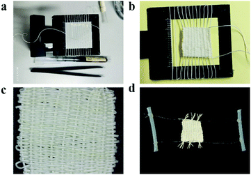
As a “green” wastewater purification technology driven by solar radiation, photocatalysis has been widely used for decomposing organic pollutants into harmless inorganic molecules. As shown in Fig. 4, the TiO2/TPU composite fiber was woven into a textile and fixed on a two-line stage to evaluate its photocatalytic performance, such as photodegradation and H2 production (more details in ESI:† Fig. S1). The photodegradation performances of the TiO2/TPU fiber-based textile were evaluated by removing RhB and 4-CP from an aqueous solution under light irradiation. The data were normalized to the same weight of the smart textile for comparison. Fig. 5a illustrates the adsorption and time-dependent photodegradation curves of 5 ppm RhB over TiO2/TPU fiber-based textiles with different TiO2 contents. More TiO2 in the fiber visibly improved the photodegradation performance. The porous hollow structures enabled more photocatalysts to be exposed on the fiber surface, which was beneficial to the contact of pollutants with photocatalysts, resulting in the excellent degradation performance of hollow fiber-based textiles. The hollow 1![[thin space (1/6-em)]](https://www.rsc.org/images/entities/char_2009.gif) :
:![[thin space (1/6-em)]](https://www.rsc.org/images/entities/char_2009.gif) 5 TiO2/TPU fiber-based textile showed the best photocatalytic performance, and the removal efficiency under light irradiation reached 99.6% after 240 min. In contrast, the 1
5 TiO2/TPU fiber-based textile showed the best photocatalytic performance, and the removal efficiency under light irradiation reached 99.6% after 240 min. In contrast, the 1![[thin space (1/6-em)]](https://www.rsc.org/images/entities/char_2009.gif) :
:![[thin space (1/6-em)]](https://www.rsc.org/images/entities/char_2009.gif) 20 TiO2/TPU fiber-based textile exhibited the worst photocatalytic performance, and the degradation efficiency decreased to 91.3% after 240 min irradiation. In addition, the effects of the initial RhB concentration on the degradation efficiency of hollow 1
20 TiO2/TPU fiber-based textile exhibited the worst photocatalytic performance, and the degradation efficiency decreased to 91.3% after 240 min irradiation. In addition, the effects of the initial RhB concentration on the degradation efficiency of hollow 1![[thin space (1/6-em)]](https://www.rsc.org/images/entities/char_2009.gif) :
:![[thin space (1/6-em)]](https://www.rsc.org/images/entities/char_2009.gif) 5 TiO2/TPU fiber-based textiles were investigated using different RhB concentrations (5, 10, 15, and 20 ppm). As shown in Fig. 5b, the degradation efficiency of RhB decreased from 99.6% to 75.6% as the initial RhB concentration increased from 5 to 20 ppm. This may be attributed to the fact that a higher concentration of RhB consumed more photogenerated reactive oxygen species. The stability of our smart textile was also vital to its practical applicability in photocatalysis. To confirm the stability of the TiO2/TPU fiber-based textile, recycling experiments were carried out on the photodegradation of RhB in five cycles. As shown in Fig. 5c, after five cycles under the same conditions, the textile still maintained a high-efficiency degradation capacity. Moreover, the device exhibited the highest degradation capacity in the third cycle, which may be due to more TiO2 exposure during the reaction. Textiles colored with RhB could also turn white in sunlight by self-cleaning as shown in Fig. S3 (ESI†), thus enabling the use of smart textiles for other applications, such as self-cleaning clothes.
5 TiO2/TPU fiber-based textiles were investigated using different RhB concentrations (5, 10, 15, and 20 ppm). As shown in Fig. 5b, the degradation efficiency of RhB decreased from 99.6% to 75.6% as the initial RhB concentration increased from 5 to 20 ppm. This may be attributed to the fact that a higher concentration of RhB consumed more photogenerated reactive oxygen species. The stability of our smart textile was also vital to its practical applicability in photocatalysis. To confirm the stability of the TiO2/TPU fiber-based textile, recycling experiments were carried out on the photodegradation of RhB in five cycles. As shown in Fig. 5c, after five cycles under the same conditions, the textile still maintained a high-efficiency degradation capacity. Moreover, the device exhibited the highest degradation capacity in the third cycle, which may be due to more TiO2 exposure during the reaction. Textiles colored with RhB could also turn white in sunlight by self-cleaning as shown in Fig. S3 (ESI†), thus enabling the use of smart textiles for other applications, such as self-cleaning clothes.
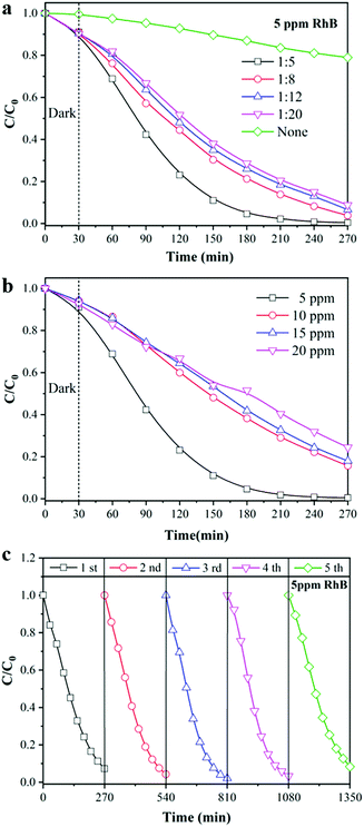 | ||
| Fig. 5 Photocatalytic degradation of RhB (a) different TiO2 content; (b) different RhB concentrations; (c) cycle experiment. | ||
In addition, the degradation efficiency of powdered TiO2 was further investigated to evaluate the performance of the fiber. Fig. 6 shows the degradation efficiency of different pollutants by powdered TiO2, in which the weight was the same as the TiO2 content of the 1![[thin space (1/6-em)]](https://www.rsc.org/images/entities/char_2009.gif) :
:![[thin space (1/6-em)]](https://www.rsc.org/images/entities/char_2009.gif) 5 TiO2/TPU fiber-based textile. Due to the sufficient contact of pollutants with the catalysts, powdered TiO2 exhibited excellent adsorption and degradation performances. TiO2/TPU fiber-based textiles could also degrade various contaminants, regardless of whether they were 5 ppm RhB, or 20 ppm RhB or 4-CP. However, there was still a large gap between the degradation ability of the fiber and powder catalyst. Hence, the challenge remained to develop more exposed surfaces of TiO2 in fiber-based textiles.
5 TiO2/TPU fiber-based textile. Due to the sufficient contact of pollutants with the catalysts, powdered TiO2 exhibited excellent adsorption and degradation performances. TiO2/TPU fiber-based textiles could also degrade various contaminants, regardless of whether they were 5 ppm RhB, or 20 ppm RhB or 4-CP. However, there was still a large gap between the degradation ability of the fiber and powder catalyst. Hence, the challenge remained to develop more exposed surfaces of TiO2 in fiber-based textiles.
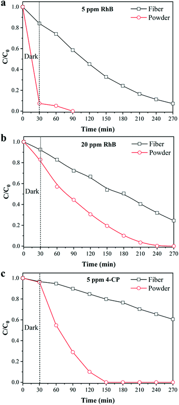 | ||
| Fig. 6 Photocatalytic degradation of RhB at different concentrations by powder TiO2: (a) 5 ppm, (b) 20 ppm; (c) photocatalytic degradation of 4-CP. | ||
Photocatalytic hydrogen production has been widely regarded as a route with good prospects for addressing the current and increasingly serious energy crisis. It is of great practical significance in the preparation of excellent and reusable photocatalytic textiles for photocatalytic H2 production as shown in Fig. S4 (ESI†). As shown in Fig. 7, the performance of the TiO2/TPU fiber-based textiles was measured by monitoring the amount of hydrogen produced from an aqueous solution containing 10 vol![[thin space (1/6-em)]](https://www.rsc.org/images/entities/char_2009.gif) % methanol as the sacrificial agent. The H2 production rates of fiber-based textiles with different TiO2 contents are displayed in Fig. 7a. The H2 production rate of the 1
% methanol as the sacrificial agent. The H2 production rates of fiber-based textiles with different TiO2 contents are displayed in Fig. 7a. The H2 production rate of the 1![[thin space (1/6-em)]](https://www.rsc.org/images/entities/char_2009.gif) :
:![[thin space (1/6-em)]](https://www.rsc.org/images/entities/char_2009.gif) 5 TiO2/TPU fiber-based textile reached 327 μmol g−1 after 4 h irradiation, which was 25 times higher than that of the 1
5 TiO2/TPU fiber-based textile reached 327 μmol g−1 after 4 h irradiation, which was 25 times higher than that of the 1![[thin space (1/6-em)]](https://www.rsc.org/images/entities/char_2009.gif) :
:![[thin space (1/6-em)]](https://www.rsc.org/images/entities/char_2009.gif) 8 TiO2/TPU fiber-based textile. The H2 production rate of the TiO2 powder catalyst was further investigated, in which the weight was the same as the TiO2 content of the 1
8 TiO2/TPU fiber-based textile. The H2 production rate of the TiO2 powder catalyst was further investigated, in which the weight was the same as the TiO2 content of the 1![[thin space (1/6-em)]](https://www.rsc.org/images/entities/char_2009.gif) :
:![[thin space (1/6-em)]](https://www.rsc.org/images/entities/char_2009.gif) 5 TiO2/TPU fiber-based textile. As displayed in Fig. 7b, the H2 production rate of the TiO2 powder catalyst reached 1984 μmol g−1 after 4 h irradiation, which was 6 times higher than that of the fiber-based textile. This was because some TiO2 was coated with TPU and even agglomerated, which reduced the reaction sites of the catalyst and significantly reduced light utilization. To investigate the stability of the 1
5 TiO2/TPU fiber-based textile. As displayed in Fig. 7b, the H2 production rate of the TiO2 powder catalyst reached 1984 μmol g−1 after 4 h irradiation, which was 6 times higher than that of the fiber-based textile. This was because some TiO2 was coated with TPU and even agglomerated, which reduced the reaction sites of the catalyst and significantly reduced light utilization. To investigate the stability of the 1![[thin space (1/6-em)]](https://www.rsc.org/images/entities/char_2009.gif) :
:![[thin space (1/6-em)]](https://www.rsc.org/images/entities/char_2009.gif) 5 TiO2/TPU fiber-based textile for H2 production, the cycle results are shown in Fig. 7c. Notably, the textile presented highly stable and excellent activity during the cycle tests. Due to greater exposure of TiO2 during the reaction, the textile performs best in photocatalytic H2 production during the third cycle, which eventually produces 346 μmol g−1. This result was consistent with the cycle results of photocatalytic degradation. By the way, our fiber-based textile shows better photocatalytic H2 production in acidic conditions as shown in Fig. S5 in the ESI.†
5 TiO2/TPU fiber-based textile for H2 production, the cycle results are shown in Fig. 7c. Notably, the textile presented highly stable and excellent activity during the cycle tests. Due to greater exposure of TiO2 during the reaction, the textile performs best in photocatalytic H2 production during the third cycle, which eventually produces 346 μmol g−1. This result was consistent with the cycle results of photocatalytic degradation. By the way, our fiber-based textile shows better photocatalytic H2 production in acidic conditions as shown in Fig. S5 in the ESI.†
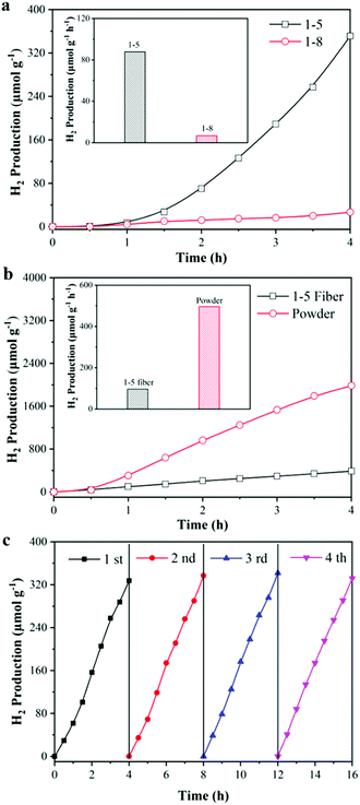 | ||
| Fig. 7 Photocatalytic H2 production activity of (a) different TiO2 content; (b) powdered TiO2 and (c) cycle experiment. | ||
From the above measurements, a possible photocatalytic mechanism for our smart textile is briefly proposed in Fig. 8. As we mentioned, TiO2 NPs are functional elements that enable the photocatalytic properties of the fiber and its textiles. Under light irradiation, excited electrons and holes are generated on TiO2 NPs on the fiber surface or inner surface, which react with RhB or water for photodegradation and hydrogen production, respectively. The more TiO2 NPs loaded on the surface or inner surface of the fiber, the higher the photocatalytic performance. Our smart textile is based on hollow composite fibers supporting TiO2 NPs on its surface as much as possible, which is why our smart textile shows such high photocatalytic performance, as shown in the right of Fig. 8. As shown in Table S1 (ESI†), our smart textile shows better photocatalytic activities than those in other literature, proving composite fiber and its textile are promising candidates to overcome separation and recovery problems of nanostructured catalysts.
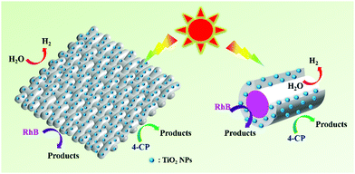 | ||
| Fig. 8 Proposed mechanism for photodegradation of RhB & 4-CP and photocatalytic H2 production over hollow composite fiber based smart textiles. | ||
Conclusions
In summary, a novel hollow composite fiber composed of TiO2 and TPU was fabricated via a simple wet-spinning method. The fiber exhibits excellent mechanical properties with high tensile strength and elongation at break. In addition, the composite fiber has excellent photocatalytic properties for degradation and hydrogen production. In particular, the 1![[thin space (1/6-em)]](https://www.rsc.org/images/entities/char_2009.gif) :
:![[thin space (1/6-em)]](https://www.rsc.org/images/entities/char_2009.gif) 5 TiO2/TPU fiber-based textile showed the best photocatalytic performance, in which the removal efficiency of 5 ppm RhB reached 99.6% and the H2 production rate was 81.75 μmol g−1 h−1. In the five-cycle test, the composite fiber showed high stability and excellent activity. The composite fiber showed the best activity in the third cycle, in terms of either degradation performance or hydrogen production performance. This may be due to greater exposure of TiO2 on the surface of the hollow fibers. Therefore, such smart textiles may open a new avenue for the practical applications of nanostructured catalysts, and we think multifunctional smart textiles will appear to solve environmental issues, such as those smart textiles that combine the removal, degradation, sensing, and detection of pollutants together during practical applications.
5 TiO2/TPU fiber-based textile showed the best photocatalytic performance, in which the removal efficiency of 5 ppm RhB reached 99.6% and the H2 production rate was 81.75 μmol g−1 h−1. In the five-cycle test, the composite fiber showed high stability and excellent activity. The composite fiber showed the best activity in the third cycle, in terms of either degradation performance or hydrogen production performance. This may be due to greater exposure of TiO2 on the surface of the hollow fibers. Therefore, such smart textiles may open a new avenue for the practical applications of nanostructured catalysts, and we think multifunctional smart textiles will appear to solve environmental issues, such as those smart textiles that combine the removal, degradation, sensing, and detection of pollutants together during practical applications.
Experimental section
Materials
Titanium dioxide nanoparticles (TiO2 NPs), acetone, N,N-dimethylformamide (DMF), thermoplastic polyurethanes (TPU), sodium dodecyl sulfate (SDS), methanol, rhodamine B (RhB), p-chlorophenol (4-CP) and chloroplatinic acid (H2PtCl6·6H2O) were all commercial analytical grade reagents and used as received without any further treatment or purification. Thermoplastic polyurethanes (TPU, Elastollan B 80 A) were obtained from BASF Co. Ltd.Wet-spinning of TiO2/TPU fibers
TiO2/TPU composite fibers were prepared via a wet-spinning process, as shown in Scheme 1. In a typical experimental procedure, 0.5 g SDS was dispersed into 15 g DMF solution under sonication for 15 min. Then, 0.125 g TiO2 was added to the mixed solution under sonication for 50 min. Thereafter, 1.0 g TPU was added and stirred at 98 °C until the solid completely dissolved. After cooling to room temperature, the TiO2/TPU suspension could be used for the wet-spinning process. The suspension was extruded from a syringe through a 23G needle into an acetone-based coagulation bath. After coagulation, the fibers were continuously collected and dried in air. In this research, the TiO2-to-TPU weight ratios of the prepared suspensions were 1![[thin space (1/6-em)]](https://www.rsc.org/images/entities/char_2009.gif) :
:![[thin space (1/6-em)]](https://www.rsc.org/images/entities/char_2009.gif) 2, 1
2, 1![[thin space (1/6-em)]](https://www.rsc.org/images/entities/char_2009.gif) :
:![[thin space (1/6-em)]](https://www.rsc.org/images/entities/char_2009.gif) 5, 1
5, 1![[thin space (1/6-em)]](https://www.rsc.org/images/entities/char_2009.gif) :
:![[thin space (1/6-em)]](https://www.rsc.org/images/entities/char_2009.gif) 8, 1
8, 1![[thin space (1/6-em)]](https://www.rsc.org/images/entities/char_2009.gif) :
:![[thin space (1/6-em)]](https://www.rsc.org/images/entities/char_2009.gif) 12 and 1
12 and 1![[thin space (1/6-em)]](https://www.rsc.org/images/entities/char_2009.gif) :
:![[thin space (1/6-em)]](https://www.rsc.org/images/entities/char_2009.gif) 20. Pure TPU fiber was also prepared as a control. To keep the TiO2 dispersed evenly, the TiO2-to-SDS weight ratio of the prepared suspensions was 1
20. Pure TPU fiber was also prepared as a control. To keep the TiO2 dispersed evenly, the TiO2-to-SDS weight ratio of the prepared suspensions was 1![[thin space (1/6-em)]](https://www.rsc.org/images/entities/char_2009.gif) :
:![[thin space (1/6-em)]](https://www.rsc.org/images/entities/char_2009.gif) 4. The fibers were woven into a textile (1.5 × 1.5 cm) as the photocatalyst for photocatalytic experiments.
4. The fibers were woven into a textile (1.5 × 1.5 cm) as the photocatalyst for photocatalytic experiments.
Characterizations
The structure of the composite fibers was investigated by using scanning electron microscopy (SEM, SNE-4500 M Plus). The distribution of elements in the fiber was investigated by using field emission scanning electron microscopy (FE-SEM, Hitachi, SU8220). Stress–strain curves of the composite fibers were obtained by using a TA Instruments Q800 dynamic mechanical analysis (DMA) device.Photodegradation performances
As a “green” wastewater purification technology driven by solar radiation, photocatalysis has been widely used for decomposing organic pollutants into harmless inorganic molecules. The TiO2/TPU composite fiber was woven into a textile and fixed on a two-line stage to evaluate its photocatalytic performance, such as photodegradation and H2 production. RhB was used as the model pollutant to evaluate the photodegradation performance of each prepared photocatalyst when illuminated by a 300 W xenon lamp. Typically, the prepared photocatalyst was added to 100 mL of RhB solution. During the photodegradation process, the concentration of RhB solution was measured by a UV-vis spectrophotometer (Jinghua, 754PC) to record the absorbance at 554 nm. The degradation percentage (η) of RhB after photoreaction for t min was then calculated by the following equation: η = (C0 − Ct)/C0 × 100% (C0 = initial RhB concentration, Ct = residual RhB concentration at t min).The degradation performance of 4-chlorophenol (4-CP) was further investigated. The prepared pollutant was a 4-CP aqueous solution (5 ppm). The process was the same as that for the photodegradation of RhB. Eventually, the concentration of the 4-CP solution was monitored with high-performance liquid chromatography (Thermo Fisher, Ultimate 3000).
Photocatalytic hydrogen evolution
The H2 generation experiment was performed in a 150![[thin space (1/6-em)]](https://www.rsc.org/images/entities/char_2009.gif) mL sealed quartz three-necked Pyrex flask, and a 300 W xenon lamp was used as the visible-light source. The photocatalyst was added to 100 mL of methanol (10 vol%, pH = 3) aqueous solution containing H2PtCl6 (Pt/TiO2 = 1 wt%). The oxygen in the reaction system was replaced with argon gas by a vacuum pump. Then, the system was irradiated under the light source. One hundred milliliter gas samples were taken at regular intervals (30 min), and the gas component was analyzed by a gas chromatograph (Fuli 9790II, with Ar as the carrier gas).
mL sealed quartz three-necked Pyrex flask, and a 300 W xenon lamp was used as the visible-light source. The photocatalyst was added to 100 mL of methanol (10 vol%, pH = 3) aqueous solution containing H2PtCl6 (Pt/TiO2 = 1 wt%). The oxygen in the reaction system was replaced with argon gas by a vacuum pump. Then, the system was irradiated under the light source. One hundred milliliter gas samples were taken at regular intervals (30 min), and the gas component was analyzed by a gas chromatograph (Fuli 9790II, with Ar as the carrier gas).
Author contributions
Jing Zhang: data curation, investigation, methodology, writing – original draft; Xuan Li and Jian Guo: methodology, validation, visualization; Gengheng Zhou, Li Xiang and Shuguang Wang: conceptualization, data curation, writing – review & editing; Zuoli He: conceptualization, supervision, project administration, funding acquisition, writing – review & editing.Conflicts of interest
There are no conflicts to declare.Acknowledgements
This research was supported under the framework of the National Natural Science Foundation of China (No. 22002071), Young Taishan Scholars Program of Shandong Province (No. tsqn. 201909026), Youth Interdisciplinary Science and Innovative Research Groups of Shandong University (Grant No. 2020QNQT014), Future Young Scholars Program of Shandong University (No. 61440089964189). The authors would like to thank Conghua Qi from Shiyanjia Lab (http://www.shiyanjia.com) for the TEM and XPS analysis. The authors thank S. Wang from The State Key Laboratory of Microbial Technology, Shandong University for his assistance with SEM.References
- L. Lin, Z. Lin, J. Zhang, X. Cai, W. Lin, Z. Yu and X. Wang, Nat. Catal., 2020, 3, 649–655 CrossRef CAS.
- J. Bian, J. Feng, Z. Zhang, Z. Li, Y. Zhang, Y. Liu, S. Ali, Y. Qu, L. Bai, J. Xie, D. Tang, X. Li, F. Bai, J. Tang and L. Jing, Angew. Chem., Int. Ed., 2019, 58, 10873–10878 CrossRef CAS PubMed.
- Z. He, C. Kim, L. Lin, T. H. Jeon, S. Lin, X. Wang and W. Choi, Nano Energy, 2017, 42, 58–68 CrossRef CAS.
- Q. Xiang, B. Cheng and J. Yu, Angew. Chem., Int. Ed., 2015, 54, 11350–11366 CrossRef CAS PubMed.
- L. Cheng, D. Zhang, Y. Liao, F. Li, H. Zhang and Q. Xiang, J. Colloid Interface Sci., 2019, 555, 94–103 CrossRef CAS PubMed.
- S. Li, C. Wang, M. Cai, F. Yang, Y. Liu, J. Chen, P. Zhang, X. Li and X. Chen, Chem. Eng. J., 2022, 428, 131158 CrossRef CAS.
- J. Wang, Y. Sun, L. Fu, Z. Sun, M. Ou, S. Zhao, Y. Chen, F. Yu and Y. Wu, Nanoscale, 2020, 12, 22030–22035 RSC.
- Z. Chen, H. Yin, C. Wang, R. Wang, Y. Peng, C. You and J. Li, Environ. Sci. Technol., 2021, 55, 9285–9292 CrossRef CAS PubMed.
- J. Mao, X. An, Z. Gu, J. Zhou, H. Liu and J. Qu, Environ. Sci. Technol., 2020, 54, 10323–10332 CrossRef CAS PubMed.
- Y. Li, D. Zhang, X. Feng, Y. Liao, Q. Wen and Q. Xiang, Nanoscale Adv., 2019, 1, 1812–1818 RSC.
- B. Osuagwu, W. Raza, A. B. Tesler and P. Schmuki, Nanoscale, 2021, 13, 12750–12756 RSC.
- A. Nicosia, F. Vento, G. M. Di Mari, L. D’Urso and P. G. Mineo, Nanomaterials, 2021, 11, 400 CrossRef CAS PubMed.
- D. H. K. Murthy, H. Matsuzaki, Q. Wang, Y. Suzuki, K. Seki, T. Hisatomi, T. Yamada, A. Kudo, K. Domen and A. Furube, Sustainable Energy Fuels, 2019, 3, 208–218 RSC.
- F. Li, L. Cheng, J. Fan and Q. Xiang, J. Mater. Chem. A, 2021, 9, 23765–23782 RSC.
- Z. He, C. Kim, T. H. Jeon and W. Choi, Appl. Catal., B, 2018, 237, 772–782 CrossRef CAS.
- A. C. Marques, M. Vale, D. Vicente, M. Schreck, E. Tervoort and M. Niederberger, Glob. Chall., 2021, 5, 202000116 Search PubMed.
- K. Ansari, S. Dalela, S. Kumar and N. Chouhan, Sustainable Energy Fuels, 2021, 5, 2545–2562 RSC.
- A. Iqbal, U. Saidu, F. Adam, S. Sreekantan, N. Yahaya, M. N. Ahmad, R. J. Ramalingam and L. D. Wilson, Molecules, 2021, 26(9), 2509 CrossRef CAS PubMed.
- C. Hua, X. Dong, N. Zheng, X. Zhang and M. Xue, Sustainable Energy Fuels, 2020, 4, 6196–6202 RSC.
- H. Wang, Z. Wu, W. Zhao and B. Guan, Chemosphere, 2007, 66, 185–190 CrossRef CAS PubMed.
- M. Gar Alalm, A. Tawfik and S. Ookawara, J. Environ. Chem. Eng., 2016, 4, 1929–1937 CrossRef CAS.
- J. Zeng, C. Peng, X. Wang, R. Wang, N. Zhang and S. Xiong, J. Appl. Polym. Sci., 2019, 136 Search PubMed.
- T. Kaur, A. Sraw, R. K. Wanchoo and A. P. Toor, Sol. Energy, 2018, 162, 45–56 CrossRef CAS.
- M. N. Chong, B. Jin, C. W. K. Chow and C. Saint, Water Res., 2010, 44, 2997–3027 CrossRef CAS PubMed.
- P. M. Martins, J. M. Ribeiro, S. Teixeira, D. Y. Petrovykh, G. Cuniberti, L. Pereira and S. Lanceros-Méndez, Materials, 2019, 12, 1649 CrossRef CAS PubMed.
- I. Vassalini, J. Gjipalaj, S. Crespi, A. Gianoncelli, M. Mella, M. Ferroni and I. Alessandri, Adv. Sustainable Syst., 2020, 4, 1900112 CrossRef CAS.
- I. Vassalini, G. Ribaudo, A. Gianoncelli, M. F. Casula and I. Alessandri, Environ. Sci.: Nano, 2020, 7, 3888–3900 RSC.
- Z. He, G. Zhou, J. H. Byun, S. K. Lee, M. K. Um, B. Park, T. Kim, S. B. Lee and T. W. Chou, Nanoscale, 2019, 11, 5884–5890 RSC.
- A. S. More, T. Lebarbé, L. Maisonneuve, B. Gadenne, C. Alfos and H. Cramail, Eur. Polym. J., 2013, 49, 823–833 CrossRef CAS.
- P. A. Charpentier, K. Burgess, L. Wang, R. R. Chowdhury, A. F. Lotus and G. Moula, Nanotechnology, 2012, 23, 425606 CrossRef CAS PubMed.
- J. Kasanen, M. Suvanto and T. T. Pakkanen, Polym. Test., 2011, 30, 381–389 CrossRef CAS.
- S. Zhang, Z. He, G. Zhou, B. M. Jung, T. H. Kim, B. J. Park, J. H. Byun and T. W. Chou, Compos. Sci. Technol., 2020, 189, 108011 CrossRef CAS.
- A. Tewari, S. Gandla, S. Bohm, C. R. McNeill and D. Gupta, ACS Appl. Mater. Interfaces, 2018, 10, 5185–5195 CrossRef CAS PubMed.
- X. Wu, Y. Han, X. Zhang and C. Lu, ACS Appl. Mater. Interfaces, 2016, 8, 9936–9945 CrossRef CAS PubMed.
- J. O. Akindoyo, M. D. H. Beg, S. Ghazali, M. R. Islam, N. Jeyaratnam and A. R. Yuvaraj, RSC Adv., 2016, 6, 114453–114482 RSC.
- Y. Meng, Y. Zhao, C. Hu, H. Cheng, Y. Hu, Z. Zhang, G. Shi and L. Qu, Adv. Mater., 2013, 25, 2326–2331 CrossRef CAS PubMed.
- B. Wang, A. Thukral, Z. Xie, L. Liu, X. Zhang, W. Huang, X. Yu, C. Yu, T. J. Marks and A. Facchetti, Nat. Commun., 2020, 11, 2405 CrossRef CAS PubMed.
- X. Pu, L. Li, M. Liu, C. Jiang, C. Du, Z. Zhao, W. Hu and Z. L. Wang, Adv. Mater., 2016, 28, 98–105 CrossRef CAS PubMed.
- Z. Li, T. Huang, W. Gao, Z. Xu, D. Chang, C. Zhang and C. Gao, ACS Nano, 2017, 11, 11056–11065 CrossRef CAS PubMed.
- S. W. Finefrock, X. Zhu, Y. Sun and Y. Wu, Nanoscale, 2015, 7, 5598–5602 RSC.
- Z. Jiang, Q. Li, M. Chen, J. Li, J. Li, Y. Huang, F. Besenbacher and M. Dong, Nanoscale, 2013, 5, 6265–6269 RSC.
- S. Zhang, Z. He, G. Zhou, B. M. Jung, T. H. Kim, B. J. Park, J. H. Byun and T. W. Chou, Compos. Sci. Technol., 2020, 189 Search PubMed.
- G. Zhou, J.-H. Byun, Y. Oh, B.-M. Jung, H.-J. Cha, D.-G. Seong, M.-K. Um, S. Hyun and T.-W. Chou, ACS Appl. Mater. Interfaces, 2017, 9, 4788–4797 CrossRef CAS PubMed.
- G. Zhou, Y. Q. Wang, J. H. Byun, J. W. Yi, S. S. Yoon, H. J. Cha, J. U. Lee, Y. Oh, B. M. Jung, H. J. Moon and T. W. Chou, ACS Nano, 2015, 9, 11414–11421 CrossRef CAS PubMed.
- Z. He, J. H. Byun, G. Zhou, B. J. Park, T. H. Kim, S. B. Lee, J. W. Yi, M. K. Um and T. W. Chou, Carbon, 2019, 146, 701–708 CrossRef CAS.
- X. Xu, P. Fan, J. Ren, Y. Cheng, J. Ren, J. Zhao and R. Song, Compos. Sci. Technol., 2018, 168, 255–262 CrossRef CAS.
Footnote |
| † Electronic supplementary information (ESI) available. See DOI: 10.1039/d1ma01200b |
| This journal is © The Royal Society of Chemistry 2022 |

