DOI:
10.1039/D1MA01141C
(Paper)
Mater. Adv., 2022,
3, 3208-3217
Mesoporous silica-based abrasion resistant antireflective (AR)-cum-hydrophobic coatings on textured solar cover glasses by a spray coating technique†
Received
3rd December 2021
, Accepted 17th February 2022
First published on 18th February 2022
Abstract
The present work describes the fabrication of functionalized mesoporous silica based antireflective-cum-hydrophobic coatings on textured solar cover glasses via a spray-coating technique; the fabricated coatings exhibit good abrasion resistance. The thicknesses of the AR and hydrophobic layers have been varied in the ranges of 350–500 nm and 30–45 nm, respectively. The application of a bilayer coating on textured solar cover glass resulted in a significant enhancement of ≥4% in the average solar transmission in the wavelength range of 400–1100 nm. A hydrophobic coating with self-cleaning properties was designed on the mesoporous silica coating, and it exhibited an enhancement of the photo-current density (mA cm−2) of 4.65% under simulated solar light of 1 sun with a maximum output power enhancement of ≥4% based on I–V (ampere-volt) characterization. After 50 cycles of sandpaper (80 mesh) abrasion testing of the coated solar cover glass, its water contact angle value was reduced from 130° to 105°, and 50 h UV radiation exposure testing confirmed that there were no significant changes in the coating quality. These results indicate the good durability, abrasion resistance, and AR/hydrophobic properties of the coatings.
1. Introduction
The generation of solar power as a renewable energy source is highly important in society for a variety of applications.1–8 In the current scenario, the development of Si solar cells or photovoltaic cells that convert direct sunlight into electric energy is drawing increasing attention because it prevents environmental pollution. Solar cell modules are normally fabricated by sandwiching an Si solar cell between a back sheet and a cover glass (front sheet) and sealing them with a resin material. The cover glass of the solar cell that protects the power-generating elements contains silicon or other related materials in its interior. In order to improve the conversion efficiency of the solar cell, the cell should take in a greater amount of sunlight. Accordingly, the cover glass must have excellent transparency and low reflectivity. For this reason, the use of mesoporous silica, which has thick pore walls with excellent hardness and a low refractive index, as a coating material could enhance both the normal and diffuse transmission of light through the solar cover glass (antireflective (AR) effect) to the solar cell, resulting in an increase in photocurrent. Presently, ‘millimeter scale textured solar cover glass’ (MSTSCG), which is the third-generation solar cover glass, is capable of trapping extra light, and has the advantages of antidazzle and positive temperature effects, is being used. Still, there exists ample scope for research to further improve the light-harvesting properties of such textured solar cover glasses. The lifetime of cover glasses for solar cell applications is also an important factor in fabricating solar cell modules. As the cover glass is exposed to open air, dust particles may adhere to it, reducing its transparency and thus decreasing the conversion efficiency of the solar cell module.1–3 To maintain the conversion efficiency of the solar cell at a desirable level, the cover glass must be coated with a protective, hard and hydrophobic layer with low reflective properties. The use of mesoporous silica with a relatively ordered pore structure as a coating layer has been proven to achieve better light conversion efficiency with easy cleaning and maintenance.4–8
Various approaches have been used to apply thin coatings on ‘solar cover glasses’ (SCGs) and solar cells to increase the efficiency and durability of the coatings deposited on solar panels or modules. Silica-based AR coatings with disordered pore structures have been reported for photovoltaic cells,9–14 solar glass and ophthalmic lenses. To improve their moisture resistance or hydrophobicity, fluorosilane4–6 and hexamethyldisilazane (HMDS)9 based precursors have been used. Some of the reported coatings have been applied on solar cover glass or solar cells and cured at high temperature with a low solar photo-current.15,16 R. Ding et al.17 developed a broadband double-layer AR coating via a solvent evaporation self-assembly method using two different mesoporous films. The broadband AR coating increases the power conversation efficiency of solar cell by 1.23% for quartz, 1.31% for borosilicate glass and 1.37% for K9 glass. Attempts were made to develop AR coatings via a sol–gel route on glass and other substrates using a single- or double-layer deposition technique.17–19 Furthermore, single-, double- or multilayer AR coatings, some with hydrophobic surfaces, on glass and solar cover glass substrates using mesoporous or low-refractive-index materials to enhance transmission or the photo-current efficiency of the solar cell have also been reported.20–33 However, these coatings showed relatively low photo-current efficiency (<3%). Gundulahelsch et al.29 prepared an AR coating with self-cleaning and photo-catalytic properties on solar cover glass using a SiO2–TiO2 sol via a dip-coating technique. Vipul Jain et al. reported a silica-based nano-coating on solar glass with 3% transmission and a water contact angle range of 109–112° using a dip-coating technique.33
With these motivations, in this work, the main objective was to develop a silica-based transparent, protective, hard and hydrophobic mesoporous coating on the millimeter scale for textured solar cover glasses (MSTSCG) that would increase the transmission to >3% and consequently enhance the output photocurrent, as well as exhibit self-cleaning properties, via the spray-coating technique. To obtain a suitable AR effect using a monolayer AR coating, the refractive index (RI) of the AR coating layer should be the geometric mean value of the refractive indices of air and the substrate (nons)1/2. The optical glass of transparent components generally has a RI of 1.47–1.92. Therefore, the RI of the AR film must be in the range of 1.21–1.38. Here, the solution for the AR coating was prepared using a silica precursor in the presence of pluronic F127 as co-block polymer via a sol–gel technique. The refractive index value of the thin films was optimized by varying the concentrations of the precursors and surfactants. The coated samples were characterized using FTIR, AFM, TEM, TG and GIXRD studies, along with evaluation of the adhesion, abrasion, optical transmission, durability and I–V (ampere-volt) characteristics of the coatings.
2. Experimental details
2.1 Materials
All chemicals were used as received. Tetraethyl orthosilicate (TEOS), methyltriethoxysilane (MTES), the surfactant Pluronic F127 (EO100PO70EO100; Mol. Wt = 12![[thin space (1/6-em)]](https://www.rsc.org/images/entities/char_2009.gif) 600 g mol−1) and 1,1,1,3,3,3-hexamethyl disilazane (HMDS) were supplied by Sigma-Aldrich, while ethanol, 1-propanol, 1-butanol, N-methyl-2-pyrrolidone, and HCl (35.4%) were obtained from MERCK Specialties Pvt. Milli-Q (Millipore) water (18.2 MΩ) was used throughout the study.
600 g mol−1) and 1,1,1,3,3,3-hexamethyl disilazane (HMDS) were supplied by Sigma-Aldrich, while ethanol, 1-propanol, 1-butanol, N-methyl-2-pyrrolidone, and HCl (35.4%) were obtained from MERCK Specialties Pvt. Milli-Q (Millipore) water (18.2 MΩ) was used throughout the study.
2.2 Preparation of sol for AR coating
For the preparation of nanocomposite AR coating sol, MTES (0.0913 mol) and TEOS (0.1875 mol) were mixed with 1-butanol (0.2844 mol), followed by adding a mixed solution of HCl (0.00122 mol), water (0.202 mol), 1-butanol (0.036 mol) and N-methyl-2-pyrrolidone (0.10 mol) to the former solution. After stirring for 10–15 min at room temperature (RT) (25 ± 2 °C), the solution was then heated at ∼60 °C for 60 min followed by cooling at RT to obtain solution A. The surfactant F127 (0.0012328 mol) was mixed with ethanol (3.41 mol) under stirring for 1.5 h to obtain solution B. Solution A was added to solution B, maintaining the optimized 6.5 wt% SiO2 equivalent and 6 wt% F127 (designated as SF-6), under stirring for 60–70 min to obtain a sol suitable for AR coating. In a similar way, by varying the surfactant concentration to 3, 5, 6, 7 and 8 wt%, different sols were prepared and designated as SF-3, SF-5, SF-6, SF-7 and SF-8, respectively (Table 1).
Table 1 Variation of the RI values of the thermally cured coatings derived from base coating sols having different F127 concentrations (with 6.5 wt% of SiO2 equivalent)
| Sample name |
Concentration of F127 present in the base coating sol (wt%) |
RI value of the thermally cured coating (measured at 633 nm) |
| SF-3 |
3 |
1.355 ± 0.005 |
| SF-5 |
5 |
1.328 ± 0.005 |
| SF-6 |
6 |
1.292 ± 0.005 |
| SF-7 |
7 |
1.288 ± 0.005 |
| SF-8 |
8 |
1.269 ± 0.005 |
2.3 Preparation of sol for hydrophobic coating
For the preparation a sol suitable for use as the hydrophobic coating, a mixed solution of TEOS (1.23 mol), MTES (1.23 mol), 1-propanol (94.2 mol), water (7.9 mol), and ammonia (0.33 mol) was prepared under stirring at RT for 2 h, followed by ageing for 4 days. To this, hexamethyldisilazane (HMDS) (0.9 mol) was added for surface modification of the SiO2 generated in the above sol and aged at RT for another 3 days. The acid-based ‘Solution-A’ prepared for AR coating was added to the above solution, maintaining the molar ratio of (TEOS + MTES)![[thin space (1/6-em)]](https://www.rsc.org/images/entities/char_2009.gif) :
:![[thin space (1/6-em)]](https://www.rsc.org/images/entities/char_2009.gif) 1-propanol
1-propanol![[thin space (1/6-em)]](https://www.rsc.org/images/entities/char_2009.gif) :
:![[thin space (1/6-em)]](https://www.rsc.org/images/entities/char_2009.gif) water
water![[thin space (1/6-em)]](https://www.rsc.org/images/entities/char_2009.gif) :
:![[thin space (1/6-em)]](https://www.rsc.org/images/entities/char_2009.gif) ammonia
ammonia![[thin space (1/6-em)]](https://www.rsc.org/images/entities/char_2009.gif) :
:![[thin space (1/6-em)]](https://www.rsc.org/images/entities/char_2009.gif) HMDS as 7.64
HMDS as 7.64![[thin space (1/6-em)]](https://www.rsc.org/images/entities/char_2009.gif) :
:![[thin space (1/6-em)]](https://www.rsc.org/images/entities/char_2009.gif) 29
29![[thin space (1/6-em)]](https://www.rsc.org/images/entities/char_2009.gif) :
:![[thin space (1/6-em)]](https://www.rsc.org/images/entities/char_2009.gif) 24.47
24.47![[thin space (1/6-em)]](https://www.rsc.org/images/entities/char_2009.gif) :
:![[thin space (1/6-em)]](https://www.rsc.org/images/entities/char_2009.gif) 1
1![[thin space (1/6-em)]](https://www.rsc.org/images/entities/char_2009.gif) :
:![[thin space (1/6-em)]](https://www.rsc.org/images/entities/char_2009.gif) 2.72 to obtain a 1.5 wt% SiO2 equivalent (considering SiO2 equivalents from TEOS + MTES + HMDS) sol for the hydrophobic coating sol.
2.72 to obtain a 1.5 wt% SiO2 equivalent (considering SiO2 equivalents from TEOS + MTES + HMDS) sol for the hydrophobic coating sol.
2.4 Coating preparation
Prior to the deposition of coatings, the glass substrates were first cleaned with detergent, followed by washing with tap water and rinsing with distilled water, and then finally cleaned with ethanol. In the first step, an AR coating was prepared on the cleaned glass substrates using the AR coating sol via the spray-coating technique (USI, Ultrasonic System Inc.). The deposited coating was dried at 70–80 °C for 12 h and heat-treated at 450 °C for 1 h in an air oven (ramp rate 1.5 °C min−1). The thicknesses of the thus-obtained coatings were in the range of 350–500 nm through XY movement of the spray head twice with the optimized spray head operational parameters, i.e., flow rate 0.5 mL min−1, head speed 100 mm s−1, spray width 15 mm and air pressure 20 psi. In the second step, the hydrophobic coating was developed on the AR-coated substrate using the hydrophobic coating sol via the above technique with a single XY movement of the spray head with the following operational parameters: flow rate 0.5 mL min−1, head speed 200 mm s−1, spray width 15 mm and air pressure 20 psi. The two-layered (AR and hydrophobic) coated substrates were then dried at 60 °C for 1 h followed by heating at 180 °C for 2 h. The thicknesses of the hydrophobic coating were designed to be 30–45 nm (≤50 nm) to avoid compromising the optical properties of the two layers.
2.5 Coating characterization
A spectroscopic ellipsometer (J. A. Woollam Co., Inc., USA) was used to measure the thickness and RI of the coatings deposited on single-side-polished Si-wafers. Coatings were developed on the substrates using an automatic ultrasonic spray-coating technique (BT Prism 400, USI, USA). The attenuated total reflection Fourier transform infrared (ATR-FTIR) spectra of the dried and heat-treated coatings were recorded using a Bruker ECO (ALPHA) spectrometer in the range of 600–4000 cm−1 with a resolution of 4 cm−1 and 200 scans. A UV/visible/NIR spectrometer (PerkinElmer Lambda 900) was used to measure the transmission spectra of the coatings. An X-ray diffractometer (Rigaku SmartLab) operating at 9 kW (200 mA, 45 kV) using Cu-Kα (λ = 1.54059 Å) radiation was used for low-angle XRD of the coatings; a grazing angle of 0.3° was maintained with a scanning speed of 1° min−1 using a step size of 0.02°. Thermogravimetric (TG) measurements were performed using a Netzsch STA model 449F3 thermal analyzer at a dynamic heating rate of 1.5 °C min−1. Transmission electron microscopy (TEM) measurements were carried out using a JEOL 2010 transmission electron microscope equipped with an EDX (energy dispersive X-ray scattering) facility. TEM samples were prepared by scraping the film and placing the scraped films on a carbon-coated copper grid. The atomic force microscopy (AFM, Nanosurf Easy scan 2, Switzerland) study (contact mode) of the AR with the hydrophobic coated glass was performed using a Nanonics instrument. Photocurrent measurement was conducted using a Keithley instrument (4200 SCS) with an attached solar simulator (model SS50AAA-EM, Photo Emission Tech., Inc., Camarillo, California). Various characterization techniques, including the cross-cut and adhesive tape test (ASTM D 3359), abrasion test using a lens coating pencil hardness tester (ASTM D 3363), thermal test, and boiling saltwater test, were carried out to evaluate/measure the mechanical strength and chemical-resistance properties of the coatings.
3. Results and discussion
3.1 Preparation of sol
Various nanocomposite sols for the AR coating were prepared with SiO2 equivalent contents of 6.5 wt% and surfactant concentrations ranging from 3–8 wt%. However, for the preparation of the sol for the hydrophobic layer (second layer coated on the AR-coated film), 1.5 wt% SiO2 equivalents were used in the absence of any surfactant. The viscosities of the sols for the AR coating were in the range of 5–6 mPa.s. The proposed reaction pathway for the preparation of the AR and hydrophobic coatings is shown schematically in Schemes 1 and 2, respectively. In the first stage, TEOS and MTES undergo acid-catalyzed hydrolysis to form Si(OH)4 and Si(OH)3CH3, respectively (Scheme 1a). The hydrolyzed species then undergo condensation to form an MTES-modified silica sol (Scheme 1b). The non-polar group –Si–CH3 plays an important role in reducing the surface free energy of the AR coating surface. During the formation of the AR coating sol, the triblock co-polymer F127 (EO100PO70EO100) forms isotropic micelles in the presence of ethanol (Scheme 1c). The micelles interact with the polymeric silica sol through hydrogen bonding and/or the weak van der Waals force. N-Methyl-2-pyrrolidone, a dipolar aprotic solvent having the ability to dissolve a variety of materials, was used in the solution to improve the wettability of the substrate to achieve a uniform coating through the spray-coating technique. Essentially, common solvents such as 1-propanol, 1-butanol and ethanol mixtures evaporated first when the solution droplets were sprayed from a certain distance (∼60 mm) as a mist on the texture glass with repeated XY direction movements, which makes it difficult to control the specific thickness of the coating materials. The coating was then oven-dried at 80 °C to form a surfactant-modified inorganic–organic hybrid coating. Upon heat treatment at 450 °C, the self-aggregated surfactants were removed, generating a porous network in the deposited silica films of the AR coating.
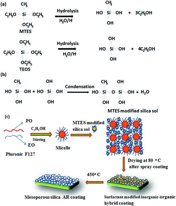 |
| | Scheme 1 The proposed reaction pathway during the preparation of the AR coating. | |
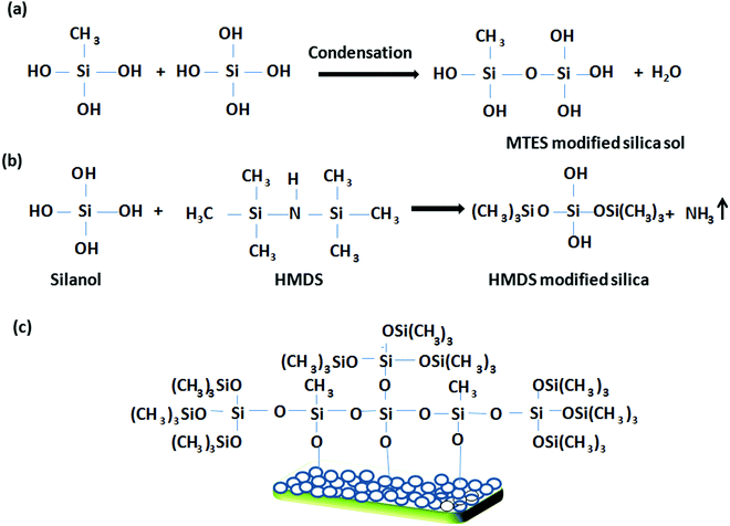 |
| | Scheme 2 A schematic representation of the tentative reaction pathway during the preparation of the hydrophobic coating. | |
Scheme 2 shows a schematic representation of the preparation of the hydrophobic coating. In this mechanistic pathway, HMDS interacts with the hydrolyzed species of TEOS to form an HMDS-modified silica sol having hydrophobic (CH3)3Si–O linkages. Finally, the MTES- and HMDS-modified silica sol interacts with the surface hydroxyl groups of the porous silica network to endow it with a harder, more hydrophobic coating via inorganic–organic hybrid moieties.34
3.2 FTIR and GIXRD
Fig. 1a presents the FTIR spectra of the as-dried (60 °C/1 h) and heat-treated (450 °C/1 h) AR coatings. The absorption bands at 2856–1961 cm−1 and 1350–1450 cm−1 are due to C–H/CH2 stretching and bending vibrations, respectively. The peak at 1276 cm−1 is attributed to Si–CH3.32 The characteristic asymmetric and symmetric stretching vibrations of Si–O–Si were indicated by the absorption bands at 1046 and 796 cm−1, respectively. However, the as-dried AR layer showed the characteristic band of Si–OH at 946 cm−1.35,36 Interestingly, the peaks originating from organic moieties (C–H/CH2) disappeared after heat treatment, indicating the complete removal of organics from SiO2, except the Si–CH3 peak (1276 cm−1), which was unaffected at this temperature.37 Thermal treatment of the coating resulted in a decrease in the Si–OH peak (946 cm−1) intensity and a shift of the Si–O–Si peak from 1046 to 1051 cm−1, indicating some silanol condensation, which helps to further strengthen the silica network.
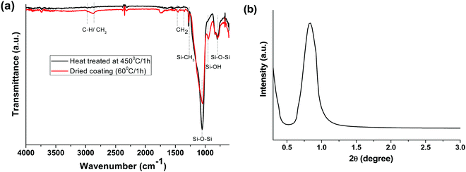 |
| | Fig. 1 (a) ATR-FTIR spectra of as-prepared and heat-treated (450 °C/1 h) AR coatings and (b) low-angle XRD patterns of the AR coated glass heated at 450 °C for 1 h. | |
A low-angle XRD study was carried out to analyse the mesostructural properties of the heat-treated AR coating at 450 °C (Fig. 1b). The broad reflection peak at around 0.7 (2 theta) indicates the porous nature of the silica layer.38,39 The mesoporous silica coating was formed via the spray coating technique due to the fast evaporation of the solvents, as well as the heat treatment of the coating.
3.3 TEM analysis
To investigate the microstructural features of the coating, a TEM study was performed (Fig. 2). Fig. 2a and b show the TEM images of the scraped SF-6 coating at different magnifications, along with the selected area diffraction (SAED) pattern (Fig. 2c) and EDX spectrum (d). Low- and high-magnification TEM images (Fig. 2a and b) confirm the mesoporous nature of the SiO2 coating with an average pore diameter of 6 nm. The volume fraction porosity (P) of the coating was evaluated using the Lorenz–Lorentz equation35 and was found to be ∼25% with a pore size of ∼6 nm. The SAED pattern (Fig. 2c) indicates the amorphous nature of the coating, while the EDX spectrum (Fig. 2d) reveals the presence of C, O and Si in the coated sample.
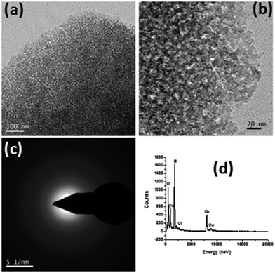 |
| | Fig. 2 (a and b) TEM images of the AR nanostructured mesoporous hydrophobic coating at different magnifications along with the (c) SAED pattern (d) and EDS spectrum. | |
3 4 AFM study
The hydrophobicity of a surface is dependent on both its chemical composition and topography. An AFM study of one representative hydrophobic film with a thickness of ∼400 nm was performed to examine the surface topography. Fig. 3 shows an AFM image of the film covering an area of 20 × 20 μm2. The surface of the AR with the hydrophobic coating was found to be spiky or micro/nano in nature with a root-mean square (rms) roughness value of about ∼64 nm. This type of surface topography favours a mesoporous-silica-based AR-cum-hydrophobic coating surface. The photovoltaic performance will completely depend on the AR-cum-hydrophobic mesoporous silica, which could improve the light trapping mechanism and reduce the surface reflection of incident light.40 The light scattering of the mesoporous hydrophobic surface is strongly related to the surface roughness, which was characterized using AFM. Therefore, it increases the diffuse transmitted light from the incident beam scattered on the rough surface with a reduction of Fresnel reflection in the polycrystalline silicon solar cell.
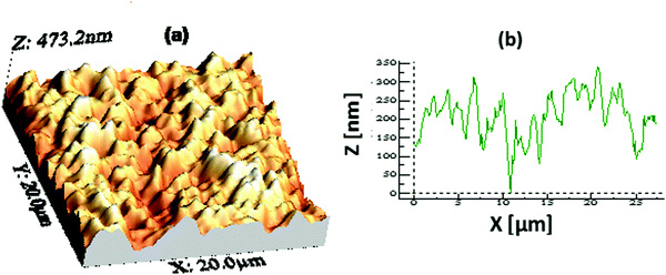 |
| | Fig. 3 (a) An AFM image (20 × 20 μm2 area) showing the surface topography of a representative coating with a thickness of ∼400 nm and (b) the peak height profile of the coating. The rms surface roughness value obtained from the image is ∼64 nm. | |
3.5 Properties of the coatings
Fig. 4 shows the spray-coating technique for the preparation of the AR with a hydrophobic layer onto a >300 × 300 mm2 solar cover glass. The optimized thickness of the coating (350 to 500 nm) shows an RI value of 1.295 ± 0.005 during the thermal decomposition of the surfactant, enhancing the porosity of the thin film. Hence, lowering the refractive index of the film, which is optically transparent and crack-free, helps to improve the optical performance of the polycrystalline silicon solar cell. The cross-cut scotch tape test (following the DIN 53151 or ASTM D 3359 specification) of the coating showed no damage, indicating good adhesion of the coated material to the substrate. The surface hardness of the AR coating was ∼5H (ASTM D 3363), and after the deposition of the hydrophobic coating on it, a hardness value of ∼3H was obtained. Table 2 shows the properties of the coatings derived from specific sols. After the application of hydrophobic coatings of thicknesses of 30–45 nm on top of the AR coating, the water contact angle (WCA) was in the range of 127 ± 3° with a hysteresis value of 10 ± 2° without affecting the AR, output power or photocurrent. The surface hydrophobicity increased due to the functionalization and micro/nanostructure of the AR coating fabricated on the millimeter-scale textured solar glass. Measuring the transmission spectra in the solar-sensitive wavelength range of 400–1100 nm on the double-layer AR-cum-hydrophobic coated SCGs for different sets of coating compositions (SF-3–SF-8), it is clear that the average solar transmission is increased ≥4% with a decrease in the reflection (average ∼4%) in SF-6 (Fig. 5 and Table 3). Lower light transmission values were observed in case of the SF-3 and SF-5 coatings compared to SF-6 due to the higher refractive index values and lower percentages of pores on the thin film surface. On the other hand, SF-7 and SF-8 coated glasses were found to show little adverse effect due to the higher percentages of surfactants present in their compositions. Fig. 5 shows the transmission spectra of the different compositions, along with that of uncoated SCGs for comparison.
 |
| | Fig. 4 Spray-coating technique for the fabrication of the AR coating with a hydrophobic layer onto >300 × 300 mm2 solar cover glass. | |
Table 2 Detailed test results for the mesoporous-silica-based AR and hydrophobic coatings on solar glass
| Name of the test/physical property |
Specifications |
Results |
| Visual appearance |
— |
Optically clear |
| Average transmission (%T) |
|
Overall %T increases about 4–5% (in the wavelength range of 400–1100 nm) as compared to bare solar glasses |
| Thickness |
— |
AR coating: 350–500 nm |
| Hydrophobic coating: 20–45 nm |
| Refractive index (RI) |
|
1.295 ± 0.005 |
| Adhesion |
DIN 53151 or ASTM D 3359 |
ASTM class 5B (highest standard) |
| Pencil hardness |
ASTM D 3363 |
≈5H; after hydrophobic coating |
| Volume fraction porosity and pore size |
— |
23–27% with a pore size of 5–7 nm |
| Water contact angle (WCA) |
— |
127 ± 3° and hysteresis of 10 ± 2° |
| Maximum photo-current density (JSC) |
— |
Increases >3 to 4.5% compared to solar panels available on the market |
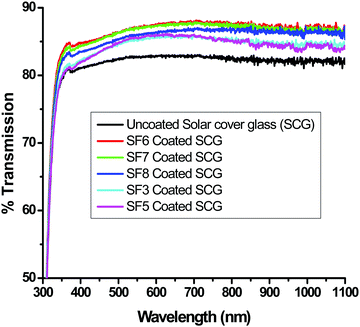 |
| | Fig. 5 Transmission spectra of bare (uncoated) solar cover glass (SCG) and those of AR-coated SCGs using different coating compositions. | |
Table 3 Percent transmission data of uncoated, AR-coated and AR-cum-hydrophobic coated millimeter-scale textured solar cover glasses (MSTSCG)
| Sample |
Average % transmission in the wavelength region |
Increase in % transmission due to AR- and AR-cum-hydrophobic coatings in comparison to the uncoated solar glass in the wavelength region |
| 400–800 nm |
800–1100 nm |
400–800 nm |
800–1100 nm |
| Millimeter-scale textured solar cover glass (SCG) (uncoated) |
82.59 |
82.15 |
— |
— |
| SCG with SF-3 AR and hydrophobic coating |
84.95 |
84.72 |
2.36 |
2.57 |
| SCG with SF-5 AR and hydrophobic coating |
85.07 |
84.38 |
2.48 |
2.23 |
| SCG with SF-6 AR and hydrophobic coating |
87.01 |
87.12 |
4.42 |
4.97 |
| SCG with SF-7 AR and hydrophobic coating |
86.82 |
86.83 |
4.23 |
4.68 |
| SCG with SF-8 AR and hydrophobic coating |
85.90 |
86.41 |
3.31 |
4.26 |
To determine their long-term durability in atmospheric conditions, the mechanical properties of the AR-cum-hydrophobic coating were evaluated via an abrasion test followed by measurement of the contact angle of the coating. For this test, 80 mesh sandpaper and a 100 g weight are required.41 First, the 80 mesh sandpaper was placed on the coated substrate and the 100 g weight was loaded on the sandpaper. The sandpaper was then pulled slowly over a distance of up to 6 cm on the coating area for 50 cycles. After 50 such cycles, the static WCA value (average data of ∼10 points) was reduced to 105° from its initial value of 130°, indicating the good abrasion-resistance properties of the coatings (Fig. 6). This indicates that the AR/hydrophobic properties remained unchanged after the abrasion test without any damage to the coating.
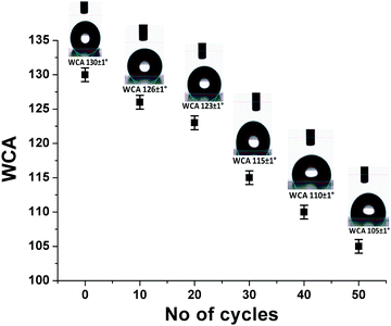 |
| | Fig. 6 Water contact angle (WCA) value (SF-6) after different numbers of abrasion cycles. | |
To determine the thermal stability of the films, the final AR sol was evaporated to dryness via heat-treatment at 80 °C for 12 h and subjected to a thermogravimetric (TG) study. The results are shown in Fig. 7. It was observed that the weight loss up to 300 °C corresponded to the liberation of moisture, trapped solvents and other volatile components present in the material. The TG curve shows an approximately 22.5% weight loss up to about 300 °C; above this temperature, the decomposition of organic components began, and beyond 450 °C, no noticeable weight loss was observed.
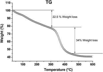 |
| | Fig. 7 TG analysis of an AR powder sample. Measurements were carried out at a heating rate of 1.5 °C min−1 in air. | |
We also evaluated the stability of the coated films with respect to UV radiation exposure (in a UV chamber) by measuring their WCA values. For this purpose, coatings of about 350 nm in thickness were prepared on solar cover glass substrates and their WCA values were measured as a function of the exposure time to UV energy radiation (intensity UV-A: 83.75 W m−2; UV-B: 13.75 W m−2, sample surface temperature: 60 °C). From the test results, it was observed that after continuous UV exposure for 50 h, the WCA of the coating changed slightly from 130° to 124°, resulting in no significant changes in the percent transmission, which indicates the good durability of the coatings.42
3.6 Solar performance
Polycrystalline solar cells were used to investigate the effect of the optimized mesoporous silica AR-cum-hydrophobic coating on the performance of the solar cell. Standard 1 sun light from a solar simulator was illuminated (illuminated area: 2 × 2 cm2) on a silicon solar cell with a coated textured solar cover glass and compared with an uncoated textured solar glass using a Keithley 4200-SCS unit to measure the electrical power through the I–V curve. From the I–V curve, it was found that maximum current density, Jsc (mA cm−2) of the SF-6 coated SCG substrate was increased up to 4.65%, and, interestingly, the maximum power output was also enhanced up to 4.0% compared to that of the uncoated solar cover glass substrate (Fig. 8 and Table 4). This also further supports the average increase of 4.66% in the light transmission value in the wavelength range of 400 to 1100 nm (Fig. 5) compared to that of the uncoated SCG. The AR performance and light-trapping efficiency were improved on the porous coated textured glass via the diffuse transmission mechanism with a reduction of the Fresnel reflection, which increases the optical path length of light to enhance the current density (Jsc) in the solar cell.
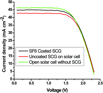 |
| | Fig. 8 Evaluation of the maximum output photo-power and short circuit current of the mesoporous-coated and uncoated textured solar cover glass. | |
Table 4 Maximum photocurrent (Imax), maximum voltage (Vmax), and maximum power (Pmax) output from a standard solar cell without cover glass, with commercial millimeter-scale textured cover glass, and with porous silica-coated commercial textured glass substrates under 1 sun for a projected illumination area of 5 × 5 cm2
| Sample |
J
sc (mA cm−2) |
V
oc (V) |
I
max (mA) |
V
max (V) |
P
max (mW) |
| Solar cell without cover glass (SCG) (1 sun on open solar cell) |
46.57 |
2.32 |
163.65 |
1.70 |
277.62 |
| Cell with SCG (uncoated) on the solar cell |
43.00 |
2.32 |
155.12 |
1.70 |
263.16 |
| Cell with SF-3 AR- and hydrophobic-coated SCG |
44.85 |
2.32 |
159.90 |
1.70 |
271.71 |
| Cell with SF-5 AR- and hydrophobic-coated SCG |
44.88 |
2.32 |
160.10 |
1.70 |
271.71 |
| Cell with SF-6 AR- and hydrophobic-coated SCG |
45.00 |
2.32 |
161.63 |
1.70 |
274.20 |
| Cell with SF-7 AR- and hydrophobic-coated SCG |
44.66 |
2.32 |
162.20 |
1.70 |
275.17 |
| Cell with SF-8 AR- and hydrophobic-coated SCG |
45.20 |
2.32 |
159.71 |
1.70 |
270.94 |
Table 4 shows the details of the I–V data of the samples coated with coatings of different compositions (SF-3, SF-5, SF-6, SF-7 and SF-8) along with the uncoated SCG and reference open solar cell. We achieved excellent I–V results through enhanced light trapping and charge carrier density using our optimized coated solar cover glass substrate as compared to the results obtained using commercially available ARC glasses on polycrystalline silicon solar cells. Therefore, the enhancement in the performance of the polycrystalline solar cells exceeded the gain in the light transmittance of the textured solar cover glass.
4. Conclusions
The present work describes the fabrication of mesoporous-silica-based transparent, hard, and antireflective (AR) coatings (thickness: 350–500 nm) with hydrophobic (WCA: 124–130°) surfaces on millimeter-scale textured solar cover glasses via a spray-coating technique. The coatings increased the photo-current density (Jsc) or power generation efficiency of solar modules and exhibited easy maintenance and/or self-cleaning properties. The bilayer-coated millimeter-scale textured solar glass showed an increase in average solar transmission of ≥4% due to the reduced reflection (average ∼4%) in the wavelength range of 400–1100 nm. The maximum output current density (JSC) of the fabricated solar cell (compared to those available on the market) increased by >3 to 4.6% (under 1 sun illumination), while the surface hydrophobicity increased after functionalization due to the micro/nanostructure of the AR coating fabricated on millimeter-scale solar glass. After 50-cycle sandpaper (80 mesh) abrasion testing, the WCA value was reduced from 130° to 105°, and the coating could withstand >50 h UV radiation exposure testing, indicating the durability and good abrasion resistance properties of the coatings. Therefore, these AR and hydrophobic coatings on solar cover glass could be useful to trap more sunlight in silicon solar cells for higher conversion efficiencies, and they would be applicable in harsh and rough environments. Therefore, this cost-effective, highly abrasion-resistant AR and hydrophobic coating could be effectively utilized to achieve superior photo-power performance in solar cells to fulfill global energy demands.
Conflicts of interest
The authors declare that they have no conflicts of interest.
Acknowledgements
The authors would like to thank the Director, CSIR-CGCRI for pursuing this work. S. Manna thanks AcSIR (CSIR) for carrying out this work. Financial support rendered by DST, Govt. of India (Sanctioned No.: IUSSTF/JCERDC-IBEE/2016-17; dated 19/01/2017) is gratefully acknowledged.
References
- H. K. Raut, A. S. Nair, S. S. Dinachali, V. A. Ganesh, T. M. Walsh and S. Ramakrishna, Sol. Energy Mater. Sol. Cells, 2013, 111, 9–15 CrossRef CAS.
- I. Das and G. De, Adv. Mater. Interfaces, 2016, 1500848–1500857 CrossRef.
- Y. N. Chanchangi, A. Ghosh, S. Sundaram and T. K. Mallick, Renewable Sustainable Energy Rev., 2020, 121, 109704–109717 CrossRef.
- S. Pendsea, K. C. S. Reddya, C. Narendraa, K. Murugana and S. Sakthivela, Sol. Energy, 2018, 163, 425–433 CrossRef.
- X. Li, J. He and W. Liu, Mater. Res. Bull., 2013, 48, 2522–2528 CrossRef CAS.
- J. Son, S. Kundu, L. K. Verma, M. Sakhuja, A. J. Danner, C. S. Bhatia and H. Yang, Sol. Energy Mater. Sol. Cells, 2012, 98, 46–51 CrossRef CAS.
- X. Li, X. Du and J. He, Langmuir, 2010, 26, 13528–13534 CrossRef CAS PubMed.
- H. Yabu and M. Shimomura, Chem. Mater., 2005, 17, 5231–5234 CrossRef CAS.
-
N. D. Kalyankar and N. Kumar, US Pat., WO2012125271 2013 Search PubMed.
- D. Bernsmeier, J. Polte, F. Ortel, T. Krahl, F. Kemnitz and R. Kraehnert, ACS Appl. Mater. Interfaces, 2014, 6(22), 19559–19565 CrossRef CAS PubMed.
- B. Reid, A. Taylor, Y. Chen, H. B. Schmidt and S. Guldin, ACS Appl. Mater. Interfaces, 2018, 10(12), 10315–10321 CrossRef CAS PubMed.
-
L. Liang, R. Blacker, N. D. Kalyankar and S. Jew Hurst, US Pat., 0272126, 2014 Search PubMed.
- D. B. Mahadik, R. V. Lakshmi and H. C. Barshilia, Sol. Energy Mater. Sol. Cells, 2015, 140, 61–68 CrossRef CAS.
-
M. Matheron, J. Biteau, J. P. Cano, J. P. Boilot and T. Gacoin, US Pat., 8182866, 2012 Search PubMed.
-
M. Zou III, C. Thompson and R. A. Fleming, US Pat, 0005886, 2016 Search PubMed.
-
S. Maghsoodi, A. Varadarajan and M. Movassat, US Pat., 0083620, 2016 Search PubMed.
- J. Wang, C. Yang, Y. Liu, C. Zhang, C. Zhang, M. Wang, J. Zhang, X. Cui, R. Ding and Y. Xu, RSC Adv., 2016, 6, 25191–25197 RSC.
- R. Xi, Y. Wang, X. Li, X. Zhang and X. Du, J. Colloid Interface Sci., 2020, 563, 42–53 CrossRef CAS PubMed.
- J. Sun, Q. Zhang, R. Ding, H. Lv, H. Yan, X. Yuan and Y. Xu, Phys. Chem. Chem. Phys., 2014, 16, 16684–16693 RSC.
- K. H. Nielsena, D. K. Orzola, S. Koynov, S. Carney, E. Hultstein and L. Wondraczek, Sol. Energy Mater. Sol. Cells, 2014, 128, 283–288 CrossRef.
- J. Wang, J. Zhang and Z. Liu, Asian J. Chem., 2013, 25(10), 5787–5789 CrossRef CAS.
- W. Zhang, J. Tu, W. Long, W. Lai, Y. Sheng and T. Guo, Energy Procedia, 2017, 130, 72–76 CrossRef CAS.
- L. Ye, S. Zhang, Q. Wang, L. Yan, H. Lv and B. Jiang, RSC Adv., 2014, 4, 35818–35822 RSC.
- C. A. Sáenz, J. A. S. García, M. Machado, M. Brizuela, O. Zubillaga and A. Tercjak, Sol. Energy Mater. Sol. Cells, 2018, 186, 154–164 CrossRef.
- N. Shanmugam, R. Pugazhendhi, R. M. Elavarasan, P. Kasiviswanathan and N. Das, Energies, 2020, 13, 2631–2723 CrossRef CAS.
- G. Womacka, K. Isbilira, F. Liscoa, G. Durandb, A. Taylorb and J. M. Wallsa, Surf. Coat. Technol., 2019, 358, 76–83 CrossRef.
- J. Hwang and H. Daiguji, Langmuir, 2013, 29(7), 2406–2411 CrossRef CAS PubMed.
- X. Du, Y. Xing, X. Li, H. Huang, Z. Geng, J. He, Y. Wen and X. Zhang, RSC Adv., 2016, 6, 7864–7871 RSC.
- G. Helsch and J. Deubener, Sol. Energy, 2012, 86(3), 831–836 CrossRef CAS.
- C. Ballif, J. Dicker, D. Borchert and T. Hofmann, Sol. Energy Mater. Sol. Cells, 2004, 82(3), 331–344 CrossRef CAS.
- X. Wang and J. Shen, J. Sol-Gel Sci. Technol., 2010, 53, 322–327 CrossRef CAS.
- S. Suthaa, S. Suresh, B. Raj and K. R. Ravia, Sol. Energy Mater. Sol. Cells, 2017, 165, 128–137 CrossRef.
- V. Jain, T. Anjilivelil, T. Sriharsha and N. Rameshbabu, J. Energy Res. Environ. Technol., 2017, 4(3), 215–220 Search PubMed.
- A. Anedda, C. M. Carbonaro, F. Clemente, R. Corpino and P. Carlo Ricci, J. Phys. Chem. B, 2003, 107, 13661–13664 CrossRef CAS.
- J. Saha, A. Mitra, A. Dandapat and G. De, Dalton Trans., 2014, 43, 5221–5229 RSC.
- J. Wang, H. Zhang, L. Wang, K. Yang, L. Cang, X. Liu and W. Huang, ACS Appl. Energy Mater., 2020, 3(5), 4484–4491 CrossRef CAS.
- X. F. Wen, K. Wang, P. H. Pi, J. X. Yang, Z. Q. Cai, L. J. Zhang, Y. Qian, Z. R. Yang, D. F. Zheng and J. Cheng, Appl. Surf. Sci., 2011, 258, 991–998 CrossRef CAS.
- Q. Meng, A. Duan, C. Xu, Z. Zhao, J. Li, B. Wang, C. Liu, D. Hu, H. Li and Y. Li, Catal. Sci. Technol., 2018, 8, 5062–5072 RSC.
- S. Abbaspour, A. A. Nourbakhsh, R. J. KalbasI and K. J. D. Mackenzie, Mol. Cryst. Liq. Cryst., 2012, 555, 104–111 CrossRef CAS.
- J. Saha and G. De, Chem. Commun., 2013, 49, 6322–6324 RSC.
- I. Das, M. K. Mishra, S. K. Medda and G. De, RSC Adv., 2014, 4, 54989–54997 RSC.
- D. A. Schaeffer, G. Polizos, D. Barton Smith, D. F. Lee, S. R. Hunter and P. G. Datskos, Nanotechnology, 2015, 26, 055602–055610 CrossRef PubMed.
Footnote |
| † Electronic supplementary information (ESI) available: Water contact angle hysteresis of coated solar cover glass. See DOI: 10.1039/d1ma01141c |
|
| This journal is © The Royal Society of Chemistry 2022 |
Click here to see how this site uses Cookies. View our privacy policy here.  Open Access Article
 a and
Samar Kumar
Medda
 *a
*a
![[thin space (1/6-em)]](https://www.rsc.org/images/entities/char_2009.gif) 600 g mol−1) and 1,1,1,3,3,3-hexamethyl disilazane (HMDS) were supplied by Sigma-Aldrich, while ethanol, 1-propanol, 1-butanol, N-methyl-2-pyrrolidone, and HCl (35.4%) were obtained from MERCK Specialties Pvt. Milli-Q (Millipore) water (18.2 MΩ) was used throughout the study.
600 g mol−1) and 1,1,1,3,3,3-hexamethyl disilazane (HMDS) were supplied by Sigma-Aldrich, while ethanol, 1-propanol, 1-butanol, N-methyl-2-pyrrolidone, and HCl (35.4%) were obtained from MERCK Specialties Pvt. Milli-Q (Millipore) water (18.2 MΩ) was used throughout the study.
![[thin space (1/6-em)]](https://www.rsc.org/images/entities/char_2009.gif) :
:![[thin space (1/6-em)]](https://www.rsc.org/images/entities/char_2009.gif) 1-propanol
1-propanol![[thin space (1/6-em)]](https://www.rsc.org/images/entities/char_2009.gif) :
:![[thin space (1/6-em)]](https://www.rsc.org/images/entities/char_2009.gif) water
water![[thin space (1/6-em)]](https://www.rsc.org/images/entities/char_2009.gif) :
:![[thin space (1/6-em)]](https://www.rsc.org/images/entities/char_2009.gif) ammonia
ammonia![[thin space (1/6-em)]](https://www.rsc.org/images/entities/char_2009.gif) :
:![[thin space (1/6-em)]](https://www.rsc.org/images/entities/char_2009.gif) HMDS as 7.64
HMDS as 7.64![[thin space (1/6-em)]](https://www.rsc.org/images/entities/char_2009.gif) :
:![[thin space (1/6-em)]](https://www.rsc.org/images/entities/char_2009.gif) 29
29![[thin space (1/6-em)]](https://www.rsc.org/images/entities/char_2009.gif) :
:![[thin space (1/6-em)]](https://www.rsc.org/images/entities/char_2009.gif) 24.47
24.47![[thin space (1/6-em)]](https://www.rsc.org/images/entities/char_2009.gif) :
:![[thin space (1/6-em)]](https://www.rsc.org/images/entities/char_2009.gif) 1
1![[thin space (1/6-em)]](https://www.rsc.org/images/entities/char_2009.gif) :
:![[thin space (1/6-em)]](https://www.rsc.org/images/entities/char_2009.gif) 2.72 to obtain a 1.5 wt% SiO2 equivalent (considering SiO2 equivalents from TEOS + MTES + HMDS) sol for the hydrophobic coating sol.
2.72 to obtain a 1.5 wt% SiO2 equivalent (considering SiO2 equivalents from TEOS + MTES + HMDS) sol for the hydrophobic coating sol.


