
 Open Access Article
 This Open Access Article is licensed under a
 Creative Commons Attribution 3.0 Unported Licence
Excellent microwave absorbing performance of biomass-derived activated carbon decorated with in situ-grown CoFe2O4 nanoparticles†
Praveen
Negi
a,
Sanjeev Kumar
Joshi
b,
Himangshu Bhusan
Baskey
c,
Sumit
Kumar
c,
Ashish Kumar
Mishra
c and
Ashavani
Kumar
 *a
*a
aDepartment of Physics, National Institute of Technology Kurukshetra, Haryana 136119, India. E-mail: ashavani@yahoo.com; ashavani@nitkkr.ac.in
bProgram office, Defence research and development organisation, 516 DRDO Bhawan, New Delhi 110011, India
cDefence Materials Stores Research and Development Establishment, (DMSRDE), Kanpur 208013, India
First published on 31st January 2022
Abstract
In this study, in situ-grown cobalt ferrite (CoFe2O4, CF) nanoparticles on waste biomass-derived porous activated carbon (AC) were grown via a facile hydrothermal technique to develop a CF/AC nanocomposite. The nanostructure and porous morphology of the nanocomposite were confirmed by FESEM, HRTEM and BET analysis. Microwave (MW) absorption analysis in the range of 2–18 GHz revealed a drastic improvement in the MW absorption performance of the CF/AC nanocomposite. Sample FAC20, having an AC loading of 20 wt%, exhibited excellent maximum reflection loss (RLmax) of −61.86 dB (@16.08 GHz) and an effective absorption bandwidth (RL < −10 dB) of 4.02 GHz at a thickness of 1.56 mm. In contrast, sample FAC30 (@30 wt% AC loading) at 1.9 mm thickness exhibited a maximum effective absorption bandwidth of 4.47 GHz in the Ku band. This remarkable MW absorption performance originates from the combination of AC and CF, which results in high impedance matching followed by sufficient attenuation of microwaves. The presence of multiple interfaces and the complicated porous structure improved the interfacial polarisation, dielectric polarisation and magnetic loss ability of the CF/AC composite. Thus, the present investigation presents the CF/AC composite as an excellent biomass-based nanocomposite for MW absorption applications.
Introduction
The swift surge in modern technology, particularly in the electronics and communication fields, has led to a large amount of electromagnetic (EM) radiation pollution, which not only impedes the proper functioning of electronic devices in civilian and military equipment but also poses a threat to human health.1,2 Thus, significant effort has been focused on the development of novel efficient microwave (MW) absorbing materials that can be used for applications such as radar absorbing materials (RAM) for aircraft to reduce their radar cross sectional area and electromagnetic interference (EMI) shielding materials to prevent signal interference.3,4A high-performance MW absorber should possess traditional properties such as strong microwave absorption and wide effective absorption bandwidth (EAB), i.e. a frequency bandwidth with a reflection loss (RL) of < −10 dB, and should be lightweight with low thickness and good thermal stability.5,6 Due to their outstanding dielectric loss properties, carbon-based materials such as graphene and carbon nanotubes (CNTs) have been widely used in MW absorbing applications. They have excellent thermal stability, light weight, and superior electrical and mechanical properties,5,7 which are essential for enhanced MW absorbers. However, their high conductivity leads to impedance mismatch, reducing their performance.8–10 Conversely, ferrites and other magnetic materials are limited by their high density, thick coating, narrow absorption bandwidth and poor impedance matching.2,8,11 Therefore, combining carbon-based materials with magnetic loss materials can reduce these problems and would result in better MW absorption properties, such as in the CoFe2O4 hollow sphere/graphene composite,12 Co-doped NiZn ferrite/graphene nanocomposite,1 Fe3O4-coated CNTs,13 Li0.3Zn0.3Co0.1Fe2.3O4@MWCNT,14 CoFe2O4/N-doped mesoporous carbon,15 CoFe2O4/rGO porous nanocomposite16 and Ni/carbon foam.17 However, these carbon-based composites have a high processing cost and are difficult to fabricate on a large scale, which limits their application.5,8
In recent years, activated carbon derived from biomass has shown potential as an efficient dielectric loss material.8,18–20 The nanopores and micropores present in biomass-based activated carbon provide a blend of solid and air; thus, the material behaves as an effective medium that can facilitate better impedance matching.18,21 Furthermore, its low density, high thermal stability, facile synthesis process and low cost make it an excellent choice for MW absorption applications.22 The combination of biomass-derived activated carbon and magnetic loss materials has resulted in a new class of MW absorbing materials. The pine nut shell-derived activated carbon/NiO nanoflake composite synthesized by Wang et al. exhibited RLmax = −33.8 dB at 6 mm thickness,23 whereas Li et al. synthesized porous activated carbon balls loaded with Fe, Co and Ni, which at 1.3 mm thickness gave an EAB of 3.4 GHz (RLmax = −50.1 dB), 3.8 GHz and 4.1 GHz, respectively.24 Similarly, for coffee waste-derived bio-carbon/MnFe2O4 composites,25 an EAB of 3.6 GHz @2.5 mm thickness and for rice husk/Fe,7 an EAB of 5.6 GHz @1.4 mm thickness were reported.
The inclusion of cobalt in AC-based composites resulted in an improvement in their MW absorption properties, e.g., the banana peel-derived porous-activated carbon/Co3O4 composite fabricated by Yusuf et al. exhibited RLmax = −51.5 dB and an EAB of 1.2 GHz at 2.5 mm thickness,26 whereas the Co/Fe2O3/activated carbon synthesized by Tahir et al. exhibited RLmax = −69.39 dB at 4 mm thickness.27 The biomass-derived carbon/NiCo2S4 synthesized by Hu et al. achieved RLmax= −62.74 dB at 2.24 mm and an excellent EAB of 7.62 GHz at 1.96 mm.5 Thus, these results suggest the potential of activated carbon/magnetic material-based composites as MW absorbing materials. Recently, we also reported the potential of waste mango leaf biomass-based activated carbon (AC) as an excellent MW absorber.20 When this AC was composited with another dielectric material, i.e., MoS2, it showed a unique dual band loss behaviour.28
Therefore, in the present study, cobalt ferrite (CF) nanoparticles were chosen as the magnetic loss material because of their high magnetic saturation value, Snoek's limit, chemical stability and mechanical hardness.7,11 Subsequently, CF nanoparticles were in situ grown on AC to form a CF/AC composite. The MW absorption study of the CF/AC composite in the frequency range of 2 to 18 GHz demonstrated that at 20 wt% loading of AC and thickness of 1.56 mm, a wide EAB of 4.02 GHz with excellent RLmax = −61.86 dB was achieved. Herein, we report the detailed study of the enhanced MW absorption performance of the CF/AC composite.
Experimental
Materials
ACS grade cobalt nitrate hexahydrate and ferric nitrate nonahydrate were purchased from Lobachemie Pvt. Ltd, AR grade potassium hydroxide (KOH) was purchased from Merck Life Science Pvt. Ltd, and 25% AR grade ammonia solution, paraffin wax and hydrochloric acid (HCl) were purchased from Lobachemie Pvt. Ltd. Ethanol was purchased from Changshu Pvt. Ltd.Synthesis of CF/AC composite
Waste mango leaves collected from the premises our institute were used as biomass, which was carbonized and activated (using KOH) to obtain activated carbon. The detailed synthesis process has been previously reported.20 The cobalt ferrite (CoFe2O4)/activated carbon composite was prepared via the hydrothermal method.29,30 Firstly, cobalt nitrate hexahydrate and ferric nitrate nonahydrate (1![[thin space (1/6-em)]](https://www.rsc.org/images/entities/char_2009.gif) :2 molar ratio) were dissolved in 30 mL deionized (DI) water and stirred for 1 h. Meanwhile, the desired amount of AC was added to 30 mL DI water and sonicated for 1 h. Thereafter, both solutions were mixed and stirred for 1 h, and then 25% ammonia solution was added to the solution until the pH of the mixture reached ∼ 9. Then 80 mL of the mixture was transferred to a Teflon-lined stainless-steel autoclave (100 mL) and kept at 180 °C for 20 h. The as-prepared precipitate was washed several times with DI water followed by ethanol under centrifugation, until the pH became neutral. The washed sample was then dried in an oven at 100 °C overnight. In all the samples, the concentration of CF was fixed, whereas the percentage loading of AC was increased, and the resulting CF/AC nanocomposites were named FAC10, FAC20 and FAC30, where the numbers 10, 20 and 30 represent the loading percentage of AC in the composite. A pure CF sample named FAC00 was also synthesized using the same procedure but without the addition of AC.
:2 molar ratio) were dissolved in 30 mL deionized (DI) water and stirred for 1 h. Meanwhile, the desired amount of AC was added to 30 mL DI water and sonicated for 1 h. Thereafter, both solutions were mixed and stirred for 1 h, and then 25% ammonia solution was added to the solution until the pH of the mixture reached ∼ 9. Then 80 mL of the mixture was transferred to a Teflon-lined stainless-steel autoclave (100 mL) and kept at 180 °C for 20 h. The as-prepared precipitate was washed several times with DI water followed by ethanol under centrifugation, until the pH became neutral. The washed sample was then dried in an oven at 100 °C overnight. In all the samples, the concentration of CF was fixed, whereas the percentage loading of AC was increased, and the resulting CF/AC nanocomposites were named FAC10, FAC20 and FAC30, where the numbers 10, 20 and 30 represent the loading percentage of AC in the composite. A pure CF sample named FAC00 was also synthesized using the same procedure but without the addition of AC.
Characterization
Powder X-ray diffraction (XRD) was performed using a Rigaku Miniflex II with Cu Kα radiation (λ = 1.54 Å). Raman spectra were recorded using a confocal micro Raman spectrometer (AIRIX CORP) with laser excitation at 532 nm. Morphology was studied via field emission scanning electron microscopy (FESEM, JEOL JSM-7610F Plus) and high-resolution transmission electron microscopy (HRTEM, JEOL JEM-F200). Magnetic measurements were performed using a SQUID-VSM magnetometer (MPMS-3). A Thermo Fisher Scientific Nexsa base was used to record X-ray photoelectron spectra (XPS). A Quantachrome Novatouch LX2 was used to measure the nitrogen adsorption–desorption isotherms at 77.3 K. The multiple-point Brunauer–Emmett–Teller (BET) method was used to calculate the specific surface area and the Barrett, Joyner, Halenda (BJH) method was used to calculate the pore size distribution.Microwave absorption measurements
To study the microwave absorption properties, the as prepared powder samples and paraffin wax were mixed and heated at 100 °C. The mixture was then pressed into a toroidal shape (φout = 7.0 mm and φin = 3.0 mm) using a die. The loading of each sample in the paraffin wax was 40 wt%. An Agilent E8364B PNA series vector network analyzer (VNA) was used to obtain the relative complex permittivity (εr) and relative complex permeability (μr) in the frequency range of 2–18 GHz. The RL values were calculated using eqn (1) and (2), as follows:7,31| RL(dB) = 20log|(Zin − Z0)/(Zin + Z0)| | (1) |
 | (2) |
Results and discussion
Morphological and structural analysis
Fig. 1a depicts the XRD patterns of the CF/AC composite with different loading wt% of AC. The diffraction peaks at 18.2°, 30.09°, 35.48°, 37.3°, 43°, 53.5°, 57°, 62.6° and 74.1° represent the Braggs reflection from the (111), (220), (311), (222), (400), (422), (511), (440) and (533) planes of the cubic spinel structure of CoFe2O4 (JCPDS Card No. 22-1086), respectively.12,32 The absence of diffraction peaks of AC in the CF/AC composite was due to the in situ growth of CF nanoparticles on the surface on AC, which resulted in low crystallinity in AC.33 The intensity of the diffraction peaks was maximum for FAC00, which can be attributed to its high level of crystallinity, but as the loading of AC increased, the diffraction peak intensity showed a decreasing trend, which is due to the amorphous nature of AC.8Fig. 1b depicts the Raman spectra of FAC10, FAC20 and FAC30, and the bands present in the Raman spectra are listed in Table 1. The peaks present between 150 cm−1 to 800 cm−1 (Fig. 1c) are assigned to the five Raman active optical modes (A1g + Eg + 3T2g) present in the cubic spinel structure Fd![[3 with combining macron]](https://www.rsc.org/images/entities/char_0033_0304.gif) m space group,34–36 showing the presence of CoFe2O4 in the CF/AC composite.29,37 The two prominent D and G bands in the Raman spectra are the characteristic feature of graphitic carbon,20 which substantiate the presence of AC in the CF/AC composite. The D band is attributed to the disorder and defects introduced in sp2 carbon.38,39 The G band arises due to the E2g vibrational mode present in aromatic carbon rings.39 The lower ID/IG ratio of FAC30 than that of FAC10 and FAC20 clearly suggests that a higher loading of AC in the CF/AC composite improves the degree of graphitization.16,39
m space group,34–36 showing the presence of CoFe2O4 in the CF/AC composite.29,37 The two prominent D and G bands in the Raman spectra are the characteristic feature of graphitic carbon,20 which substantiate the presence of AC in the CF/AC composite. The D band is attributed to the disorder and defects introduced in sp2 carbon.38,39 The G band arises due to the E2g vibrational mode present in aromatic carbon rings.39 The lower ID/IG ratio of FAC30 than that of FAC10 and FAC20 clearly suggests that a higher loading of AC in the CF/AC composite improves the degree of graphitization.16,39
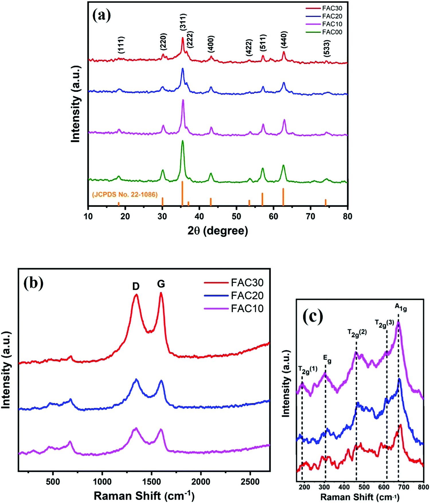 | ||
| Fig. 1 (a) XRD pattern of the samples; (b and c) Raman spectra of FAC10, FAC20 and FAC30. | ||
| Sample | Raman peak (cm−1) | Ratio of intensity | ||||||
|---|---|---|---|---|---|---|---|---|
| A1g | Eg | T2g(1) | T2g(2) | T2g(3) | D band | G band | I D/IG | |
| FAC10 | 672 | 304 | 192 | 458 | 612 | 1341 | 1592 | 1.03 |
| FAC20 | 676 | 315 | 188 | 470 | 608 | 1343 | 1598 | 1.03 |
| FAC30 | 679 | 319 | 192 | 460 | 588 | 1346 | 1595 | 0.97 |
The FESEM image in Fig. 2a depicts the successful growth of CF nanoparticles on the surface of AC. Fig. 2b reveals the presence of pores among the uniform distribution of CF nanoparticles on AC. A higher magnification, as shown in Fig. 2(c and d), clearly shows the agglomeration of CF particles into clusters, which cover some pores but simultaneously, sufficient porosity is visible. Fig. 2d shows the amalgamation of CF nanoparticles, where the porosity of AC can be seen in greater detail. Fig. 2e and Fig. S1(a) (ESI†) depict the TEM images of the bare CF nanoparticles, which show a sphere-like morphology. In contrast, the TEM images of FAC10 (Fig. S1(b), ESI†), FAC20 (Fig. 2f) and FAC30 (Fig. 2g and Fig. S1(c), ESI†) depict the uniform distribution of CF nanoparticles on AC in the CF/AC composites. The particle size distribution graph, as shown in Fig. S1(d) (ESI†), reveals that the CF nanoparticles have a size in the range of 4 to 40 nm. The plane spacing calculated from the HRTEM image of FAC20, as depicted in Fig. 2h, is 0.48 and 0.25 nm, which correspond to the (111) and (311) planes of CF, respectively. The dashed green line represents the multiple interfaces between the CF nanoparticles, which play an important role in improving the dielectric properties of the CF/AC absorber.
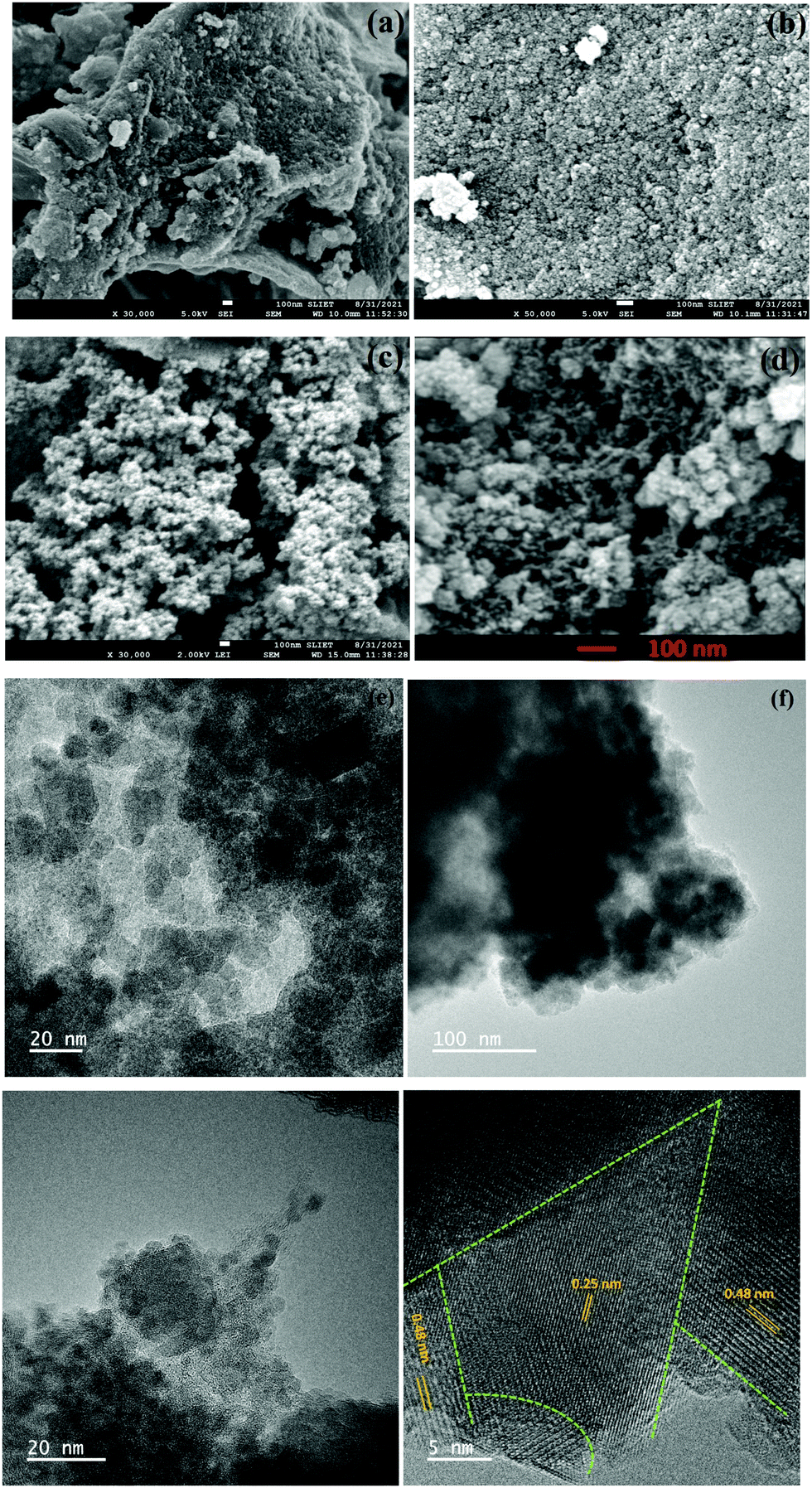 | ||
| Fig. 2 (a–d) FESEM images of FAC20, TEM images of (e) FAC00, (f) FAC20 and (g) FAC30 and (h) HRTEM image of FAC20. | ||
Further, to investigate the porosity and specific surface area of the composites, their nitrogen adsorption–desorption isotherms were measured at 77.3 K. The hysteresis curves depicted in Fig. 3(a–d) correspond to type IV isotherms for all the samples.40–42 The specific surface area and BJH pore size distribution of the samples are presented in Table 2, where it is evident that with the incorporation of AC, the surface area of the absorber increases.
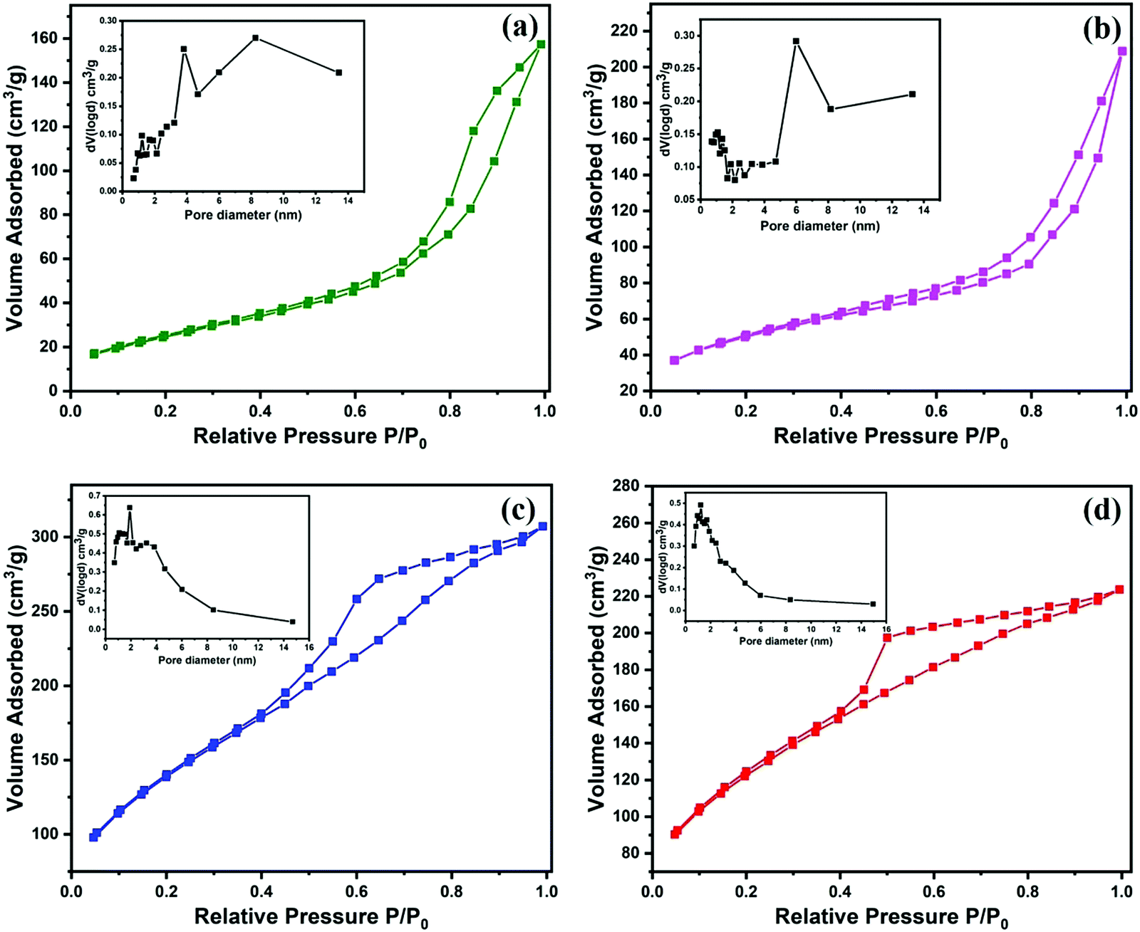 | ||
| Fig. 3 Nitrogen adsorption–desorption isotherms and pore size distribution (inset) of (a) FAC00, (b) FAC10, (c) FAC20 and (d) FAC30. | ||
| Sample | M s (emu g−1) | H c (Oe) | M r (emu g−1) | S BET (m2 g−1) | Micropore volume (cc g−1) |
|---|---|---|---|---|---|
| FAC00 | 78.48 | 493 | 14.9 | 94 | 0.253 |
| FAC10 | 68.22 | 257 | 12.2 | 176 | 0.320 |
| FAC20 | 48.68 | 106 | 3.4 | 502 | 0.481 |
| FAC30 | 38.18 | 220 | 5.8 | 435 | 0.332 |
X-Ray photoelectron spectroscopy (XPS) of sample FAC20 was performed to investigate its chemical composition and oxidation states. The full XPS spectrum of the FAC20 composite shown in Fig. 4a confirms the presence of Fe, Co, C and oxygen elements.43Fig. 4b depicts the high-resolution spectrum of Co 2p. The two main peaks present at 781.2 and 797 eV are attributed to the Co 2p3/2 and Co 2p1/2 orbitals, respectively, and satellite peaks appear at 786.8 (Co 2p3/2) and 803.6 eV (Co 2p1/2), confirming the presence of Co2+ in the FAC20 composite.44–46 The two deconvoluted peaks at 780.8 and 782.8 eV can be assigned to the Co2+ ions at the octahedral and tetrahedral sites,47,48 respectively. The Fe 2p high-resolution spectrum of Fe 2p shown in Fig. 4c contains two peaks at 711.9 and 725.4 eV, which are attributed to the Fe 2p3/2 and Fe 2p1/2 spin orbitals, respectively.46,49 The C 1s high-resolution spectrum, as shown in Fig. 4d, was de-convoluted into two peaks, where the dominant peak at 284.7 eV corresponds to the C–C/C![[double bond, length as m-dash]](https://www.rsc.org/images/entities/char_e001.gif) C group, whereas the smaller peak at 285.5 eV corresponds to the C–O group.45,49
C group, whereas the smaller peak at 285.5 eV corresponds to the C–O group.45,49
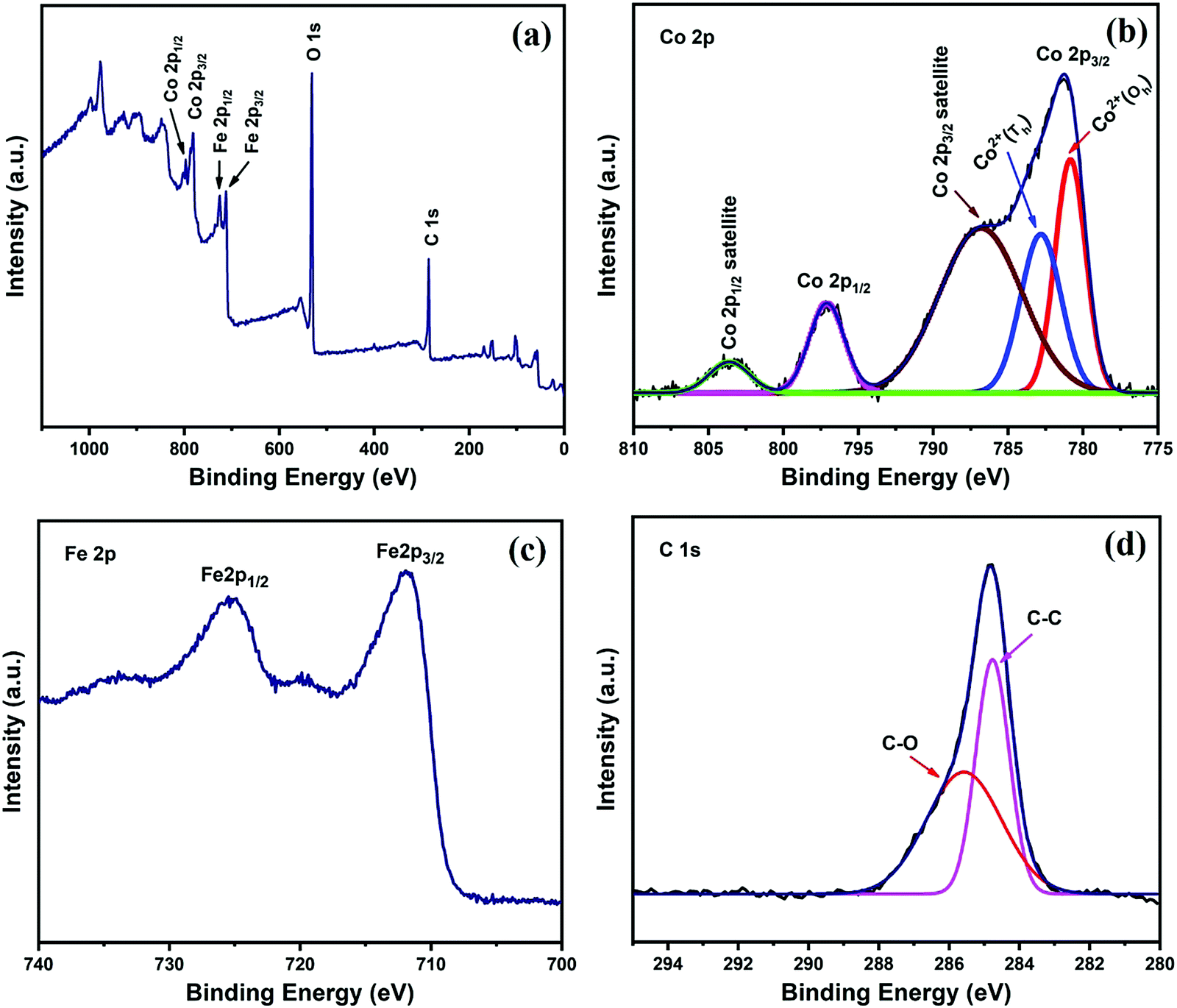 | ||
| Fig. 4 (a) XPS survey spectra and high-resolution spectra of (b) Co 2p, (c) Fe 2p and (d) C 1s for FAC20. | ||
Fig. S2 (ESI†) depicts the magnetic hysteresis loops of CF and the CF/AC composites at 300 K, which show their ferromagnetic behaviour.44,50 The saturation magnetization (Ms), coercivity (Hc) and remanent magnetization (Mr) values of all the samples are reported in Table 2. The maximum Ms value was obtained for the bare CF nanoparticles (FAC00), and thereafter showed a decreasing trend with an increase in the content of AC, which is due to the reduction of magnetic CF nanoparticles and increase in non-magnetic AC content in the CF/AC composite.51
Microwave absorption properties
ε r and μr as obtained from VNA are two important parameters to study the microwave absorption properties of an absorber. εr(εr = ε′ − iε′′) and μr(μr = μ′ − iμ′′) consist of two parts. The real part of permittivity, ε′, and real part of permeability, μ′, represent the storage of electrical and magnetic energy, respectively, whereas the imaginary part of permittivity, ε′′, and imaginary part of permeability, μ′′, represent the dissipation of electrical and magnetic energy, respectively.7,52For each sample, as depicted in Fig. 5a, the value of ε′ decreased with an increase in the frequency range, which is due to the declined response of conductance and polarization at high frequency.53 The ε′ values for the FAC00, FAC10, FAC20 and FAC30 samples are in the range of 2.8 to 2.91, 3.51 to 3.84, 9.9 to 12.09 and 7.94 to 9.69, respectively. The samples FAC10, FAC20 and FAC30 showed a higher value of ε′ compared to the bare CF (FAC00) sample because of the addition of AC, which not only increased the conduction losses but also increased the interfacial polarization due to the formation of heterogenous interfaces between the AC and CF nanoparticles.1,17,54 The value of ε′ for FAC20 is higher than that of FAC30, can be attributed to the presence of a larger number of CF nanoparticles with a 20 wt% AC loading, which not only improved the dipolar polarization but also resulted in more interfacial polarization between the CF/CF and CF/AC interfaces.54,55 Thus, FAC20 has the optimum loading of AC to provide superior dielectric storage properties. The ε′′ value, as depicted in Fig. 5b, is in the range of 0.08 to 0.15 for FAC00, 0.13 to 0.28 for FAC10, 2.03 to 3.05 for FAC20 and 1.68 to 3.02 for FAC30. Furthermore, a dielectric relaxation peak55 at 14 GHz and 16.72 GHz was observed for FAC20 and FAC30, respectively.
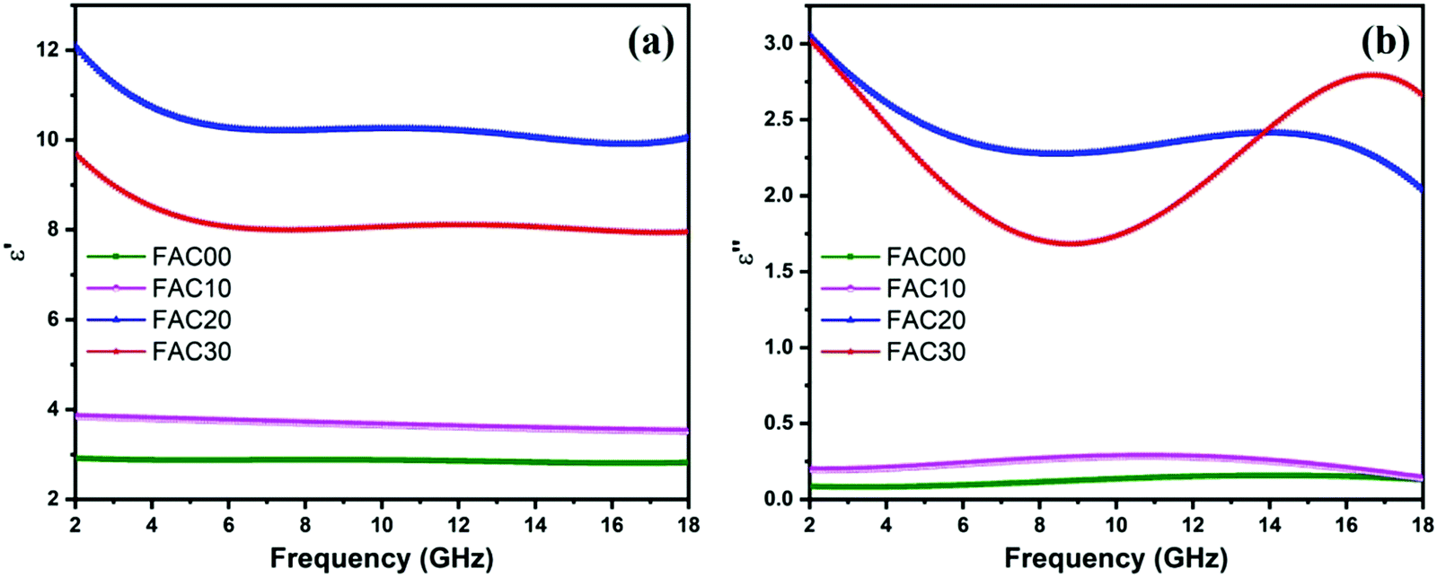 | ||
| Fig. 5 Frequency dependence of the (a) real and (b) imaginary parts of relative complex permittivity for the samples. | ||
According to the Debye theory, the imaginary permittivity can be expressed as follows:53,56
 | (3) |
According to the Debye theory, the relationship between ε′ and ε′′ can be represented as follows:38
 | (4) |
The graph of the ε′ and ε′′ curves depicts Cole–Cole semicircles, where each semicircle represents one Debye relaxation process.1,31Fig. 6(a–d) show the Cole–Cole curves of all the samples. The presence of semicircles in all the curves confirms their polarization loss abilities. However, for FAC10, FAC20 and FAC30, as depicted in Fig. 6(b–d), respectively, a measurable straight line depicting conduction loss31,38 was also observed. This increase in conduction loss can be attributed to the increase in the loading of AC, which acts as a conductive path for hopping electrons.31,53,57 Thus, due to the presence of both polarization and conduction loss, the FAC20 and FAC30 samples showed a superior dielectric loss performance among the samples (as shown in Fig. 8b).
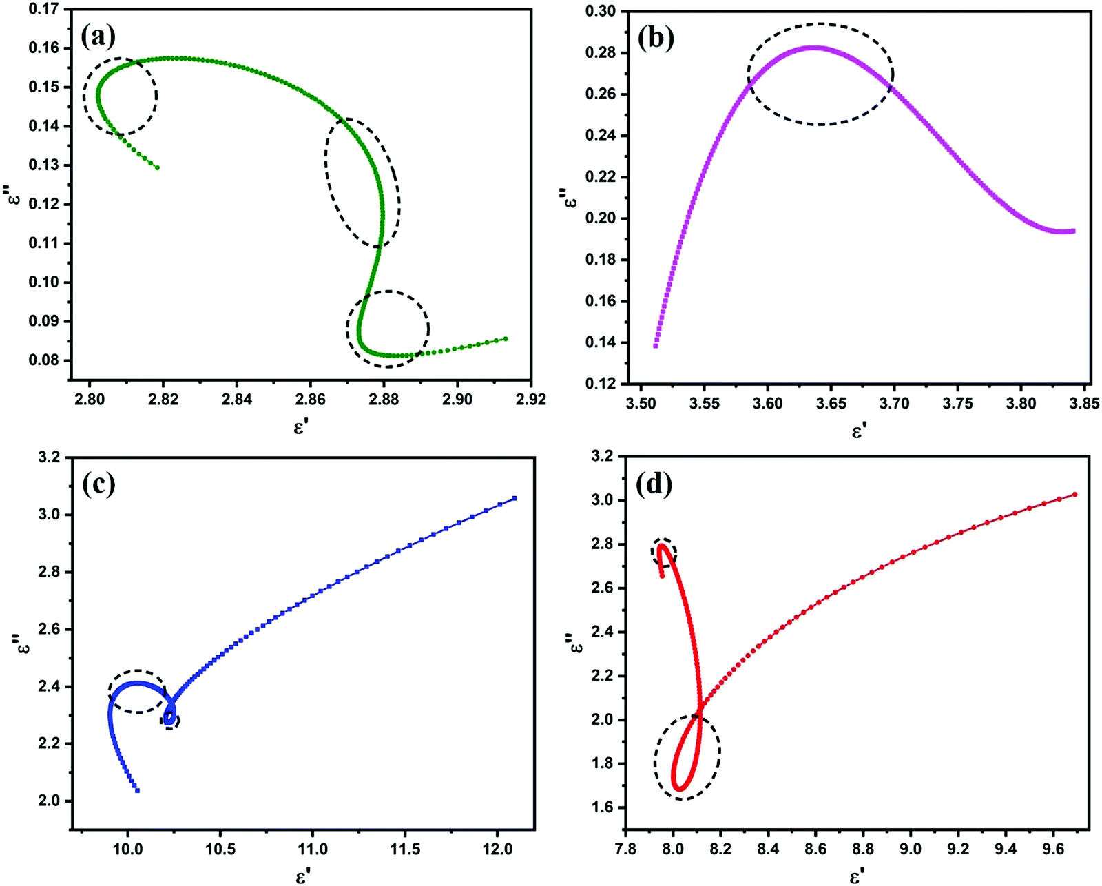 | ||
| Fig. 6 Cole–Cole plots of (a) FAC00, (b) FAC10, (c) FAC20 and (d) FAC30. | ||
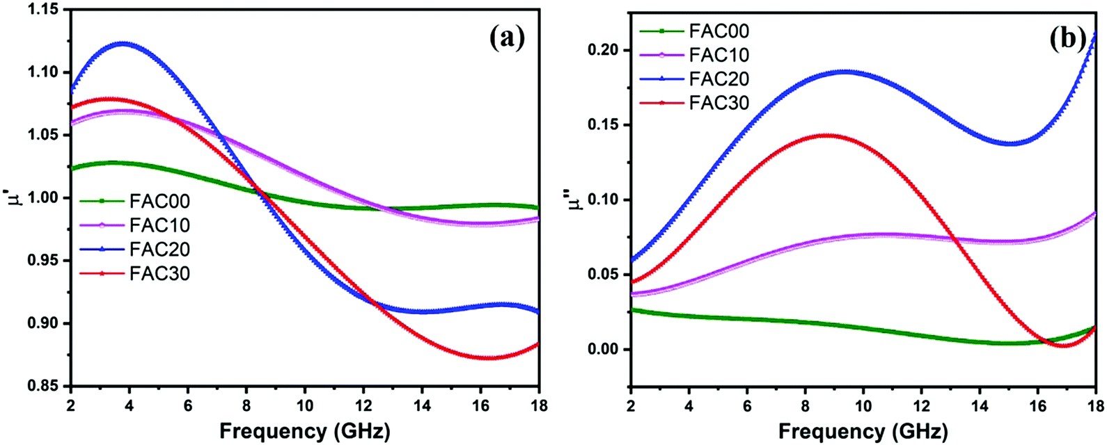
The μ′ values, as depicted in Fig. 7a, fluctuated between 0.99 to 1.02 GHz for sample FAC00, 0.97 to 1.06 GHz for FAC10, 0.90 to 1.12 GHz for FAC20 and 0.87 to 1.07 GHz for FAC30. The highest μ′ values in the frequency range of 2–7.1 GHz, 7.1–12.7 GHz and 12.7–18 GHz were obtained for FAC20, FAC10 and FAC00, respectively. As shown in Fig. 7b, the μ′′ values fluctuated between 0.003–0.026 for FAC00, 0.036–0.090 for FAC10, 0.059–0.211 for FAC20 and 0.002–0.142 for FAC30 in the frequency range of 2 to 18 GHz. The μ′′ values for FAC00 initially showed a decreasing trend from 2 to 15.28 GHz, and then increased up to 18 GHz. In contrast, FAC10 displayed a broad resonance band between 2 to 15 GHz with a minor peak located at 10.7 GHz. Similarly, FAC20 and FAC30 also showed broad resonance behaviour from 2 to 15 GHz with a peak value at 9.36 GHz and 2 to 16.9 GHz with a peak value of 8.72 GHz, respectively, which correspond to multiple magnetic resonance (MMR).58,59 The peak value of μ′′ was observed with a sharp decline in the μ′ values in the nearby frequency range, which clearly indicates that the complex permeability of the CF/AC composites has resonance characteristics,52,60,61 as shown in Fig. S3(b–d) (ESI†). Although there was no resonance peak observed for FAC00, as depicted in Fig. S3(a) (ESI†), this type of behaviour has also been reported by Liu et al.,1 where the plausible explanation is based on the relation Ha = 4|K1|/3μ0Ms and fr = γ0Ha/2π,1,58 where Ha is the anisotropic energy, K1 is the anisotropy coefficient, μ0 is the permeability in vacuum, γ0 is the gyromagnetic ratio and fr is the resonance frequency. The high Ms value of FAC00 resulted in weaker anisotropic energy, which caused the resonance frequency to be at a relatively low frequency (<2 GHz).50 This is also evident from Fig. S3(a–d) (ESI†), where only FAC00 has a larger μ′′ value at 2 GHz, and then starts decreasing with an increase in frequency, whereas for all the other samples the value of μ′′ starts increasing from 2 GHz. With the incorporation of AC in the absorber; FAC10, FAC20 and FAC30 showed a resonance peak in the frequency range of 8 to 11 GHz. The reason for this single broad resonance peak rather than multiple resonance peaks, as reported in literature,6,44,50 could be due to the particle size of CF. According to Fig. S1(d) (ESI†), the size of the CF nanoparticles for FAC10, FAC20 and FAC30 is between 4 to 40 nm, which is below the critical size limit under which the exchange resonance comes into effect.58,59,62 Thus, both natural and exchange resonance resulted in this single broad resonance peak.
 | ||
| Fig. 7 Frequency dependence of the (a) real and (b) imaginary parts of relative complex permeability for the samples. | ||
Even though activated carbon is nonmagnetic, it indirectly contributed to the enhancement in magnetic energy storage in the low frequency range of 2 to 8.4 GHz and larger magnetic energy loss in whole frequency range of 2 to 18 GHz for the CF/AC composite, except for a small range (16.32 to 17.9 GHz for FAC30, Fig. 7b). The plausible explanation for this can be related to the large surface area and pores present in AC, which resulted in the larger interaction of MW with the CF nanoparticles embedded on the surface and inside the pores in AC, where a similar type of behaviour was also reported by Wang et al.63 This is evident for FAC20, which has the maximum specific surface area and the maximum values of μ′′ in the complete frequency range. Thus, the presence of AC in the absorber makes the CF nanoparticles more effective for magnetic energy dissipation.
The general cause of magnetic loss in magnetic materials originates from their natural resonance, domain wall resonance, hysteresis, exchange resonance and eddy current losses.1,50,64 The domain wall resonance and hysteresis loss are negligible in the microwave frequency range,1,65 while the eddy current loss can be evaluated using the following equation:52
| μ′′ ≈ 2πμ0(μ′)2σd2f/3 | (5) |
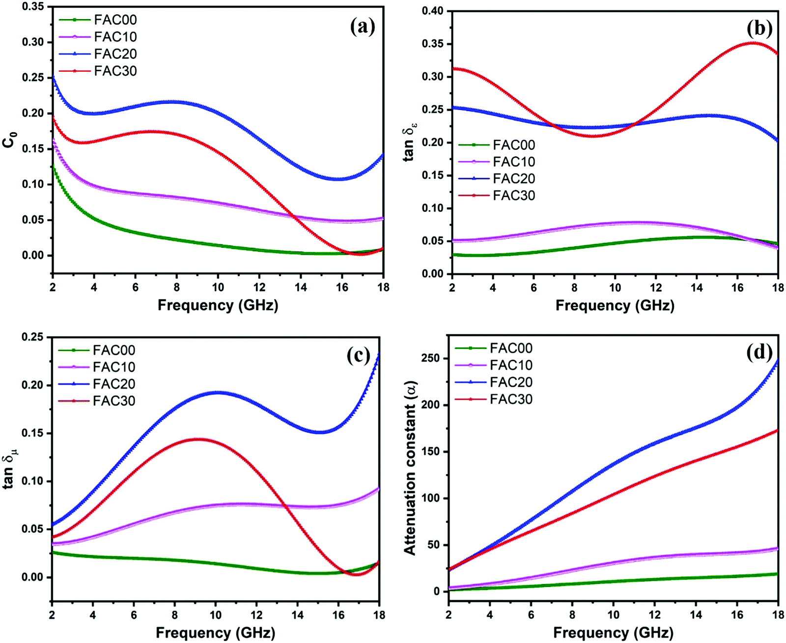 | ||
| Fig. 8 (a) Frequency dependence of Co, (b) dielectric loss tangent, (c) magnetic loss tangent and (d) attenuation constant (α) for all the samples. | ||
The dielectric loss tangent 23 (tanδε = ε′′/ε′), as depicted in Fig. 8b, clearly shows that the dielectric loss ability of the absorber increases with an increase in the AC loading. FAC30 shows superior dielectric loss ability in the frequency range of 2 to 7.04 GHz and 10.88 to 18 GHz, whereas in the remaining frequency range of 7.04 to 10.88 GHz, FAC20 showed the highest dielectric loss ability.
Fig. 8c depicts the magnetic loss tangent23 (tanδμ = μ′′/μ′), where it is evident that all the samples show the same trend that as of μ′′. The tanδμ values for FAC00 range from 0.0039 to 0.026 with minor fluctuations. In the case of FAC10, the magnetic loss dominated the dielectric loss in the higher frequency range of 13.2 to 18 GHz. FAC20 showed maximum tanδμ values in the whole frequency range of 2 to 18 GHz with a maximum value of 0.23 at 18 GHz. The MW energy loss for FAC20 was dominated by dielectric loss in the whole frequency range except from 17.68 to 18 GHz. In contrast, for FAC30, dielectric loss dominated the complete frequency range of 2 to 18 GHz, which is due to the presence of a high concentration of AC.
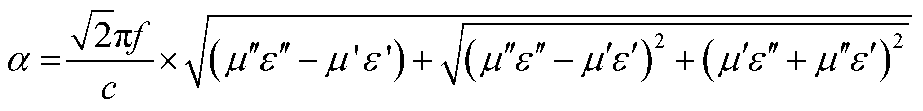
The attenuation constant38 (α) is an important tool to understand the MW absorption mechanism of an absorber. Thus, it was calculated using eqn (6) for all the samples and is shown in Fig. 8d.
 | (6) |
Although for the majority of frequency range the dielectric tangent loss value of FAC30 is greater than that of FAC20, the overall attenuation (α) ability of FAC20 is better than that of FAC30, which is because of the higher tanδμ values of FAC20 than the other samples. Thus, the synergy between both dielectric and magnetic loss resulted in enhanced MW attenuation abilities for FAC20.
Fig. S4(a–d) (ESI†) show the impedance matching (Z) curves for all the samples. The Z was calculated using the relation Z = |Zin/Z0|, where Z0 denotes the impedance of air. The closer the value of Z closer to 1, the better the impedance matching.7 High impedance matching is an important parameter for the enhancement in MW absorption performance.
The peak Z values were in the range of 12.11 to 12.70 for FAC00, 4.39 to 5.10 for FAC10, 0.96 to 1.26 for FAC20 and 1.21 to 1.34 for FAC30. The addition of AC in the absorber significantly improved its Z values. However, due to the low content of AC in FAC10, this absorber was not able to attain substantial dielectric loss ability, resulting in lower values of relative permittivity in comparison to FAC20 and FAC30, leading to its poor impedance matching performance. The incorporation of AC provides a conductive path for electrons, and according to Cao's electron hopping model,68,69 when the path of these electrons is hindered due to defects and disorder present in AC, the electrons can hop across these barriers by absorbing the EM energy, thus maintaining a conductive network across the CF/AC composite. Higher conductivity can also lead to the surface reflection of MW, which reduces the impedance matching of the absorber, as in the case of FAC30. Overall, FAC20 exhibited the maximum impedance matching characteristics, which is due to the synergy among the conductivity, dielectric loss and magnetic loss in the AC and CF nanoparticles. Thus, these results suggest that the optimal loading of AC in the CF/AC composite is 20 wt%.
Fig. 9a depicts the RL curves for sample FAC00 at various thicknesses, where this sample exhibited a poor MW absorption performance given that all the RL values were below −2 dB. When AC was introduced with a 10 wt% loading in the absorber (FAC10), as shown in Fig. 9b, the RL values improved in comparison with that of FAC00, but it also failed to qualify as an MW absorbing material given that its maximum RL value was only −4.16 dB at 4 mm thickness. The reason for the poor MW absorption performance for FAC00 is the lack of conduction loss due to the absence of AC, which led to impedance mismatch and low values of dielectric losses. In contrast, for FAC10, the loading of AC improved the Z, tanδε and α values in comparison with that of FAC00, but this was still not good enough to qualify as an MW absorber.
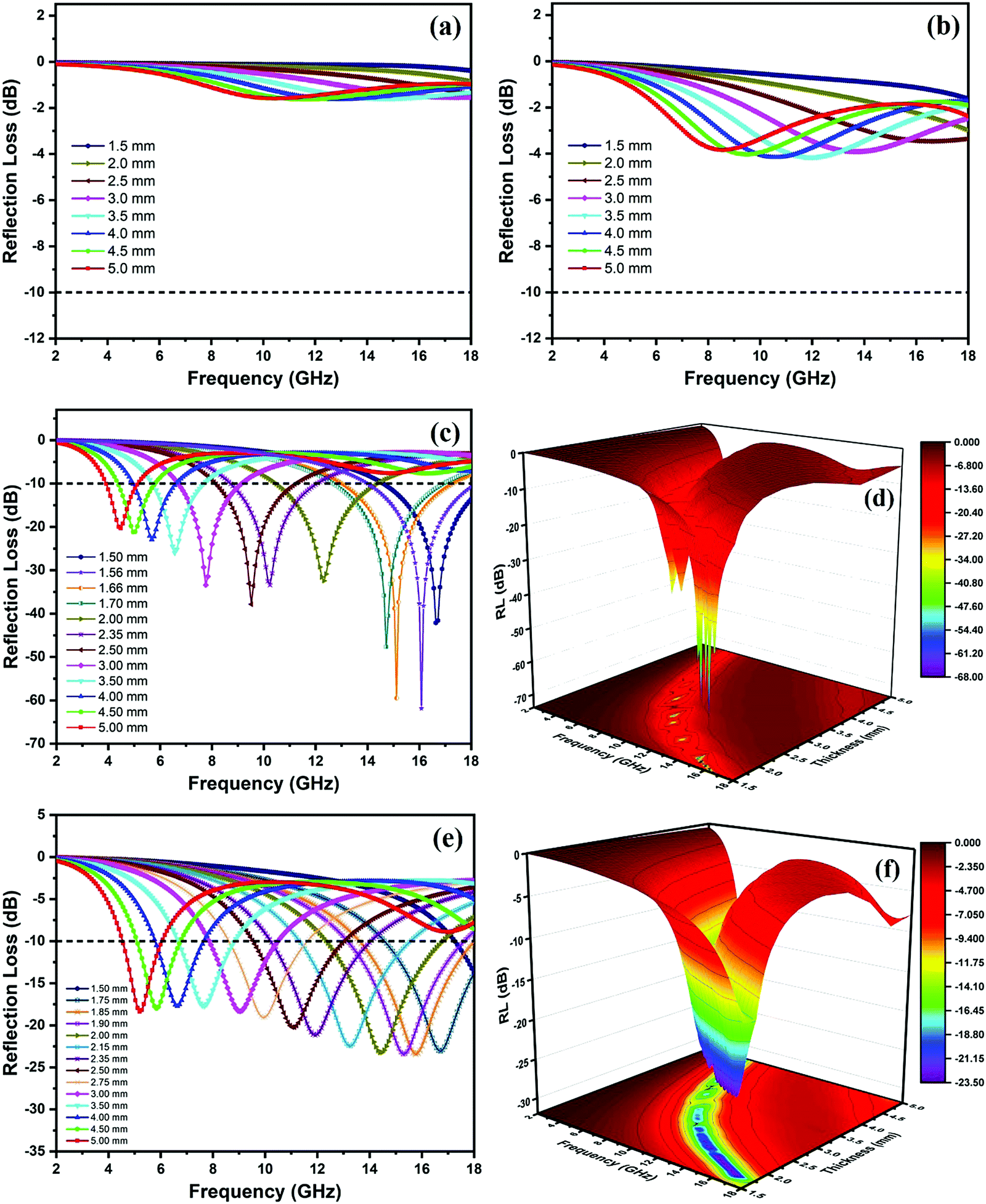 | ||
| Fig. 9 Reflection loss curves of (a) FAC00, (b) FAC10, (c) FAC20 and (e) FAC30 and 3-D graph of (d) FAC20 and (f) FAC30 at thicknesses ranging from 1.5 mm to 5 mm. | ||
With a further increase in AC loading to 20 wt% (FAC20), the microwave absorption performance of the absorber showed a notable enhancement. As shown in Fig. 9c (3D graph in Fig. 9d), FAC20 exhibited an excellent RLmax = −61.86 dB at 16.08 GHz and an EAB of 4.02 GHz (13.98 to 18 GHz) at a thickness of 1.56 mm. FAC20 also gave RLmax = −59.5 dB at 15.12 GHz and an EAB of 4.25 GHz (13.04 to 17.29 GHz) at 1.66 mm thickness, which covered 70.8% of the Ku band. An EAB of 3.3 GHz (8.73 to 12.03 GHz) covering 81.75% of the X band was also obtained by FAC20 at 2.35 mm thickness with RLmax = −33.37 (@10.24 GHz). Fig. 9(e and f) depict the RL graph and 3D graph of FAC30, respectively, which exhibited a maximum EAB of 4.47 GHz, covering 74.5% of the Ku band at 1.9 mm and 2 mm thicknesses, whereas RLmax = −23.43 dB was obtained at 15.76 GHz for 1.85 mm thickness. It is clear from the results that although the AC loading was the maximum in the FAC30 CF/AC composite, its MW absorption properties were lower compared to that of FAC20. The reason for this enhanced MW absorption performance of FAC20 can be attributed to its optimum quantity of CF and AC, which led to the maximum impedance matching and larger attenuation constant values compared to the other samples.
The impact of attenuation constant on the RL can also be realized in Fig. 10(a and b), which depict the combined graph of RL, α and impedance matching of FAC20 and FAC30 at 1.56 mm and 1.85 mm thickness, respectively. Points a and b show identical Z values, as depicted in both the graphs, but the maximum RL was attained at point a. This is because of the larger value of α at point a.
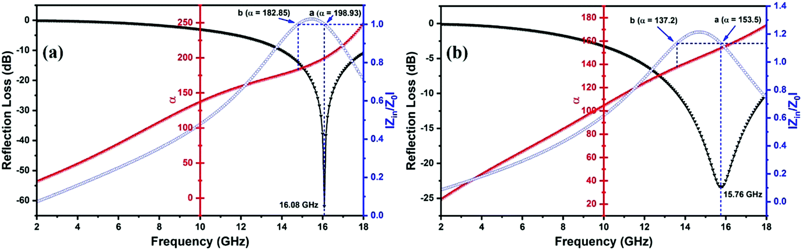 | ||
| Fig. 10 Frequency dependence of RL, α and Z values for (a) FAC20 and (b) FAC30. | ||
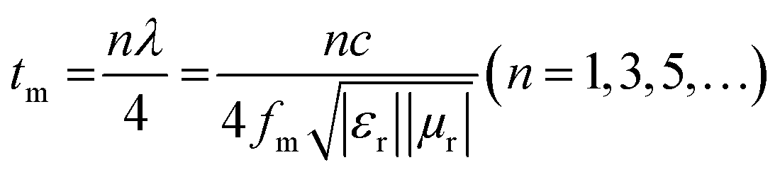
The thickness of an absorber is also an important tool for manipulating its MW-absorbing performance. According to the quarter wavelength matching model, the relation between thickness (tm) and peak frequency (fm) can be expressed as follows:44
 | (7) |
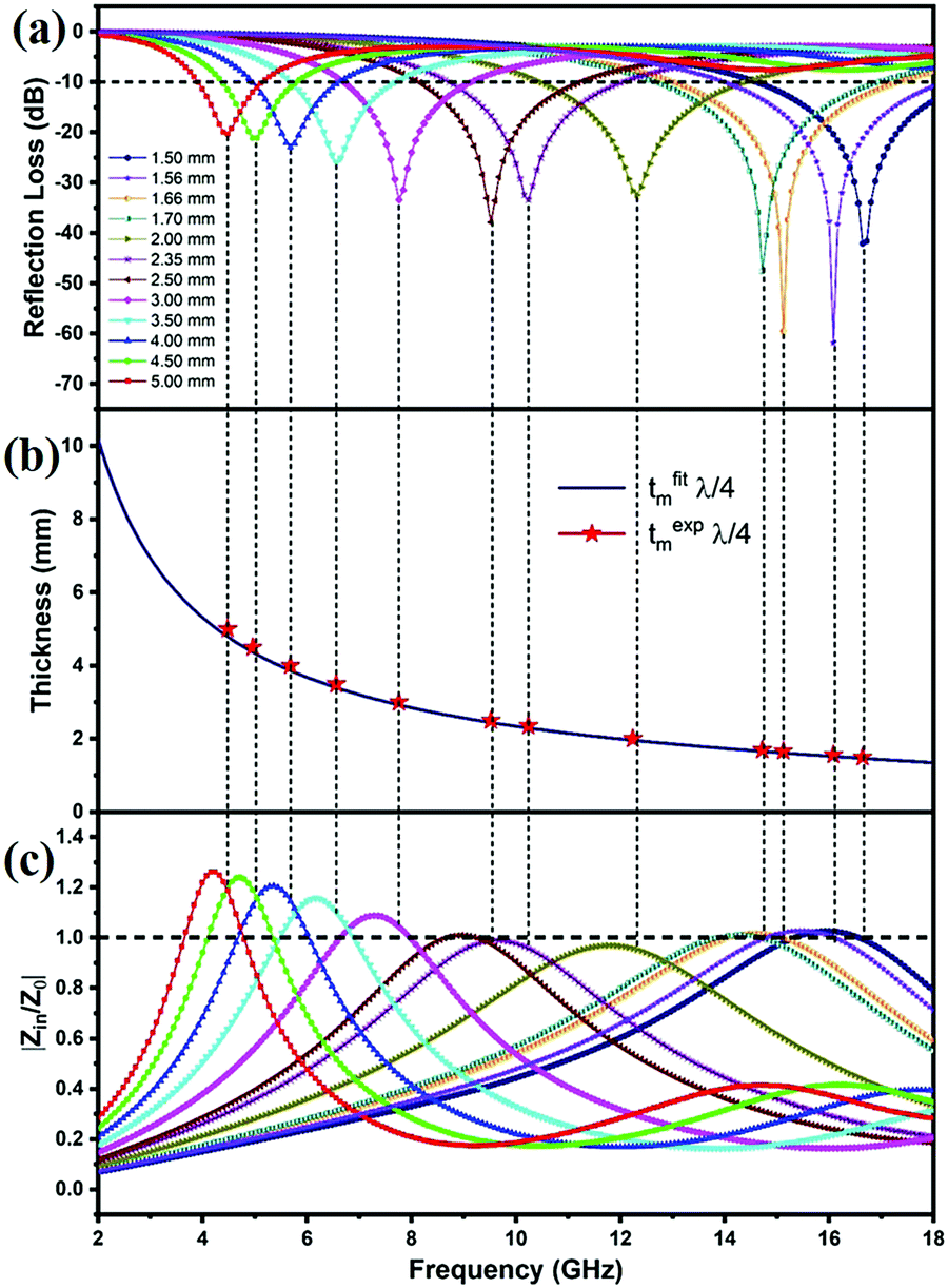 | ||
| Fig. 11 (a) RL–frequency curves of FAC20 with absorber thickness ranging from 1.5 mm to 5 mm. (b) Relationship between tfitm, texpm and peak frequency for FAC20 under the nλ/4 model and (c) the relationship between |Zin/Z0| and frequency for FAC20. | ||
The relationship between RL and impedance matching for FAC20 and FAC30 is shown in Fig. 11(a, c), and Fig. S5(a, c) (ESI†), respectively. The graphs clearly show that Z values closer to 1 resulted in the optimal RL values. At a thickness of 1.56 mm for FAC20, the Z value is ∼1, and hence the highest RL of −61.86 dB was obtained.
The FAC20 absorber showed the best MW absorption properties among the samples. The mechanism for this superior performance can be explained as shown in Scheme 1. Firstly, 20 wt% AC was found to be the optimum quantity in CF/AC composite, given that it resulted in the maximum impedance matching and largest surface area among the samples. The improved Z values allowed a greater quantity of MW to enter the absorber, whereas the large surface area facilitated the maximum interaction of MW with the in situ-grown CF nanoparticles, resulting in higher dielectric and magnetic losses. The dielectric loss mechanism mainly involved (i) dipole polarizations, in which the dipoles formed at the pores and defects present in AC as well at the interface of CF/AC absorb EM energy to orient themselves along the direction of the EM field,57,70 (ii) formation of multiple interfaces among CF nanoparticles, AC and paraffin wax, resulting in enhanced interfacial polarization, and (iii) the conduction losses due to the charge transport through the conductive network of AC71,72 and electron hopping through the defects by absorbing EM energy. Alternatively, the magnetic loss mechanism involves the natural and exchange resonance. Therefore, the CF/AC composite is a promising material for use as an RAM material for stealth applications.
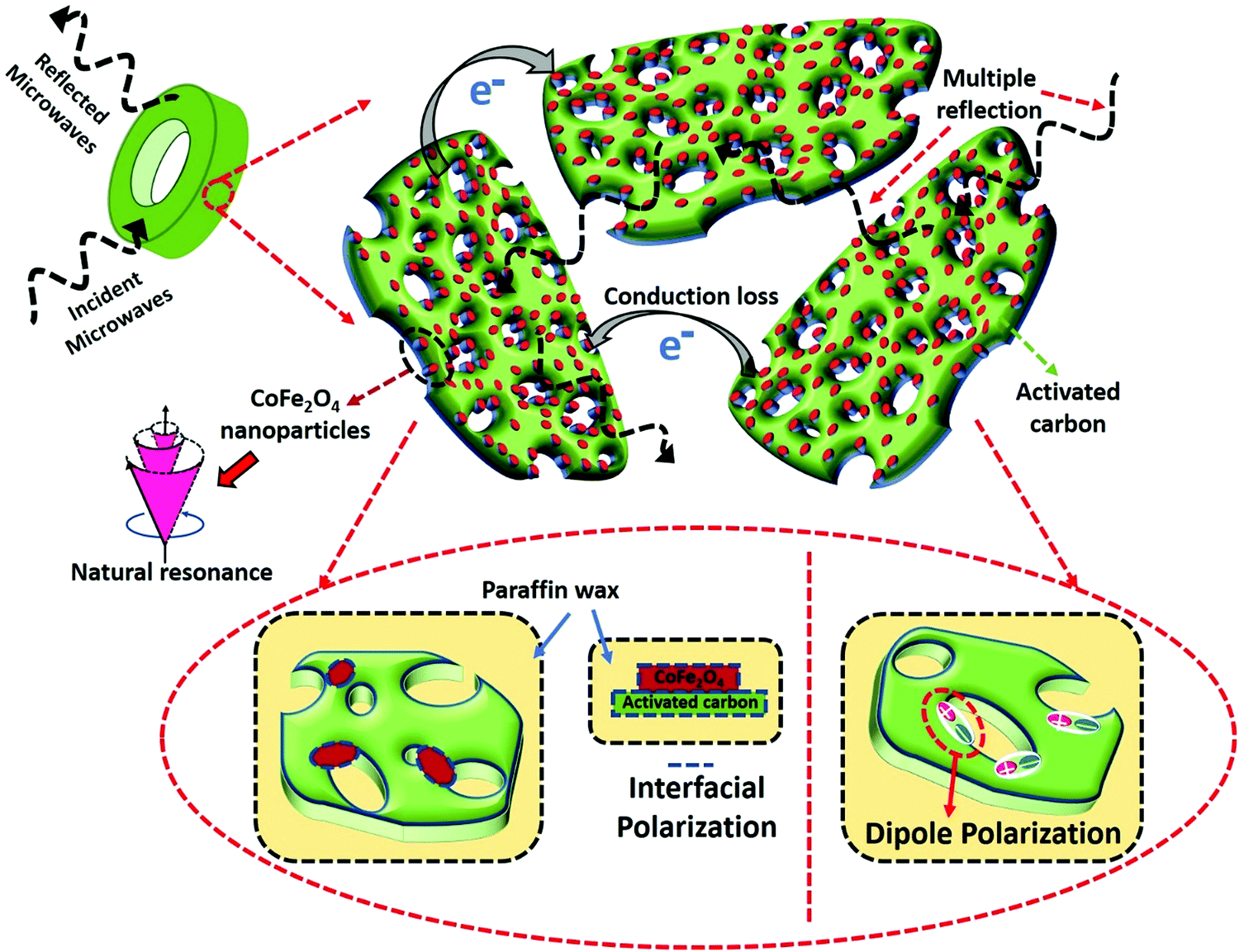 | ||
| Scheme 1 Schematic illustration of the MW absorption mechanism in the CF/AC-paraffin wax composite. | ||
Conclusions
Cobalt ferrite nanoparticles were successfully grown on biomass-derived activated carbon via a facile hydrothermal method. The large specific surface area (SBET) of 502.02 m2 g−1 for FAC20 and 434.82 m2 g−1 for FAC30 suggests that even with the inclusion of CF nanoparticles, sufficient porosity was still maintained in the CF/AC composite, which is highly beneficial to enhance the MW absorption performance. The optimum loading of AC (20 wt%) with CF in FAC20 resulted in an excellent RLmax = −61.86 dB at 16.08 GHz and EAB of 4.02 GHz, at a remarkably thin thickness of 1.56 mm. This excellent MW absorption performance of FAC20 is due to the synergistic effect of magnetic loss, dielectric and interfacial polarisation in the CF/AC absorber, thus providing better impedance matching and large attenuation ability. Therefore, this study demonstrates that CF nanoparticles incorporated with porous biomass AC (FAC20) can be a promising MW absorber for practical applications.Conflicts of interest
The authors declare no competing financial interest.Acknowledgements
Author Praveen Negi is thankful to the Director, National Institute of Technology Kurukshetra for providing Institute fellowship. We are also thankful to Director AMPRI Bhopal for the HRTEM characterization performed at analytical HRTEM laboratory, CSIR-AMPRI, Bhopal through NIT Kurukshetra and AMPRI Bhopal MOU. Authors also acknowledge Abhisek Sharma for implementing RL formulae calculation in python language.References
- P. Liu, Z. Yao, J. Zhou, Z. Yang and L. B. Kong, J. Mater. Chem. C, 2016, 4, 9738–9749 RSC.
- H. Guan, H. Wang, Y. Zhang, C. Dong, G. Chen, Y. Wang and J. Xie, Appl. Surf. Sci., 2018, 447, 261–268 CrossRef CAS.
- Y. Zhao, L. Hao, X. Zhang, S. Tan, H. Li, J. Zheng and G. Ji, Small Sci., 2021, 2100077 Search PubMed.
- F. Wang, W. Gu, J. Chen, Q. Huang, M. Han, G. Wang and G. Ji, J. Mater. Sci. Technol., 2022, 105, 92–100 CrossRef.
- P. Hu, S. Dong, X. Li, J. Chen and P. Hu, ACS Sustainable Chem. Eng., 2020, 8, 10230–10241 CrossRef CAS.
- W. Liu, L. Liu, Z. Yang, J. Xu, Y. Hou and G. Ji, ACS Appl. Mater. Interfaces, 2018, 10, 8965–8975 CrossRef CAS PubMed.
- J. Fang, Y. Shang, Z. Chen, W. Wei, Y. Hu, X. Yue and Z. Jiang, J. Mater. Chem. C, 2017, 5, 4695–4705 RSC.
- X. Qiu, L. Wang, H. Zhu, Y. Guan and Q. Zhang, Nanoscale, 2017, 9, 7408–7418 RSC.
- C. Wang, X. Han, P. Xu, X. Zhang, Y. Du, S. Hu, J. Wang and X. Wang, Appl. Phys. Lett., 2011, 98, 072906 CrossRef.
- L. Deng and M. Han, Appl. Phys. Lett., 2007, 91, 023119 CrossRef.
- Y. Yuan, S. Wei, Y. Liang, Y. Wang, B. Wang, W. Huang, W. Xin and X. Wang, J. Magn. Magn. Mater., 2020, 506, 166791 CrossRef CAS.
- M. Fu, Q. Jiao, Y. Zhao and H. Li, J. Mater. Chem. A, 2014, 2, 735–744 RSC.
- N. Li, G. W. Huang, Y. Q. Li, H. M. Xiao, Q. P. Feng, N. Hu and S. Y. Fu, ACS Appl. Mater. Interfaces, 2017, 9, 2973–2983 CrossRef CAS PubMed.
- M. Dalal, J. M. Greneche, B. Satpati, T. B. Ghzaiel, F. Mazaleyrat, R. S. Ningthoujam and P. K. Chakrabarti, ACS Appl. Mater. Interfaces, 2017, 9, 40831–40845 CrossRef CAS PubMed.
- G. Shen, B. Mei, H. Wu, H. Wei, X. Fang and Y. Xu, J. Phys. Chem. C, 2017, 121, 3846–3853 CrossRef CAS.
- Y. Liu, Z. Chen, Y. Zhang, R. Feng, X. Chen, C. Xiong and L. Dong, ACS Appl. Mater. Interfaces, 2018, 10, 13860–13868 CrossRef CAS PubMed.
- H. B. Zhao, Z. B. Fu, H. B. Chen, M. L. Zhong and C. Y. Wang, ACS Appl. Mater. Interfaces, 2016, 8, 1468–1477 CrossRef CAS PubMed.
- Z. Wu, K. Tian, T. Huang, W. Hu, F. Xie, J. Wang, M. Su and L. Li, ACS Appl. Mater. Interfaces, 2018, 10, 11108–11115 CrossRef CAS PubMed.
- L. Wang, P. Zhou, Y. Guo, J. Zhang, X. Qiu, Y. Guan, M. Yu, H. Zhu and Q. Zhang, RSC Adv., 2019, 9, 9718–9728 RSC.
- P. Negi, A. K. Chhantyal, A. K. Dixit, S. Kumar and A. Kumar, Sustainable Mater. Technol., 2021, 27, e00244 CrossRef CAS.
- Q. Liu, D. Zhang and T. Fan, Appl. Phys. Lett., 2008, 93, 013110 CrossRef.
- L. Liu, S. Yang, H. Hu, T. Zhang, Y. Yuan, Y. Li and X. He, ACS Sustainable Chem. Eng., 2019, 7, 1228–1238 CrossRef CAS.
- H. Wang, Y. Zhang, Q. Wang, C. Jia, P. Cai, G. Chen, C. Dong and H. Guan, RSC Adv., 2019, 9, 9126–9135 RSC.
- G. Li, L. Wang, W. Li and Y. Xu, ChemPhysChem, 2015, 16, 3458–3467 CrossRef CAS PubMed.
- A. Hassan, W. Ding, M. A. Aslam, Y. Bian, Q. Liu and Z. Sheng, J. Mater. Res. Technol., 2020, 9, 12869–12879 CrossRef CAS.
- J. Y. Yusuf, H. Soleimani, L. K. Chuan, Y. K. Sanusi and L. L. Adebayo, J. Alloys Compd., 2021, 888, 161474 CrossRef CAS.
- D. Tahir, H. Heryanto, S. Ilyas, A. N. Fahri, R. Rahmat, M. H. Rahmi, Y. Taryana and S. G. Sukaryo, J. Alloys Compd., 2021, 864, 158780 CrossRef CAS.
- P. Negi and A. Kumar, Nanoscale Adv., 2021, 3, 4196–4206 RSC.
- A. Alazmi, V. Singaravelu, N. M. Batra, J. Smajic, M. Alyami, N. M. Khashab and P. M. F. J. Costa, RSC Adv., 2019, 9, 6299–6309 RSC.
- A. A. Ensafi, H. A. Alinajafi, M. Jafari-Asl, B. Rezaei and F. Ghazaei, Mater. Sci. Eng., C, 2016, 60, 276–284 CrossRef CAS PubMed.
- W. Gu, X. Cui, J. Zheng, J. Yu, Y. Zhao and G. Ji, J. Mater. Sci. Technol., 2021, 67, 265–272 CrossRef.
- Y. Fu, H. Chen, X. Sun and X. Wang, Appl. Catal., B, 2012, 111–112, 280–287 CrossRef CAS.
- Y. Wang, D. Chen, X. Yin, P. Xu, F. Wu and M. He, ACS Appl. Mater. Interfaces, 2015, 7, 26226–26234 CrossRef CAS PubMed.
- S. W. Da Silva, T. F. O. Melo, M. A. G. Soler, E. C. D. Lima, M. F. Da Silva and P. C. Morais, IEEE Trans. Magn., 2003, 39, 2645–2647 CrossRef CAS.
- L. V. Gasparov, D. B. Tanner, D. B. Romero, H. Berger, G. Margaritondo and L. Forró, Phys. Rev. B: Condens. Matter Mater. Phys., 2000, 62, 7939–7944 CrossRef CAS.
- M. A. G. Soler, E. C. D. Lima, S. W. Da Silva, T. F. O. Melo, A. C. M. Pimenta, J. P. Sinnecker, R. B. Azevedo, V. K. Garg, A. C. Oliveira, M. A. Novak and P. C. Morais, Langmuir, 2007, 23, 9611–9617 CrossRef CAS PubMed.
- A. Das, P. Negi, S. K. Joshi and A. Kumar, J. Mater. Sci.: Mater. Electron., 2019, 30, 19325–19334 CrossRef CAS.
- W. Gu, J. Sheng, Q. Huang, G. Wang, J. Chen and G. Ji, Nano-Micro Lett., 2021, 13, 102 CrossRef CAS PubMed.
- V. C. Tung, M. J. Allen, Y. Yang and R. B. Kaner, Nat. Nanotechnol., 2009, 4, 25–29 CrossRef CAS PubMed.
- H. Gao, L. Ding, H. Bai, A. Liu, S. Li and L. Li, J. Mater. Chem. A, 2016, 4, 16490–16498 RSC.
- Y. Lü, Y. Wang, H. Li, Y. Lin, Z. Jiang, Z. Xie, Q. Kuang and L. Zheng, ACS Appl. Mater. Interfaces, 2015, 7, 13604–13611 CrossRef PubMed.
- K. S. W. Sing, D. H. Everett, R. A. W. Haul, L. Moscou, R. A. Pierotti, J. Rouquerol and T. Siemieniewska, Pure Appl. Chem., 1985, 57, 603–619 CAS.
- J. L. Ortiz-Quiñonez, U. Pal and M. S. Villanueva, ACS Omega, 2018, 3, 14986–15001 CrossRef PubMed.
- R. Shu, Y. Wu, Z. Li, J. Zhang, Z. Wan, Y. Liu and M. Zheng, Compos. Sci. Technol., 2019, 184, 107839 CrossRef CAS.
- R. Shu, J. Zhang, Y. Wu, Z. Wan and X. Li, Nanoscale, 2021, 13, 4485–4495 RSC.
- S. R. Naik and A. V. Salker, J. Mater. Chem., 2012, 22, 2740–2750 RSC.
- R. S. Yadav, I. Kuřitka, J. Vilcakova, J. Havlica, L. Kalina, P. Urbánek, M. Machovsky, D. Skoda, M. Masař and M. Holek, Ultrason. Sonochem., 2018, 40, 773–783 CrossRef CAS PubMed.
- R. S. Yadav, I. Kuřitka, J. Vilcakova, J. Havlica, J. Masilko, L. Kalina, J. Tkacz, J. Švec, V. Enev and M. Hajdúchová, Adv. Nat. Sci.: Nanosci. Nanotechnol., 2017, 8, 045002 Search PubMed.
- X. Liu, Y. Chen, C. Hao, J. Ye, R. Yu and D. Huang, Composites, Part A, 2016, 89, 40–46 CrossRef CAS.
- X. J. Zhang, G. S. Wang, W. Q. Cao, Y. Z. Wei, J. F. Liang, L. Guo and M. S. Cao, ACS Appl. Mater. Interfaces, 2014, 6, 7471–7478 CrossRef CAS PubMed.
- G. Fang, C. Liu, Y. Yang, K. Peng, Y. Cao, T. Jiang, Y. Zhang and Y. Zhang, ACS Appl. Mater. Interfaces, 2021, 13, 37517–37526 CrossRef CAS PubMed.
- Y. Du, W. Liu, R. Qiang, Y. Wang, X. Han, J. Ma and P. Xu, ACS Appl. Mater. Interfaces, 2014, 6, 12997–13006 CrossRef CAS PubMed.
- M. Zhang, C. Han, W. Q. Cao, M. S. Cao, H. J. Yang and J. Yuan, Nano-Micro Lett., 2021, 13, 27 CrossRef PubMed.
- J. Chen, J. Zheng, F. Wang, Q. Huang and G. Ji, Carbon, 2021, 174, 509–517 CrossRef CAS.
- M. Ning, B. Kuang, Z. Hou, L. Wang, J. Li, Y. Zhao and H. Jin, Appl. Surf. Sci., 2019, 470, 899–907 CrossRef CAS.
- H. J. Yang, W. Q. Cao, D. Q. Zhang, T. J. Su, H. L. Shi, W. Z. Wang, J. Yuan and M. S. Cao, ACS Appl. Mater. Interfaces, 2015, 7, 7073–7077 CrossRef CAS PubMed.
- X. Wang, W. Cao, M. Cao and J. Yuan, Adv. Mater., 2020, 32, 2002112 CrossRef CAS PubMed.
- J. Ma, J. Li, X. Ni, X. Zhang and J. Huang, Appl. Phys. Lett., 2009, 95, 1–4 Search PubMed.
- H. Wang, Y. Dai, W. Gong, D. Geng, S. Ma, D. Li, W. Liu and Z. Zhang, Appl. Phys. Lett., 2013, 102, 223113 CrossRef.
- M. Zhang, H. J. Yang, Y. Li, W. Q. Cao, X. Y. Fang, J. Yuan and M. S. Cao, Appl. Phys. Lett., 2019, 115, 1–5 Search PubMed.
- X. X. Wang, T. Ma, J. C. Shu and M. S. Cao, Chem. Eng. J., 2018, 332, 321–330 CrossRef CAS.
- P. Toneguzzo, G. Viau, O. Acher, F. Fiévet-Vincent and F. Fiévet, Adv. Mater., 1998, 10, 1032–1035 CrossRef CAS.
- L. Wang, Y. Guan, X. Qiu, H. Zhu, S. Pan, M. Yu and Q. Zhang, Chem. Eng. J., 2017, 326, 945–955 CrossRef CAS.
- F. Wang, W. Gu, J. Chen, Y. Wu, M. Zhou, S. Tang, X. Cao, P. Zhang and G. Ji, Nano Res., 2021, 1–9 Search PubMed.
- Y. Zhang, X. Wang and M. Cao, Nano Res., 2018, 11, 1426–1436 CrossRef CAS.
- J. Z. He, X. X. Wang, Y. L. Zhang and M. S. Cao, J. Mater. Chem. C, 2016, 4, 7130–7140 RSC.
- X. F. Zhang, P. F. Guan and X. L. Dong, Appl. Phys. Lett., 2010, 96, 1–4 Search PubMed.
- M. S. Cao, X. X. Wang, M. Zhang, J. C. Shu, W. Q. Cao, H. J. Yang, X. Y. Fang and J. Yuan, Adv. Funct. Mater., 2019, 29, 1807398 CrossRef.
- L. Liang, W. Gu, Y. Wu, B. Zhang, G. Wang, Y. Yang and G. Ji, Adv. Mater., 2021, 2106195 Search PubMed.
- M. Cao, X. Wang, W. Cao, X. Fang, B. Wen and J. Yuan, Small, 2018, 14, 1800987 CrossRef PubMed.
- X.-X. Wang, M. Zhang, J.-C. Shu, B. Wen, W.-Q. Cao and M.-S. Cao, Carbon, 2021, 184, 136–145 CrossRef CAS.
- C. Han, M. Zhang, W.-Q. Cao and M.-S. Cao, Carbon, 2021, 171, 953–962 CrossRef CAS.
Footnote |
| † Electronic supplementary information (ESI) available: Particle size distribution graph with TEM images, magnetic hysteresis graph, complex permeability graph, frequency vs. impedance matching curves, and combined graph of RL, Z and thickness for FAC30. See DOI: 10.1039/d1ma01116b |
| This journal is © The Royal Society of Chemistry 2022 |