
 Open Access Article
 This Open Access Article is licensed under a
 Creative Commons Attribution 3.0 Unported Licence
Multicomponent two-layered cathode for thick sintered lithium-ion batteries†
Chen
Cai
,
Ziyang
Nie
and
Gary M.
Koenig
Jr.
 *
*
Department of Chemical Engineering, University of Virginia, 102 Engineers Way, Charlottesville, VA 22904-4741, USA. E-mail: gary.koenig@virginia.edu; Fax: +1-434-982-2658; Tel: +1-434-982-2714
First published on 13th April 2022
Abstract
Higher energy density batteries continue to be pursued by researchers. One general route to increase energy density is to increase electrode thickness, which reduces the relative fraction of the cell allocated to inactive components. One route to fabricate thick electrodes is to use mildly thermally treated, or sintered, electrodes comprising only electroactive materials. In this report, the concept of sintered electrodes comprising two different electroactive components will be reported. Conventional composite electrodes with multiple electroactive materials have previously been investigated with the goal of combining desirable attributes of the different components. Sintered electrodes have additional complexity relative to composite electrodes in that interfaces can be formed during processing, and consideration of the location of the different component materials must be taken into account due to the need for electronic conduction through the electrode matrix to proceed through the electroactive materials themselves. Both additional considerations and outcomes will be discussed in this report where multicomponent sintered electrodes of LiCoO2 and LiMn2O4 were fabricated and characterized.
1. Introduction
Driven by the increasing need for lower cost and higher performance energy storage systems, researchers have been progressing in the understanding and optimization of lithium-ion (Li-ion) battery electrodes.1–3 Controlling the electrode components and their organization that forms the microstructure can improve both energy and power densities at the cell level.4–9 In addition, electrode design elements can in principle be applied broadly to many existing materials or new electrode chemistry as it is reported. With regards to electrode design, two routes to achieve high energy densities at the cell level are to reduce the mass fraction of inactive materials such as conductive additives and binders, and to increase electrode thickness. For both routes there are tradeoffs: electronic conductivity and mechanical flexibility/strength limitations for reducing/eliminating inactive materials and increased mass transfer resistances from using thick electrodes.4,5,7,8,10–12 However, one way to reduce inactive materials in the electrode and to increase thickness is to use electrodes comprised solely of electroactive materials.4–8,10 Such electrodes in some cases undergo a mild thermal treatment to improve the mechanical properties and will be referred to as “sintered electrodes” herein.Sintered electrodes have been reported which are free of inactive conductive additives and binders, with high loadings exceeding 150 mg cm−2 and thicknesses over 500 μm.4,6,7 The electrode microstructure for sintered electrodes does not contain inactive additives in the interstitial regions between particles, and thus sintered electrodes have lower tortuosity than conventional composite electrodes.5,7 However, the electrodes are still very thick, and thus ion transport limitations through the microstructure and electron transport through the electrode matrix can result in high polarization and rate capability limitations.5,7,8 Because electron conduction through the electrode matrix must proceed through the electroactive material itself in sintered electrodes, materials with relatively high electronic conductivity across the range of extents of lithiation experienced during charge/discharge of the cell are desirable. Thus, cathode materials such as LiCoO2 (LCO) have been used in multiple sintered electrode studies. LCO is well suited to such electrodes due to its relatively high electronic conductivity: reported to range from 10−2 to 102 S cm−1 from Li1CoO2 to Li0.55CoO2.5,13,14
Previous studies with composite cathodes have investigated using multiple cathode materials within the same electrode to improve electrode capabilities or properties.15,16 For example, a composite electrode blend using LiMn2O4 (LMO) and LiNixCo1−x−yAlyO2 (NCA) demonstrated combined advantages of lower cost, higher operating voltage, and better rate capability from the LMO component and higher capacity, longer storage life, and greater stability from the NCA component.15,17 Herein, the concept of combining multiple electrode materials will first be explored in a sintered electrode system. Composite electrodes experience relatively low temperatures during processing, and the individual active material particles (at least before calendaring) are generally separated from one another. In contrast, sintered electrode electroactive material particles have many contact points due to compression during processing, and then are subjected to temperatures which are mild for sintering but much higher than composite electrode solvent removal temperatures. Ideally, the benefits previously observed for multicomponent composite electrodes would translate directly to sintered electrodes; however, the dissimilar materials processed in direct contact with one another may result in unique considerations that will be reported in this manuscript. In addition, as described above for thick sintered electrodes, the electronic conductivity through the electrode matrix is dependent upon the electrode active material itself. Thus, LCO was chosen as one of the constituents due to its relatively high electronic conductivity as discussed earlier.1,5,6,13,14 For the second material in this initial study, the cathode material LMO was chosen. LMO has been used commercially in composite electrodes, and has advantages relative to LCO with regards to cost due to the higher relative abundance of Mn compared to Co, and may also have environmental advantages.15,18,19 However, the low electronic conductivity of LMO results in high polarization and limited rate capability in a thick sintered electrode system.20 Thus, combinations of LMO and LCO will be explored as a multicomponent thick sintered electrode in this report.
For this study of sintered cathodes containing both LMO and LCO, three different situations will be described. The first is a homogeneous blend, where powders of the two materials are blended together and then processed into a sintered electrode, which will be referred to as “Blend” (Fig. 1a). For the other two cases, the same relative fraction of materials as the homogeneous blend were used, however the powders were segregated into two separate layers. Then, the two-layer sintered electrode was fabricated into a cell where either the LMO component was on the current collector side (Fig. 1b, referred to as “CC:LMO:LCO”) or the LCO component was on the current collector side (Fig. 1c, referred to as “CC:LCO:LMO”). Previous reports with sintered electrodes have suggested that the progression of lithiation/delithiation within the electrode as a function of electrode depth are dependent on the relevant electronic and ionic transport restrictions in the system.4–7 Thus, the drastically different electronic conductivity of LMO and LCO provided a system to assess how the location of the electronically conductive material layer influenced electrochemical outcomes for the cell. The results for these three systems will be discussed in the context of electrochemical characterization and pseudo-two-dimensional (P2D) simulations of the electrochemical cells.
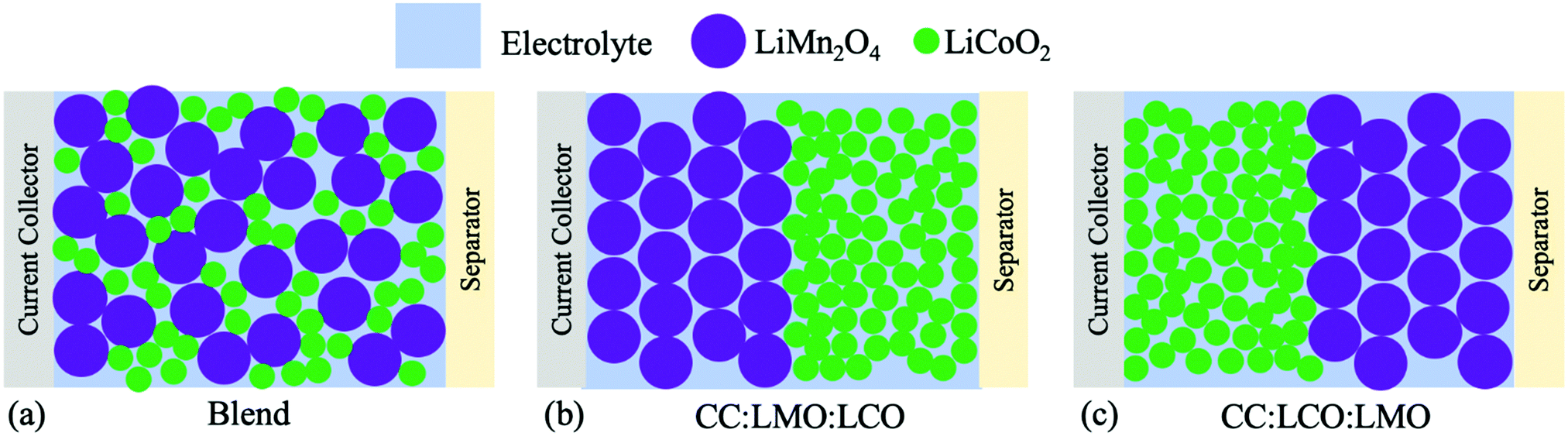 | ||
| Fig. 1 Illustrations of the sintered cell cathode structures in this study, where the situations were (a) homogenous blend of LMO and LCO (“Blend”), (b) LMO next to current collector and LCO next to separator (“CC:LMO:LCO”), and (c) LMO next to separator and LCO next to current collector (“CC:LCO:LMO”). In all cases the total mass of the LMO and LCO in the electrodes was the same. | ||
2. Materials and methods
2.1 Active material powder synthesis
LiMn2O4 (LMO) active material powder was synthesized according to previous reports.20,21 100 mM of sodium oxalate (Na2C2O4, Fisher Chemical) and 10 mM of sodium citrate dihydrate (Na3C6O7H5·2H2O, Sigma-Aldrich), were dissolved into 400 mL of deionized (DI) water at the same time using a 1000 mL beaker. Within a separate 1000 mL beaker 100 mM of manganese sulfate monohydrate (MnC2O4·2H2O, Fisher Chemical) was dissolved into 400 mL DI water. The two solutions were heated to 60 °C followed by pouring the manganese sulfate solution into the oxalate solution all at once. The reaction was allowed to proceed for 30 minutes at 60 °C and 300 rpm. The precipitate was then collected via vacuum filtration before rinsing with 1.6 L of DI water. The powder cake was dried at 80 °C overnight in air. The resulting precipitate MnC2O4·2H2O was then mixed with Li2CO3 (Fisher Chemical) with a targeted molar ratio of Li![[thin space (1/6-em)]](https://www.rsc.org/images/entities/char_2009.gif) :Mn of 1.05:2. The calcination temperature profile used was to ramp the temperature up to 900 °C at a rate of 1 °C min−1, hold at 900 °C for 6 h, ramp the temperature down to 700 °C at 1 °C min−1, hold at 700 °C for 10 h, and then ramp the temperature down to room temperature at a cooling rate of 1 °C min−1.
:Mn of 1.05:2. The calcination temperature profile used was to ramp the temperature up to 900 °C at a rate of 1 °C min−1, hold at 900 °C for 6 h, ramp the temperature down to 700 °C at 1 °C min−1, hold at 700 °C for 10 h, and then ramp the temperature down to room temperature at a cooling rate of 1 °C min−1.
For LiCoO2 (LCO), the electroactive material was also synthesized from an oxalate precursor precipitate.4,6,7 200 mM of each sodium oxalate and cobalt sulfate heptahydrate (CoSO4·7H2O, Acros Organics) were dissolved separately into 400 mL of deionized (DI) water in 2 beakers with volumes of 1000 mL. Both solutions were preheated to 60 °C, followed by adding the cobalt sulfate solution into the oxalate solution all at once. The reaction solution was maintained at 60 °C and stirred at 300 rpm for the entire 30 minutes reaction duration. The solution containing the precipitates was then processed using vacuum filtration to collect the solid particles. After rinsing with 1.6 L of DI water, the powder cake was dried at 80 °C overnight in an air atmosphere. The resulting CoC2O4·2H2O was blended with Li2CO3 (Fisher Chemical) at a targeted molar ratio of 1.05:1 Li:Co using a mortar and pestle by hand for 10 minutes. After the blended powder was transferred into the furnace (Carbolite CWF 1300), it was heated with a ramp rate of 1 °C min−1 to 800 °C without a hold at the high temperature and allowed to cool down to room temperature without control over the cooling rate. The resulting LCO was then ball-milled (Fritsch Pulverisette 7 planetary ball miller) with 4.8 mm zirconia beads for 5 h and 300 rpm with a powder to bead mass ratio ∼1:5. Typical quantities loaded into the jar were ∼4 g of LCO and ∼20 g of beads (corresponding to 57 beads).
2.2 Active material powder synthesis
Scanning electron micrographs (SEM) and energy dispersive X-ray spectroscopy (EDS) were conducted using a FEI Quantum 650. Primary particle sizes were measured for 20 particles in SEM images for both active material powder and sintered pellets to calculate the mean primary particles size. Pellets comprised of two layers (LCO and LMO) were mounted such that EDS analysis could be performed through the thickness dimension on the edge of the entire pellet. Powder X-ray diffraction (XRD) patterns were collected using a PANalytical X'pert ProMPD. Crystalline size and strain were calculated from Debye–Scherrer equation using the largest XRD peaks, and Williamson–Hall relations for strain were analyzed using the three largest XRD peaks.222.3 Sintered electrode fabrication
1 g of each electrochemically active material powder (LMO or LCO) was mixed with 2 mL of 1 wt% polyvinyl butyral (PVB, Pfaltz & Bauer) in ethanol, separately, and the suspension was blended by hand with mortar and pestle until it appeared dry. All sintered electrodes were prepared with the PVB-coated active material powders.For the blend sintered cathode case, 0.116 g of PVB-coated LCO and 0.100 g of PVB-coated LMO were mixed with mortar and pestle by hand for 5 minutes. The masses were chosen to result in an approximately 50% by volume blend of the two materials (LCO crystal density is 5.0 g cm−3,23 while LMO crystal density is 4.3 g cm−324). The resulting blended powder was loaded into a circular pellet die (Carver) with an area of 1.33 cm2 and pressed at 430 MPa for 2 min with a hydraulic press (Carver). For both the CC:LMO:LCO and CC:LCO:LMO cases, 0.116 g of LCO was first loaded in to the pellet die with mild pressure by hand to flatten the powder surface, and then 0.1 g of LMO was loaded above the LCO powder before using the same pressure treatment with the hydraulic press as for all other samples. The pressed pellet was then transferred into the furnace with air atmosphere and heated at a ramp rate of 1 °C min−1 to 600 °C, held at 600 °C for 1 h, then cooled back to room temperature at a rate of 1 °C min−1. After heating, pellet thicknesses were measured with calipers and varied between of 510–530 μm, and the mass for all samples ranged between 0.204–0.209 g. The approximate geometric pore/void fraction was 34% for the total pellet thickness (it is noted that pellets pressed with only LMO or LCO powders and heated with the same furnace profile also had an approximate geometric pore/void volume of 34%). The 1.16 mass ratio resulted in the same total thickness for all pellets and the same thickness for the LCO and LMO individual layers for the two-layer cathodes. For pure LCO and LMO pellets, 0.2 g of coated powder was loaded into the pellet die and then followed the same procedure with regards to hydraulic compression and heat treatment. The final pure material pellets had porosity of ∼34%, mass of 0.197 g, and thicknesses of 470 μm and 540 μm, respectively. It is noted here that 600 °C was chosen as the processing temperature for the sintered cathodes in an effort to keep the temperature as low as possible to avoid any possible new material/composition interface formation. Temperatures of 400 and 500 °C were also attempted but resulted in fragile pellets which collapsed during handling.
For the anode, Li4Ti5O12 (LTO, NEI corporation) was used as the electroactive material for all sintered electrode cells. Detailed characterization of this material, including its use in sintered electrode cells can be found in previous reports.4–6 0.2 g of PVB-coated LTO was processed following the same procedure described for the cathode materials above, and the final pellets had thicknesses ranging from 700–720 μm and masses ranging from 0.194–0.199 g, with a geometric pore/void fraction of 40%.
2.4 Composite electrode fabrication
Cathode material powders (100% LCO, 100% LMO, or a mix of 54% LCO 46% LMO by mass) were mixed with polyvinyl pyrrolidone (PVP, Sigma Aldrich, 360 kDa molecular weight) dissolved in ethanol (Fisher) and acetylene carbon black (Alfa Aesar) with a mass ratio of 8:1:1 active material:PVP:carbon black. While PVP is not as commonly used as a Li-ion electrode binder, in this work PVP was used as the binder for a conductive layer adhered between the sintered electrodes and current collectors (described in the next paragraph). PVP was chosen as the binder because it enabled the use of ethanol as a solvent, which resulted in much faster drying and processing of the sintered electrode cells. PVP was then used for processing of composite electrodes to ensure consistency of the binder used across different cell systems. The components were combined via a slurry mixer (Thinky AR-100) at 2000 rpm for 4 minutes, followed by 5 minutes of sonication, and then 4 additional minutes in the slurry mixer at 2000 rpm. The slurry was coated onto an aluminum foil using a 400 μm gap doctor blade. The electrodes were dried in air for 0.5 h followed by vacuum drying at 50 °C for 1 h. Circular shaped 1.33 cm2 cathode discs were punched out, with resulting loadings across all electrodes ranging between 1.4–4.5 mg cm−2.
2.5 Cell fabrication and electrochemical evaluation
For sintered electrode cells, to reduce interfacial resistance between the sintered pellet electrode and current collector, conductive carbon paste comprised of acetylene carbon black (Alfa Aesar) and PVP with a mass ratio of 1:1 in ethanol was used between the electrode and current collector (bottom plate for the cathode and metal disc spacer for the anode) of the 2032-type cell. The attached pellet sintered electrodes were dried at 50 °C for 1 hour under vacuum to drive off the ethanol. To assemble the coin cell, 1.2 M LiPF6 in 3:7 ethylene carbonate:ethyl methyl carbonate (Gotion) was used as the electrolyte and glass fiber (Fisher) was used as separator. The cell was cycled between 1.0 V to 2.8 V (cell voltage) with a multichannel battery cycler (MACCOR), where 142.5 mA g−1 cathode electroactive material was assumed to be 1C, and C rates were adjusted based on the actual mass of cathode material in the coin cell. For the sintered electrode full cells, 1C would correspond to ∼21 mA cm−2.
For composite electrode cells, Li foil and Celgard 2325 were used as anode and separator, and the same electrolyte was used as that in the sintered electrode cells. All composite cathode cells were cycled between 2.5 V to 4.3 V (versus Li/Li+) where 137, 148, and 142.5 mA g−1 cathode material were assumed to be 1C for 100% LCO, 100% LMO, or 54% LCO 46% LMO by mass, respectively.
It is noted here that for rate capability evaluation, sintered electrodes were in general cycled at lower C rates compared to composite electrodes. This was due to the major differences between the two types of electrodes with regards to electrode thickness and electroactive material loading. Even with the removal of inactive components from the electrode microstructure the sintered electrodes are much thicker, which limits higher C-rate cycling. Sintered electrodes also have approximately an order of magnitude greater areal loading of active material, which means the areal current densities are approximately and order of magnitude higher for the same C-rate.
2.6 P2D simulation
The P2D simulation was based on the reports from Newman,25,26 and specific modifications to adapt the model to sintered electrode systems can be found in previous reports.5 For the two-layered sintered cathode simulations, the cathode was divided into 2 regions of LCO and LMO with equal thickness of 255 μm. The initial composition of the assembled cell electroactive materials was assumed to correspond to Li4Ti5O12, LiMn2O4, and LiCoO2 for the respective materials. The simulation then proceeded with charging the cell to 2.8 V at a current density that would correspond to C/50. This was the initial condition before simulating discharge at C/50. The end of discharge simulation at C/50 was then used as the initial condition for simulating the charge at C/20. Then the end of charge at C/20 was used as the initial condition for simulating the discharge at C/20. All physical properties of LCO, LMO, LTO, separator and electrolyte can be found in Tables S1 and S2 (ESI†). As will be discussed in the following sections, the blend electrode was not simulated. The voltage plateau below 3 V (versus Li/Li+) of LMO was also not considered in the simulation even though the voltage window used in simulation was 1.0 V to 2.8 V (cell, equivalent to 2.86–4.36 V versus Li/Li+).3. Results and discussions
3.1. Materials characterization
SEM images of LMO and LCO active material powder can be found in Fig. S1 and S2 (ESI†). For sintered electrodes, generally small (<1000 nm) primary particles have been used in efforts to increase electrochemically active surface area and decrease solid-state transport resistances.4,6 Thus, for LCO the active material powder was ball-milled before pressing into a pellet and sintering. The ball-milled LCO powder had primary particle lengths of 220 ± 70 nm, and after sintering the size was determined to be 240 ± 90 nm (averages and standard deviations from measurements of 20 independent particles in the SEM images), suggesting the primary particle size was maintained after the thermal treatment. For LMO active material powder before sintering, the primary particle length was 780 ± 170 nm, and after sintering the size was determined to be 760 ± 190 nm, again suggesting the primary particle size was not impacted by the mild sintering process. Note that the after sintering primary particle measurements reported were for pure LCO or LMO particle contacts, and not for the blend system.The XRD patterns of the blend cathode before and after the thermal treatment can be found in Fig. S3 (ESI†). When looking at the pellet before sintering, the XRD pattern reflected a blend of both LMO and LCO materials, with distinct peaks present for each material and consistent with previous reports.20,21,27 LMO had an Fd![[3 with combining macron]](https://www.rsc.org/images/entities/char_0033_0304.gif) m spinel structure28 with a crystalline size of ∼50 nm and strain of 0.0027 determined from XRD analysis; LCO had a Rm layered structure29 with a crystalline size of ∼72 nm and strain of 0.0016 determined from XRD analysis, and the peaks were consistent with contributions from each of these phases. Although the heat treatment was relatively mild (heated to 600 °C and held for 1 h), after heat treatment the LCO peaks shifted towards lower values, suggesting an increased lattice size for layered LCO, which could possibly be attributed to the substitution of Co (ionic radius of 56 pm) by Mn (ionic radius of 63 pm).30,31 Similarly, all the LMO features shifted to increasing values, suggesting a decreased lattice size for spinel LMO, where Co may have been incorporated into the LMO lattice as well.32 In addition, an impurity peak was observed at 31.2°, which was attributed to the formation of Co3O4 phase.33 One possible cause of the impurity in the blend pellet could be diffusion of Li+ from the LCO to the LMO during the heat treatment process, resulting in loss of Li from the LCO and formation of the Co3O4 impurity. The results of the XRD analysis suggested that a large fraction of the electroactive material had undergone significant modifications of its material properties for the blend pellet, and that new phases and interfaces likely resulted.
m spinel structure28 with a crystalline size of ∼50 nm and strain of 0.0027 determined from XRD analysis; LCO had a Rm layered structure29 with a crystalline size of ∼72 nm and strain of 0.0016 determined from XRD analysis, and the peaks were consistent with contributions from each of these phases. Although the heat treatment was relatively mild (heated to 600 °C and held for 1 h), after heat treatment the LCO peaks shifted towards lower values, suggesting an increased lattice size for layered LCO, which could possibly be attributed to the substitution of Co (ionic radius of 56 pm) by Mn (ionic radius of 63 pm).30,31 Similarly, all the LMO features shifted to increasing values, suggesting a decreased lattice size for spinel LMO, where Co may have been incorporated into the LMO lattice as well.32 In addition, an impurity peak was observed at 31.2°, which was attributed to the formation of Co3O4 phase.33 One possible cause of the impurity in the blend pellet could be diffusion of Li+ from the LCO to the LMO during the heat treatment process, resulting in loss of Li from the LCO and formation of the Co3O4 impurity. The results of the XRD analysis suggested that a large fraction of the electroactive material had undergone significant modifications of its material properties for the blend pellet, and that new phases and interfaces likely resulted.
Such an interface has not been observed after the heat treatment of LCO without LMO directly in contact with the LCO and was not observed for the LCO layer for the two-layer pellet, as can be found in Fig. S3 (ESI†). Heat treated pure LMO had a crystalline size of ∼57 nm and strain of 0.0013 determined from XRD analysis. These results suggest that there was not an obvious change in crystalline size, but there was a reduction in strain. The heat treated pure LCO had a crystalline size of ∼49 nm and strain of 0.0013 determined from XRD analysis. Both the crystalline size and strain were decreased for the heat treatment of the LCO powder.
To further investigate LCO–LMO contact regions after the thermal treatment, SEM and EDS analysis was conducted at the interface region of the two-layered LCO–LMO pellet (Fig. 2). An EDS map of the edge of the two-layer LCO–LMO pellet (Fig. 2c and d) confirmed the presence of a Mn-rich region (LMO) and Co-rich region (LCO). There was a clear area in the SEM (Fig. 2b) where there was a gradient in Co and Mn composition. This layer was ∼5 μm thick (according to the line scan on the pellet edge in Fig. 2a), or about ∼1% of the total electrode thickness. Given that the total cathode thickness was over 500 μm, the interface was not expected to have much impact on the total electrochemical capacity available within the individual LMO and LCO electrode regions. However, the thickness of the interface region was much greater than individual primary particle sizes for either LMO or LCO. Coupled with the XRD results discussed earlier, this suggested that a significant portion of the blend pellet had co-diffusion of Co and Mn.
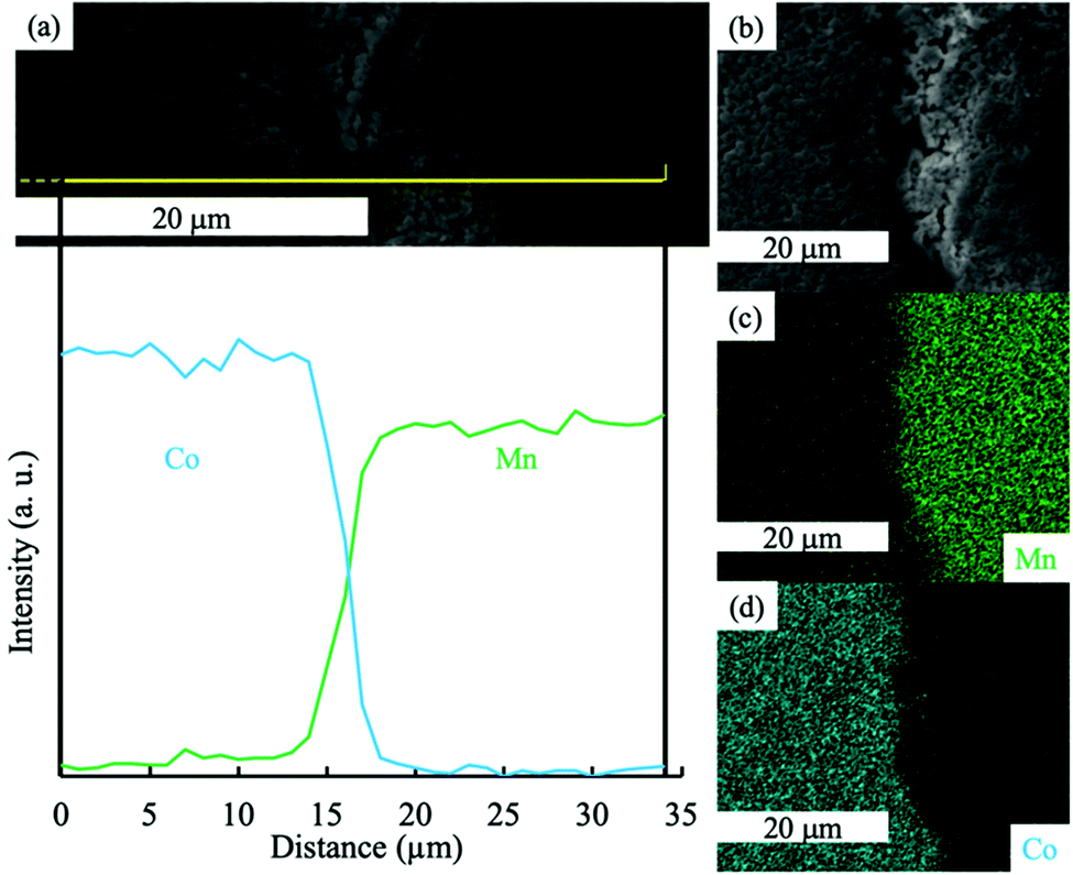 | ||
| Fig. 2 (a) EDS line scan for Co (blue) and Mn (green) for the region indicated with a yellow line in the SEM. (b) SEM of the edge of the two-layer pellet where LMO and LCO regions meet, and the corresponding EDS maps for (c) Mn and (d) Co at the same region as the SEM in (b). | ||
3.2. Electrochemical characterization
For the LCO processed into a sintered electrode and paired with a sintered LTO anode, the cell achieved 144 mA h g−1 LCO for the first C/50 discharge cycle after a C/50 charge cycle (first charge/discharge curves can be found in Fig. S5a, ESI†). A lower rate was used for the sintered electrode cell to minimize impacts of ion transport resistance during initial cell cycling,5 and the voltage window was 1.0 to 2.8 V (cell). The voltage plateau was distinct and its voltage (2.31 V versus LTO, assuming 1.56 V versus Li/Li+,35 roughly 3.87 V versus Li/Li+) was close to that in a composite half cell (∼3.9 V versus Li/Li+), suggesting that the single LCO sintered cathode did not have high electronic polarization even in the absence of conductive additives, consistent with previous results.4–7 The extra 7 mA h g−1 LCO in the sintered electrode compared to the composite electrode could possibly originate from a higher relative charge voltage window for the sintered electrode, and/or possibly more irreversible capacity loss in the composite electrode due to slightly higher electroactive area per mass particles. At C/20, C/10, and C/5, the sintered LCO cell reached 124 mA h g−1 LCO, 83 mA h g−1 LCO, and 39 mA h g−1 LCO, respectively. A rate capability summary can be found in Fig. S5c (ESI†).
LMO in a composite half cell was paired with Li metal and cycled between 2.5 and 4.3 V (vs. Li/Li+) at a charge and discharge rate of C/20 (first charge/discharge curves can be found in Fig. S4c, ESI†). The electroactive material achieved a discharge capacity of 120 mA h g−1 LMO at 3.5 V (before overlithiating beyond lithium extracted during charge into Li1+xMn2O4 phase36), and 184 mA h g−1 LMO at the end of first C/20 discharge. Three distinct voltage plateaus were observed at ∼4.1 V (transition between λ-MnO2 and Li0.5Mn2O4), ∼4.0 V (transition between Li0.5Mn2O4 and LiMn2O4), and ∼2.8 V (transition between LiMn2O4 and Li2Mn2O4), consistent with previous reports for a LMO spinel electrode material paired with Li metal.37–39 After the same heat treatment was applied to LMO powder as was used for sintering of LMO sintered electrode pellets, the LMO capacity was not noticeably impacted across all cycles and rates relative to the material that did not undergo the additional heat treatment. All LMO composite electrodes also had severe capacity fade especially at the first three slow charge/discharge cycles due to the Jahn–Teller distortion upon overlithiation when the lower voltage cutoff of 2.5 V was used (Fig. S4d, ESI†). When the voltage window was restricted to 3.0 V and 4.3 V, initial discharge capacity was reduced, but the capacity fade was mitigated by avoiding LMO overlithiation.
However, when LMO was used as a sintered electrode paired with sintered LTO and charged and discharged at C/50, the initial C/50 discharge capacity only achieved 106 mA h g−1 LMO. There was a flat voltage plateau at ∼2.45 V (which would correspond to ∼4.01 V in the Li half cell with the composite electrode assuming a flat LTO potential of 1.56 V35), however, sintered LMO cathode cell had a significant slope to the polarization curve between ∼2.4 and ∼2.0 V, compared to a much flatter plateau at the corresponding ∼4.0 V region in the Li half cell with the composite electrode. This behavior has been previously reported for LMO sintered electrodes, and has been attributed to the limited electronic conductivity especially near full lithiation of the LMO material – note that LMO has been reported to be ∼4 orders of magnitude lower than LCO in electronic conductivity.5,13,14,20,40–43 The capacity from below 3 V for the composite LMO cell was not present at all in the corresponding regions for the sintered electrode cell, although for the sintered full cell system there was only as much Li+ available from the anode as was intercalated during charge, whereas with the Li metal anode there was an excess Li+ source available to provide the lower potential redox reaction. The sintered LMO electrode also had discharge capacity fade from 106 to 87 mA h g−1 LMO even during the first three cycles at C/50 and down to ∼71 mA h g−1 LMO in the final (15th) cycle which also was at C/50 (capacity retention at different cycling rates can be found in Fig. S5c, ESI†). The capacity fade and limited rate capability of LMO in sintered electrode without conductive carbon was likely due to some combination of the limited electronic conductivity, Jahn–Teller distortion, and Mn dissolution.20,44 The heat treatment during the sintering process was not expected to negatively impact the electrochemical properties of the cathode based on the outcomes for similar processed material in composite electrodes (Fig. S4c and d, ESI†). At C/20, the capacity was only 22 mA h g−1 LMO, and there was almost no capacity at higher rates, which was attributed to the limited electronic conductivity of the material.
The hydraulically pressed and thermally treated blend sintered electrode had very different electrochemical properties relative to the composite electrode. As shown in Fig. 3, at the first C/50 discharge, the capacity only reached 42 mA h g−1, which was much lower compared to the 132 mA h g−1 for the physical blend in the composite half cell above 3 V. The capacity based on the relative loadings in the cathode of the blend sintered cell was 125 mA h g−1. The drastic capacity reduction was likely due to the interface formation from the heat treatment of these materials with dissimilar compositions and phases. Such observation had similarities to a previous study, where an interface formed between dissimilar composition and phase olivine Li1.4Al0.4Ge1.6(PO4)3 and spinel LiMn1.5Ni0.5O4 after thermal treatment when in direct contact with one another.45 In that previous work, an elemental gradient was observed across the interface and impurity GeO2 phase formed, which resulted in very little electrochemical capacity being retained for the cathode material. The crystal structure and compositions in that prior study were very different from this present report, but the formation of a new interface material composition and its detrimental impact on electrochemical capacity were shared outcomes. The low electrochemical capacity and less knowledge of the impact of the new interface region on electrode physical parameters led us not to pursue detailed simulation analysis for the blend case.
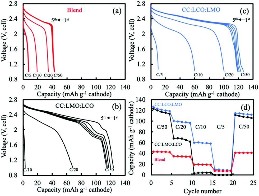 | ||
| Fig. 3 Discharge voltage profiles for sintered electrodes of (a) blend, (b) CC:LMO:LCO, and (c) CC:LCO:LMO. The first 5 discharge curves at C/50 are shown, as well as the higher rates indicted on the plots. Note that C/50 corresponded to a current density of ∼0.44 mA cm−2. (d) The rate capability discharge capacities for the same electrodes in (a–c) with blend (red), CC:LMO:LCO (black), and CC:LCO:LMO (blue). Charge and discharge in all cases were at same C rate/current density. Sintered LTO was the anode paired with all cathodes. | ||
One additional item of note was that although the blend sintered electrode had very low gravimetric capacity at slow rate, there was relatively high retention of that capacity at higher rates for a sintered electrode (rate capability outcomes can be found in Fig. S6, ESI†). One possible contributor to this outcome may have been the Co diffusion into the LMO lattice from the LCO, which could increase the electronic conductivity of the LMO.32 The higher conductivity LCO would also be expected to increase the electronic conductivity of the sintered electrode more generally, at least relative to LMO sintered electrodes.
For the CC:LCO:LMO (LCO in contact with the current collector side), for the first cycle at charge and discharge of C/50 the initial discharge capacity was 127 mA h g−1 cathode (Fig. 3c). Unlike the CC:LMO:LCO case, there was a small amount of electrochemical capacity observed below 1.2 V. This capacity may have been from overlithiation of LMO to form the Li1+xMn2O4 tetragonal phase. A possible source for the Li+ necessary for this low voltage capacity may have been structural instability of LCO. Although both two-layer electrodes were charged to 2.8 V, for CC:LCO:LMO more Li+ was extracted from the LCO layer due to relatively lower electronic overpotential, which may have resulted in some irreversible structural collapse in the LCO layer.46–50 This structural collapse coupled with Li+ extraction may have resulted in some of the Li+ then inserting into the LMO during the lower voltage LMO process on discharge rather than the no longer available small amount of capacity in the LCO phase. At C/20 charge/discharge, a capacity of 101 mA h g−1 cathode was reached, much larger than that of the CC:LMO:LCO. At C/10, 60 mA h g−1 cathode was delivered in contrast with the minimal capacity for the CC:LMO:LCO. Unlike the CC:LMO:LCO case, the unexpected voltage plateau at ∼2 V was not observed. Degradation of LMO was not determined to have had as great of an impact on the voltage profile due to the relative position of LCO and LMO and their different electronic conductivities.
3.3. P2D simulation analysis
For sintered electrodes, the matrix electronic conductivity was provided by the electroactive material only, and the electronic conductivity of intercalation materials has been reported to be dependent upon the degree of lithiation.5,13,14,51 Accurate simulations using the P2D model thus required information on the electronic conductivity as a function of lithiation. For LCO sintered cathodes, the electronic conductivity as a function of degree of lithiation has been reported with relatively consistent values.5,13,14 However, for LMO, the electronic conductivity as a function of lithiation has been reported with conflicting trends.43,52–54 In our previous work,20 a trend of decreasing electronic conductivity with increasing extent of lithiation was found to be consistent with experimental observations for LMO sintered electrode materials. Thus, a literature report with the same trend was used for the P2D model of LMO with regards to the matrix electronic conductivity.52 The interpolated values can be found in Fig. S7 (ESI†).52 The general trend was that fully delithiated LMO has the highest electronic conductivity, with both voltage plateaus having a corresponding flat electronic conductivity, and LMO lithiated to Li1Mn2O4 had the lowest electronic conductivity.52 Li1+xMn2O4 region was not considered due to lack of existing literature data and because the relevant capacity region was not significantly observed for sintered full cells. The electronic conductivity was thus aligned with the OCV of the LMO, or the different phases involved during LMO lithiation/delithiation: the two-phase reaction between spinel λ-MnO2 (∼0.64 mS cm−1) and spinel Li0.5Mn2O4 (∼0.14 mS cm−1) followed by a single-phase reaction proceeding to the LiMn2O4 (∼0.07 mS cm−1). LCO electronic conductivity as a function of lithiation can also be found in Fig. S7b (ESI†), which was ∼4 orders of magnitude greater than that that of LMO for most extents of lithiation.5,13,14 Another assumption for the P2D simulation of two-layer sintered electrodes was the treatment of the interface layer between the LMO and LCO. This was treated as a single discretized point between the LCO and LMO layers and was assumed to be electrochemically inactive and having the same electronic conductivity as the adjacent discretized point towards the current collector direction.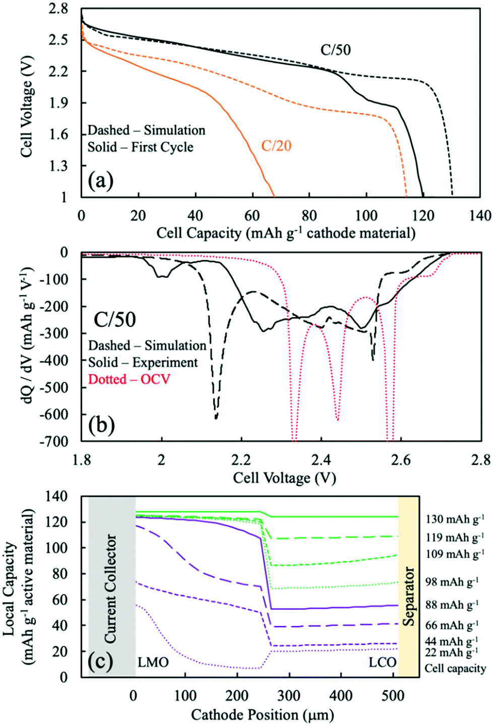 | ||
| Fig. 4 The CC:LMO:LCO case: (a) discharge voltage profile comparison between P2D simulation (dashed) and experimental (solid) at C/50 (black) and C/20 (orange). (b) dQ/dV curves from P2D simulation (black dashed), OCV calculation (red dashed), and experimental (black solid) discharge at C/50. (c) Simulated Li intercalation position across the cathode depth. The purple solid line was chosen as the end of most of the LMO capacity during discharge, and the green dashed line represents the end of the discharge simulation. There are four curves corresponding to 25%, 50%, 75%, and 100% capacity delivered for the components of the discharge with most of the LMO capacity (purple) and with minimal LMO capacity (green). | ||
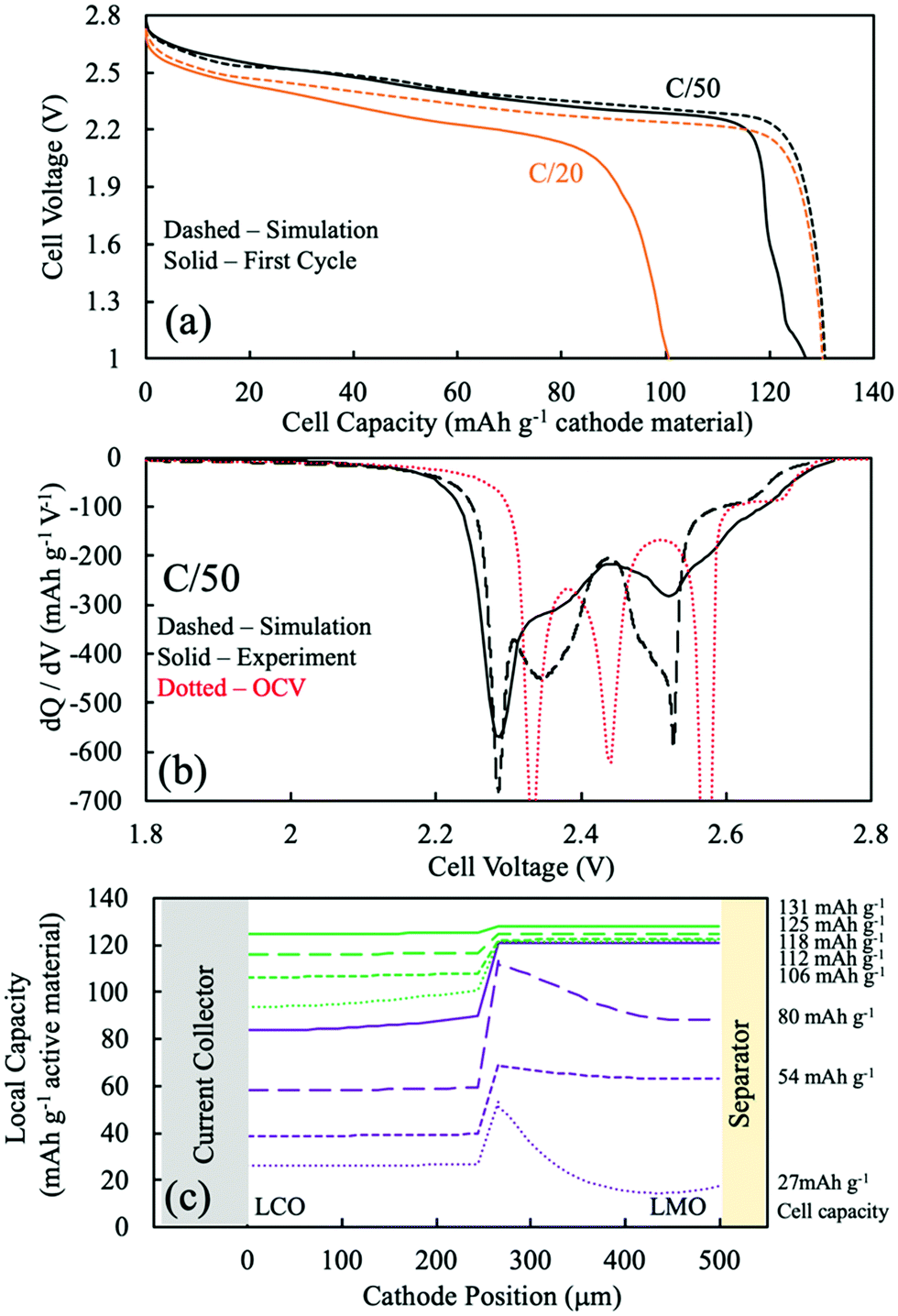
To better assess the overpotentials during discharge for the two-layered CC:LMO:LCO sintered electrodes, a dQ/dV analysis was performed and can be found in Fig. 4b. The first experimental discharge cycle at C/50 and the corresponding simulation was represented by black solid and black dashed curves, respectively. An overpotential-free dQ/dV was calculated using the OCV functions (fitted from composite half cell paired with lithium foil anode) in Table S1 (ESI†) assuming the same mass ratio used for the experimental sample (red dashed curve). The resulting curve was shifted lower by 1.56 V (OCV of LTO redox plateau,35 Fig. S8, ESI†) to reflect an ideal case where if the cell were discharged infinitely slow, then all overpotential sources would became zero and only dictated by the OCV functions of LMO and LCO.
Above 2.6 V (4.16 V vs. Li/Li+) LMO would be expected to hardly provide any capacity based on low rate composite electrode dQ/dV profiles (see Fig. S8, ESI†). In this voltage region, there was a small amount of capacity (∼10 mA h g−1) that mostly should have been contributed by the LCO. The experimental dQ/dV plot had peaks in differential capacity that were shifted to a slightly lower voltage relative to the OCV dQ/dV, but the dQ/dV capacity peaks for the simulation were shifted to much lower voltages. This outcome suggested an underestimated electronic conductivity of LMO for the λ-MnO2 phase, where the matrix electronic resistance of the LMO was expected to account for the lower peak positions in the dQ/dV experiments.
Even though the onset of the first experimental dQ/dV peak was at ∼2.6 V (vs. anode/LTO), similar to the OCV calculation, the magnitude (∼270 mA h g−1 V−1) and position (2.50 V) of this peak were much lower than the OCV calculation (∼1290 mA h g−1 V−1 and 2.57 V). When looking at Fig. S8 (ESI†), the OCV dQ/dV LCO contribution above 2.45 V had differential capacity less than ∼100 mA h g−1 V−1. LMO provided almost all of its discharge capacity associated with its higher voltage plateau between ∼2.6 V and ∼2.5 V (from λ-MnO2 to Li0.5Mn2O4 reaction). This result suggested that the smaller observed experimental peak in this voltage region was indeed from the first higher voltage LMO reaction, but that it was delivered at a lower and more sloped voltage profile due to overpotential in the cell. A probable source of that overpotential would be the low electronic conductivity of the Li0.5Mn2O4 phase. For the dQ/dV curve from the P2D simulation, the LMO started delivering capacity at 2.56 V, a lower voltage than observed experimentally. This result supported an underestimated electronic conductivity of the λ-MnO2 phase because that capacity was delivered experimentally at a higher voltage than simulation.
The second lower voltage discharge dQ/dV peak associated with the LMO material can be observed at 2.44 V (vs. anode/LTO) from the OCV calculation (Fig. S8, ESI†). The corresponding experimental differential capacity was a much broader peak of a smaller magnitude at 2.36 V, which initiated capacity at ∼2.40 V. The offset relative to the OCV dQ/dV peak location for the experimental lower voltage LMO peak compared to the higher voltage one was consistent with the Li1Mn2O4 phase being even more resistive than Li0.5Mn2O4 phase and causing increasing polarization as the discharge proceeded and more LiMn2O4 phase was formed. This outcome was also consistent with previous observations for sintered LMO electrodes.20 From the P2D simulation, the second lower voltage dQ/dV peak attributed to the LMO reaction occurred at 2.40 V and capacity initiated at ∼2.42 V (Fig. 4). These potentials were higher than the experimental results and suggested that the electronic conductivity used for the LiMn2O4 phase in the simulation may have been overestimated.
In the OCV calculation (Fig. S8 and Fig. 4, ESI†), a peak attributed to the LCO phase was observed at 2.34 V. Experimentally, there was instead much broader dQ/dV peaks observed at two locations of 2.25 V and 2.00 V. The experimental peak at 2.25 V was attributed to the high overpotential from the low electronic conductivity in the LMO phase, which the electrons have to pass through before arriving to the LCO layer. The lower experimental dQ/dV peak at 2.00 V was not likely to be from overlithiation of LMO to the Li1+xMn2O4 phase because such capacity was not expected until below ∼1.3 V, and thus this capacity was also attributed to the LCO phase. It is speculated that the capacity at 2.00 V resulted from additional overpotential from a sudden drop in the electronic conductivity of the LMO phase. This may have been due to the Jahn–Teller effect from an induced tetragonal phase, which could be potentially more than one order of magnitude lower electronic conductivity than the spinel phase.55–57
The P2D simulation used an electronic conductivity function that had a decrease near the state of full lithiation of LMO (Fig. S7a, ESI†). This decrease in LMO electronic conductivity shifted the LCO capacity down and resulted in a dQ/dV peak at 2.14 V; however, a second lower dQ/dV peak such as that observed experimentally at 2.00 V was not observed in the simulation. To further explore the possibility of the LCO lithiation resulting in two dQ/dV peaks due to changes in LMO electronic conductivity, the discharge simulations were conducted again with an alternative function for LMO electronic conductivity (for a plot of this function, see Fig. S9a, ESI†). A change was made where the conductivity at near full lithiation of LMO was reduced to a much lower value of 0.012 mS cm−1 (for modified electronic conductivity function, see Table S1, ESI†). With the modified electronic conductivity function for LMO, the simulated voltage had a plateau at 2.0 V, consistent with the experimental outcome (Fig. S9b, ESI†). Although the simulation with the modified LMO electronic conductivity did not perfectly match the experimental discharge profile and dQ/dV, qualitatively the P2D simulation result supported a more dramatic and sudden drop in LMO electronic conductivity at nearly full lithiation during discharge.
The experimental lowest voltage dQ/dV peak provided further insights by monitoring its progression with continued cycling. dQ/dV for the first 5 discharge cycles can be found in Fig. S10a (ESI†). With each cycle the capacity above ∼2.2 V decreased, and the capacity associated with the lowest voltage dQ/dV peak region increased and shifted to lower voltages with each cycle. Each successive discharge proceeded down to 1 V (∼2.65 V vs. Li/Li+), which could have provided sufficient potential to convert some small amount of LMO to the tetragonal Li2Mn2O4 phase (which would be expected at ∼1.2 V; e.g. ∼2.8 V vs. Li/Li+). Formation of this phase would result in Mn valence closer to 3+, where the Jahn–Teller effect becomes more pronounced.33,57–59 Thus, the degradation of LMO would be consistent with even lower electronic conductivity from the LMO layer in the electrode, which would result in more and more capacity in the lowest dQ/dV peak region.
Although obtaining the most accurate electronic conductivity as a function of lithiation for LMO was a challenge, the lithium intercalation position during simulations was expected to be semi-quantitatively or at least qualitatively reflective of the experimental system, because a major determining factor of the electrochemical reaction was the OCV difference of the electroactive materials. Fig. 4c displays the P2D simulated capacity delivered as a function of the depth in the two-layer electrode during different amounts of total capacity delivered from discharge (e.g., as the discharge proceeded). The solid purple curve was when most (93%) of the LMO capacity had been delivered and was a total of 88 mA h g−1 cathode. The other purple dashed lines represent 25%, 50%, and 75% of that 88 mA h g−1 cathode capacity, or correspondingly that percentage progression of the LMO discharge process (though some LCO discharge occurs during this time as well). The green lines then represent 25%, 50%, 75%, and 100% of the remaining capacity delivered in the electrode from 88 mA h g−1 cathode to 130 mA h g−1 cathode, when nearly all the capacity came from the LCO layer. Thus, the discharge was split into the process with LMO discharge (purple) and without LMO discharge (green).
During the process with LMO discharge (purple in Fig. 4c), during the first 25% of delivered capacity roughly the same capacity was delivered from the LCO and LMO layers. This was in part because the highest voltage capacity comes from the LCO phase until the LMO first plateau reaction can proceed. The LMO layer dominates the capacity delivered from the cell as the discharge proceeds through both LMO reaction plateau regions. The LMO layer capacity tended to be delivered first from the current collector region and then propagate towards the separator. This outcome reflected the low electronic conductivity of the LMO, where the most favorable overpotential was generally closer to the current collector. There are two “waves” of the LMO reaction being selectively near the current collector at 25% and 75% of the purple region, where at 50% the separator region caught up due to the more favorable OCV of the higher voltage plateau reaction proceeding nearer the separator region and driving the capacity to catch up near the separator. At the end of the LMO discharge process (purple), the LMO layer had delivered ∼120 mA h g−1 while the LCO layer had only delivered about one third of its capacity. The LCO lithiation profile was more uniform and gradual throughout the LCO layer depth. This more uniform lithiation in the LCO layer was due to the more sloped OCV as a function of lithiation for LCO relative to LMO, where if a region had favorable overpotential and started to react more the OCV driving force of the less reacted LCO regions tended to flatten out the capacity delivered as a function of depth. This capacity delivered as a function of depth from the LCO remained relatively uniform even when the capacity was delivered without LMO (green), although during this part of the discharge process the overpotential of the capacity delivered from the LCO region was very high due to the low electronic conductivity of the nearly fully lithiated LMO phase that the electrons have to traverse before arriving at the LCO layer.
 | ||
| Fig. 5 The CC:LCO:LMO case: (a) discharge voltage profile comparison between P2D simulation (dashed) and experimental (solid) at C/50 (black) and C/20 (orange). (b) dQ/dV curves from P2D simulation (black dashed), OCV calculation (red dashed), and experimental (black solid) discharge at C/50. (c) Simulated Li intercalation position across the cathode depth. The purple solid line was chosen as the end of most of the LMO capacity during discharge, and the green dashed line represents the end of the discharge simulation. There are four curves corresponding to 25%, 50%, 75%, and 100% capacity delivered for the components of the discharge with most of the LMO capacity (purple) and with minimal LMO capacity (green). | ||
dQ/dV analysis was also performed for the CC:LMO:LCO two-layer electrode and can be found in Fig. 5b. The first experimental discharge cycle at C/50 and the corresponding simulation was represented by black solid and dashed curves, respectively. An identical overpotential-free calculated dQ/dV curve was used as discussed for the previous two-layer case since this curve was independent of the relative position of the LMO and LCO and only reflected the thermodynamic potentials of two materials.
Above 2.6 V, the experimental dQ/dV curve resembled the OCV dQ/dV curve. The experimental would be expected to have slightly lower voltages because even if the LCO had minimal electronic resistance, the cell voltage should be smaller due to the overpotentials from the ionic resistance of the cathode and overpotentials contributed from anode. It was speculated this relatively high voltage discharge capacity resulted as a consequence of the LCO in the sintered electrode being charged to 2.8 V (∼4.36 V vs. Li/Li+), because the OCV function did not access above 4.3 V vs. Li/Li+ and thus did not have capacity at as high of a potential as the sintered electrode cell likely experienced experimentally (Fig. S8, ESI†). This speculation was also consistent with the observation of a small amount of capacity below 1.2 V, where LCO may have underwent mild irreversible structural collapse at the higher potential the sintered cathode was subjected to relative to the composite cathodes.49,50
The first experimental dQ/dV peak was at 2.52 V, which was lower than the OCV calculation (2.57 V) and the discrepancy was attributed to the electronically resistive Li0.5Mn2O4 phase. The first experimental dQ/dV peak position was slightly higher than that of experimental dQ/dV of the CC:LMO:LCO case (2.50 V), which possibly originated from the reduced ionic overpotential from a reduced ionic path with LMO being next to separator. The corresponding P2D simulated dQ/dV peak had a much greater peak magnitude but initiated later than the first experimental dQ/dV peak, suggesting an underestimated electronic conductivity of λ-MnO2 phase and overestimated electronic conductivity from Li0.5Mn2O4 phase, which was consistent with the trend observed from the CC:LMO:LCO simulation.
The second experimental dQ/dV peak had an onset at ∼2.45 V, but a peak position was difficult to define and was possibly overlapped with capacity contributed from LCO at lower voltage, and the capacity was delivered at a much lower voltage than the OCV calculation (2.44 V). This observation was consistent with the CC:LMO:LCO case and a previous sintered LMO report where the Li1Mn2O4 phase was suggested to be even more electronically resistive than the values in the electronic conductivity function (Fig. S9, ESI†). The P2D simulated dQ/dV had much greater capacity and more pronounced peak in this voltage region compared to experiment, suggesting an overestimated Li1Mn2O4 phase electronic conductivity in simulations consistent with the CC:LMO:LCO observations.
The experimental LCO peak was assigned at 2.29 V, which had a much greater magnitude, sharper profile, and closer agreement with the corresponding voltage from the OCV calculation (2.34 V) than for the CC:LMO:LCO case. This result suggested the electronic conductivity overpotential contributing to the location of this peak was much smaller, as expected due to the absence of an LMO layer in between the LCO and current collector. The simulated dQ/dV peak position matched the experimental well, suggesting that the LCO electronic conductivity used in the simulation was a more accurate reflection of the LCO material within the cell.5,13,14
Examining the progression of the first five discharge experimental dQ/dV curves (Fig. S10b, ESI†), the peak at below 2.2 V was not observed for the case where LCO was the layer in contact with the current collector. The LMO did still undergo some mild capacity fade, which may have been due to factors such as Mn dissolution or Jahn–Teller distortion.20 For LCO, from the first cycle until the fifth one, the peak shifted from 2.30 V to 2.29 V, the intensity decreased from ∼480 mA h g−1 V−1 to ∼380 mA h g−1 V−1, and the peak became broader. Such capacity fading was consistent with previous reports for structural collapse of the LCO due to overcharge, which could have resulted due to the relatively high potential experienced by the cathodes in the sintered electrode cell.49,50
Analysis of lithium intercalation as a function of cell depth was also extracted from simulations of the CC:LCO:LMO case and can be found in Fig. 5c. The solid purple curve corresponded to when most (∼94%) of the LMO capacity had been delivered and was a total of 118 mA h g−1 cathode. Compared to the CC:LMO:LCO case, 30 mA h g−1 cathode more capacity was discharged, primarily from the LCO layer, due to the absence of electronically resistive LMO layer between the LCO and current collector. Similar to the CC:LMO:LCO case, the LMO had two waves of lithiation/capacity that propagated from the region closest to the current collector towards the region closest to the separator and corresponded to when capacity was extracted from the two different voltage plateaus of the LMO phase. Also consistent with the previous case, the LCO lithiation/capacity was fairly uniform as a function of depth within the LCO layer during all the capacity delivered regions during discharge.
3.4. Multicomponent material sintered electrode considerations
While homogeneously blended composite electrodes with multiple different electroactive material compositions/phases have been reported with beneficial properties,15,17,60 sintered electrodes can be more challenging to implement with multiple compositions and phases. As demonstrated in this study, differences in phase and/or concentration can lead to formation of new interfacial regions. In some cases, such a region could be beneficial if, for example, a third phase with higher electronic conductivity was formed and the electrochemical capacity and OCV of the constituent desired phases was not dramatically impacted. However, in this study and in other cases interfacial regions tend to result in increased resistances and/or loss of electrochemical capacity.45,61,62Composite electrodes with layers of different materials/particle sizes/phases have been reported to result in improved rate capability.63 For sintered electrodes with multiple active materials in a multiple layer architecture, there are potential advantages originating from the spatial arrangement of materials with different potentials associated with their electrochemical reactions and electronic conductivities. From an electronic conductivity perspective, a layer with relatively high electronic conductivity next to the current collector does not limit the rate capability (e.g., CC:LCO:LMO). However, for the scenario where a material layer with low electronic conductivity is next to the current collector, the conductivity needs to approach the same order of magnitude as the ionic conductivity of the electrolyte used or else the electronic conductivity of this material will limit the rate capability of the cell. In Fig. S11 (ESI†) discharge simulations can be found for a CC:LMO:LCO cathode where LMO electronic conductivity was fixed at a value of 0.5 S m−1 (about one order of magnitude higher than literature). With this higher electronic conductivity, the rate capability at rates of C/20 and C/50 was no longer limited by the electronic conductivity of the LMO material layer and nearly all the electrode capacity was accessed, consistent with previous analysis.64,65 This suggests that there may be processing methods such as the addition of electronically conductive coatings to materials such as LMO to aid in achieving higher utilization of the electrode materials.
When using single materials with relatively high electronic conductivity in sintered electrodes such as LCO or LTO,5–7 lithiation/delithiation tended to initiate from the separator and propagated towards the current collector side, in some cases via a front with a pronounced gradient.5–7,66 Such electrode depth/position dependence of the electrochemical reactions may not be desirable. For example, the reaction selectively occurring near the separator might accelerate additional cathode–electrolyte interphase (CEI) formation in this region. The CEI could then potentially impede the pores and restrict the transport of lithium further towards the current collector where there would be additional capacity remaining in the electrode. Also, regardless of CEI complications at high discharge rates the electrolyte concentration will become depleted near the current collector side of the cathode due to ion transport limitations.5,25,66,67 As a result, electrode regions with remaining capacity nearer the current collector can have situations where the electrolyte concentration becomes too low for Li to continue to intercalate, limiting the voltage and capacity of the cell.5–7,12,25,68 Thus, electrode designs with multiple layers may enable strategies to have more capacity from the current collector regions earlier in the discharge process to avoid the later ion transport restrictions that can more severely limit capacity.
4. Conclusions
This study investigated multicomponent sintered electrodes, where the two materials combined in the cathode architecture were LCO and LMO. Homogeneous blending of the two material powders resulted in new interfacial compositions forming during the thermal processing of the electrode and severe reductions in electrochemical capacity. This highlights the importance of considering the formation of new phases during multicomponent sintered electrode processing. When the LCO and LMO were processed as two separate layers, the interfacial component was a relatively small contributor to overall electrode electrochemical properties. Instead, the electrochemical properties resulting from the location of the electrodes on either the current collector or separator side were investigated. Depending on which layer (LCO or LMO) was near the current collector dramatically changed electrochemical properties of the cells, which was attributed to the very different electronic conductivities of the two materials. Simulations provided further insights into the progression of the electrochemical reactions in the cell. For thick sintered electrodes, careful consideration must be given to the thermodynamics (e.g., OCV at different locations at any given point in the discharge progression), and electronic and ionic transport pathways which dramatically influence the spatial location of the lithiation and delithiation reactions. These results provide insights into the design considerations for multicomponent sintered electrode batteries.Conflicts of interest
There are no conflicts to declare.Acknowledgements
This research was supported by the National Science Foundation, from grant CMMI-1825216.References
- J. B. Goodenough, J. Power Sources, 2007, 174, 996–1000 CrossRef CAS.
- J. B. Goodenough and K. S. Park, J. Am. Chem. Soc., 2013, 135, 1167–1176 CrossRef CAS PubMed.
- K. M. Abraham, J. Phys. Chem. Lett., 2015, 6, 830–844 CrossRef CAS PubMed.
- J. P. Robinson, J. J. Ruppert, H. Dong and G. M. Koenig, J. Appl. Electrochem., 2018, 48, 1297–1304 CrossRef CAS.
- C. Cai, Z. Nie, J. P. Robinson, D. S. Hussey, J. M. LaManna, D. L. Jacobson and G. M. Koenig, J. Electrochem. Soc., 2020, 167, 140542 CrossRef CAS PubMed.
- Z. Nie, P. McCormack, H. Z. Bilheux, J. C. Bilheux, J. P. Robinson, J. Nanda and G. M. Koenig, J. Power Sources, 2019, 419, 127–136 CrossRef CAS.
- Z. Nie, S. Ong, D. S. Hussey, J. M. Lamanna, D. L. Jacobson and G. M. Koenig, Mol. Syst. Des. Eng., 2020, 5, 245–256 RSC.
- B. Delattre, R. Amin, J. Sander, J. De Coninck, A. P. Tomsia and Y.-M. Chiang, J. Electrochem. Soc., 2018, 165, A388–A395 CrossRef CAS.
- H. Ning, J. H. Pikul, R. Zhang, X. Li, S. Xu, J. Wang, J. A. Rogers, W. P. King and P. V. Braun, Proc. Natl. Acad. Sci. U. S. A., 2015, 112, 6573–6578 CrossRef CAS PubMed.
- R. Elango, A. Nadeina, F. Cadiou, V. De Andrade, A. Demortière, M. Morcrette and V. Seznec, J. Power Sources, 2021, 488, 229402 CrossRef CAS.
- M. E. Sotomayor, C. de la Torre-Gamarra, B. Levenfeld, J. Y. Sanchez, A. Varez, G. T. Kim, A. Varzi and S. Passerini, J. Power Sources, 2019, 437, 226923 CrossRef CAS.
- K. G. Gallagher, S. E. Trask, C. Bauer, T. Woehrle, S. F. Lux, M. Tschech, P. Lamp, B. J. Polzin, S. Ha, B. Long, Q. Wu, W. Lu, D. W. Dees and A. N. Jansen, J. Electrochem. Soc., 2016, 163, A138–A149 CrossRef CAS.
- S. Levasseur, M. Ménétrier, E. Suard and C. Delmas, Solid State Ionics, 2000, 128, 11–24 CrossRef CAS.
- I. Saadoune and C. Delmas, J. Mater. Chem., 1999, 9, 1135–1140 RSC.
- S. B. Chikkannanavar, D. M. Bernardi and L. Liu, J. Power Sources, 2014, 248, 91–100 CrossRef CAS.
- T. Kobayashi, Y. Kobayashi and H. Miyashiro, J. Mater. Chem. A, 2017, 5, 8653–8661 RSC.
- Y. Dai, L. Cai and R. E. White, J. Power Sources, 2014, 247, 365–376 CrossRef CAS.
- Q. Liu, S. Wang, H. Tan, Z. Yang and J. Zeng, Energies, 2013, 6, 1718–1730 CrossRef CAS.
- S. Ahmed, P. A. Nelson, K. G. Gallagher, N. Susarla and D. W. Dees, J. Power Sources, 2017, 342, 733–740 CrossRef CAS.
- C. Cai and G. M. Koenig, Electrochim. Acta, 2021, 401, 139484 CrossRef.
- C. Cai, H. Dong and G. M. Koenig, Powder Technol., 2021, 394, 214–224 CrossRef CAS.
- V. Mote, Y. Purushotham and B. Dole, J. Theor. Appl. Phys., 2012, 6, 2–9 CrossRef.
- J. Mao, W. Tiedemann and J. Newman, ECS Trans., 2014, 58, 71–81 CrossRef.
- J. Akimoto, Y. Takahashi, N. Kijima and Y. Gotoh, Solid State Ionics, 2004, 172, 491–494 CrossRef CAS.
- T. F. Fuller, J. Electrochem. Soc., 1994, 141, 1 CrossRef CAS.
- M. Doyle, J. Electrochem. Soc., 1996, 143, 1890 CrossRef.
- Z. Qi and G. M. Koenig, ChemistrySelect, 2016, 1, 3992–3999 CrossRef CAS.
- K. S. Yoo, N. W. Cho and Y.-J. Oh, Solid State Ionics, 1998, 113–115, 43–49 CrossRef CAS.
- M. Holzapfel, C. Haak and A. Ott, J. Solid State Chem., 2001, 156, 470–479 CrossRef CAS.
- S. Waki, K. Dokko, T. Itoh, M. Nishizawa, T. Abe and I. Uchida, J. Solid State Electrochem., 2000, 4, 205–209 CrossRef CAS.
- R. Stoyanova, E. Zhecheva and L. Zarkova, Solid State Ionics, 1994, 73, 233–240 CrossRef CAS.
- S. Mandal, R. M. Rojas, J. M. Amarilla, P. Calle, N. V. Kosova, V. F. Anufrienko and J. M. Rojo, Chem. Mater., 2002, 1598–1605 CrossRef CAS.
- Y. Shao-Horn, S. A. Hackney, A. J. Kahaian and M. M. Thackeray, J. Solid State Chem., 2002, 168, 60–68 CrossRef CAS.
- J. Kim, P. Fulmer and A. Manthiram, Mater. Res. Bull., 1999, 34, 571–579 CrossRef CAS.
- K. Ariyoshi, T. Ino and Y. Yamada, J. Electrochem. Soc., 2021, 168, 070555 CrossRef CAS.
- Y. Huang, Y. Dong, S. Li, J. Lee, C. Wang, Z. Zhu, W. Xue, Y. Li and J. Li, Adv. Energy Mater., 2021, 11, 1–21 Search PubMed.
- H. Zhao, X. Liu, C. Cheng, Q. Li, Z. Zhang, Y. Wu, B. Chen and W. Xiong, J. Power Sources, 2015, 282, 118–128 CrossRef CAS.
- A. H. Marincaş, F. Goga, S. A. Dorneanu and P. Ilea, J. Solid State Electrochem., 2020, 24, 473–497 CrossRef.
- B. Slautin, D. Alikin, D. Rosato, D. Pelegov, V. Shur and A. Kholkin, Batteries, 2018, 4, 21 CrossRef.
- M. Park, X. Zhang, M. Chung, G. B. Less and A. M. Sastry, J. Power Sources, 2010, 195, 7904–7929 CrossRef CAS.
- J. Molenda, J. Marzec, K. Świerczek, W. Ojczyk, M. Ziemnicki, M. Molenda, M. Drozdek and R. Dziembaj, Solid State Ionics, 2004, 171, 215–227 CrossRef CAS.
- J. Molenda, J. Marzec, K. Świerczek, D. Pałubiak, W. Ojczyk and M. Ziemnicki, Solid State Ionics, 2004, 175, 297–304 CrossRef CAS.
- S. Yaniamura, H. Koshika, M. Nishizawa, T. Matsue and I. Uchida, J. Solid State Electrochem., 1998, 2, 211–215 CrossRef.
- I. Belharouak, G. M. Koenig, T. Tan, H. Yumoto, N. Ota and K. Amine, J. Electrochem. Soc., 2012, 159, A1165–A1170 CrossRef CAS.
- J. P. Robinson, P. D. Kichambare, J. L. Deiner, R. Miller, M. A. Rottmayer and G. M. Koenig Jr, J. Am. Ceram. Soc., 2018, 101, 1087–1094 CrossRef CAS.
- E. Zhitao, H. Guo, G. Yan, J. Wang, R. Feng, Z. Wang and X. Li, J. Energy Chem., 2021, 55, 524–532 CrossRef.
- P. Pang, Z. Wang, X. Tan, Y. Deng, J. Nan, Z. Xing and H. Li, Electrochim. Acta, 2019, 327, 135018 CrossRef CAS.
- B. J. Hwang, C. Y. Chen, M. Y. Cheng, R. Santhanam and K. Ragavendran, J. Power Sources, 2010, 195, 4255–4265 CrossRef CAS.
- P. Pang, P. Pang, Z. Wang, Y. Deng, J. Nan, Z. Xing and H. Li, ACS Appl. Mater. Interfaces, 2020, 12, 27339–27349 CrossRef CAS PubMed.
- X. Wang, Q. Wu, S. Li, Z. Tong, D. Wang, H. L. Zhuang, X. Wang and Y. Lu, Energy Storage Mater., 2021, 37, 67–76 CrossRef.
- D. Young, A. Ransil, R. Amin, Z. Li and Y. M. Chiang, Adv. Energy Mater., 2013, 3, 1125–1129 CrossRef CAS.
- Q. C. Zhuang, T. Wei, L. L. Du, Y. L. Cui, L. Fang and S. G. Sun, J. Phys. Chem. C, 2010, 114, 8614–8621 CrossRef CAS.
- M. Nishizawa, T. Ise, H. Koshika, T. Itoh and I. Uchida, Chem. Mater., 2000, 12, 1367–1371 CrossRef CAS.
- S. Ziolkiewicz, A. Rougier, G. A. Nazri and C. M. Julien, Electrochem. Soc. Proc., 1998, 97, 145–151 Search PubMed.
- K. Ragavendran, H. Xia, P. Mandal and A. K. Arof, Phys. Chem. Chem. Phys., 2017, 19, 2073–2077 RSC.
- Y. Shimakawa, T. Numata and J. Tabuchi, J. Solid State Chem., 1997, 131, 138–143 CrossRef CAS.
- A. Yamada and M. Tanaka, Mater. Res. Bull., 1995, 30, 715–721 CrossRef CAS.
- Y. Shao-Horn, S. A. Hackney, A. J. Kahaian, K. D. Kepler, E. Skinner, J. T. Vaughey and M. M. Thackeray, J. Power Sources, 1999, 81–82, 496–499 CrossRef CAS.
- M. M. Thackeray, C. S. Johnson, A. J. Kahaian, K. D. Kepler, J. T. Vaughey, Y. Shao-Horn and S. A. Hackney, J. Power Sources, 1999, 81–82, 60–66 CrossRef CAS.
- K. G. Gallagher, S. H. Kang, S. U. Park and S. Y. Han, J. Power Sources, 2011, 196, 9702–9707 CrossRef CAS.
- F. Zheng, M. Kotobuki, S. Song, M. O. Lai and L. Lu, J. Power Sources, 2018, 389, 198–213 CrossRef CAS.
- P. Verma, P. Maire and P. Novák, Electrochim. Acta, 2010, 55, 6332–6341 CrossRef CAS.
- M. Wood, J. Li, Z. Du, C. Daniel, A. R. Dunlop, B. J. Polzin, A. N. Jansen, G. K. Krumdick and D. L. Wood, J. Power Sources, 2021, 515, 230429 CrossRef CAS.
- A. Mistry, S. Trask, A. Dunlop, G. Jeka, B. Polzin, P. P. Mukherjee and V. Srinivasan, J. Electrochem. Soc., 2021, 168, 070536 CrossRef CAS.
- A. N. Mistry, K. Smith and P. P. Mukherjee, ACS Appl. Mater. Interfaces, 2018, 10, 6317–6326 CrossRef CAS PubMed.
- Z. Nie, R. Parai, C. Cai, C. Michaelis, J. M. LaManna, D. S. Hussey, D. L. Jacobson, D. Ghosh and G. M. Koenig, J. Electrochem. Soc., 2021, 168, 060550 CrossRef CAS.
- Z. Nie, R. Parai, C. Cai, D. Ghosh and G. M. Koenig, Mol. Syst. Des. Eng., 2021, 6, 708–712 RSC.
- I. V. Thorat, D. E. Stephenson, N. A. Zacharias, K. Zaghib, J. N. Harb and D. R. Wheeler, J. Power Sources, 2009, 188, 592–600 CrossRef CAS.
Footnote |
| † Electronic supplementary information (ESI) available. See DOI: https://doi.org/10.1039/d1ma01074c |
| This journal is © The Royal Society of Chemistry 2022 |