 Open Access Article
Creative Commons Attribution 3.0 Unported Licence
Consequences of chirality on the response of materials†
Stefan C. J.
Meskers

Molecular Materials and Nanosystems and Institute for Complex Molecular Systems Eindhoven University of Technology P. O. box 513 (STW 4.37), NL 5600 MB, Eindhoven, The Netherlands. E-mail: s.c.j.meskers@tue.nl
First published on 25th January 2022
Abstract
Chirality refers to the absence of a mirror image related symmetry in objects, materials and molecules. As a consequence of the absence of these symmetry elements, chiral materials show a number of properties and effects which are forbidden in achiral materials. Here we review new optical, optoelectronic and mechanical properties that chiral materials can have but are not allowed in mirror symmetric compounds. In particular, we investigate out-of-equilibrium systems where spatial and time-inversion symmetry provides a framework to understand and control electronic transport and molecular rotational motion.
Introduction
Our ability to make new materials with tailored properties has greatly improved. This raises the question of how we can navigate the vast parameter and property space associated with these new materials and their capabilities. From elementary particle physics we can learn that symmetry is an effective tool to classify the large number of sub-atomic particles that have been discovered. For materials science one may hope that consideration of symmetry can bring a similar level of insight. In this contribution we review the relation between mirror image related symmetry or chirality and optoelectronic properties of materials. Apart from basics we will look at photon and electron transport as well as molecular motion in out-of-equilibrium systems.Chirality is a geometrical property of certain objects. An object is said to be chiral when it cannot be superimposed onto its mirror image. A chiral object does not remain invariant under symmetry operations that are improper, i.e. symmetry operations that are described by a transformation matrix with a determinant equal to −1. The improper symmetry operations are spatial inversion, reflections, and rotation-reflections.
A key example of a chiral molecular object is a helix, e.g. the DNA double helix or the protein alpha helix. The static helical structure of a rigid object, such as a screw, affects its motional properties. In a screw, for instance, circular rotational motion is coupled to linear translational motion. As we will discuss in more detail later on, at the microscopic length scale in chiral molecules, a similar coupling can occur e.g. between spin and momentum and between electric and magnetic transition dipoles.
Materials can also be chiral. Here one usually does not refer to the external shape but to the internal structure. Often handedness is associated with a particular length scale. For instance, in a twisted nematic liquid crystal, the helical organization is obvious at the mesoscopic length scale but hardly discernible at the molecular level. In crystalline materials chirality may originate from the special manner in which achiral modules are stacked together. This is for instance the case for monocrystalline chiral materials with a crystal point lattice that is intrinsically chiral (22 out of the 230 crystallographic point groups, arranged in 11 enantiomeric pairs). Here the unit cells are stacked in a helical manner but may themselves be achiral. The chirality of a crystalline material may also originate from the chirality of its constituent molecules. Here the point lattice itself is not chiral, yet the lattice has only suitable symmetry elements that preserve the chirality of e.g. a chiral molecule placed within the unit cell. This latter type of chiral crystal is characteristic of 65 Söhncke groups.1,2 Finally, in amorphous materials of chiral molecules, there is a helical organization of atoms within the molecule but practically no helical order at all larger length scales.
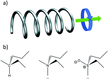
Fig. 1a illustrates another important aspect of chirality: also motion can be chiral. An object moving in a certain direction while simultaneously spinning in a certain rotational direction around its axis of motion is chiral. This notion is key to understanding the chirality of elementary particles such as the photon and the electron as well as their interaction with chiral molecules and materials.
Curiously, the definition of chirality is based on a negation. Such definitions are very rare in natural sciences which usually follow a positivist approach. Perhaps “dark matter” is the only other exception. The negative definition of chirality has three important consequences. First chirality cannot really be observed directly. Rather it is achirality that can be asserted from an experiment showing some invariance within the limited scope set by the experimental error margin. Second, chirality is not a quantity. It cannot be enhanced, augmented or amplified. One material cannot be more chiral than another. Lastly, chirality should be assumed by default. Truly achiral objects are very rare and may exist only as an abstraction. Many molecules which would normally be considered achiral are on an individual basis actually chiral due to e.g. accidental isotopic substitution or temporary conformations that they might adopt. Based on our current understanding of the nuclear forces, the universe as a whole is chiral. In practice chirality is less clear cut than might be expected. When dealing with real molecules or materials one often narrows the view to particular time and length scales.
For instance, a carbon atom with four different substituents is generally considered to be a stereocenter whose presence may make a molecule chiral. A similar arrangement of four different groups including one lone pair around a nitrogen atom is usually not considered as a stereocenter because of the fast umbrella inversion type motion resulting in very rapid racemization on the sub ms timescale.3 So even though the tertiary amine is chiral, one cannot separate the enantiomeric forms on the laboratory time scale and the compound appears as a racemic mixture. When averaging over several molecular length scales, effects of chirality cancel and, on longer length scales, the material appears to be achiral. The sulfoxides provide an interesting intermediate case where enantiomers can be separated, but usually racemize in solution on the timescale of minutes–hours.4
Attempts have been made to quantify manifestations of chirality. Consider for example a molecular structure.5–9 Given a chiral molecule, e.g. the amino acid L-alanine, one can devise a specific measure to quantify how much it differs structurally from its D-enantiomer. Once a measure has been put in place, amplification can also be discussed.10 Such measures are perfectly valid, yet we would like to point out that such quantities are specific to certain aspects of chirality and not to chirality per se. For instance, in the example of alanine, additional assumptions have to be made about what aspect of the molecular structure one wants to evaluate: the distribution of electron density in space or perhaps the position and relative masses of the nuclei or alternatively the van der Waals surface of the molecule. Even the focus on a static structure is already restrictive. A moving object spinning around its direction of motion is already chiral with a time invariant helicity even if the object itself has an achiral static structure.
Consequences of chirality on optical properties
Films of chiral materials can show ‘optical activity’ in their interaction with light. Here optical activity refers to an asymmetry in the response to left and right circularly polarized light. Optical activity includes two different types of optical effects. The first is known as optical rotation. Here the plane of polarization of an incident linearly polarized light beam is rotated upon transmission through the material, either in the clockwise or anticlockwise direction. Optical rotation in isotropic materials is the result of a difference in the refractive index for left and right circularly polarized light and results in a phase difference for left and right waves upon transmission. Optical rotatory dispersion (ORD) refers to measurement of the optical rotation as function of wavelength. Optical activity can also show itself as a difference in the amplitude of left and right polarized waves induced by passage through the medium. Here one speaks of circular dichroism (CD). It is important to note that ORD and CD are not independent. The two phenomena are related via Kramers–Kronig transformation and are both described by the same set of transition probabilities.The different transition probabilities of a chiral molecule with left and right circularly polarized light can be understood intuitively by considering the motion of electrons in a chiral molecule induced by the light, see Fig. 1. In the chiral molecule, excitation of an electron involves a phase locked combination of translation and rotational motion. The translation motion corresponds to an oscillating electric dipole moment on the molecule that couples with the electric field of the light while the rotational component relates to an oscillating magnetic dipole moment that interacts with the magnetic field of the radiation. We recall that circularly polarized light is composed of oscillating electric fields in the direction perpendicular to wavevector combined with oscillating magnetic field components parallel in direction to the electric fields but with a phase difference of ±90°, depending on whether the light is left or right circularly polarized. In a semiclassical picture, an electron oscillating harmonically along a helical path will feature collinear oscillating electric and magnetic dipole moments with a phase difference of ±90° depending on whether the helix is left or right-handed.
When comparing the optical activity of isotropic solutions of small molecules to that of materials, some crucial differences should be noted. For isotropic solutions of molecules, the observation of optical rotation and/or circular dichroism provides direct experimental evidence that the molecules are chiral and that the solution has non-vanishing enantiomeric purity. The left- and right-handed isomers of the chiral molecule must be present in different concentrations. In materials, the direct link between optical activity and chirality is broken; also achiral materials can show differences in their response to left and right circularly polarized light.11–14 This can have several reasons. In the case of solids, the optical setup of the experiment may itself already be chiral.
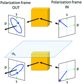
If an incoming light beam approaches a flat surface of an achiral material at an angle, the geometry of the beam and its polarization relative to the crystal can be different for the mirror image of the entire optical experiment including also the source and the detector. Ellipsometry is a well-known example, where an initially linearly polarized light beam acquires a circular component upon specular reflection off the surface of an achiral crystal, see Fig. 2. Second, even if the macroscopic setup of the experiment is ‘achiral’, it has been shown experimentally as well as theoretically that achiral crystals of certain crystal classes (m, mm2, ![[4 with combining macron]](https://www.rsc.org/images/entities/char_0034_0304.gif) , and
, and ![[4 with combining macron]](https://www.rsc.org/images/entities/char_0034_0304.gif) 2m) can show genuine optical activity for a light incident in a specific direction relative to the crystal. Key to understanding this counterintuitive result is that there will be another direction for which the crystal would show the exact opposite optical activity so that in the isotropic average the optical activity will cancel out. Intuitively, the definition of chirality demands that we try all possible orientations to make sure that the two enantiomeric forms cannot be brought to overlap. When measuring the optical rotation of chiral molecules in an isotropic solution, indeed all possible orientations of the molecule relative to the light beam are sampled. In anisotropic condensed matter, however, such comprehensive sampling does not occur naturally and is difficult to enforce. Consequentially, optical activity in solids does not necessarily imply chirality.
2m) can show genuine optical activity for a light incident in a specific direction relative to the crystal. Key to understanding this counterintuitive result is that there will be another direction for which the crystal would show the exact opposite optical activity so that in the isotropic average the optical activity will cancel out. Intuitively, the definition of chirality demands that we try all possible orientations to make sure that the two enantiomeric forms cannot be brought to overlap. When measuring the optical rotation of chiral molecules in an isotropic solution, indeed all possible orientations of the molecule relative to the light beam are sampled. In anisotropic condensed matter, however, such comprehensive sampling does not occur naturally and is difficult to enforce. Consequentially, optical activity in solids does not necessarily imply chirality.
Technically, optical activity requires non-zero elements in the gyrotropic tensor, a second-rank axial tensor that describes the coupling between electrical polarization and magnetization.15 Its elements transform under symmetry operation, as the product of one component of a vector (x, y or z) with one component of a pseudovector (Rx, Ry or Rz). For a particular element (e.g. xRz) to be non-zero, it should transform under the symmetry operations of its point group according to the totally symmetric representation. For optical activity in solution there is a more stringent requirement: the isotropic average of the gyrotropic tensor needs to be totally symmetric, i.e. the trace of the tensor xRx + yRy + zRz should be symmetric. This latter requirement is only fulfilled in chiral point groups.
The optical activity of materials can also manifest itself in reflection of light. Yet here we have to be cautious. Even in reflection experiments on achiral materials, circular polarization effects are very common. A very well-known example is that of ellipsometry on e.g. a silicon wafer. Here the reflection of light under off normal incidence and with linear polarization in a direction of 45° with the normal to the plane of incidence, results in substantial circular polarization in the reflected beam for wavelengths of light inside the absorption region. Here the circular polarization ‘arises’ not from chirality in the reflecting material but from the handedness of the complete optical experiment in particular the direction of the incident beam in combination with the direction of polarization. The mirror image of the complete experiment yields the opposite circular polarization component in the reflected light. A way to avoid these contributions from the chiral optical geometry is to study reflection under normal incidence.
A key example of the influence of chirality on the reflection of light under normal incidence is the circular selective reflection of light by cholesteric liquid crystals.16 If the helical axis of the cholesteric crystals is perpendicular to the reflecting surface and if the wavelength of the light matches the helical pitch length of the chiral nematic, then the circular polarization of light that has the same handedness as the helical molecular arrangement is reflected with unit efficiency while the light with opposite circular polarization is fully transmitted. So, for a cholesteric material, ILL ≠ IRR where I denotes the relative intensity of the reflected light and the two subscript letters indicate the polarization of incoming and reflected waves.
The special nature of this reflection process becomes apparent when considering also the polarization of the reflected light. The light reflected by a left-handed cholesteric material from a left polarized incoming beam under normal incidence is also left circularly polarized. In contrast, light reflected at the surface of an achiral dielectric or metal switches polarization upon reflection and here IRL = ILR.
For a cholesteric material, the polarization conserving, selective reflection is sensitive to the thickness of the film. This indicates that the bulk of the material is involved in the reflection. The process is often referred to as Bragg reflection, as it relies on constructive interference of waves reflected at periodic planes within the material.17,18 Even though the first studies on the chiroptical properties of cholesteric liquid crystals have appeared more than 100 years ago, research on this topic is still very active. It has been recognized that uniform selective reflection requires alignment over macroscopic areas,19–21 and thus circular selective reflection provides an experimental tool to characterize long-range helical order in materials.22,23
An interesting question now is whether for chiral materials we can also have IRL ≠ ILR. So far, our experiments on normal refection off of cholesteric films (thermally annealed films of fluorene type π-conjugated polymers on rubbed polyimide alignment layers) have shown that the degree of circular polarization (ILR − IRL)/(ILR + IRL) for this polarization inverting reflection is more than an order of magnitude smaller than that for the cholesteric type reflection (ILL − IRR)/(ILL + IRR).24,25 The latter, polarization conserving reflection is characterized by degree of polarization on the order of unity.
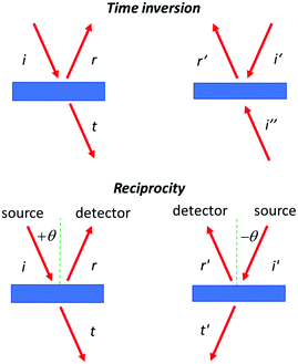
A possible argument against the occurrence of selectivity in the reflection of circularly polarized light with inversion of polarization might be derived from time inversion symmetry. Here one would argue that the reflection of a photon is essentially an elastic collision so that the process should be symmetric under time inversion. Then the equality IRL = ILR should hold for the intensity of the reflected light. This would preclude any circular selectivity in this type of reflection. Yet, as can be seen in Fig. 3, if the reflection is not total, the presence of the transmitted beam makes the original reflection experiment and its time inverted analog actually quite different. In the time inverted case, one has two incoming beams combining into a single reflected wave representing the reversed incident beam i. So, time inversion symmetry in the case of partial reflection does not provide a strict argument against circular selective polarization inverting reflection.
Another possible argument against circular selective polarization inverting reflection might be based on the principle of reciprocity. This we will discuss in the next section.
Optical reciprocity: broken by chirality?
In optics the principle of reciprocity may be phrased as follows. Given a ray of light that has passed from a source through a system and arrived at the detector with a certain intensity, then the same intensity will be recorded after interchanging the positions of the source and the detector.26 As a principle, reciprocity is extremely wide in its scope and has been applied to scattering, reflection and transmission.Optical reciprocity has been found or predicted to break down in some cases.27 The most widely known non-reciprocal behaviour involves static magnetic fields. For instance, the presence of a magnetic field collinear with a beam of light, induces magneto-optical or Faraday rotation of the plane of polarization of the light passing through an achiral medium. Upon exchanging the source and the detector, or alternatively changing the direction of the collinear magnetic field, the sign of the optical rotation will invert. Note that for natural optical activity, the sign will remain the same. The breakdown of reciprocity induced by the magnetic field has important practical applications in e.g. Faraday isolators.28
It has been predicted that also in the linear response of non-centrosymmetric media, reciprocity may fail.13,29–31 The class of non-centrosymmetric materials, i.e. substances without a center of spatial inversion symmetry, includes the class of chiral materials. Surprisingly, there is only scant experimental evidence supporting the predicted breakdown of reciprocity for e.g. reflection of light by chiral materials.32 Nevertheless, such nonreciprocal behaviour in non-magnetic materials may have enormous potential for practical application as it would obviate the need for magnetic optical components.
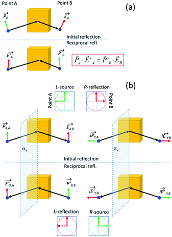
In the section below we present an intuitive, geometrical argument for deviation from reciprocity in the reflection of chiral materials. First, we formulate the principle of reciprocity in electromagnetism, also known as Lorentz reciprocity, more precisely.17,33,34 Here one considers two dipole sources; ![[P with combining right harpoon above (vector)]](https://www.rsc.org/images/entities/i_char_0050_20d1.gif) located at point A and
located at point A and  at B, see Fig. 4a. Both
 ![[P with combining right harpoon above (vector)]](https://www.rsc.org/images/entities/i_char_0050_20d1.gif) and
and  radiate resulting in, respectively, the radiation fields
 ![[E with combining right harpoon above (vector)]](https://www.rsc.org/images/entities/i_char_0045_20d1.gif) and
and  . The Lorentz reciprocity theorem then holds that the component of
  at point A in the direction of
 ![[P with combining right harpoon above (vector)]](https://www.rsc.org/images/entities/i_char_0050_20d1.gif) equals to the component of
equals to the component of ![[E with combining right harpoon above (vector)]](https://www.rsc.org/images/entities/i_char_0045_20d1.gif) at point B in the direction
at point B in the direction  , in short:
 ![[P with combining right harpoon above (vector)]](https://www.rsc.org/images/entities/i_char_0050_20d1.gif) A·
A· =
=  ·
·![[E with combining right harpoon above (vector)]](https://www.rsc.org/images/entities/i_char_0045_20d1.gif) B.
B.
Reciprocity can be related to symmetry.35 To illustrate this, we place a vertical symmetry plane between the source and the detector, see Fig. 4b. Given the mirror symmetry, we can now decompose sources and fields into symmetric and antisymmetric components. First, we look at a symmetric, vertically oriented dipole and the associated vertically polarized radiation field, see Fig. 4b, right. If we now take the mirror image of both the source and the field, we arrive at the reciprocal reflection. Using a similar symmetry argument, also the reciprocity for the antisymmetric horizontal components can be established. We note that upon reflection, the s and p components experience a different geometric phase shift. Now by combining a dipole oscillator in the x-direction with an oscillator in the y-direction with a 90° phase difference, we get a source for circularly polarized light. The left polarized source produces a right polarized reflected wave if the refection amplitudes for s and p are equal as would be expected for an isotropic material under normal incidence. Considering now also the corresponding mirror imaged reflection process, one predicts IRL = ILR so that reciprocity is obeyed also for the circular polarization. Yet, this reciprocity is predicated on the presence of the mirror image symmetry and is thus no longer ensured for chiral materials that lack the mirror plane. As mentioned above, experiments on the reflection of light by cholesteric films indeed indicate deviation from reciprocity in their polarization inverting reflection.
Strong coupling between circularly polarized light and chiral matter
In the sections above we have considered the traditional approach for the manipulation of molecules with circularly polarized light. Here illumination with a circularly polarized light leads to a difference in the population of the excited states of two enantiomeric forms of a chiral molecule. Recent advances in experimental studies of the interaction between light and matter have shown that under specific conditions, the coupling between light and matter can become so strong that the energies of the excited states of molecules can be changed significantly through interaction with light.36 If dye molecules are placed in a resonant optical cavity, the conversion of a photon into an exciton and vice versa can become such frequent and coherent processes that the quantum states for the photon and the exciton hybridize to form a new quasi-particle called polariton.37–39 The polariton formation strongly depends on the quality of the optical cavity. Highly reflective, perfectly aligned mirrors lead to better confinement of the photon that is then forced to interact very often with the material in the cavity.Notably when putting molecules in resonant cavities, even the zero-point fluctuations of the electromagnetic fields in the cavity that are present in the absence of any illumination, can cause a significant shift of excited state energies.40 By tuning cavity resonances to molecular vibrational absorption bands the reactivity of molecules under dark conditions can be altered.41
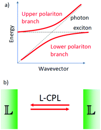
We may now imagine an optical cavity with left-handed cholesteric mirrors, see Fig. 5. Such a cavity would support only left circularly polarized waves, provided that the wavelength of the resonant cavity modes and the wavelength of selective reflection by the mirrors are carefully tuned. Although perhaps not impossible, building such a cavity is technically highly challenging. The presence of molecules or molecular materials with dipole allowed transitions at frequencies near the cavity resonance may now induce the formation of chiral polaritons. If the molecular material is chiral, there may now be a difference in the excited state energy for the two mirror-image related forms. This chiral discrimination could potentially alter the reaction rates such that chiral products with a net enantiomeric excess can be obtained from achiral precursors. The chiral cavity might also lead to chiral symmetry breaking in nematic liquid crystals favoring cholesteric order of one particular handedness.42
Coupling the spin and orbital angular momentum of light.
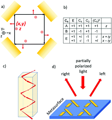
If we confine light to a small space, it can reveal new optical phenomena which are not observable for extended plane waves. As an example, we mention the Goos–Hänchen and Fedorov–Imbert shifts, both referring to displacements of the center of an optical beam upon reflection away from the path predicted by geometrical optics.43 When light is focused, it acquires some longitudinal polarization components. Furthermore, if the phase front of the focused wave is manipulated such that it is no longer constant across the beam, the light can acquire an additional angular momentum, also known as orbital angular momentum.44 Circularly polarized photons in a regular, plane wave can only have two values for the spin quantum number: +1 ħ and −1 ħ. In a focused light beam with an angular momentum, the photon can also occupy states with quantum number for the angular momentum other than +1 ħ or −1 ħ. For confined light also a coupling between the spin and orbital angular momentum is possible. Now for these confined beams, the spin state of the photon may affect the orbital path the photon choses to follow through a coupling of the spin and orbital components of the angular momentum. This photon spin–orbit coupling can lead to the so-called optical spin Hall effect in analogy to the spin hall effect for spin polarized electrons.45–47 The optical magnus effect48 and Feodorov–Imbert shift33,49 are closely related phenomena.50 In later sections we will explore the analogy between photon spin and electron spin in more detail. In this section we illustrate the spin–orbit coupling for the photon with a simple elementary example.Suppose we take a flat (partially) reflecting surface of a material. Then by taking four exact copies of this reflecting surface, we can bend the path of a light beam, see Fig. 6. Here the reflection under 45° incidence is repeated three times resulting in a light path that is either square planar if the momentum of the ray in the z direction is zero or helicoidal if there is a finite momentum along the vertical. The polarization of the incident and the four times reflected rays can now be analyzed using the same reference frame. For every possible polarization state of the departing beam, the closed optical trajectory now yields a polarization for the returning beam. The Poincare sphere of all possible polarizations for the incoming beam is mapped onto the Poincare sphere for returning polarizations. Then, according to the Brouwer fixed point theorem, there should always be at least one polarization which is mapped onto itself. We refer to such an invariant polarization as an eigen polarization. To find the eigenpolarizations we make use of the fourfold rotational symmetry of the problem. According to the group table for the C4 point group, there are two eigenpolarizations, one parallel to z and the other in the x, y plane corresponding to s and p polarized light. Note that the p polarization acquires a net 360° degree geometrical phase shift while the s wave retains the same phase upon completing a full round trip. A sufficient condition for the existence of such a closed optical trajectory is the presence of a horizontal mirror (x, y) symmetry plane. If we now however take the reflecting material to be chiral, the reflection will mix the s and p components of the incoming light. As a result, a perfectly square planar reflection geometry is no longer allowed, and the light must follow a helicoidal path, see Fig. 6c. This staircase like trajectory now has macroscopic helicity. The chirality of the material dictates both the macroscopic helicity as well as the circular polarization component. The orbital and spin angular momenta have become coupled.
The optical spin Hall effect allows for new optical components that can separate the circular polarization components of an unpolarized or a partially polarized incoming beam, see Fig. 6d. Here it has been shown that surfaces decorated with metal nanostructures in a two dimensional (2-D) chiral pattern can deflect the left and right circular components of an incoming beam in different directions.51 We note that the reflecting surface with its 2-D chiral pattern is in fact a 3-D chiral object.
Steering a photoexcitation with circular polarization
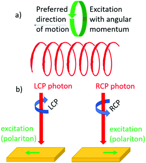
Chirality can influence the direction of motion of objects. We recall the screw for which rotational and translational motion are coupled. Similarly, one might expect that upon creating an electronic excitation with angular momentum in a chiral material, the particle will move preferentially in a particular direction set by the helicity of the material, see Fig. 7a. Such an effect has indeed been confirmed in recent decades.52–54 Here the angular momentum of circularly polarized light is used to create quasi-particles in a material with a particular spin polarization. Depending then on whether left or right circularly polarized light is used, the particle will move either up or down, see Fig. 7b. This effect is closely related to the optical spin Hall effect discussed in the preceding section. The effect is not exclusive to chiral materials but can also be observed in achiral materials provided that the geometry of the optical experiment itself is chiral.55Interesting from an application perspective is that the effect occurs in systems where helicity can be engineered such as metamaterials56,57 and bilayer graphene58–60 and may allow for new and unconventional optical elements for manipulating the polarization of light.61
Chiral particles other than the photon to probe chirality?
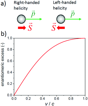
So far, we have seen that circularly polarized light with its chiral photons is a useful and convenient tool to probe the handedness of materials. Are there any other (elementary) particles that may be used to sense the (a)chirality of molecules or condensed matter? In principle any particle with spin might do. Consider for instance the electron: an electron with spin aligned parallel to its direction of motion has right-handed helicity while an electron with spin and momentum in opposite directions has left-handed helicity. A moving electron has a handedness and its transport may be affected by the chirality of the materials through which it is moving.There is however a catch. While a photon has zero rest mass and will travel at the speed of light for any observer, the electron has a finite rest mass and different observers may not agree on the direction and magnitude of the velocity of a moving electron. As a result, the two observers may assign opposite helicities to a moving electron. Helicity is not Lorentz invariant, even though helicity is a constant of motion. In contrast, a particle moving at the speed of light has the same helicity for every observer. The helicity of a photon is absolute and describes its chirality. A moving electron obeys the Dirac equation and is described by a Dirac spinor, a wave with four components. When analyzed in more detail, the Dirac spinor always combines a solution having left-handed chirality with a solution of right-handed chirality. The chirality of these two contributions, also known as Weyl spinors, is Lorentz invariant. An electron at rest is a perfect 50–50% mixture of two enantiomeric forms. For a moving electron with say positive helicity, the left-handed component has a higher weight that the right-handed one.
For the electron, chirality is not a constant of motion. At a deeper level it has been argued that an electron is subject to ‘Zitterbewegung’ and oscillates very rapidly between a left-handed form and a right-handed form.62–64 The associated chiral oscillation frequency for a slow electron is predicted to be very high: νch = 2 mec2/h = 2 × 10²⁰ s. The chiral oscillation frequency may be related to a wavelength via λ = c/νch, i.e. half the Compton wavelength λC = h/mec = 2.4 pm. λC/2 may be interpreted as the length over which a slow electron keeps the same chirality. For electrons moving at a higher speed, oscillation frequency will appear reduced (time dilation) and the electron will retain the same chirality over a longer distance. We note that other elementary particles show similar oscillations in chirality. The chiral oscillations of the neutrino have been confirmed experimentally.65
Wavefunctions should be interpreted in terms of probability according to the Copenhagen interpretation of quantum mechanics. Also the Dirac spinor describing the rapid chirality oscillations can be interpreted probabilistically as representing the chance to find the electron in its left or right chiral form. Thus in a sense, the Dirac spinor describes the enantiomeric excess of an electron. The absolute magnitude of the enantiomeric excess of an electron in a certain helicity state depends on its speed, see Fig. 8b. An electron at rest is a racemic mixture, while an individual electron moving at a speed very close to the speed of light has a very high enantiomeric purity approaching that of a circularly polarized photon.
So, in summary also massive particles such as electrons have a handedness, yet only at relativistic speeds will the spin states for an electron feature the persistent chirality that is characteristic of and unique to that of the photon. From an experimental point of view, one would thus expect that moving electrons with longitudinal spin polarization would interact differently with left and right circularly polarized light, i.e. electrons with preferred helicity should show optical activity. Such an experiment has recently indeed been proposed66 but as far as we know has not been carried out yet. Incidentally, the above analysis also makes clear that for electromagnetic waves travelling at less than the speed of light in vacuum, for instance visible light travelling though glass, the circular polarization cannot be as perfect as for the photon in vacuum.
Chiral molecules in the gas phase indeed show different cross sections for scattering of electrons with left- and right-handed helicity.67 Experimental studies pioneered by Farago68 on various molecules69–73 have shown asymmetries of the order of 10−3 or less and have indicated the importance of heavy atoms in the chiral molecules. The asymmetry roughly scales as Z2 with Z as the atomic number of the heaviest element in the molecules. The dependence on Z supports the notion that relativistic effects are important. Also the interaction of chiral molecules with the antiparticle of the electron, or positron, has been investigated.74,75 Radioactive decay can yield electrons or positrons of essentially one helicity and experimental evidence has been put forward that these ‘naturally’ spin-polarized positrons or electrons can induce asymmetric synthesis.76
In the past decade, attention has shifted from chiral molecules in the gas phase to chiral semiconducting materials. Selectivity in transport of electrons with left or right-handed helicity has become an area of very active research.77–79 It has been reported that a layer of chiral organic molecules acts as an effective spin filter for electrons when current is passed through the layer.80,81 The effect is referred to as chiral induced spin selectivity (CISS). Selectivities exceeding 85% for left vs right helical electrons have been reported.82 Qualitatively the spin selectivity in the transport of spin polarized electrons is understandable in terms of the chirality of a moving electron. Quantitatively, however, the reported CISS effects pose an interesting puzzle. For the low energy transport measurements involving molecular materials with only light atoms, one does not expect that the speed v of the electrons approaches relativistic values, so v/c < 0.1. The relatively low speeds imply only a modest enantiomeric excess of the electrons: e.e. < 20%, see Fig. 8b. Supposing that the chiral material will discriminate based primarily on the chirality and enantiomeric excess of the electron, then one might wonder: how can the selectivity of the chiral material for one of the spin polarizations of the electrons can be so high, in some cases exceeding 80%?
The CISS effect has also been reported for materials with heavy atoms, e.g. lead halide based perovskites.83 Here the relativistic behavior of the electron and the associated strong spin–orbit coupling are more pronounced than in the case of lighter, carbon based materials.
The chiral induced spin selectivity discussed above does, in principle, not require a magnetic field, although in practice magnetic materials are used to polarize the spins of the electrons. In the presence of static magnetic fields, the chirality of a material can influence electrical transport. This is known as electrical magnetochiral anisotropy.84,85 Here the electrical resistance of the material shows a dependence on the strength of the magnetic field. Next to the normal magnetoresistance that varies quadratically with the strength of the magnetic field, chiral materials can feature a contribution that is linear to the strength of the magnetic field with a sign that depends on the handedness of the substance. While the first studies focused on metallic wires with macroscopic helicity, later studies have found evidence for the effect in chiral carbon nanotubes.86
Also an inverse magneto chiral anisotropy effect has been investigated. Here the transport of an electric charge through a chiral material conductor induces a magnetic field that is either parallel or antiparallel to the direction of the current depending on the chirality of the material.87 Recently experimental evidence for the genesis of such a magnetic field has been reported for electrical current through single crystals of the non-magnetic elemental semiconductor tellurium with the chiral, trigonal crystal structure.88
The electrical magnetochiral anisotropy and the CISS effect are described by axial tensors with probably the same symmetry properties.89 For the effects to be non-zero in the isotropic average a necessary and sufficient condition may be chirality.90 Yet in the anisotropic condensed phase, the effects may not be exclusively limited to chiral systems and might even show up in systems with higher symmetry for specific orientations in a way similar to optical activity as discussed above.
Steering an electron: the circular photogalvanic effect
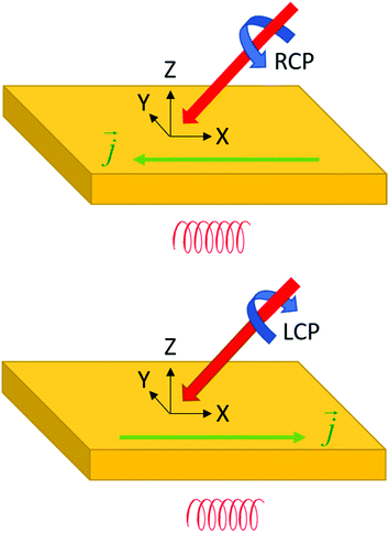
In the previous sections we have discussed the handedness of materials, photons and electrons. We are now at a stage where we explore how these three different types of helicities can interact. Using circularly polarized light and making use of chirality (either in the material or in the wider geometry of the experiment) it has also proven to be possible to control the direction in which photogenerated charge carriers move.91–93 This is known as the circular photogalvanic effect.94,95 Illumination of a chiral material with left or right circularly polarized light at an appropriate angle of incidence, results in a net photocurrent either in the forward or reverse lateral direction depending on the circular polarization of the incident light, see Fig. 9. The effect is analogous to the photonic spin hall effect discussed in the previous section. The circular galvanic effect may be understood qualitatively in terms of strong spin orbit coupling96–98 of photogenerated carriers in a non-centrosymmetric material.99Chirality and time
Chirality was introduced as primarily a purely geometrical property of objects in three-dimensional space. Yet when trying to probe chirality in molecules and molecular materials, one involuntarily introduces time as an additional parameter. Furthermore, according to special relativity, time should in many respects be treated on a similar footing as the other three spatial coordinates. This indicates that chirality might be regarded as part of an extended concept associated with handedness in four-dimensional Minkowski space.100 Assuming that objects, and more general processes, are either symmetric or antisymmetric under space inversion (parity, P) and time inversion (T), we can draw up a character table showing all the possible characters, see Table 1.| V | I | P | T | PT | ||||
|---|---|---|---|---|---|---|---|---|
| a | +1 | +1 | +1 | +1 | ‘Symm.’ | Rod |
![[E with combining right harpoon above (vector)]](https://www.rsc.org/images/entities/i_char_0045_20d1.gif) · ·![[E with combining right harpoon above (vector)]](https://www.rsc.org/images/entities/i_char_0045_20d1.gif) , , ![[B with combining right harpoon above (vector)]](https://www.rsc.org/images/entities/i_char_0042_20d1.gif) · ·![[B with combining right harpoon above (vector)]](https://www.rsc.org/images/entities/i_char_0042_20d1.gif) |
N |
| c | +1 | −1 | +1 | −1 | ‘Space odd’ | Screw |
![[E with combining right harpoon above (vector)]](https://www.rsc.org/images/entities/i_char_0045_20d1.gif)
|
n L–nR |
| b | +1 | +1 | −1 | −1 | ‘Time odd’ | Rot. |
![[B with combining right harpoon above (vector)]](https://www.rsc.org/images/entities/i_char_0042_20d1.gif)
|
κ |
| e | +1 | −1 | −1 | +1 | ‘PT symm.’ | Transl. |
![[E with combining right harpoon above (vector)]](https://www.rsc.org/images/entities/i_char_0045_20d1.gif) · ·![[B with combining right harpoon above (vector)]](https://www.rsc.org/images/entities/i_char_0042_20d1.gif) , , ![[B with combining right harpoon above (vector)]](https://www.rsc.org/images/entities/i_char_0042_20d1.gif) , , ![[E with combining right harpoon above (vector)]](https://www.rsc.org/images/entities/i_char_0045_20d1.gif) × × ![[B with combining right harpoon above (vector)]](https://www.rsc.org/images/entities/i_char_0042_20d1.gif) |
κ L–κR |
Static objects are time invariant and must have character +1 under T and so, looking at Table 1, static objects transform according to the representation a or c. A circularly polarized photon is a combination of rotational motion (spin, (b)) and translational motion (momentum (e)) and transforms as b × e = c.
The group table for the Klein-four group can be used to classify chiroptical phenomena in four dimensions. To see how this works we first consider the time-domain response function G(t) for a material, i.e. the response of a substance to a sharply peaked, delta function-like perturbation at t = 0. We assume the response to be linear in the perturbation. The principle of causality demands that a material does not respond before it is perturbed (‘the system does not squeak before it is squeezed’) and thus requires G(t) = 0 for t < 0. The time domain response function can then be expressed as the sum of a time-even part and a time-odd part with Geven(t) = (G(|t|) + G(|−t|))/2 and Godd(t) = (G(|t|) − G(|−t|))/2, see Fig. 10. By means of Fourier transformation the time-domain response function G(t) can be converted to the frequency domain. The frequency domain response function will in general be complex: ñ(ω) = n(ω) + ik(ω), with the real part n(w) deriving from the time-even response Geven(t) and the imaginary part ik(ω) from the time-odd part of the linear response of a material to a pulse of light. Now because n(ω) and κ(ω) contain essentially the same information, i.e. the non-zero time domain response G(t) with t > 0, they must be related. It can be shown, with relatively little effort,101 that this relation involves an integral transformation known as the Kramers–Kronig transform or the closely related Hilbert transform. We note that the time-odd part of the response is related to dissipation of energy and corresponds to absorption of light. When absorbing light, the system is out-of-equilibrium and assumed to adopt a stationary state.
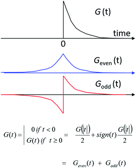 | ||
| Fig. 10 A time-domain, linear response function G(t) should obey causality and can be decomposed into a time-even component and a time-odd component. | ||
The linear optical response of an isotropic, achiral material can thus be characterized by a complex refractive index containing as real part n(ω) the time-even or elastic part of the response in combination with an absorption index κ(ω) covering the time-odd or dissipative part of the response. Looking at the character table of the Klein group, we find that n transforms according to the irreducible representation a, while the absorption κ transforms as b. For a chiral isotropic material, it then follows that the circular differential refractive index nL − nR expressing the optical rotation of the plane of polarization of linearly polarized light transforms as c, i.e. the product of the symmetry character for the chiral material (c) and the character for the refractive index (a). For the circular differential absorption we get symmetry character e (= c × b).
Using the character table for the four-group one can now systematically search for ‘new’ phenomena specific to chiral materials. For instance, if a chiral material shows selectivity in the inelastic transport of electrons with opposite helicity, then one might also expect a rotation of the plane of transverse spin polarization for electrons when passing through a layer of chiral material. Polarimetry for electrons,102 positrons, protons103 or neutrons104 is known but so far, no report on the rotation of the polarization by chiral compounds seems to have appeared. As a second example, we note that the resistive and capacitive response of a material to an alternating electric field corresponds to respectively the time-odd and time-even part of the response to the applied electric field. Now if the electrical resistance of a substance shows electrical magnetochiral anisotropy as discussed above, one should also expect a corresponding magnetochiral capacitive effect. The latter effect would involve the influence of a magnetic field on the electrical polarizability of a chiral material. Such a magnetoelectric effect involving coupling between magnetization and electrical polarization has recently indeed been reported for chiral materials.105,106
The character table for the Klein group is also useful when looking for methods to induce enantioselectivity in the synthesis of molecules and materials. A chiral, molecular reaction product in the static, chiral environment provided by e.g. resolved cyclodextrin molecules leads to a time-invariant diastereomeric energy difference for the two mirror image related forms of the reactant in the host: c × c = a. A chemical reaction resulting in the formation of the chiral product under thermodynamic control can now yield a net enantiomeric access of one of the mirror image related forms. This corresponds to the ‘true’ chiral influence by the cyclodextrin as discussed by Barron.107,108 In contrast, a reaction under a ‘false’ chiral influence such as exerted by e.g. static collinear magnetic and electric field (symmetry character e) symmetry only yields a net enantiomeric excess if the reaction is carried out under kinetic control because the time reversed reaction will favor the opposite product (c × e = b).
‘False’ chirality is highly relevant for modern materials science. Here one of the major challenges is the development of magnetoelectric multiferroic materials, i.e. materials that can be magnetized by application of an electric field and electrically polarized by a magnetic field.109–111 This magneto-electric coupling is described by the same tensor that governs the optical activity discussed earlier. Yet while optical activity is a response to alternating electromagnetic waves, the magneto-electric effect describes the effect of static electric and magnetic fields. The magneto-electric effect is a static property of a material under equilibrium conditions and thus time-invariant (+1 under T).112 Yet the polarization and magnetization that are related by the tensor elements describing the effect have opposite symmetries under time inversion. Therefore, the magneto-electric effect can only occur in materials with a broken time symmetry. The presence of permanent magnetic dipoles in a material, viz. unpaired electrons, suffices to meet this requirement. Furthermore, polarization and magnetization also have opposite spatial inversion symmetry and so the effect only occurs in materials lacking inversion symmetry. Chiral materials satisfy this second requirement but also materials that are ‘falsely’ chiral do. A material will be falsely chiral if it has a nuclear geometry and electron density distribution that is achiral and if it is not superimposable on its mirror image via spatial symmetry operations because of the opposite orientation of magnetic moments on sites related via symmetry operations but does convert to its enantiomeric form under time inversion operation. The magnetic point group of the material should not contain inversion as a symmetry element.
Unidirectional motion in molecular machines and chirality
In the previous section we have explored the connection between chirality and time. A further illustration of this connection is the possibility to control the directionality of molecular motion through the chirality of the molecules involved. This brings us to the field of molecular machines.In one of his many illuminating lectures, Feynman considered a machine that can convert random thermal molecular movements into unidirectional rotational motion that may do useful work; the well-known ratchet and pawl machine, see Fig. 11. As can be seen, Feynman's machine is chiral and will work when placed in a temperature gradient. Collisions of molecules with the turbine blades on the high temperature side will set the axle in a unidirectional rotational motion and a small weight may be lifted. The machine is able to do useful work as long as the temperature on the ratchet side is lower than that on the turbine side. If such a temperature difference is present, high energy molecular collisions on the turbine side powering the rotation are more likely than molecular collision on the ratchet side that may temporarily relieve the pawl, causing the rope to unwind again. If the temperature gradient is not maintained externally, eventually frictional motion on the side of the pawl and loss of kinetic energy of the molecules on the turbine side will cause a gradually equilibration of the temperatures on the two sides causing the machine to stop turning. Thus, effectively, the machine is able to deliver work because of the flow of heat from a higher to lower temperature. Using now the symmetry analysis discussed in the previous section, the flow of heat (symmetry character e) in combination with the structural chirality of the machine (c) results in unidirectional rotation (b) because e × c = b.
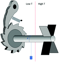 | ||
| Fig. 11 Ratchet and pawl machine as considered by Feynman.113 | ||
The use of chirality114–116 to control the direction of rotational motion in molecular machines is, now, well established.117–120 The question is whether 3D chirality is needed or whether just chirality in two dimensions suffices to achieve unidirectionality.121 Interesting directions in this lively research field concern the possible dependence of the mechanical viscoelastic response of chiral materials on the direction of twist motion.122 For a macroscopic twined rope one indeed expects a different mechanical response for the clockwise and anticlockwise twisting of the rope. For molecular systems one might also expect such a directional dependence, provided that the material shows helicity on a length scale similar to that of the mechanical experiment. Finally, can the direction of rotation in molecular system be controlled directly by the circular polarization of the light that is used to drive the motion? Materials with chiral nematic ordering and photoisomerizable groups indicate that the circular polarization of the illumination has an effect on the initial direction of motion. Yet no continuous rotation under illumination has been accomplished; to complete one full period also a thermal step has to be included next to the illumination stages.123
Conclusions
Introducing chirality in a molecule or material is a sure way to engineer a combined responsivity to perturbations of different spatial symmetry types or to provoke a response to a perturbation of an opposite spatial symmetry. In this review we have mainly focussed on electric and magnetic fields with optical activity as a key example of a joint responsivity to alternating electric and magnetic fields. In chiral materials, electrons are forced to move along a helical path by internal organization. This introduces a coupling between electrical polarization and magnetization, facilitating new types of functionality. Chirality refers primarily to spatial symmetry. Yet as a tool to understand the response dynamics of materials it is most effective when considered together with time-based symmetries.Conflicts of interest
There are no conflicts to declare.Notes and references
- H. D. Flack, Helv. Chim. Acta, 2003, 86, 905 CrossRef CAS
.
- M. Nespolo, M. Aroyo and B. Souvignier, J. Appl. Crystallogr., 2018, 51, 1481 CrossRef CAS
.
- W. R. Morgan and D. E. Leyden, J. Am. Chem. Soc., 1970, 92, 4527 CrossRef CAS
.
- H. Marom, P. U. Biedermann and I. Agranat, Chirality, 2007, 19, 59 CrossRef PubMed
.
- A. B. Buda and K. Mislow, J. Am. Chem. Soc., 1992, 114, 6006 CrossRef CAS
.
- M. A. Osipov, B. T. Pickup and D. A. Dunmur, Mol. Phys., 1995, 84, 1193 CrossRef CAS
.
- H. Zabrodsky, S. Peleg and D. Avnir, J. Am. Chem. Soc., 1992, 114, 7843 CrossRef CAS
.
- M. Petitjean, Entropy, 2003, 5, 271 CrossRef CAS
.
- J. J. Pelayo, R. L. Whetten and I. L. Garzón, J. Phys. Chem. C, 2015, 119, 28666 CrossRef CAS
.
- A. Nemati, S. Shadpour, L. Querciagrossa, L. Li, T. Mori, M. Gao, C. Zannoni and T. Hegmann, Nat. Commun., 2018, 9, 3908 CrossRef PubMed
.
- J. K. O’Loane, Chem. Rev., 1980, 80, 41 CrossRef
.
- S. C. J. Meskers, ChemPhotoChem, 2022, 6, e202100154 CrossRef CAS
.
- P. C. Sercel, Z. V. Vardeny and A. L. Efros, Nanoscale, 2020, 12, 18067 RSC
.
- G. Long, R. Sabatini, M. I. Saidaminov, G. Lakhwani, A. Rasmita, X. Liu, E. H. Sargent and W. Gao, Nat. Rev. Mater., 2020, 5, 423 CrossRef
.
-
J. F. Nye
The physical properties of crystals, Clarendon Press, Oxford, 1985 Search PubMed
.
-
P. G. De
Gennes, The physics of liquid crystals, Clarendon Press, Oxford, 1974 Search PubMed
.
- R. Ozaki, S. Hashimura, S. Yudate, K. Kadowaki, H. Yoshida and M. Ozaki, OSA Continuum, 2019, 2, 3554 CrossRef CAS
.
- W. D. St. John, W. J. Fritz, Z. J. Lu and D.-K. Yang, Phys. Rev. E: Stat. Phys., Plasmas, Fluids, Relat. Interdiscip. Top., 1995, 51, 1191 CrossRef CAS PubMed
.
- Y. Mohri, J. Kobashi, H. Yoshida and M. Ozaki, Adv. Opt. Mater., 2017, 5, 1601071 CrossRef
.
- P. Saha and V. A. Davis, ACS Appl. Nano Mater., 2018, 1, 2175 CrossRef CAS
.
- J. Kobashi, H. Yoshida and M. Ozaki, Nat. Photonics, 2016, 10, 389 CrossRef CAS
.
- B. Frka-Petesic, G. Guidetti, G. Kamita and S. Vignolini, Adv. Mater., 2017, 29, 1701469 CrossRef PubMed
.
- J. H. Park, J. Noh, C. Schütz, G. Salazar-Alvarez, G. Scalia, L. Bergström and J. P. F. Lagerwall, Chem. Phys. Chem., 2014, 15, 1477 CrossRef CAS PubMed
.
- G. Lakhwani and S. C. J. Meskers, J. Phys. Chem. Lett., 2011, 2, 497 Search PubMed
.
- C. Kulkarni, D. Di Nuzzo, E. W. Meijer and S. C. J. Meskers, J. Phys. Chem. B, 2017, 121, 11520 CrossRef CAS PubMed
.
- R. J. Potton, Rep. Prog. Phys., 2004, 67, 717 CrossRef
.
- Y. Tokura and N. Nagaosa, Nat. Commun., 2018, 9, 3740 CrossRef PubMed
.
- C. Caloz, A. Alù, S. Tretyakov, D. Sounas, K. Achouri and Z.-L. Deck-Léger, Phys. Rev. A, 2018, 10, 047001 CAS
.
- H. Y. Xie, P. T. Leung and D. P. Tsai, J. Math. Phys., 2009, 50, 072901 CrossRef
.
- J. A. Kong, Proc. IEEE, 1972, 60, 1036 Search PubMed
.
- M. Mansuripur and D. P. Tsai, Opt. Commun., 2011, 284, 707 CrossRef CAS
.
- P. J. Bennett, S. Dhanjal, Y. P. Svirko and N. I. Zheludev, Opt. Lett., 1996, 21, 1955 CrossRef CAS PubMed
.
- A. T. De Hoop, Appl. Sci. Res., Sect. B, 1959, 8, 135 CrossRef
.
- A. Drezet and C. Genethttp://arxiv.org/abs/1704.02185v1.
- P. T. Leung and R. Chang, J. Opt. A: Pure Appl. Opt., 2008, 10, 075201 CrossRef
.
- F. J. Garcia-Vidal, C. Ciuti and T. W. Ebbesen, Science, 2021, 373, 0336 CrossRef PubMed
.
- J. J. Hopfield, Phys. Rev., 1958, 112, 1555 CrossRef CAS
.
- S. I. Pekar, J. Phys. Chem. Solids, 1958, 5, 1 CrossRef
.
- D. L. Mills and E. Burstein, Rep. Prog. Phys., 1974, 37, 817 CrossRef CAS
.
- R. Stanley, R. Houdré and C. Weisbuch, Phys. Rev. B: Condens. Matter Mater. Phys., 1996, 53, 10995 CrossRef CAS PubMed
.
- A. Thomas, L. Lethuillier-Karl, K. Nagarajan, R. M. A. Vergauwe, J. George, T. Chervy, A. Shalabney, E. Devaux, C. Genet, J. Moran and T. W. Ebbesen, Science, 2019, 209(363), 615 CrossRef PubMed
.
- T. Sekine, T. Niori, J. Watanabe, T. Furukawa, S. W. Choi and H. Takezoe, J. Mater. Chem., 1997, 7, 1307 RSC
.
- K. Y. Bliokh and A. Aiello, J. Opt., 2013, 15, 014001 CrossRef
.
- M. W. Beijersbergen, R. P. C. Coerwinkel, M. Kristensen and J. P. Woerdman, Opt. Commun., 1994, 112, 321 CrossRef CAS
.
- A. V. Kavokin, G. Malpuech and M. M. Glazov, Phys. Rev. Lett., 2005, 95, 136601 CrossRef PubMed
.
- M. Onoda, S. Murakami and N. Nagaosa, Phys. Rev. Lett., 2004, 93, 083901 CrossRef PubMed
.
- C. Leyder, M. Romanelli, J. P. Karr, E. Giacobino, T. C. H. Liew, M. M. Glazov, A. V. Kavokin, G. Malpuech and A. Bramati, Nat. Phys., 2007, 3, 628 Search PubMed
.
- A. V. Dooghin, N. D. Kundikova, V. S. Liberman and B. Ya Zel’dovich, Phys. Rev. A: At., Mol., Opt. Phys., 1992, 45, 8204 CrossRef PubMed
.
- F. Pillon, H. Gilles and S. Girard, Appl. Opt., 2004, 43, 1863 CrossRef PubMed
.
- K. Y. Bliokh and Y. P. Bliokh, Phys. Rev. Lett., 2006, 96, 073903 CrossRef PubMed
.
- A. Pors, M. G. Nielsen and S. I. Bozhevolnyi, Optica, 2015, 2, 716 CrossRef CAS
.
- A. V. Kavokin, G. Malpuech and M. M. Glazov, Phys. Rev. Lett., 2005, 95, 136601 CrossRef PubMed
.
- C. Leyder, M. Romanelli, J. P. Karr, E. Giacobino, T. C. H. Liew, M. M. Glazov, A. V. Kavokin, G. Malpuech and A. Bramati, Nat. Phys., 2007, 3, 628 Search PubMed
.
- J. Lin, J. P. B. Mueller, Q. Wang, G. Yuan, N. Antoniou, X.-C. Yuan and F. Capasso, Science, 2013, 340, 331 CrossRef CAS PubMed
.
- O. Hosten and P. Kwiat, Science, 2008, 319, 787 CrossRef CAS PubMed
.
- P. Lodahl, S. Mahmoodian, S. Stobbe, A. Rauschenbeutel, P. Schneeweiss, J. Volz, H. Pichler and P. Zoller, Nature, 2017, 541, 473 CrossRef CAS PubMed
.
- Y. Liu, Y. Ke, H. Luo and S. Wen, Nanophotonics, 2017, 6, 51 CAS
.
- W. J. M. Kort-Kamp, F. J. Culchac, R. B. Capaz and F. A. Pinheiro, Phys. Rev. B, 2018, 98, 195431 CrossRef CAS
.
- Z. Chen, H. Yang, Y. Xiao, J. Pan, Y. Xia and W. Zhu, J. Opt. Soc. Am. A, 2021, 38, 1232 CrossRef PubMed
.
- X. Zhang, Y. Zhong, T. Low, H. Chen and X. Lin, Phys. Rev. B, 2021, 103, 195405 CrossRef CAS
.
- A. Pors, M. G. Nielsen and S. I. Bozhevolnyi, Optica, 2015, 2, 716 CrossRef CAS
.
-
R. Penrose, The road to reality, Jonathan Cape, London, 2004 Search PubMed
.
- V. A. S. V. Bittencourt, A. E. Bernardini and M. Blasone, Eur. Phys. J. C, 2021, 81, 411 CrossRef CAS
.
- D. Hestenes, Found. Phys., 1990, 20, 1213 CrossRef
.
- https://www.nobelprize.org/prizes/physics/2015/press-release/ .
- D. B. Melrose and J. I. Weise, Phys. Rev. E: Stat. Phys., Plasmas, Fluids, Relat. Interdiscip. Top., 2003, 68, 046404 CrossRef CAS PubMed
.
- D. M. Campbell and P. S. Farago, Nature, 1985, 318, 52 CrossRef CAS
.
- P. S. Farago, J. Phys. B, 1981, 14, L743 CrossRef CAS
.
- S. Mayer and J. Kessler, Phys. Rev. Lett., 1995, 74, 4803 CrossRef CAS PubMed
.
- C. Nolting, S. Mayer and J. Kessler, J. Phys. B, 1997, 30, 5491 CrossRef CAS
.
- K. Blum and D. G. Thompson, Adv. At., Mol., Opt. Phys., 1998, 38, 39 Search PubMed
.
- J. M. Dreiling, F. W. Lewis, J. D. Mills and T. J. Gay, Phys. Rev. Lett., 2016, 116, 093201 CrossRef CAS PubMed
.
- J. M. Dreiling, F. W. Lewis and T. J. Gay, J. Phys. B, 2018, 51, 21LT01 CrossRef
.
- D. W. Gidley, A. Rich, J. Van House and P. W. Zitzewitz, Nature, 1982, 297, 639 CrossRef CAS PubMed
.
- L. Chiari, A. Zecca, S. Girardi, A. Defant, F. Wang, X. G. Ma, M. V. Perkins and M. J. Brunger, Phys. Rev. A: At., Mol., Opt. Phys., 2012, 85, 052711 CrossRef
.
- S. Mahurin, M. McGinnis, J. S. Bogard, L. D. Hulett, R. M. Pagni and R. N. Compton, Chirality, 2001, 13, 636 CrossRef CAS PubMed
.
- S.-H. Yang, R. Naaman, Y. Paltiel and S. S. P. Parkin, Nat. Rev. Phys., 2021, 3, 328 CrossRef
.
- R. Naaman, Y. Paltiel and D. H. Waldeck, Nat. Rev. Chem., 2019, 3, 250 CrossRef CAS
.
- M. Kettner, V. V. Maslyuk, D. Nürenberg, J. Seibel, R. Gutierrez, G. Cuniberti, K.-H. Ernst and H. Zacharias, J. Phys. Chem.
Lett., 2018, 9, 2025 CrossRef CAS PubMed
.
- K. Ray, S. P. Ananthavel, D. H. Waldeck and R. Naaman, Science, 1999, 283, 814 CrossRef CAS PubMed
.
- B. Göhler, V. Hamelbeck, T. Z. Markus, M. Kettner, G. F. Hanne, Z. Vager, R. Naaman and H. Zacharias, Science, 2011, 331, 894 CrossRef PubMed
.
- C. Kulkarni, A. K. Mondal, T. K. Das, G. Grinbom, F. Tassinari, M. F. J. Mabesoone, E. W. Meijer and R. Naaman, Adv. Mater., 2020, 32, 1904965 CrossRef CAS PubMed
.
- H. Lu, J. Wang, C. Xiao, X. Pan, X. Chen, R. Brunecky, J. J. Berry, K. Zhu, M. C. Beard and Z. V. Vardeny, Sci. Adv., 2019, 5, eaay0571 CrossRef CAS PubMed
.
- G. L. J. A. Rikken, J. Fölling and P. Wyder, Phys. Rev. Lett., 2001, 87, 236602 CrossRef CAS PubMed
.
- F. Pop, N. Zigon and N. Avarvari, Chem. Rev., 2019, 119, 8435 CrossRef CAS PubMed
.
- V. Krstić, S. Roth, M. Burghard, K. Kern and G. L. J. A. Rikken, J. Chem. Phys., 2002, 117, 11315 CrossRef
.
- G. H. Wagnière and G. L. J. A. Rikken, Chem. Phys. Lett., 2011, 502, 126 CrossRef
.
- T. Furukawa, Y. Shimokawa, K. Kobayashi and T. Itou, Nat. Commun., 2017, 8, 954 CrossRef PubMed
.
- M. Atzori, C. Train, E. A. Hillard, N. Avarvari and G. L. J. A. Rikken, Chirality, 2021, 33, 844 CrossRef CAS PubMed
.
-
R. R. Birss, Symmetry and Magnetism, North-Holland, Amsterdam, 1966 Search PubMed
.
- P.-J. Huang, K. Taniguchi, M. Shigefuji, T. Kobayashi, M. Matsubara, T. Sasagawa, H. Sato and H. Miyasaka, Adv. Mater., 2021, 33, 2008611 CrossRef CAS PubMed
.
- J. Wang, H. Lu, X. Pan, J. Xu, H. Liu, X. Liu, D. R. Khanal, M. F. Toney, M. C. Beard and Z. V. Vardeny, ACS Nano, 2021, 15, 588 CrossRef CAS PubMed
.
- F. de Juan, A. G. Grushin, T. Morimoto and J. E. Moore, Nat. Commun., 2017, 8, 15995 CrossRef CAS PubMed
.
- V. M. Asnin, A. A. Bakun, A. M. Danishevskii, E. L. Ivchenko, G. E. Pikus and A. A. Rogachev, Solid State Commun., 1979, 30, 565 CrossRef CAS
.
- V. I. Belinicher, Phys. Lett. A, 1978, 66, 213 CrossRef
.
- D. Niesner, M. Wilhelm, I. Levchuk, A. Osvet, S. Shrestha, M. Batentschuk, C. Brabec and T. Fauster, Phys. Rev. Lett., 2016, 117, 126401 CrossRef PubMed
.
- Y. Zhai, S. Baniya, C. Zhang, J. Li, P. Haney, C.-X. Sheng, E. Ehrenfreund and Z. V. Vardeny, Sci. Adv., 2017, 3, e1700704 CrossRef PubMed
.
- A. Manchon, H. C. Koo, J. Nitta, S. M. Frolov and R. A. Duine, Nat. Mater., 2015, 14, 871 CrossRef CAS PubMed
.
- S. D. Ganichev and W. Prettl, J. Phys.: Condens. Matter, 2003, 15, R935 CrossRef CAS
.
- M. Petitjean, Symmetry, 2019, 11, 1320 CrossRef CAS
.
- B. Y.-K. Hu, Am. J. Phys., 1989, 57, 821 CrossRef
.
- T. J. Gay and F. B. Dunning, Rev. Sci. Instrum., 1992, 63, 1635 CrossRef CAS
.
- A. Bravar, AIP Conf. Proc., 2005, 792, 1039 CrossRef CAS
.
- P. J. Brown, J. B. Forsyth and F. Tasset, Proc. Math. Phys. Sci., 1993, 442, 147 CAS
.
- H. Ueda, T. Akita, Y. Uchida and T. Kimura, Appl. Phys. Lett., 2017, 111, 262901 CrossRef
.
- J. Long, M. S. Ivanov, V. A. Khomchenko, E. Mamontova, J.-M. Thibaud, J. Rouquette, M. Beaudhuin, D. Granier, R. A. S. Ferreira, L. D. Carlos, B. Donnadieu, M. S. C. Henriques, J. A. Paixão, Y. Guari and J. Larionova, Science, 2020, 367, 671 CrossRef CAS PubMed
.
- L. D. Barron, J. Am. Chem. Soc., 1986, 108, 5539 CrossRef CAS
.
-
L. D. Barron, Molecular Light Scattering and Optical Activity, Cambridge University Press, 2004 Search PubMed
.
- W. Eerenstein, N. D. Mathur and J. F. Scott, Nature, 2006, 442, 759 CrossRef CAS PubMed
.
- J. Long, M. S. Ivanov, V. A. Khomchenko, E. Mamontova, J.-M. Thibaud, J. Rouquette, M. Beaudhuin, D. Granier, R. A. S. Ferreira, L. D. Carlos, B. Donnadieu, M. S. C. Henriques, J. A. Paixão, Y. Guari and J. Larionova, Science, 2020, 367, 671 CrossRef CAS PubMed
.
- Y. Tokura, S. Seki and N. Nagaosa, Rep. Prog. Phys., 2014, 77, 076501 CrossRef PubMed
.
- J.-P. Rivera, Eur. Phys. J. B, 2009, 71, 299 CrossRef CAS
.
- R. P. Feynman, R. Leighton and M. Sands, The Feynman Lectures on Physics, Volume I, chapter 46. https://www.feynmanlectures.caltech.edu/.
- N. Koumura, R. W. Zijlstra, R. A. van Delden, N. Harada and B. L. Feringa, Nature, 1999, 401, 152 CrossRef CAS PubMed
.
- T. R. Kelly, H. De Silva and R. A. Silva, Nature, 1999, 401, 150 CrossRef CAS PubMed
.
- J. K. Hoki and M. Yamaki, Chem. Phys., 2003, 119, 12393 Search PubMed
.
- D. Astumian and P. Hänggi, Phys. Today, 2002, 55, 33 CrossRef
.
- W. Hwang and M. Karplus, Proc. Natl. Acad. Sci. U. S. A., 2019, 116, 19777 CrossRef CAS PubMed
.
- B. Lau, O. Kedem, J. Schwabacher, D. Kwasnieski and E. A. Weiss, Mater. Horiz., 2017, 4, 310 RSC
.
- Y. Feng, M. Ovalle, J. S. W. Seale, C. K. Lee, D. J. Kim, R. D. Astumian and J. F. Stoddart, J. Am. Chem. Soc., 2021, 143, 5569 CrossRef CAS PubMed
.
- D. A. Leigh, J. K. Y. Wong, F. Dehez and F. Zerbetto, Nature, 2003, 424, 174 CrossRef CAS PubMed
.
- T. Kajitani, K. Motokawa, A. Kosaka, Y. Shoji, R. Haruki, D. Hashizume, T. Hikima, M. Takata, K. Yazawa, K. Morishima, M. Shibayama and T. Fukushima, Nat. Mater., 2019, 18, 266 CrossRef CAS PubMed
.
- C. Kulkarni, R. H. N. Curvers, G. Vantomme, D. J. Broer, A. R. A. Palmans, S. C. J. Meskers and E. W. Meijer, Adv. Mater., 2021, 33, 2005720 CrossRef CAS PubMed
.
Footnote |
| † Dedicated to the memory of Harry P. J. M. Dekkers. |
| This journal is © The Royal Society of Chemistry 2022 |

