DOI:
10.1039/D1MA00950H
(Paper)
Mater. Adv., 2022,
3, 1152-1159
Tuning crystal structure and luminescence of Eu2+-activated LiSr1–xBaxPO4 solid solution for white light-emitting diodes†
Received
13th October 2021
, Accepted 21st November 2021
First published on 24th November 2021
Abstract
Emission spectral tuning is an important issue for phosphors. Herein, we report a Eu2+-activated solid-solution LiSr1−xBaxPO4 based on a recently discovered monoclinic LiSrPO4, which has only one Sr2+ crystallographic site. Structural refinement indicates that the crystal structure can be maintained in the monoclinic phase from LiSr0.995PO4:0.005Eu2+ (x = 0) to LiSr0.095Ba0.9PO4:0.005Eu2+ (x = 0.9). LiBa0.995PO4:0.005Eu2+ crystallizes in a trigonal phase, with different orientations of LiO4 and PO4 tetrahedrons from the monoclinic one. Both Sr2+ and Ba2+ are situated in the P6Li6 cage that is composed of six PO4 and six LiO4 tetrahedrons. However, different orientations of LiO4 and PO4 tetrahedrons results in different coordination situations for Sr2+ and Ba2+, which leads to two different emission bands at 420 and 470 nm for Eu2+ activation. It is interesting that the change of Sr2+/Ba2+ polyhedral size through solid solution does not result in a continuous shift of emission band from 420 to 470 nm, but the variation of intensity of two bands individually, which leads to the observation of both emission bands on LiSr0.695Ba0.3PO4:0.005Eu2+. The emission intensity of the phosphors at 125 °C remains 75% of the value at room temperature, suggesting good thermal stability. The performance of phosphor-converted light-emitting diodes (pc-LEDs) indicates that phosphors can be used for near-UV chip-based white pc-LEDs.
1. Introduction
Phosphor-converted white light-emitting diodes (w-LEDs) have been widely used as solid-state lighting for illumination and backlight for display.1,2 The properties of phosphors are crucial for the performance of LEDs, such as luminance efficacy, thermal stability, correlated color temperature (CCT), color-rendering index (CRI), and color gamut.3,4 Generally, LED with high CRI value and suitable CCT are needed for illumination. Phosphors with wide emission bands are beneficial to improve CRI value and adjust the CCT value for w-LEDs. Activators with parity-allowed transition are beneficial to improve the emission efficiency of phosphors, which in turn improve the luminance efficacy of w-LEDs. Eu2+ and Ce3+ ions are such kinds of activators with allowed 5d–4f transition and broad-band emission, which are usually utilized as activators for phosphors applied in w-LEDs.2,4–6
The 5d orbitals of Eu2+ and Ce3+ ions are greatly influenced by the coordination environment. The energy difference between the lowest 5d excited level and the 4f ground level is adjustable, which in turn results in phosphors that can be excited efficiently by near-UV or blue light and exhibit color-tunable emission. Therefore, a large number of Eu2+- or Ce3+-activated phosphors with tunable emission color have been reported on the basis of different crystal structures.7–17 The modification of crystal structures through the solid solution is an efficient way to adjust the luminescent properties of Eu2+- or Ce3+-activated phosphors, which contains cationic replacement, (partial) anionic replacement, both cationic and anion group replacement, etc.6 These types of modification usually result in a continuous shift of the emission band, due to continuous variation of coordination polyhedron. There are other types of tuning emission colors for Eu2+- or Ce3+-activated phosphors, which exhibit discrete variation of emission wavelength, i.e. crystal-site engineering approach and nano-segregation (or mixing of phases in the nano-domain region).18–20
LiSrPO4 that can crystallize in a hexagonal (h) phase (PDF#14-0202), a monoclinic phase (PDF#53-1238), and a new hexagonal phase (ICSD#258641) has been reported. Eu2+-Activated phosphors with related structures were reported.21–23 Recently, we discovered a new monoclinic (m-)LiSrPO4 with a higher symmetry than the old one.24 A different Eu2+-related luminescence was also observed. The crystal structure of the new m-LiSrPO4 was refined based on the crystal structure of m-LiBaPO4 reported by Kim et al.25 The difference between crystal structures of new m-LiSrPO4 and h-LiSrPO4 is caused by the different orientations of LiO4 and PO4 tetrahedrons.24 The crystal structure of LiBaPO4 underwent monoclinic (m) → trigonal (t) → hexagonal (h) → orthorhombic phase transitions upon heating from 298 to 1373 K, where the m → t → h transitions are displacive by the movement of polyhedrons without breaking chemical bonds.25 Previous works on Eu2+-activated LiBaPO4 are all based on the hexagonal phase.26–30
Since both LiSrPO4 and LiBaPO4 can crystallize in a monoclinic phase, a solid solution between them is expected to be obtained, which would influence the luminescence of Eu2+-activation. To the best of our knowledge, this is the first time to report on the evolution of Eu2+-related emission on monoclinic Li(Sr,Ba)PO4 solid solution. In the present work, solid solution within monoclinic phase can be realized from LiSr0.995(PO4):0.005Eu2+ to LiSr0.095Ba0.9(PO4):0.005Eu2+. While trigonal phase forms for the end compound LiBa0.995(PO4):0.005Eu2+ without Sr2+. Although there is only one crystallographic site for Eu2+ in these hosts, no continuous spectral shift is observed but a variation of two distinct emission bands upon increasing the Ba2+ content. The structure and luminescence of phosphors are studied in detail. Nanosegregation is proposed to explain the existence and intensity variation of the two emission bands.
2. Experimental
2.1. Materials and synthesis
LiSr0.995–xBaxPO4:0.005Eu2+ phosphors were synthesized by using a conventional high-temperature solid-state reaction. Stoichiometric amounts of the raw materials SrCO3 (A.R.), BaCO3 (A.R.), Li2CO3 (A.R.), NH4H2PO4 (A.R.), and Eu2O3 (99.99%) were thoroughly mixed in an agate mortar. The well-mixed raw materials were sintered at 1000–1300 °C for 4 hours in a reductive atmosphere (a mixture containing 5% H2 and 95% N2 in volume percent). The synthetic process is similar to the previous work.24
2.2. Measurements and characterization
X-Ray powder diffraction (XRD) patterns were measured using a Rigaku Ultima IV diffractometer (Cu Kα radiation (40 kV, 40 mA)). The XRD data for Rietveld refinements were collected under a slow scan speed in the range of 10°–120° by using a PANalytical X’pert Pro diffractometer equipped with a Cu Kα radiation (40 kV, 40 mA). The refinements were achieved on a GSAS program.31 The photoluminescence excitation (PLE), emission (PL) spectra, and temperature-dependent PL spectra were measured on a Hitachi F-4500 spectrophotometer with a TAP-02 temperature controller (Orient KOJI). The absolute quantum efficiency (QE), decay curves were measured using an Edinburg FLS980 fluorescence spectrometer equipped with a 450 W Xe lamp, a 320 nm-pulsed laser, and an integrating sphere. The pc-LEDs were fabricated based on a 1 watt 365 nm chip. The electroluminescent (EL) spectra of the pc-LEDs were collected on a highly accurate array spectrometer (HSP6000, HOPOO).
3. Results and discussion
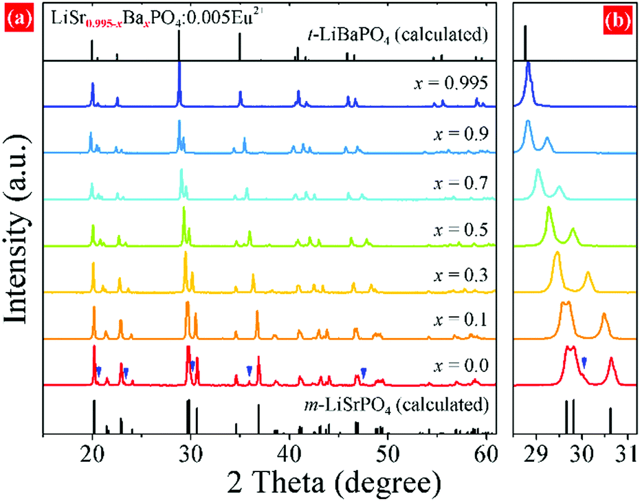
XRD patterns of LiSr0.995–xBaxPO4:0.005Eu2+ (x = 0–0.995) synthesized at 1200 °C are shown in Fig. 1. LiSr0.995PO4:0.005Eu2+ (x = 0) contains the main phase that crystallizes in a new monoclinic (m-) phase as reported before,24 and an impurity phase that can be indexed to m-LiSrPO4 phase (PDF#53-1238) with a lower symmetry than the main phase. It should be noted that pure monoclinic LiSr0.995PO4:0.005Eu2+ can be achieved under sintering in 1000 and 1100 °C. The diffraction peaks exhibit an obvious shift to the small angle side with the increase of Ba content (x). The impurity phase disappears with the introduction of Ba. The magnified diffraction peaks at around 2θ = 30° (Fig. 1b) show not only the shift of peaks but also the tendency of getting closer and finally becoming a single peak for x = 0.995 without Sr atoms. This phenomenon suggests the variation of cell parameters and interplanar spacing and the change of crystal structure at x = 0.995. Kim et al. reported that a slowly-cooled (−5 K h−1) sample crystallized in a monoclinic LiBaPO4, while the quenched sample is trigonal (t-)LiBaPO4.25 Our sample was furnace cooled, which had a much higher speed than 5 K h−1. Therefore, t-LiBa0.995PO4:0.005Eu2+ was reasonable. On the other hand, the t-LiSrPO4 phase is not reported till now. The existence of Sr2+ may have great influence on the phase, therefore, all LiSr0.995−xBaxPO4:0.005Eu2+ (x = 0.1–0.9) samples synthesized at 1200 °C have the same phase as monoclinic LiSr0.995PO4:0.005Eu2+.
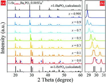 |
| | Fig. 1 (a) XRD patterns of LiSr0.995–xBaxPO4:0.005Eu2+ synthesized at 1200 °C with different Ba2+ concentrations (x), (b) magnified XRD patterns in the 28°–31° range. Peaks assigned by arrows: impurity m-LiSrPO4 phase (PDF#53-1238). | |
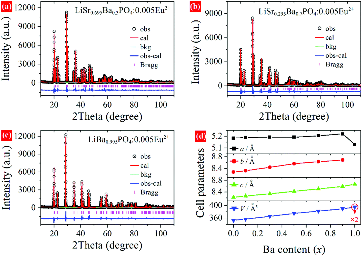
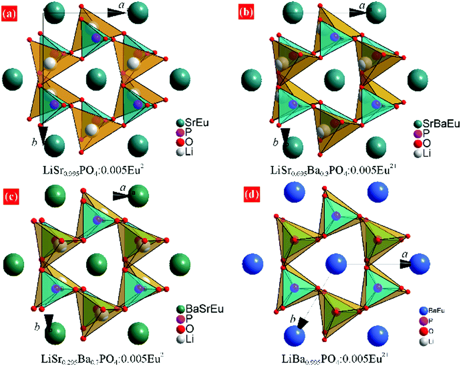
Rietveld refinements were conducted to further study the variation of crystal structure in detail. The crystal data of monoclinic LiBaPO4 reported by Kim et al. were used as a starting model for refinement of samples with x equaling 0–0.9.25 While the refinement for x = 0.995 was based on the crystal structure of trigonal (t-)LiBaPO4.25Fig. 2a–c illustrate refinement results of representative samples, namely x = 0.3, 0.7, and 0.995 that were obtained at 1200 °C. The refinement result for x = 0 can be found in our previous work,24 and the results of others are shown in the ESI† as Fig. S1. The calculated values match well with the observed data. Fig. 2d shows the cell parameters versus Ba content (x). The cell lengths and cell volume tend to increase with Ba content. It should be noted that sample x = 0.995 crystallizes in a different phase compared to others, and has a half number of chemical formulas in a unit cell than others. Therefore, the two times of cell volume for x = 0.995 is larger than the volume of others. Detailed refinement results and crystallographic data are listed in Tables S1–S8 in the ESI.†Fig. 3 illustrates the crystal structures of representative samples viewed along the c axis. Three PO4 and three LiO4 tetrahedrons connect alternately and form a six-member ring. Two parallel rings are also connected by sharing three oxygen atoms, which form a P6Li6 cage. A Sr, Ba, or Eu atom is situated at the center of the cage. Fig. 3 shows that the degree of dislocation between the two parallel six-member rings decreases upon increasing the Ba content. Fig. 4 exhibits the difference in the positions of tetrahedrons. Samples with x = 0 and 0.1 have similar relative positions of PO4 and LiO4, while those with x = 0.3–0.995 have similar relative positions. The difference in the relative positions of PO4 and LiO4 tetrahedrons will result in the variation of coordination polyhedrons for Sr, Ba, and Eu. Table S9 (ESI†) lists Sr/Ba/Eu–O and P–O distances obtained from refinement. The average distance of the nine-coordinated polyhedrons tends to increase with Ba content, which is in accordance with the cell volume. However, it should be noted that there is an abnormally long distance for Sr-rich samples as pointed out in Fig. 4, which is due to the relatively smaller cationic size of the P6Li6 cage.
 |
| | Fig. 2 Rietveld refinement of LiSr0.995–xBaxPO4:0.005Eu2+ synthesized at 1200 °C. (a) x = 0.3, (b) x = 0.7, (c) x = 0.995, (d) cell parameters versus Ba content. | |
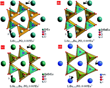 |
| | Fig. 3 Crystal structure of (a) m-LiSr0.995PO4:0.005Eu2+, (b) m-LiSr0.695Ba0.3PO4:0.005Eu2+, (c) m-LiSr0.295Ba0.7PO4:0.005Eu2+, and (d) t-LiBa0.995PO4:0.005Eu2+ from the refinement results. | |
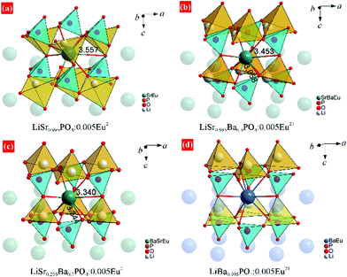 |
| | Fig. 4 Comparison of MO9, PO4, and LiO4 polyhedrons in the crystal structures. (a) m-LiSr0.995PO4:0.005Eu2+, (b) m-LiSr0.695Ba0.3PO4:0.005Eu2+, (c) m-LiSr0.295Ba0.7PO4:0.005Eu2+, and (d) t-LiBa0.995PO4:0.005Eu2+ from the refinement results. | |
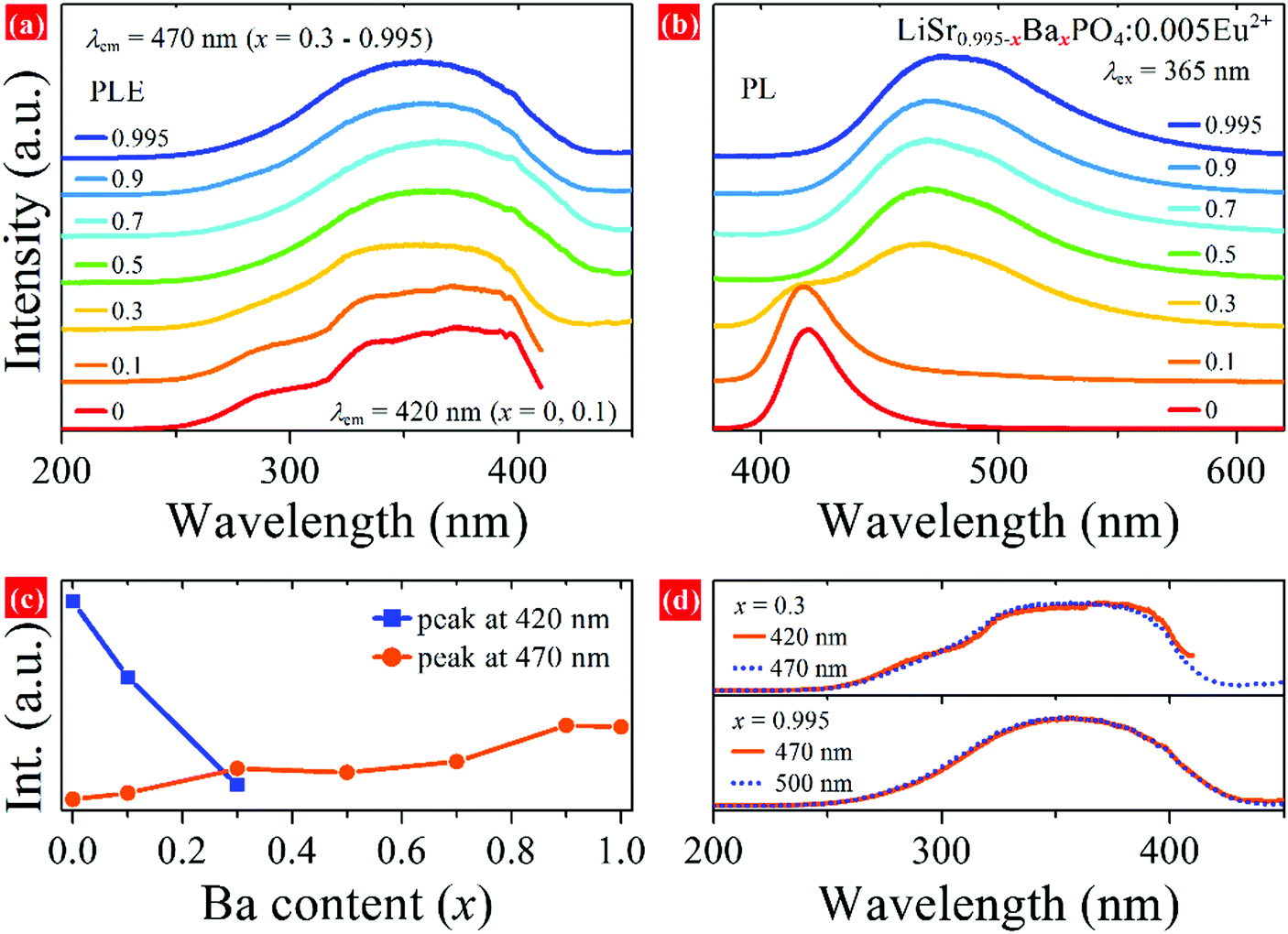
The relative energy of 5d levels of Eu2+ depends on the coordination environment. Therefore, PLE and PL spectra are expected to be tunable by changing the x value in LiSr0.995–xBaxPO4:0.005Eu2+. Fig. 5a and b show PLE and PL spectra of LiSr0.995–xBaxPO4:0.005Eu2+ synthesized at 1200 °C. The PLE spectra of all the phosphors cover the 250–420 nm region with a maximum at around 365 nm, which indicates that all of the phosphors can be excited by near UV light. The profiles of PLE spectra for x = 0 and 0.1 are different from those for x = 0.3–0.995, which relate to the difference in coordination environment for Eu2+. Under excitation at 365 nm, phosphors with x = 0 and 0.1 exhibit a PL band at 420 nm, while those with x = 0.5 – 0.995 have an asymmetric PL band at 470 nm. Phosphor with x = 0.3 possesses both PL bands at 420 and 470 nm. Fig. 5c shows the PL intensity of the two bands versus Ba content (x), which shows a rapid decrease for the 420 nm band from x = 0 to 0.3 and a slight increase of the 470 nm band from x = 0.3 to 0.995. Fig. S2 and S3 (ESI†) show PL spectra and XRD patterns of LiSr0.995–xBaxPO4:0.005Eu2+ synthesized at 1000–1300 °C, respectively. Upon changing the Ba content, similar variations in PL bands and XRD peaks compared to those obtained at 1200 °C were observed. The different PL profile for LiSr0.995PO4:0.005Eu2+ (x = 0) obtained at 1300 °C is due to the formation of the different crystal structure (m-LiSrPO4, PDF#53-1238), which has been discussed in our previous work.24
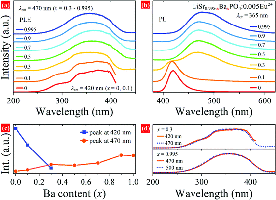 |
| | Fig. 5 PLE and PL spectra of LiSr0.995–xBaxPO4:0.005Eu2+ synthesized at 1200 °C, (a) PLE monitored at 420 or 470 nm, (b) PL excited at 365 nm, (c) PL intensity versus Ba content, (d) normalized PLE spectra monitored at two different wavelengths for x = 0.3 and 0.995. | |
Generally, there are two types of variation for the PL band of Eu2+/Ce3+-activated solid solutions, where the cations occupied by an activator(s) change. The first one is a continuous shift of the PL band if the solid solution leads to the variation of a same crystallographic site occupied by Eu2+ or Ce3+, e.g. Ba2−xSrxSiO4:Ce3+,13Sr1–xBaxSi2O2N2:Eu2+ (x = 0–0.75),32 Ca1−xSrxHf4(PO4)6:Eu2+,33etc. The second one is a discontinuous shift of the PL band if the solid solution leads to the variation of occupancy for Eu2+ or Ce3+ on more than one crystallographic sites, e.g. Li4Sr1+xCa1–x(SiO4)2:Ce3+,18 CsKNa2–yLiy(Li3SiO4)4:Eu2+ (y = 0–1),34etc. It is interesting that no continuous shift of PL band is observed in LiSr0.995–xBaxPO4:0.005Eu2+ series by changing the Ba/Sr ratio, where there is only one Ba/Sr crystallographic site as indicated by the refinement result. It is speculated that environments of SrO9 and BaO9 in LiSr0.995−xBaxPO4:0.005Eu2+ (x = 0.1–0.9) are similar to those in LiSr0.995PO4:0.005Eu2+ (x = 0) and LiBa0.995PO4:0.005Eu2+ (x = 0.995), respectively, based on the variation of PL bands and relative PL intensities, although refinement suggests only one Ba/Sr crystallographic site. SrO9 is dominant in samples with x = 0 and 0.1, which results in a 420 nm PL band after Eu2+ substitution. While Eu2+ tends to occupy the BaO9 site for samples with x = 0.5–0.995, which results in a 470 nm PL band. Eu2+ ions situate on both SrO9 and BaO9 in the sample with x = 0.3; therefore, two PL bands are observed. This phenomenon is similar to that in Eu2+-doped (CaMg)x(NaSc)1−xSi2O6 solid solution, where nano-segregation occurred and allowed predictive control of the relative PL intensity of the two bands with the same profile and wavelength center to the end compounds.19 Therefore, the variation of PL spectra indicates that nano-segregation also happens in the LiSr0.995–xBaxPO4:0.005Eu2+ solid solution.
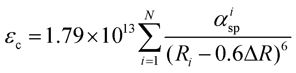
The relationship between emission peak and site coordination environment can be discussed by comparing the crystal field strength (calculation of crystal field splitting), centroid shift of 5d levels for Eu2+, and Stokes shift for Eu2+ on Sr2+ and Ba2+ sites. The average Sr2+/Ba2+/Eu2+–O distances (Rav) are 2.751 and 2.899 Å in LiSr0.995PO4:0.005Eu2+ and LiBa0.995PO4:0.005Eu2+, respectively, according to Table S9 (ESI†). The crystal field splitting (εcfs/eV) can be calculated according to the following equation,35,36
Both Sr
2+ and Ba
2+ are coordinated by nine O atoms, therefore, Eu
2+ on these two sites should have the same
βQpoly value. Eu
2+ on the Sr
2+ site with smaller
Rav has a higher
εcfs value than that on the Ba
2+ site. The centroid shift (
εc/eV) of 5d levels for Eu
2+ can be obtained using the following equation,
35,36| | 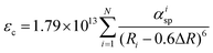 | (2) |
Most Ba–O bonds are longer than those of Sr–O according to Table S9 (ESI
†). The calculated
εc for Eu
2+ on Sr
2+ site is larger than that on Ba
2+ site. The combination of
εc and
εcfs suggests that Eu
2+ on the Sr
2+ site should have a smaller energy difference between the lowest 5d level and 4f ground state than Eu
2+ on the Ba
2+ site, which corresponds to a longer excitation wavelength of the lowest PLE band for Eu
2+ on the Sr
2+ site.
Fig. 5a and d show the excitation spectra monitored at 420 and 470 nm, which is in accordance with the calculation results. The Stokes shift is defined as the energy difference between the peak values of PLE and PL bands. Therefore, it is obvious that the Stokes shift of Eu
2+ on the Ba
2+ site is much higher than that on the Sr
2+ site. Therefore, a huge different Stokes shift of Eu
2+ on Sr
2+ and Ba
2+ sites is the main reason for the difference of emission peaks for Eu
2+ on the two sites.
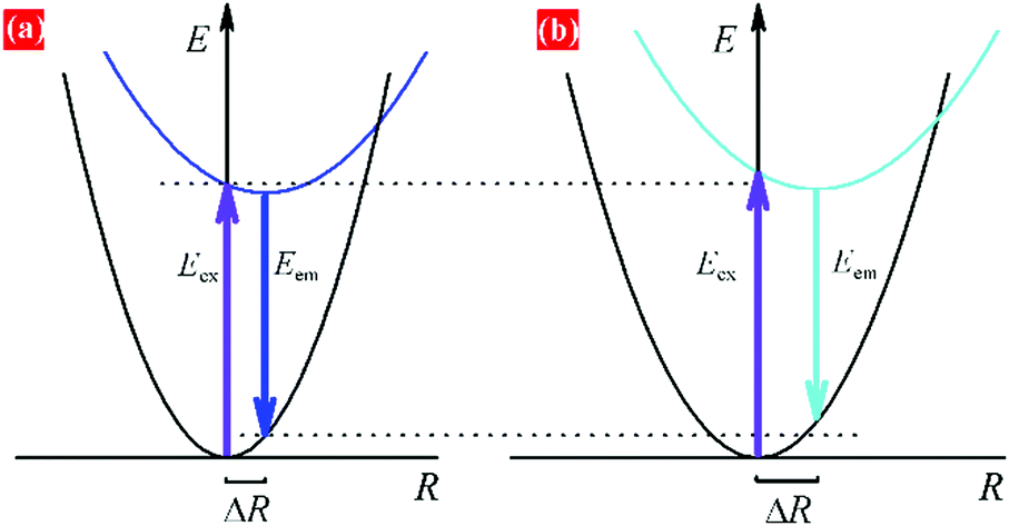
Fig. 6 illustrates the difference for Eu
2+ ions on Sr
2+ and Ba
2+ related sites in the configurational coordinate diagram. For Ba polyhedrons related emission, the excited state of Eu
2+ suffers a larger offset (Δ
R) of the parabola, therefore, resulting in a larger Stokes shift and longer emission wavelength. The PLE bands monitored at 470 and 500 nm for
x = 0.995 also almost overlap, which is consistent, with that, there is only one Ba site in trigonal LiBaPO
4. The m-, t-, and even h-phase differ in the orientation of LiO
4 and PO
4, which results in the variation of Sr/BaO
9 polyhedrons. The change of Ba/Sr ratio is easy to cause the variation of Sr/BaO
9 polyhedrons. Therefore, the unusual asymmetric PL band at 470 nm may originate from Eu
2+ ion on Ba
2+ sites with a slight difference among themselves.
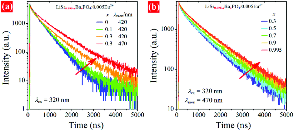
Fig. 7 plots the decay curves of samples monitored at 420 and 470 nm. The different decay behaviors for 420 and 470 nm related emissions for
x = 0.3 again suggest the different coordinate environments. The decay monitored at 420 nm slows down with the increase of Ba
2+ content from
x = 0 to 0.3, which suggests that the change of chemical composition and the decrease of Eu
2+ occupancy on Sr
2+-related site lead to the variation in the nonradiative transition rate.
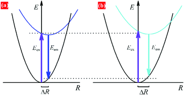 |
| | Fig. 6 Configuration coordinate diagram for Eu2+ ions on (a) Sr and (b) Ba polyhedrons, illustrating the origin of similar PLE bands but different PL bands. | |
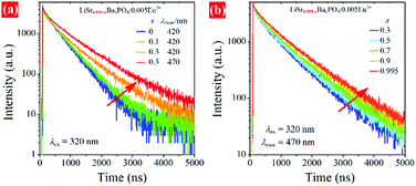 |
| | Fig. 7 Decay curves of LSBPO:0.005Eu2+, (a) monitored at 420 nm for x = 0 – 0.1 and at both 420 and 470 nm for x = 0.3, (b) monitored at 470 nm for x = 0.3 – 0.995. | |
The internal quantum efficiency (QE) of LiSr0.995−xBaxPO4:0.005Eu2+ obtained at 1200 °C was estimated to be about 76.08%, 60.10%, 68.47% and 75.34% for x = 0, 0.3, 0.9, and 0.994, respectively. The QE values of the end compounds are higher than those of solid-solution compounds. Related spectra for QE measurements are shown in Fig. S4 (ESI†). The relationship between QE and decay time can be expressed as13,37
where
τ and
τ0 are the decay times with and without nonradiative transition, respectively. The increase of lifetime for 470 nm emission as indicated in
Fig. 7b is consistent with the increase of QE value from
x = 0.3 to 0.995, which suggests the decrease of nonradiative rate.
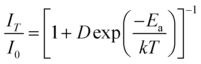
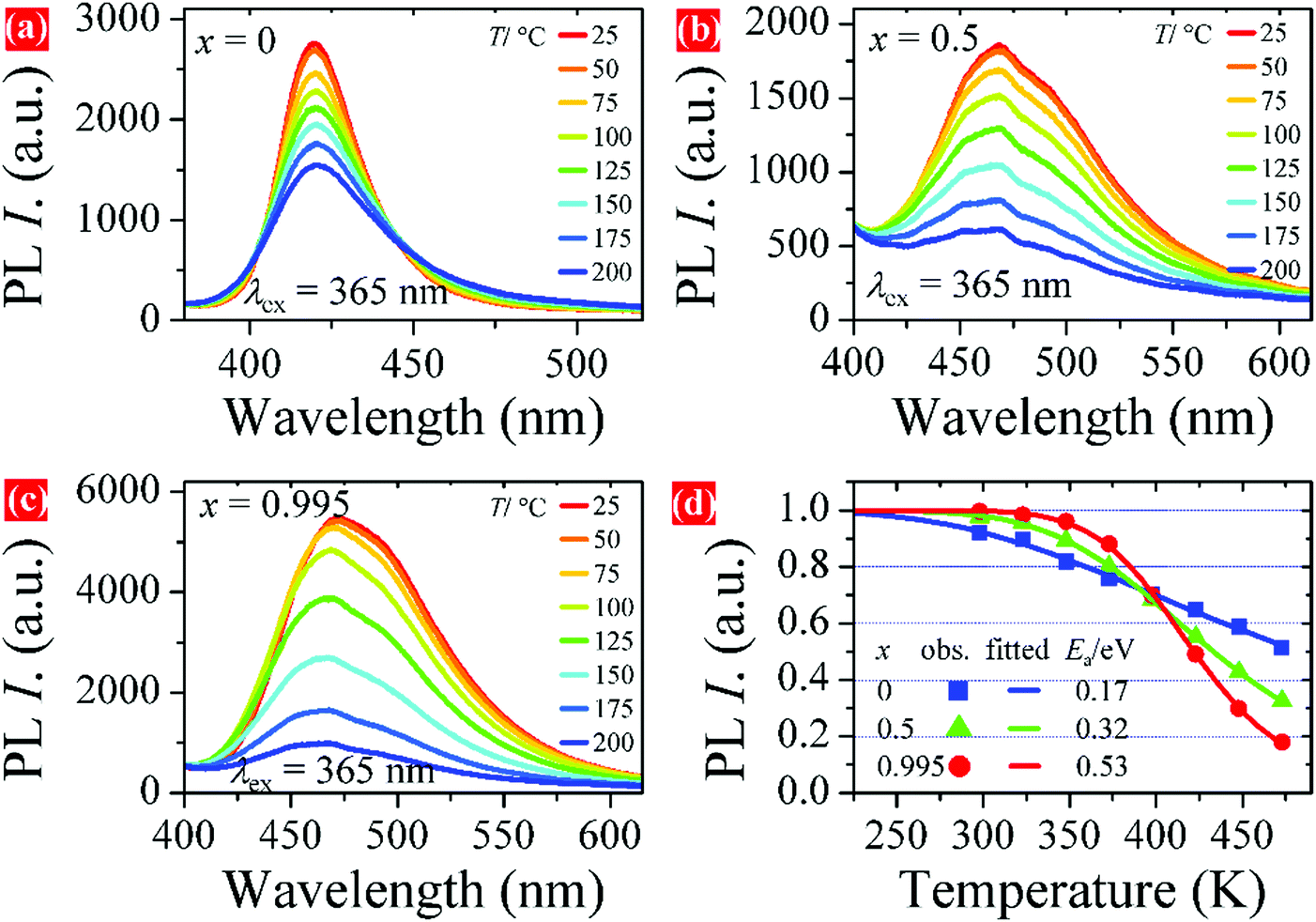
Thermal stability is also an important parameter for phosphors used in pc-LEDs. The temperature-dependent PL spectra of representative samples are shown in Fig. 8a–c. The PL intensity tends to decrease with increasing temperature from room temperature to 200 °C for all samples. Fig. 8d plots the PL intensity versus temperature. It is obvious that the PL intensity of sample x = 0.995 drops slowly from 25 to 100 °C and then faster with a further increase in temperature. While the PL intensity of samples x = 0 and 0.5 decreases smoother than that of x = 0.995 at higher temperatures. The PL intensity of the samples at 125 °C remains at 75% of the initial value at room temperature. The fitted curves in Fig. 8d are achieved by using the Arrhenius formula,38
| | 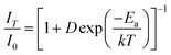 | (4) |
where
IT and
I0 are the PL intensity at temperature
T (in K) and 0 K, respectively.
Ea is the activation energy for thermal quenching.
D is a constant depending on phosphor, and
k is the Boltzmann constant. The fitted
Ea values for
x = 0, 0.5, and 0.995 are 0.17, 0.32, and 0.53 eV, respectively. A higher
Ea value means that it needs more energy for the excited electrons to return to the ground state nonradiatively. The calculated
Ea values are in accordance with the temperature-dependent PL intensity below 125 °C. Furthermore, the PL peak of the samples change little upon increasing temperature. The stability of both PL intensity and peak suggests that LSBPO:0.005Eu
2+ phosphors could be suitable for pc-LEDs.
 |
| | Fig. 8 Temperature-dependent PL spectra of LSBPO:0.005Eu2+, (a) x = 0, (b) x = 0.5, (c) x = 0.995, and (d) PL intensity versus temperature with fitted Ea values. | |
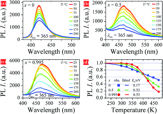
A series of white-emitting pc-LEDs were fabricated by combining LSBPO:0.005Eu2+ phosphors and commercial green-emitting (Ba,Sr)2SiO4:Eu2+, red-emitting CaSiAlN3:Eu2+ with a 365 nm n-UV chip. The electroluminescent (EL) spectra of the pc-LEDs under 50–350 mA forward bias currents are shown in Fig. 9a–c. The performance of the pc-LED based on LiSrPO4:0.005Eu2+ (x = 0) can be found in our previous work, which contains a gap around the cyan-emission region. However, pc-LEDs based on samples x = 0.3, 0.9, and 0.995 can overcome this drawback as these phosphors show emission bands covering the cyan region. All the pc-LEDs have a color-rendering index (Ra) value higher than 90 and a warm white emission with correlated color temperature (CCT) at 3000–4000 K. The EL intensities of pc-LEDs tends to increase with working current, and the EL profile changes little. Luminance efficacies (LE) of the pc-LEDs at 50 mA are shown in Fig. 9. It is believed that the LE values can be improved by optimizing the parameters for pc-LED fabrication, for example, the weight ratio of phosphor to silica gel. Fig. 9d shows the CIE coordinates of the pc-LEDs under different current, detailed CIE values versus current are plotted in Fig. S5 (ESI†). These results suggest that the LSBPO:0.005Eu2+ phosphors can be candidates as blue-emitting component for pc-LEDs based on the n-UV chip.
 |
| | Fig. 9 EL spectra of white pc-LEDs based on LSBPO:0.005Eu2+ phosphors combined with 365 nm chip and commercial green and red phosphors, (a) x = 0.3, (b) x = 0.9, (c) x = 0.995, and (d) CIE coordinates of the pc-LEDs under different currents. | |
Conclusions
In summary, emission-tunable Eu2+-activated LiSr1-xBaxPO4 solid solution was obtained by a high-temperature solid-state reaction. The crystal structure of a recently refined monoclinic phase can be maintained in LiSr0.995−xBaxPO4:0.005Eu2+ for x in 0–0.9 range. While, it crystallizes in a trigonal phase for LiBa0.995PO4:0.005Eu2+ (x = 0.995). The end compounds LiSr0.995PO4:0.005Eu2+ and LiBa0.995PO4:0.005Eu2+ exhibit broad emission bands at 420 and 470 nm, respectively. However, no continuous shift of the emission band is observed in the solid solution, although there is only one crystallographic Sr or Ba site in the crystal structure. The formation of nanosegregation is proposed to explain the variation of emission upon changing Ba/Sr ratio in LiSr0.995−xBaxPO4:0.005Eu2+. The work provides an example of controlled photoluminescence tuning with a discontinuous shift of the emission band. Thermal stability and performance of pc-LEDs suggest that the phosphors can be a candidate as phosphors for solid-state lighting based on n-UV LED.
Conflicts of interest
There are no conflicts of interest to declare.
Acknowledgements
This work is financially supported by Hunan Provincial Natural Science Foundation of China (Grant no. 2019JJ50100), the National Natural Science Foundation of China (Grant no. 21772035, 21505038), and the Scientific Research Fund of Hunan Provincial Education Department (19K024).
Notes and references
- M.-H. Fang, C. O. M. Mariano, P.-Y. Chen, S.-F. Hu and R.-S. Liu, Chem. Mater., 2020, 32, 1748–1759 CrossRef CAS.
- Y. Wang, J. Ding, Y. Wang, X. Zhou, Y. Cao, B. Ma, J. Li, X. Wang, T. Seto and Z. Zhao, J. Mater. Chem. C, 2019, 7, 1792–1820 RSC.
- B. Shao, J. Huo and H. You, Adv. Opt. Mater., 2019, 7, 1900319 CrossRef.
- J. Qiao, J. Zhao, Q. Liu and Z. Xia, J. Rare Earths, 2019, 37, 565–572 CrossRef CAS.
- M. Zhao, Q. Zhang and Z. Xia, Acc. Mater. Res., 2020, 1, 137–145 CrossRef CAS.
- G. Li, Y. Tian, Y. Zhao and J. Lin, Chem. Soc. Rev., 2015, 44, 8688–8713 RSC.
- Y. Wei, L. Cao, L. M. Lv, G. G. Li, J. R. Hao, J. S. Gao, C. C. Su, C. C. Lin, H. S. Jang, P. P. Dang and J. Lin, Chem. Mater., 2018, 30, 2389–2399 CrossRef CAS.
- J. Qiao, L. Ning, M. S. Molokeev, Y.-C. Chuang, Q. Liu and Z. Xia, J. Am. Chem. Soc., 2018, 140, 9730–9736 CrossRef CAS PubMed.
- S. Liao, X. Ji, Y. Liu and J. Zhang, ACS Appl. Mater. Interfaces, 2018, 10, 39064–39073 CrossRef CAS.
- J. Zhong, W. Zhao, F. Du, J. Wen, W. Zhuang, R. Liu, C.-K. Duan, L. Wang and K. Lin, J. Phys. Chem. C, 2018, 122, 7849–7858 CrossRef CAS.
- J. L. Leano, A. Lazarowska, S. Mahlik, M. Grinberg, H. S. Sheu and R. S. Liu, Chem. Mater., 2018, 30, 4493–4497 CrossRef CAS.
- Y.-C. Lin, P. Erhart, M. Bettinelli, N. C. George, S. F. Parker and M. Karlsson, Chem. Mater., 2018, 30, 1865–1877 CrossRef CAS.
- X. Ji, J. Zhang, Y. Li, S. Liao, X. Zhang, Z. Yang, Z. Wang, Z. Qiu, W. Zhou, L. Yu and S. Lian, Chem. Mater., 2018, 30, 5137–5147 CrossRef CAS.
- A. C. Duke, S. Hariyani and J. Brgoch, Chem. Mater., 2018, 30, 2668–2675 CrossRef CAS.
- L. L. Sun, B. Devakumar, J. Liang, S. Y. Wang, Q. Sun and X. Y. Huang, J. Mater. Chem. C, 2020, 8, 1095–1103 RSC.
- M. Zhao, K. Cao, M. Liu, J. Zhang, R. Chen, Q. Zhang and Z. Xia, Angew. Chem., Int. Ed., 2020, 59, 12938–12943 CrossRef CAS PubMed.
- X. X. Sheng, P. P. Dai, Z. Y. Sun and D. W. Wen, Chem. Eng. J., 2020, 395, 125141 CrossRef CAS.
- J. Zhang, J. Zhang, W. Zhou, X. Ji, W. Ma, Z. Qiu, L. Yu, C. Li, Z. Xia, Z. Wang and S. Lian, ACS Appl. Mater. Interfaces, 2017, 9, 30746–30754 CrossRef CAS.
- Z. Xia, G. Liu, J. Wen, Z. Mei, M. Balasubramanian, M. S. Molokeev, L. Peng, L. Gu, D. J. Miller, Q. Liu and K. R. Poeppelmeier, J. Am. Chem. Soc., 2016, 138, 1158–1161 CrossRef CAS.
- G. Li, C. C. Lin, W.-T. Chen, M. S. Molokeev, V. V. Atuchin, C.-Y. Chiang, W. Zhou, C.-W. Wang, W.-H. Li and H.-S. Sheu, Chem. Mater., 2014, 26, 2991–3001 CrossRef CAS.
- Y. Chen, J. Wang, C. Liu, J. Tang, X. Kuang, M. Wu and Q. Su, Opt. Express, 2013, 21, 3161–3169 CrossRef CAS PubMed.
- L. Wang, J. Cui, Q. Shi, Y. Tian, C. Cui, M. Ren and P. Huang, J. Alloys Compd., 2018, 764, 1003–1007 CrossRef CAS.
- C. C. Lin, C.-C. Shen and R.-S. Liu, Chem. – Eur. J., 2013, 19, 15358–15365 CrossRef CAS.
- S. Liao, Y. Li, Y. Zhang, Z. Tan, X. Fu, Z. Qiu and J. Zhang, Appl. Mater. Today, 2020, 21, 100792 CrossRef.
- S.-C. Kim, J. Kim, H. E. Lee, B. J. Kang, F. Rotermund and S.-J. Kim, Solid State Sci., 2018, 83, 76–81 CrossRef CAS.
- Z. C. Wu, J. Liu, M. L. Gong and Q. Su, J. Electrochem. Soc., 2009, 156, H153–H156 CrossRef CAS.
- S. Zhang, Y. Nakai, T. Tsuboi, Y. Huang and H. J. Seo, Chem. Mater., 2011, 23, 1216–1224 CrossRef CAS.
- J. Sun, X. Zhang, Z. Xia and H. Du, J. Appl. Phys., 2012, 111, 013101 CrossRef.
- M. W. Wang, W. Lin, N. Liu and Y. P. Ye, J. Lumin., 2018, 194, 682–685 CrossRef CAS.
- Y. Huang, J. Qin, Z. Fan, D. Wei and H. J. Seo, Inorg. Chem., 2019, 58, 13161–13169 CrossRef CAS PubMed.
- B. H. Toby, EXPGUI, J. Appl. Crystallogr., 2001, 34, 210–213 CrossRef CAS.
- V. Bachmann, C. Ronda, O. Oeckler, W. Schnick and A. Meijerink, Chem. Mater., 2009, 21, 316–325 CrossRef CAS.
- S. Xin, M. Gao, C. Wang, X. Wang, G. Zhu, F. Zhou, Z. Li and Y. Wang, CrystEngComm, 2018, 20, 4383–4394 RSC.
- W. Wang, M. Tao, Y. Liu, Y. Wei, G. Xing, P. Dang, J. Lin and G. Li, Chem. Mater., 2019, 31, 9200–9210 CrossRef CAS.
- P. Dorenbos, J. Lumin., 2002, 99, 283–299 CrossRef CAS.
- P. Dorenbos, J. Lumin., 2003, 105, 117–119 CrossRef CAS.
- Y. Li, Z. Qiu, J. Zhang, X. Ji, X. Zhang, S. Liao, W. Zhou, L. Yu and S. Lian, J. Mater. Chem. C, 2019, 7, 8982–8991 RSC.
- Y.-T. Tsai, C.-Y. Chiang, W. Zhou, J.-F. Lee, H.-S. Sheu and R.-S. Liu, J. Am. Chem. Soc., 2015, 137, 8936–8939 CrossRef CAS PubMed.
Footnote |
| † Electronic supplementary information (ESI) available: Rietveld refinement, cell and atomic parameters, Sr/Ba/Eu–O distances, PL, XRD, spectra for QE, CIE versus current. See DOI: 10.1039/d1ma00950h |
|
| This journal is © The Royal Society of Chemistry 2022 |
Click here to see how this site uses Cookies. View our privacy policy here. 
 Open Access Article
 This Open Access Article is licensed under a Creative Commons Attribution-Non Commercial 3.0 Unported Licence
 *b,
Zhen
Chen
a and
Bing
Yi
*a
*b,
Zhen
Chen
a and
Bing
Yi
*a