 Open Access Article
Creative Commons Attribution 3.0 Unported Licence
Rational design of a zwitterionic porous organic framework loaded with Co(II) ions to host sulfur and synergistically boost polysulfide redox kinetics for lithium sulfur batteries†
Miao
Sun
a,
Gaojie
Yan
a,
Haifeng
Ji
a,
Yi
Feng
a,
Xiaojie
Zhang
 *a and
Jingjing
Shi
*b
aHebei Key Laboratory of Functional Polymers, Department of Polymer Materials and Engineering, Hebei University of Technology, 8 Guangrong Street, Tianjin 300130, P. R. China. E-mail: zhangxj@hebut.edu.cn
bSchool of Science, Nantong University, Nantong, Jiangsu Province 226019, P. R. China. E-mail: shijingjing@ntu.edu.cn
First published on 10th December 2021
Abstract
In the development of lithium–sulfur batteries (LiSBs), the irreversible volume changes, annoying shuttle effect and slow conversion kinetics of lithium polysulfides (LiPSs) are the main obstacles for further commercialization. Therefore, a rational design of a multifunctional sulfur cathode is essential to broaden the application of LiSBs, namely, using a squaraine-linked porous organic framework as the cathode by means of anchoring Co(II) ions into the polar site of the porous structure. The as-obtained Co-HUT4 material maintains an abundant pore structure to house sulfur and gives physical confinement to LiPSs. Besides, the well-dispersed cobalt(II) ions provide good chemical capture sites and catalytic activity, helping to suppress the shuttling effect and enhance the adsorption and conversion of LiPSs. Benefitting from these multifunctional characteristics, LiSBs based on the Co-HUT4 electrode exhibit an exceptional stability of 650 mA h g−1 after 500 cycles at 1.0C, and a specific capacity of 740 mA h g−1 can also be realized with a high sulfur loading (5.5 mg cm−2), which shows remarkable potential for LiSBs.
Introduction
Advanced energy storage systems have always been advocated and upgraded driven by the continuous demand for energy.1,2 As one of the candidates with most potential in next-generation energy storage, lithium–sulfur batteries (LiSBs) hold great superiority because of their high theoretical energy density of 2600 W h kg−1, plentiful natural reserves and the environmental friendliness of the sulfur cathode.3,4 However, there are still certain obstacles with sulfur cathodes that need to be tackled for the commercialization of lithium–sulfur batteries, like the low electrical conductivity of sulfur and Li2S,5 severe volume expansion during charge–discharge cycling6 and the shuttle effect of soluble intermediate lithium polysulfides (LiPSs) during the cycling process.7,8 In order to solve the mentioned problems, it is essential to seek a suitable material as the sulfur host, such as porous carbon,9–11conductive polymers,12 transition metal oxides/nitrides,13–15 and MOF-based materials.16–18 While previous studies have made encouraging progress, it is still a challenge to work out a rational design for multifunctional host materials in an easy way.Recently, a significant number of research studies have indicated that metal oxides, nanoparticles and mixed valence compounds containing transition metals like Mn, Co, Ni, Fe and Cu exhibit outstanding catalytic activity under electrochemical conditions.19–21 For example, Kathiresan and co-workers22 developed a porous organic polymer (POP) embedded with Co nanoparticles as a bifunctional electrocatalyst. However, the reports on the preparation of Co(II) surface-modified porous organic framework materials as the cathode for LiSBs are scanty. As a kind of typical lightweight porous organic polymer, porous organic framework (POF) materials have been extensively studied as cathodes for LiSBs.23–25 The porosity of a POF is conducive to increasing the sulfur content and producing physical confinement on LiPSs. The rigid strut scaffold can suppress the volume expansion during cycling.26 Furthermore, the heteroatoms in POFs can inhibit the shuttle effect by chemical adsorption towards LiPSs.27 Aiming to address these issues of LiSBs and provide a catalytic conversion effect on the reaction kinetics of LiPSs, it is a meaningful strategy to dope transition metals into a POF. Hence, the rational design of POF materials with a large number of reaction centers has become a crucial topic as sulfur carriers to commercialize LiSBs.
Herein, we designed an ideal multifunctional material derived from a novel squaraine-linked porous organic structure, and then embedded it with transition metal ions as its sulfur carrier in the cathode (Scheme 1). Owing to the zwitterionic resonance structure in a squaric acid unit, the constructed functional material can provide a large number of active sites for Co(II) ions to attain a stable complex. To a certain extent, doped with cobalt(II) salt, the positively charged cobalt ions and negatively charged porous frameworks can form a zwitterion-like framework material. On one hand, the porous feature can increase the sulfur content and improve the utilization of active materials. Also, the rigid skeleton can inhibit the volume expansion during charge–discharge cycling. On the other hand, generous Co(II) ions embedded in nanopores can promote chemical adsorption and the catalytic conversion of LiPSs. Combining all the advantages, the prepared Co-HUT4 exhibits a higher Li+ diffusion coefficient, higher current response and smaller Tafel slope, suggesting the rapid conversion kinetics of LiPSs. In addition, the Co-HUT4/S electrode retains a remarkable capacity of 650 mA h g−1 after 500 cycles at 1.0C, counting with a capacity decay of 0.0375% per cycle. A specific capacity of 740 mA h g−1 can also be realized with a high sulfur loading (5.5 mg cm−2), showing remarkable potential in the development of LiSBs. This work highlights the need for rational design of engineering Co(II) ions into polar porous frameworks with effective physical confinement, chemical adsorption and catalytic conversion of LiPSs, and pioneers a shallow strategy to develop suitable matrix materials for high-performance LiSBs.
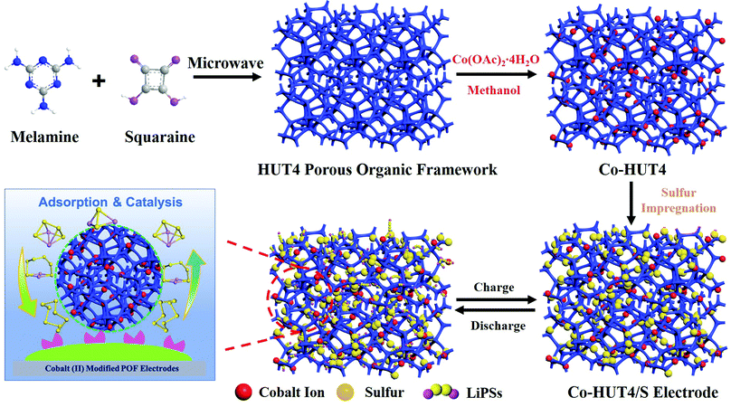 | ||
| Scheme 1 Schematic illustration of the synthetic procedure and mechanism of the Co-HUT4 porous material. | ||
Experimental
Synthesis of HUT4
Squaric acid (272 mg, 2.385 mmol) and melamine (200 mg, 1.586 mmol) were reacted in a mixed solvent of n-butanol and mesitylene (volume ratio 2![[thin space (1/6-em)]](https://www.rsc.org/images/entities/char_2009.gif) :
:![[thin space (1/6-em)]](https://www.rsc.org/images/entities/char_2009.gif) 1) at 120 °C for 2 hours with a microwave synthesizer. In this reaction, the precipitates were washed with acetone, tetrahydrofuran (THF) and dichloromethane (DCM), respectively. The solvent was removed under reduced pressure, and the light-yellow solid powder (HUT4) was produced in a yield of 63%.
1) at 120 °C for 2 hours with a microwave synthesizer. In this reaction, the precipitates were washed with acetone, tetrahydrofuran (THF) and dichloromethane (DCM), respectively. The solvent was removed under reduced pressure, and the light-yellow solid powder (HUT4) was produced in a yield of 63%.
Synthesis of Co-HUT4
50 mg of as-synthesized HUT4 was mixed with a certain amount of Co(OAc)2·4H2O (10 mg, 20 mg, 30 mg, and 40 mg) dissolved in 60 ml of dry methanol. The solution was stirred overnight at room temperature and then washed with a considerable amount of dry methanol. The obtained pink powder named Co-HUT4 was dried under vacuum at 60 °C for 12 hours.Preparation of the Co-HUT4/S electrode
The Co-HUT4/S composite was prepared by the melt-impregnation method. Typically, Co-HUT4 and sulfur powder were well ground in a weight ratio of 1![[thin space (1/6-em)]](https://www.rsc.org/images/entities/char_2009.gif) :
:![[thin space (1/6-em)]](https://www.rsc.org/images/entities/char_2009.gif) 3 in a CS2 solvent, and heated at 155 °C for 12 h to obtain a Co-HUT4/S composite. The following procedure was used to disperse the Co-HUT4/S composite, Super P and polyvinylidene fluoride (PVDF) binders with a mass ratio of 8
3 in a CS2 solvent, and heated at 155 °C for 12 h to obtain a Co-HUT4/S composite. The following procedure was used to disperse the Co-HUT4/S composite, Super P and polyvinylidene fluoride (PVDF) binders with a mass ratio of 8![[thin space (1/6-em)]](https://www.rsc.org/images/entities/char_2009.gif) :
:![[thin space (1/6-em)]](https://www.rsc.org/images/entities/char_2009.gif) 1
1![[thin space (1/6-em)]](https://www.rsc.org/images/entities/char_2009.gif) :
:![[thin space (1/6-em)]](https://www.rsc.org/images/entities/char_2009.gif) 1 homogeneously in 1-methyl-2-pyrrolidinone (NMP). And then the mingled solution was coated on Al foil and dried at 60 °C for 12 h. Later, the slurry-coated Al foil was cut into 10 mm diameter wafers to obtain sulfur electrodes. The sulfur loading of the conventional electrode was 1.7 mg cm−2, but a higher sulfur loading up to 5.5 mg cm−2 could be prepared in the same way. The preparation of the HUT4/S electrode was quite similar to the above-mentioned procedure.
1 homogeneously in 1-methyl-2-pyrrolidinone (NMP). And then the mingled solution was coated on Al foil and dried at 60 °C for 12 h. Later, the slurry-coated Al foil was cut into 10 mm diameter wafers to obtain sulfur electrodes. The sulfur loading of the conventional electrode was 1.7 mg cm−2, but a higher sulfur loading up to 5.5 mg cm−2 could be prepared in the same way. The preparation of the HUT4/S electrode was quite similar to the above-mentioned procedure.
Cell assembling
When assembling CR2032-type coin cells, the sulfur electrode was employed as the cathode, lithium foil as the anode, and the Celgard 2400 membrane as the separator. Moreover, the solution of 1 M LiTFSI with 0.1 M LiNO3 in 1,3-dioxolane (DOL) and 1,2-dimethoxyethane (DME) mixed solvent (1![[thin space (1/6-em)]](https://www.rsc.org/images/entities/char_2009.gif) :
:![[thin space (1/6-em)]](https://www.rsc.org/images/entities/char_2009.gif) 1 in volume) was employed as the electrolyte. The cells were agglomerated in an Ar-filled glove box, in which the moisture and oxygen contents were lower than 0.1 ppm. Before the test, the cells should be kept airtight and stand for 5–6 hours.
1 in volume) was employed as the electrolyte. The cells were agglomerated in an Ar-filled glove box, in which the moisture and oxygen contents were lower than 0.1 ppm. Before the test, the cells should be kept airtight and stand for 5–6 hours.
Density functional theory (DFT) calculations
DFT calculations were used to explain the mechanism of adsorption and catalysis. The structures of HUT4@LiPSs and Co-HUT4@LiPSs were optimized by utilizing ORCA software28 at the B3LYP-D3/def2TZVP level. Then, the binding energies of HUT4@LiPSs and Co-HUT4@LiPSs were obtained by eqn (1) and (2), respectively (“E” represents the electronic energy). The electrostatic potential (ESP) was calculated by using Multiwfn software29 and was drawn using VMD software.30 Moreover, the transition states and intrinsic reaction coordinates of HUT4 and Co-HUT4 adsorbing Li2S2 were searched using Gaussian 1631 at the PBEPBE/6-31G(d) level. In addition, the dendritic structure of HUT4 (C2094H570N1140O954) was built using the Dendrimer module, and the number of atoms reached the limit of the Dendrimer module. Then, powder X-ray diffraction (XRD) patterns of HUT4 were simulated using the Reflex module; since the POF has poor crystallinity and a huge number of atoms, a 10 × 10 × 10 Å box was built to choose a part of HUT4 to simulate the XRD patterns of HUT4 instead of the routine XRD simulation for the crystalline material. All modules in the present description were achieved using Materials Studio 7.0.32| Eb1 = EHUT4@LiPSs − EHUT4 − ELiPSs | (1) |
| Eb2 = ECo-HUT4@LiPSs − ECo − EHUT4 − ELiPSs | (2) |
Results and discussion
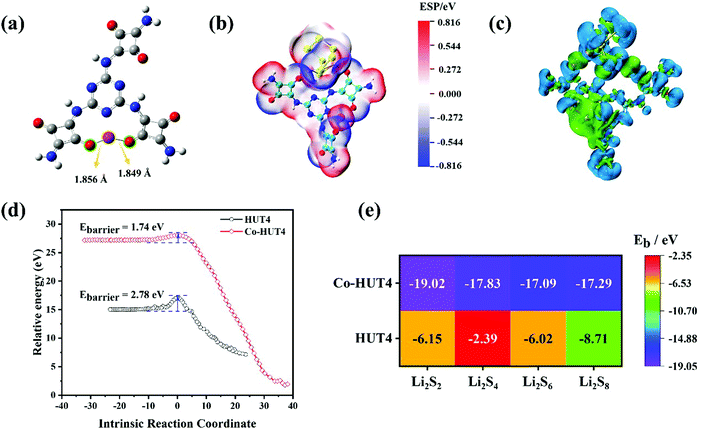
DFT calculations were used to demonstrate that zwitterionic porous organic framework HUT4 loaded with Co(II) ions exhibited excellent performance on adsorbing and fast conversion of LiPSs. The optimized structure of Co-HUT4 (Fig. 1a) indicated that O atoms of squaric acid were able to coordinate with Co(II), and the coordination bond lengths of Co–O were 1.849 Å and 1.856 Å; it was obvious that strong coordination existed between O atoms of HUT4 and Co(II). Then, all optimized structures of HUT4@LiPSs and Co-HUT4@LiPSs (Fig. S1, ESI†) showed that HUT4 and Co-HUT4 were able to adsorb LiPSs. The electrostatic potential (Fig. 1b and others in Fig. S2, ESI†) and charge density differences (Fig. 1c and others in Fig. S3, ESI†) of Co-HUT4@Li2S8 were accurately calculated to prove the excellent ability of Co-HUT4 on absorbing LiPSs. Furthermore, the transition states of HUT4 and Co-HUT4 absorbing Li2S2 (Fig. 1d and Fig. S4, ESI†) were searched to reveal the catalytic activity of Co-HUT4 on the sulfur conversion reaction. Obviously, the energy barrier (Ebarrier) of Co-HUT4 was lower than Ebarrier of HUT4. Therefore, Co-HUT4 was capable of accelerating the LiPS conversion and showed excellent catalytic ability. Since Co-HUT4 exhibited excellent properties on adsorbing and converting LiPSs, Co-HUT4 had a higher binding energy (Fig. 1e) than HUT4, which is in agreement with the analysis of transition states. In brief, a concept was demonstrated that Co-HUT4 exhibited outstanding performance on adsorbing and converting LiPSs using DFT calculations.The synthesis process of Co-HUT4 is shown in Fig. S5 (ESI†). The chemical structure of HUT4 was confirmed by FTIR spectroscopy. As presented in Fig. S6 (ESI†), the absorption peaks at 3416 and 1665 cm−1 are ascribed to the –NH2 stretching vibration and N–H torsional vibration, respectively. The signals at 1506 and 817 cm−1 are attributed to the characteristic absorption peak of the quaternary ring and deformation vibration of the triazine ring, proving that HUT4 had been achieved.33 The 13C NMR spectrum (Fig. S7, ESI†) exhibits a signal at 186 ppm, corresponding to the carbonyl carbon.34 The signals at 148 and 160 ppm correspond to the carbon in the triazine ring, further demonstrating the successful synthesis of HUT4.
The XRD simulation pattern of HUT4 looks like the experimental result (Fig. 2a), similar to the dendritic structure (Fig. 2b and c). However, due to the material's lower crystallinity and imperfect skeleton structure, it does not exactly match with the simulated structure. Significantly, the dendritic structure allowed O atoms coming from squaric acid to easily coordinate with Co(II), which could produce the coordination structure like Fig. 1a. Therefore, the dendritic structure of zwitterionic-POF HUT4 provided a powerful framework to load Co(II).
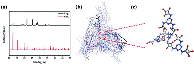 | ||
| Fig. 2 (a) Experimental and simulated XRD pattern of HUT4; (b) dendritic structure and (c) high-magnification dendritic structure unit of HUT4. | ||
The scanning electron microscopy (SEM) images (Fig. 3a) showed the beehive-like structure of HUT4. The transmission electron microscopy (TEM) images shown in Fig. 3b and c confirm the multistage pore structure (30–100 nm) in HUT4, which can be helpful to increase the utilization of sulfur. After the cobalt impregnation, it can be observed that the obtained Co-HUT4 maintains the original nanostructure (Fig. S8, ESI†). Fig. 3d–f showed high-resolution TEM (HRTEM) images and identified area diffraction of Co-HUT4. However, the HRTEM image showed that Co-HUT4 has an amorphous structure, which cannot be consistent with the XRD spectrum (Fig. S9, ESI†). This may be resulted from the high-energy radiation that destroys the original structure of organic materials.35 In addition, compared with the elemental mapping of HUT4 (Fig. 3g), Fig. 3h–i reveal that cobalt is homogeneously distributed in the Co-HUT4.
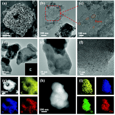 | ||
| Fig. 3 (a) SEM and (b and c) TEM images of HUT4; (d–f) HRTEM images of Co-HUT4; elemental mapping images of HUT4 (g) and (h and i) Co-HUT4. | ||
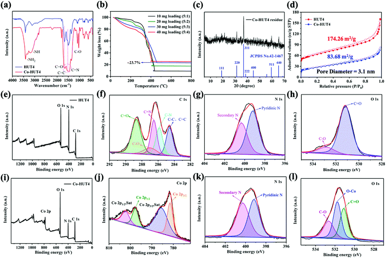
The XRD spectrum of Co-HUT4 (Fig. S9, ESI†) displays the retention of the pristine HUT4 skeleton, which can be also validated by FTIR (Fig. 4a). It can be found that the C![[double bond, length as m-dash]](https://www.rsc.org/images/entities/char_e001.gif) O bond is broadened and the C–O bond is significantly strengthened, which indicates that the Co ion is coordinated with the O atom of HUT4. The Co loading content in the sample was assessed by TGA analysis under an air atmosphere (Fig. 4b), and the saturated content of cobalt in the system was about 17.4%. (After being sintered in air, the Co3O4 phase left was ca. 23.7%, while the molar mass of Co3O4 was 240.7972 g mol−1.) This indicates that the binding sites of cobalt(II) ions are saturated at a mixing ratio of 5
O bond is broadened and the C–O bond is significantly strengthened, which indicates that the Co ion is coordinated with the O atom of HUT4. The Co loading content in the sample was assessed by TGA analysis under an air atmosphere (Fig. 4b), and the saturated content of cobalt in the system was about 17.4%. (After being sintered in air, the Co3O4 phase left was ca. 23.7%, while the molar mass of Co3O4 was 240.7972 g mol−1.) This indicates that the binding sites of cobalt(II) ions are saturated at a mixing ratio of 5![[thin space (1/6-em)]](https://www.rsc.org/images/entities/char_2009.gif) :
:![[thin space (1/6-em)]](https://www.rsc.org/images/entities/char_2009.gif) 3. Consequently, the HUT4 processed with cobalt salt in a mixing ratio of 5
3. Consequently, the HUT4 processed with cobalt salt in a mixing ratio of 5![[thin space (1/6-em)]](https://www.rsc.org/images/entities/char_2009.gif) :
:![[thin space (1/6-em)]](https://www.rsc.org/images/entities/char_2009.gif) 3 was used for further research. Furthermore, the XRD pattern of the residue left (Fig. 4c) was found to be mainly of the Co3O4 phase, and it indicates the successful introduction of cobalt. From the N2 adsorption–desorption isotherm (Fig. 4d), it was estimated that Co-HUT4 preserved a BET specific surface area of 83.68 m2 g−1, which is smaller than that of original HUT4.
3 was used for further research. Furthermore, the XRD pattern of the residue left (Fig. 4c) was found to be mainly of the Co3O4 phase, and it indicates the successful introduction of cobalt. From the N2 adsorption–desorption isotherm (Fig. 4d), it was estimated that Co-HUT4 preserved a BET specific surface area of 83.68 m2 g−1, which is smaller than that of original HUT4.
X-ray photoelectron spectroscopy (XPS) analysis was performed to identify the chemical state of elements in HUT4 and Co-HUT4. It can be observed that the pristine HUT4 possesses only carbon, nitrogen and oxygen elements (Fig. 4e). The binding energy peaks in the C 1s spectrum (Fig. 4f) at 284.6, 285.8, 286.5, 286.9 and 288.6 eV agree with the C–C/C![[double bond, length as m-dash]](https://www.rsc.org/images/entities/char_e001.gif) C, C–N, C
C, C–N, C![[double bond, length as m-dash]](https://www.rsc.org/images/entities/char_e001.gif) N, C–O and C
N, C–O and C![[double bond, length as m-dash]](https://www.rsc.org/images/entities/char_e001.gif) O bonds in HUT4.36 The N 1s XPS spectra (Fig. 4g) show two peaks, which could be ascribed to pyridinic nitrogen (399.2 eV) and secondary nitrogen (400.32 eV), respectively. As shown in Fig. 4h, the O 1s spectrum can be deconvoluted into two oxygen species of O
O bonds in HUT4.36 The N 1s XPS spectra (Fig. 4g) show two peaks, which could be ascribed to pyridinic nitrogen (399.2 eV) and secondary nitrogen (400.32 eV), respectively. As shown in Fig. 4h, the O 1s spectrum can be deconvoluted into two oxygen species of O![[double bond, length as m-dash]](https://www.rsc.org/images/entities/char_e001.gif) C (531.2 eV) and O–C (532.8 eV).37 After cobalt impregnation, a clear Co 2p peak appears in the survey spectrum of Co-HUT4 (Fig. 4i). The Co 2p spectrum of Co-HUT4 displays four peaks (Fig. 4j). The peaks located at 782.0 and 796.2 eV belong to Co 2p3/2 and Co 2p1/2.38 Also, there are two satellite peaks at 786.0 and 804.9 eV related to the high-spin Co2+. However, there is no change in the binding energy of the N 1s spectrum of Co-HUT4 after cobalt impregnation (Fig. 4k). Comparatively, a peak occurs at 531.8 eV corresponding to the Co–O bond (Fig. 4l), suggesting the cobalt ions interact with the oxygen atom during the process of impregnating cobalt.
C (531.2 eV) and O–C (532.8 eV).37 After cobalt impregnation, a clear Co 2p peak appears in the survey spectrum of Co-HUT4 (Fig. 4i). The Co 2p spectrum of Co-HUT4 displays four peaks (Fig. 4j). The peaks located at 782.0 and 796.2 eV belong to Co 2p3/2 and Co 2p1/2.38 Also, there are two satellite peaks at 786.0 and 804.9 eV related to the high-spin Co2+. However, there is no change in the binding energy of the N 1s spectrum of Co-HUT4 after cobalt impregnation (Fig. 4k). Comparatively, a peak occurs at 531.8 eV corresponding to the Co–O bond (Fig. 4l), suggesting the cobalt ions interact with the oxygen atom during the process of impregnating cobalt.
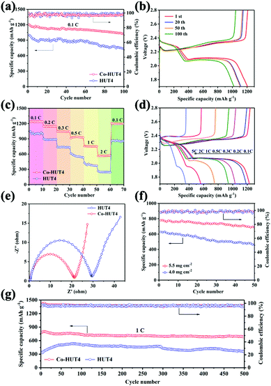
In order to explore the importance of introducing cobalt ions in the electrochemical improvement of LiSBs, CR2032-type coin cells with two types of electrodes were assembled and evaluated. Prior to the cell assembling, TGA analysis (Fig. S10, ESI†) was carried out for HUT4 and Co-HUT4. The decomposition temperature was found to be 300–400 °C approximately, marking that the framework material can exist stably at 155 °C during sulfur impregnation. The sulfur contents (Fig. S11, ESI†) in HUT4/S and Co-HUT4/S composites are around 70% and 73%. Fig. 5a displays the cycling performance in LiSBs with different electrodes at 0.1C. The Co-HUT4/S electrode delivers an initial discharge capacity of 1208 mA h g−1, which is higher than that of the HUT4/S electrode (1023 mA h g−1). In addition, a coulombic efficiency close to 100% is obtained during the 100 cycles, fully demonstrating the excellent cycle stability of rational electrode materials as cathodes. The capacity can be maintained at 1002 and 738 mA h g−1 for Co-HUT4/S and HUT4/S electrodes, respectively, which points out the significantly higher capacity retention and increased sulfur utilization of the Co-HUT4/S electrode. The galvanostatic charge–discharge curves (Fig. 5b) display two discharge plateaus at a higher potential of 2.3 V and a lower potential of 2.0 V, matching with the reduction from sulfur to Li2Sn (2 < n < 8) and further lithiation to Li2S2 and Li2S, respectively. The charge plateaus at 2.3 V show the reverse conversion of Li2S2 (or Li2S) to Li2Sn (2 < n < 8) and finally to sulfur (S8). Remarkably, there is a slight voltage difference between the 1st cycle and 100th cycle, signifying the promoted redox reaction and exceptional electrochemical stability. The rate capability from 0.1C to 2.0C of different electrodes is compared in Fig. 5c. The Co-HUT4/S electrode displays a better rate capability of 1236 mA h g−1 at 0.1C and 570 mA h g−1 at 2.0C. Also, it can deliver a capacity of 1193 mA h g−1 when the rate goes back to 0.1C, showcasing the good reaction reversibility. It can be observed that the discharge capacity decreased as the current rate increased because of the polarization effect (Fig. 5d). The improvement in rate capability can be illustrated with the Co(II) modification enhancing the catalytic activity of the sulfur conversion reaction. Compared with the porous framework without cobalt ions, it promotes the reaction kinetics. Therefore, the Co-HUT4/S electrode presents better rate performance, and it can also be supported by its smaller electrochemical impedance, as shown in the EIS spectrum (Fig. 5e). Further exploration with high sulfur loading based on the Co-HUT4/S electrode was carried out (Fig. 5f), which could be of great significance for LiSBs’ practical application. When the sulfur loading is up to 5.5 mg cm−2, it can reach a stable cycling capacity of 740 mA h g−1. In addition, the long-term cycling ability of two electrodes was measured at a high current density of 1.0C (Fig. 5g) with activation by an initial five cycles at 0.1C to evaluate the electrochemical stability. The initial capacity of the Co-HUT4 electrode is 797 mA h g−1 at 1.0C. After 500 cycles, the capacity can still remain at 650 mA h g−1, accounting for 0.0375% capacity decay per cycle. The specific capacity and cycling stability of electrodes modified with cobalt(II) have been considerably improved, mainly because of the physical confinement and chemical adsorption towards LiPSs.
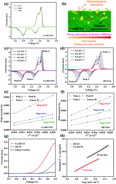
The initial three cycles of CV curves with HUT4/S and Co-HUT4/S electrodes are shown in Fig. 6a and Fig. S12 (ESI†), which were tested at a scan rate of 0.1 mV s−1 in a voltage window of 1.7–2.8 V. Two obvious plateaus emerge at about 2.3 V and 2.0 V during the cathodic scan, corresponding to the reduction of S8 to soluble long-chain LiPSs (Li2Sn, 4 ≤ n ≤ 8) and the further reduction to insoluble Li2S2/Li2S. The oxidation peak at 2.4 V shown in the anodic scan is assigned to the conversion of Li2S2 or Li2S back to S8. The CV results are well matched with the multistep sulfur reaction mechanism, which corresponds to the galvanostatic charge–discharge platform (Fig. 6a). Moreover, the CV curves of Co-HUT4 overlap better than those of HUT4, demonstrating the good cycle reversibility of the electrode during the lithiation/delithiation process. It can be further understood from Fig. 6b that the as-prepared Co-HUT4/S electrode can be considered as a potential electrocatalyst to promote the sulfur conversion owing to the good charge transfer39 as well as the strong interaction with LiPSs. All of these advantages can support a powerful barrier against LiPS diffusion to suppress the LiPS shuttling effectively. The Li+ diffusion properties and reaction kinetics of two kinds of electrodes were investigated on the basis of the CV test (Fig. 6c and d) at different scanning rates varying from 0.1 to 0.4 mV s−1. The Li+ diffusion coefficient (DLi+) is calculated according to the Randles–Sevcik equation: Ip = 2.69 × 10⁵n1.5A(DLi+v)0.5CLi+, which shows that there is a linear correlation between Ip and v0.5. Here, Ip is the peak current, n stands for the electron number transferred in the reaction, A presents the electrode area, DLi+ is the diffusion coefficient of Li+, v indicates the scanning rate, and CLi+ is the concentration of Li+. The linear dependent relationship (Fig. 6e and f) observed for Ip against v0.5 reveals that the redox reaction on the sulfur electrode is dominated by the diffusion process.40 Obviously, the Co-HUT4 electrode delivers a higher DLi+ in all redox states (peaks A, B and C), powerfully confirming that the Li+ diffusion behavior is significantly promoted after cobalt modification. Besides, the linear sweep voltammetry (LSV) measurements were carried out to evaluate the electrocatalytic activity toward Li2S oxidation of Co-HUT4 compared with that of glass carbon and HUT4. As shown in Fig. 6g, the Co-HUT4 electrode exhibits an onset potential of −0.41 V for the Li2S oxidation process, much lower than that of HUT4 (−0.26 V), which signified the lower energy barrier to initiate the Li2S decomposition. The Co-HUT4 electrode displays a higher current response and it corresponds to the rapid oxidation reaction and superior catalytic activity of cobalt ions.41 Furthermore, the Tafel slopes (Fig. 6h) of Co-HUT4 (87 mV dec−1) and HUT4 (77 mV dec−1) are calculated according to the Tafel equation (η = a + b × log![[thin space (1/6-em)]](https://www.rsc.org/images/entities/char_2009.gif) I) to illustrate the relationship between the overpotential (η) and log
I) to illustrate the relationship between the overpotential (η) and log![[thin space (1/6-em)]](https://www.rsc.org/images/entities/char_2009.gif) I. The smaller Tafel slope of Co-HUT4 indicates the faster electron transfer kinetics during the reversible LiPSs conversion process, which can speed up the nucleation and the following conversion of LiPSs to Li2S on the electrode.42
I. The smaller Tafel slope of Co-HUT4 indicates the faster electron transfer kinetics during the reversible LiPSs conversion process, which can speed up the nucleation and the following conversion of LiPSs to Li2S on the electrode.42
With the rewarding features, the kinetics of sulfur redox reactions were estimated by symmetric battery tests. The CV profiles (Fig. S13, ESI†) of symmetric cells with HUT4/S and Co-HUT4/S electrodes were measured within the voltage window of −1.5 to 1.5 V. The Co-HUT4 cell exhibits much higher current response and much smaller polarization than HUT4, representing the fast LiPS conversion kinetics. The CV test of symmetrical cells at different scanning rates was also carried out as shown in Fig. S14 (ESI†). The Co-HUT4 cells deliver a distinctly smaller potential gap than HUT4, further proving the excellent kinetics of LiPS conversion and great catalytic effect of the Co-HUT4.
The introduction of cobalt(II) ions was expected to deliver strong interactions with LiPS species, which can be confirmed by adsorption experiments. The adsorption effect was initially examined by optical observation of immersing the same amount of HUT4 and Co-HUT4 in the Li2S6 solution for 3 hours. In the static adsorption comparison (Fig. 7a), the Co-HUT4/Li2S6 solution displays the lightest color, intuitively indicating the strongest adsorption capacity of LiPSs. UV-Vis spectroscopy further reveals this point with decreased characteristic absorbance peaks after adding Co-HUT4, representing the small residual LiPSs in the supernatant and excellent adsorbability of Co-HUT4. Furthermore, XPS analysis was performed to reveal the chemical interaction between Co-HUT4 and LiPSs. As shown in Fig. 7b, the Li 1s spectrum of pristine Li2S6 manifests a symmetry peak at 55.2 eV, indicating the Li-S bond in LiPSs, while the Li 1s spectrum of LiPS@Co-HUT4 shows a new Li-N/O bond peak at 55.5 eV, foretelling the formation of lithium bonds.43 In addition, the pristine Li2S6 displays two pairs of peaks located at 161.3 and 163.8 eV due to the terminal (ST−1) and bridging (SB0) sulfur, respectively. After adsorbing the Co-HUT4, the peaks moved to a higher binding energy range, and it suggests the decreased electron cloud density of sulfur atoms due to the interaction with Co-HUT4. The other two peaks at 167.9 and 168.0 eV can be respectively linked with the thiosulfate and sulfate.44
 | ||
| Fig. 7 (a) UV-vis spectra and optical observation (inset) of Li2S6 solution adsorbed by HUT4 and Co-HUT4; The (b) Li 1s, (c) S 2p spectra of LiPSs@Co-HUT4. | ||
Conclusions
To conclude, we creatively insert transition metal ions into porous organic frameworks to achieve a novel multifunctional cathode for high-performance LiSBs. The unique porous structure strengthens the physical confinement towards LiPSs, and the rigid skeleton relieves the issue of volume expansion during cycling, to some extent. Moreover, the constructed porous framework can provide lots of polar sites to anchor cobalt(II) ions. The prepared Co-HUT4 sample can act as an electrocatalyst to facilitate the reaction kinetics of LiPSs, and effectively improve the utilization of sulfur. Owing to the mentioned advantages, the Co-HUT4/S electrode can maintain a notable capacity of 650 mA h g−1 after 500 cycles at 1.0C with a low-capacity decay of 0.0375% per cycle, which illustrates its stable performance in long-term cycling. In addition, an excellent capacity of 740 mA h g−1 with high sulfur loading (5.5 mg cm−2) demonstrates its potential in practical applications of LiSBs. Our work confirms the strong physicochemical synergistic adsorption and catalytic conversion mechanism towards LiPSs as a multifunctional electrode. This novel approach inspires a rational design and structural modification of porous framework materials as cathodes for high-performance LiSBs.Author contributions
Miao Sun: performing the experiment and writing the manuscript. Gaojie Yan: DFT calculations. Haifeng Ji: project administration. Yi Feng: guiding the experiment of electrochemical study and related analyses. Xiaojie Zhang: guiding the project and revising the manuscript. Jingjing Shi: guiding the project and funding acquisition.Conflicts of interest
There are no conflicts to declare.Acknowledgements
This work was supported by the National Natural Science Foundation of China (Grant No. 51673192), the Natural Science Foundation of Tianjin City (Grant No. 18JCYBJC43000), and the Natural Science Foundation of Hebei Province (Grant No. B2020202042 and C20200320).References
- S. D. Fu, Q. Yu, Z. H. Liu, P. Hu, Q. Chen, S. H. Feng, L. Q. Mai and L. Zhou, J. Mater. Chem. A, 2019, 7, 11234 RSC.
- R. P. Fang, S. Y. Zhao, Z. H. Sun, D. W. Wang, H. M. Cheng and F. Li, Adv. Mater., 2017, 29, 1606823 CrossRef PubMed.
- M. Zhao, B. Q. Li, H. J. Peng, H. Yuan, J. Y. Wei and J. Q. Huang, Angew. Chem., Int. Ed., 2020, 59, 2 CrossRef.
- H. J. Peng, J. Q. Huang, X. B. Cheng and Q. Zhang, Adv. Energy Mater., 2017, 7, 1700260 CrossRef.
- Z. H. Sun, J. Q. Zhang, L. C. Yin, G. J. Hu, R. P. Fang, H. M. Cheng and F. Li, Nat. Commun., 2017, 8, 14627 CrossRef PubMed.
- M. M. Li, W. J. Feng, W. X. Su and X. Wang, J. Solid State Electrochem., 2019, 23, 2317 CrossRef CAS.
- H. J. Peng, J. Q. Huang, X. Y. Liu, X. B. Cheng, W. T. Xu, C. Z. Zhao, F. Wei and Q. Zhang, J. Am. Chem. Soc., 2017, 139, 8458–8466 CrossRef CAS PubMed.
- J. Xie, B. Q. Li, H. J. Peng, Y. W. Song, M. Zhao, X. Chen, Q. Zhang and J. Q. Huang, Adv. Mater., 2019, 31, 1903813 CrossRef CAS.
- T. T. Li, C. He and W. X. Zhang, J. Energy Chem., 2021, 52, 121 CrossRef.
- X. D. Hong, Y. Liu, J. W. Fu, X. Wang, T. Zhang, S. H. Wang, F. Hou and J. Liang, Carbon, 2020, 170, 119 CrossRef CAS.
- J. R. He, Y. F. Chen and A. Manthiram, Adv. Energy Mater., 2019, 9, 1900584 CrossRef.
- D. D. Han, Z. Y. Wang, G. L. Pan and X. P. Gao, ACS Appl. Mater. Interfaces, 2019, 11, 18427 CrossRef CAS PubMed.
- X. Liang, A. Garsuch and L. F. Nazar, Angew. Chem., Int. Ed., 2015, 54, 3907 CrossRef CAS PubMed.
- C. Wang, Y. K. Yi, H. P. Li, P. W. Wu, M. T. Li, W. Jiang, Z. G. Chen, H. M. Li, W. S. Zhu and S. Dai, Nano Energy, 2020, 67, 104253 CrossRef CAS.
- J. R. He, A. Bhargav, H. Y. Asl, Y. F. Chen and A. Manthiram, Adv. Energy Mater., 2020, 10, 2001017 CrossRef CAS.
- C. Qi, H. L. Li, J. Wang, C. C. Zhao, C. M. Fu, L. Wang and T. X. Liu, ChemElectroChem, 2021, 8, 90 CrossRef CAS.
- J. Yang, B. Wang, F. Jin, Y. Ning, H. Luo, J. Zhang, F. Wang, D. L. Wang and Y. Zhou, Nanoscale, 2020, 12, 4552 RSC.
- H. Zhang, W. Q. Zhao, M. C. Zou, Y. S. Wang, Y. J. Chen, L. Xu, H. S. Wu and A. Y. Cao, Adv. Energy Mater., 2018, 8, 1800013 CrossRef.
- B. Q. Li, S. Y. Zhang, L. Kong, H. J. Peng and Q. Zhang, Adv. Mater., 2018, 30, 1707483 CrossRef PubMed.
- Z. Q. Wang, S. Gu, L. J. Cao, L. Kong, Z. Y. Wang, N. Qin, M. Q. Li, W. Luo, J. J. Chen, S. S. Wu, G. Y. Liu, H. M. Yuan, Y. F. Bai, K. L. Zhang and Z. G. Lu, ACS Appl. Mater. Interfaces, 2021, 13, 514 CrossRef CAS PubMed.
- Y. Jiang, G. H. Ryu, S. H. Joo, X. Chen, S. H. Lee, X. J. Chen, M. Huang, X. Z. Wu, D. Luo, Y. Huang, J. H. Lee, B. Wang, X. Zhang, S. K. Kwak, Z. Lee and R. S. Ruoff, ACS Appl. Mater. Interfaces, 2017, 9, 28107 CrossRef CAS.
- S. Gopi, K. Giribabu, M. Kathiresan and K. Yun, Sustainable Energy Fuels, 2020, 4, 3797 RSC.
- M. Sun, H. F. Ji, Y. N. Guan, Y. Zhang, X. J. Zhang, X. X. Jiang, X. W. Qu and J. D. Li, Nanotechnology, 2021, 32, 85402 CrossRef CAS.
- Z. B. Cheng, H. Pan, H. Zhong, Z. B. Xiao, X. J. Li and R. H. Wang, Adv. Funct. Mater., 2018, 28, 1707597 CrossRef.
- J. Y. Wang, L. P. Si, Q. Wei, X. J. Hong, L. G. Lin, X. Li, J. Y. Chen, P. B. Wen and Y. P. Cai, J. Energy Chem., 2019, 28, 54 CrossRef.
- L. Jiao, C. Zhang, C. N. Geng, S. C. Wu, H. Li, W. Lv, Y. Tao, Z. J. Chen, G. M. Zhou, J. Li, G. W. Ling, Y. Wan and Q. H. Yang, Adv. Energy Mater., 2019, 9, 1900219 CrossRef.
- J. Xu, F. T. Yu, J. L. Hua, W. Q. Tang, C. Yang, S. Z. Hu, S. L. Zhao, X. S. Zhang, Z. Xin and D. F. Niu, Chem. Eng. J., 2020, 392, 123694 CrossRef CAS.
- F. Neese, Wiley Interdiscip. Rev.: Comput. Mol. Sci., 2012, 2, 73 CAS.
- T. Lu and F. W. Chen, J. Comput. Chem., 2012, 33, 580 CrossRef CAS PubMed.
- W. Humphrey, A. Dalke and K. Schulten, J. Mol. Graph., 1996, 14, 33 CrossRef CAS.
- M. J. Frisch, G. W. Trucks, H. B. Schlegel, et al.Gaussian 16, Revision A.03, Gaussian Inc., Wallingford, CT, 2016 Search PubMed.
- Dassault Systèmes BIOVIA, Materials Studio, 7.0, Dassault Systèmes, San Diego, 2017.
- H. B. Aiyappa, J. Thote, D. B. Shinde, R. Banerjee and S. Kurungot, Chem. Mater., 2016, 28, 4375 CrossRef CAS.
- P. Ge, S. J. Li, L. Q. Xu, K. Y. Zou, X. Gao, X. Y. Cao, G. Q. Zou, H. S. Hou and X. B. Ji, Adv. Energy Mater., 2019, 9, 1803035 CrossRef.
- Z. J. Shi, W. J. Feng, X. Wang, M. M. Li, C. K. Song and L. J. Chen, J. Alloys Compd., 2021, 851, 156289 CrossRef CAS.
- X. L. Yang, A. Y. Lu, Y. H. Zhu, M. N. Hedhili, S. X. Min, K. W. Huang, Y. Han and L. J. Li, Nano Energy, 2015, 15, 634 CrossRef CAS.
- L. P. Chen, R. Yang, Y. L. Yan, Y. M. Zou, X. F. Li, Q. J. Deng and Y. H. Xu, Electrochim. Acta, 2020, 362, 137112 CrossRef CAS.
- Y. F. Dong, P. F. Lu, H. D. Shi, J. Q. Qin, J. Chen, W. C. Ren, H. M. Cheng and Z. S. Wu, J. Energy Chem., 2019, 36, 64 CrossRef.
- Y. Tian, G. R. Li, Y. G. Zhang, D. Luo, X. Wang, Y. Zhao, H. Liu, P. G. Ji, X. H. Du, J. D. Li and Z. W. Chen, Adv. Mater., 2020, 32, 1904876 CrossRef CAS.
- J. Y. Wang, G. R. Li, D. Luo, Y. G. Zhang, Y. Zhao, G. F. Zhou, L. L. Shui, X. Wang and Z. W. Chen, Adv. Energy Mater., 2020, 10, 2002076 CrossRef CAS.
- T. Z. Hou, W. T. Xu, X. Chen, H. J. Peng, J. Q. Huang and Q. Zhang, Angew. Chem., Int. Ed., 2017, 56, 8178 CrossRef CAS PubMed.
- X. Liang, A. Garsuch and L. F. Nazar, Angew. Chem., Int. Ed., 2015, 54, 3907–3911 CrossRef CAS PubMed.
- X. B. Wang, Y. Zhao, F. C. Wu, S. M. Liu, Z. S. Zhang, Z. Y. Tan, X. H. Du and J. D. Li, J. Energy Chem., 2021, 57, 19 CrossRef.
- M. F. Chen, Q. Lu, S. X. Jiang, C. Huang, X. Y. Wang, B. Wu, K. X. Xiang and Y. T. Wu, Chem. Eng. J., 2018, 335, 831–842 CrossRef CAS.
Footnote |
| † Electronic supplementary information (ESI) available: DFT calculations, chemicals and instruments, material characterization and electrochemical study. See DOI: 10.1039/d1ma00875g |
| This journal is © The Royal Society of Chemistry 2022 |

