
 Open Access Article
 This Open Access Article is licensed under a Creative Commons Attribution-Non Commercial 3.0 Unported Licence
Atomically dispersed Co–N–C electrocatalysts synthesized by a low-speed ball milling method for proton exchange membrane fuel cells†
Tao
Liu
,
Feng
Sun
,
Meihua
Huang
* and
Lunhui
Guan
 *
*
CAS Key Laboratory of Design and Assembly of Functional Nanostructures, and Fujian Provincial Key Laboratory of Nanomaterials, Fujian Institute of Research on the Structure of Matter, Chinese Academy of Sciences, Fuzhou, Fujian 350002, P. R. China. E-mail: meihuahuang@fjirsm.ac.cn; guanlh@fjirsm.ac.cn
First published on 9th December 2021
Abstract
Atomically dispersed cobalt–nitrogen–carbon (Co–N–C) catalysts have appeared as potential substitutes to costly noble-metal catalysts for the oxygen reduction reaction (ORR) in proton exchange membrane fuel cells (PEMFCs). After carrying out research for a period of time, great progress has been made in preparing atomically dispersed catalysts by pyrolysis of the ZIF-8 precursor. However, the current synthesis method has many disadvantages, such as low reaction conversion, pollution and high cost. To overcome these shortcomings, a low-speed ball milling method was applied to synthesize the precursor of Co–N–C catalysts. The conversion efficiency of the precursor and metal doping rate were greatly improved by ball milling in a micro-solvent environment. Moreover, the environmentally friendly synthesis process does not involve a large amount of organic solvent and metal ions. In addition to the detailed characterization of the single-atom properties of the catalyst by the X-ray absorption fine structure and other means, and a thorough electrochemical characterization demonstrates its ORR capacities (E1/2 = 0.78 V) in acidic media. The test of PEMFCs proved a promising maximum power density (450 mW cm−2) and long-term stability. This work provides a new method and idea for the efficient and green synthesis of high-performance catalysts for commercial application of PEMFCs.
Introduction
The efficient utilization of energy through electrochemical equipment such as proton exchange membrane fuel cells (PEMFCs) and metal–air batteries1,2 brings hope to humanity for reducing greenhouse gas emissions produced by fossil fuel combustion and alleviating the shortage of energy. Nevertheless, the sluggish oxygen reduction reaction (ORR) at the cathode in fuel cells relies heavily on platinum and other precious metal catalysts, which extremely hinder the large-scale commercialization of the fuel cells.3,4 In recent years, dramatic breakthroughs have been made by using atomic non-precious metal catalysts dispersed or/and supported on carbon nano-materials as a result of the high atomic utilization and flexible adjustment between the metal and substrate.5 Metal–organic frameworks (MOFs), such as ZIF-8, are a kind of utility porous material characterized with a massive porous structure, great tunable functionality and constitutive properties, which are expected to be promising as sacrificial templates of metal–nitrogen–carbon for ORR electrocatalysts.6 In recent years, significant progress has been made in the synthesis of atomically dispersed catalysts using ZIF-8 as a template for the ORR, which have become the most promising material to replace commercial Pt-based electrocatalysts.7–9 However, traditional methods for the synthesis of a metal atomically dispersed ZIF-8 template, such as liquid phase synthesis, have a lot of shortcomings. Firstly, a large number of organic solvents are employed in the reaction process, which seriously aggravates the environmental burden and energy consumption.10 Moreover, in the reaction of zinc ions and 2-methylimidazole, the added amount of 2-methylimidazole, as a kind of chemical raw material with high cost, is often far greater than the stoichiometric number, which will cause wastage of a lot of 2-methylimidazole.11 At the same time, due to the low conversion rate, a large amount of waste liquid containing metal ions and organic matter is produced, which will also be a huge challenge for harmless treatment. Undoubtedly, the traditional methods produce a huge obstacle to the large-scale production and promotion of single atomic catalysts, and diverge from to the green direction of hydrogen energy.The synthesis of ZIF-8 structures doped with large amounts of transition metals (e.g., Co) in a solvent-free or micro solvent environment while maintaining a high yield is an ideal approach. Mechanochemical synthesis has been widely studied recently because of its advantages such as stability, high efficiency and high yield12 and has been implemented in miscellaneous fields, such as mineral dressing and synthesis of chemical compounds, and currently it is experiencing a revival because of its successful realization of the synthesis of organic–inorganic nanomaterials.13–15 Nowadays, mechanochemistry has become a cogent and quite widespread method for the preparation of multifarious materials.16,17 The synthesis of ZIF-8 with mechanized methods has been widely developed,18,19 but it mostly involves relatively extreme synthesis parameters such as high rotation speed,20 and high pressure.21 If the reaction is carried out under mild conditions, it will lead to a long reaction time and incomplete reaction and other disadvantages. According to the report described by Tanaka et al.,22 if the low-speed ball milling method (around 200 revolutions per minute (rpm)) was used, a large amount of ZnO was not converted to ZIF-8 even after 240 hours reaction time, let alone additional metal doping. Therefore, it is of practical significance and theoretical value to synthesize transition metal-rich ZIF-8 structures for single-atom catalyst precursors by a relatively mild mechanochemical method.
In this work, we presented a method to synthesize Zn–Co–MOFs by ball milling with micro-solvent and low speed (250 rpm) as the sacrificial templates of Co–N–C electrocatalysts. The typical synthesis procedure is illustrated in Fig. 1. This method has the advantages of a high yield of over 80%, a barely organic solvent involved in the whole reaction process, a convenient reaction and scale-up production. Electrochemical measurements showed that the optimized Co–N–C catalyst (see the ESI† for more details), synthesized by ball milling had a high onset potential and half-wave potential of 0.88 V and 0.78 V in harsh acidic media. It also showed excellent stability with 21 mV decay after 10![[thin space (1/6-em)]](https://www.rsc.org/images/entities/char_2009.gif) 000 accelerated durability tests (ADT). The refreshing catalyst also showed a promising maximum power density (450 mW cm−2) in the PEMFCs. Furthermore, thanks to the rich Co–N structure, the maximum power density of the fuel cell was reduced by only 50 mW cm−2 after 10000 cycles of durability tests.
000 accelerated durability tests (ADT). The refreshing catalyst also showed a promising maximum power density (450 mW cm−2) in the PEMFCs. Furthermore, thanks to the rich Co–N structure, the maximum power density of the fuel cell was reduced by only 50 mW cm−2 after 10000 cycles of durability tests.
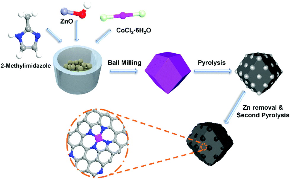 | ||
| Fig. 1 Schematic illustration of the synthesis of Co-120. | ||
Results and discussion
Scanning electron microscopy (SEM) was employed to probe the morphology and configuration of Co-120. As revealed in Fig. 2A, the sample retained an intact crystal structure of ZIF-8, after repeatedly annealing.23 At the same time, it can be seen that the MOF precursor of Co-120, Co-40 and NC has a typical XRD peak of ZIF-8 (Fig. S4, ESI†), so the original crystal structure of the catalyst has been maintained before and after pyrolysis without carbon adhesion and obvious breakage which can be proved in the large-scale pre- and post-pyrolysis SEM of Co-120 (Fig. S3, ESI†).24 In addition, the TEM image did not show any metallic or nonmetallic particles other than carbon (Fig. 2B). Besides, the distributions of C, N, O, Co and Zn in Co-120 are also studied by the EDS mapping analysis. As illustrated in Fig. 2D and F, the uniform distributions of C and N images revealed the homogeneous embedded N atoms into the carbon framework.25 Meanwhile, the high dispersion of Co was also proven by Fig. 2G–I, and Fig. S1 and S2 (ESI†) show that the cobalt site density and nitrogen density in the Co-120 catalyst were significantly increased with the increase of cobalt chloride input.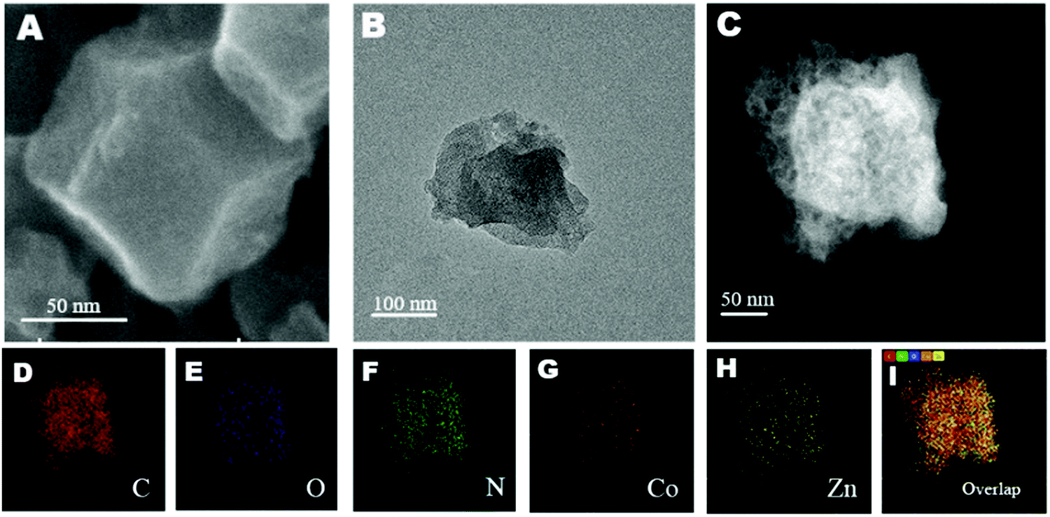 | ||
| Fig. 2 (A) SEM image. (B) TEM image. (C) STEM image. (D–I) HAADF-STEM-EDS elemental mappings of Co-120. | ||
The crystal textures of Co-120, Co-40 and NC were also probed by way of XRD. As revealed in Fig. 3A, the XRD patterns only showed two peaks centered around 23° and 43°, attributed to the [002] and [100] planes of graphite, separately. And no metal crystals were formed in the above samples.26 Also the patterns match the HAADF-STEM image (Fig. D–I), which conjointly demonstrated the uniform distribution of Co on the carbon skeleton.27 However, as shown in Fig. S5 (ESI†), the XRD pattern of Co-200 showed significant peaks of cobalt metal and cobalt oxide, which strongly proved that when the addition of cobalt chloride reached 200 mg, the atomically dispersed properties of Co were lost, so Co-200 was not further characterized.
 | ||
| Fig. 3 (A) XRD patterns of Co-120, Co-40 and NC. (B) Raman spectra, (C) N2 adsorption–desorption isotherms, and (D) the corresponding pore size distribution plots based on DFT analysis of Co-120 and Co-40. | ||
The configuration defects and graphitization level of the synthesized samples were accurately tested by Raman spectroscopy. In this spectrum, both Co-120 and Co-40 reveal two main bands at 1350 and 1580 cm−1(Fig. 3B). And the former was ascribed to the disruption of the graphitic structure and the latter was ascribed to the graphitic G band. As is well known, the intensity ratio (ID/IG) is inversely proportional to the size of the graphitic crystal.28 Transparently, the Co-120 had an almost equal intensity ratio to Co-40, reflecting similar edge sites and graphitic grains. Therefore, the defect degree of Co-120 does not increase with the increase of the proportion of Co.29
The pore structure and surface character of the samples were tested by N2 adsorption–desorption BET methods.30 As shown in Fig. 3C and Table S1 (ESI†), the BET surface area of Co-120 is 956.9 m2 g−1, 36.7% higher than that of Co-40 (700.1 m2 g−1). The pore size distribution analysis displayed that the intensive surface area of Co-120 was due to the improved mesoporous structure (Fig. 3D). This might be attributed to the extra fracturing of the MOF precursor due to the more amount of Co added during the pyrolysis process at high temperature.31
XPS was used to ulteriorly measure the elemental valence states and compositions of the Co-120 sample.32 The survey spectrum identified the proportion of C (82.23%), N (7.46%), O (9.3%), Zn (0.47%), and Co (0.54%) as depicted in Fig. 4D and Table S2 (ESI†). It also displays the successful insertion of Co into a N doped carbon material. The peaks at 782.5 and 780.5 eV in the Co 2p spectrum (Fig. 4C) were associated with the Co2+ and Co3+ sorts of Co 2p3/2, while those at 795.9 and 798.0 eV were associated with the Co2+ and Co3+ sorts of Co 2p1/2.33 Moreover, the two satellite peaks at 786.2 and 802.6 eV revealed the existence of Co–N groups. As mentioned above, the zeroth order signals of Co were not observed in the patterns, which exactly overlapped with the XRD and EDS mapping data. The Co–N groups originated from the strong interactions between the N-doped carbon and Co.34Fig. 4A reveals the C 1s XPS portion, which could be decomposed into three peaks appearing from C![[double bond, length as m-dash]](https://www.rsc.org/images/entities/char_e001.gif) O (287.7 eV), C–N (286.2 eV), and C–C (285.0 eV), meaning the effective insertion of N into the carbon substrate. Moreover, there were four peaks at 404.1, 401.1, 400.0, 398.8 eV in the N 1s XPS portion (Fig. 4B), and were attributed to oxidized N, graphitic N, pyrrolic N and pyridinic N, separately. Among them, pyridinic N with a single electron pair would not only stimulate the ambient carbon atoms, but also enhance the electrochemical strength of the ORR.35 Besides, it should be observed that the binding energies of the nitrogen bound to Co is very low to be probed; therefore, peaks at 399.98 and 398.80 eV could also be attributed to the presence of Co–N.36 Previous research results have shown that a much higher percentage of pyridinic N was generally correlated with the edge rich Co–N4 sites in the samples. In order to study whether the increase of cobalt content in the catalyst affected the number of Co–N structures, the above materials were further explored. It is worth noting that pyridinic N was invariably the main component of Co-120, Co-40 and NC (Fig. 4E and F). And it is obvious that the Co-120 material has a higher pyrrolic N content, which is largely due to the contribution of a large number of Co–N structures.37 By XPS comparison of Co-120 and Co-40 materials (Fig. S6 and Table S2, ESI†), it is found that increasing the amount of Co resulted in the increase in the density of Co sites in the catalyst (from 0.44% to 0.54%), and also caused a jump in the nitrogen content of the material (from 6.32 at% to 7.46 at%). The results also confirmed the existence of the Co–N structure from the side. It can be seen that the Co doping amount of ball milling precursors reached the amount of traditional monatomic synthesis method,38 and has many advantages, such as high yield, green environmental protection and so on. Moreover, it is worth mentioning that Co-120 and Co-40 have a super high nitrogen content of about 7 at%, and a higher N content means more defects, which would provide a broad application space for this material.39
O (287.7 eV), C–N (286.2 eV), and C–C (285.0 eV), meaning the effective insertion of N into the carbon substrate. Moreover, there were four peaks at 404.1, 401.1, 400.0, 398.8 eV in the N 1s XPS portion (Fig. 4B), and were attributed to oxidized N, graphitic N, pyrrolic N and pyridinic N, separately. Among them, pyridinic N with a single electron pair would not only stimulate the ambient carbon atoms, but also enhance the electrochemical strength of the ORR.35 Besides, it should be observed that the binding energies of the nitrogen bound to Co is very low to be probed; therefore, peaks at 399.98 and 398.80 eV could also be attributed to the presence of Co–N.36 Previous research results have shown that a much higher percentage of pyridinic N was generally correlated with the edge rich Co–N4 sites in the samples. In order to study whether the increase of cobalt content in the catalyst affected the number of Co–N structures, the above materials were further explored. It is worth noting that pyridinic N was invariably the main component of Co-120, Co-40 and NC (Fig. 4E and F). And it is obvious that the Co-120 material has a higher pyrrolic N content, which is largely due to the contribution of a large number of Co–N structures.37 By XPS comparison of Co-120 and Co-40 materials (Fig. S6 and Table S2, ESI†), it is found that increasing the amount of Co resulted in the increase in the density of Co sites in the catalyst (from 0.44% to 0.54%), and also caused a jump in the nitrogen content of the material (from 6.32 at% to 7.46 at%). The results also confirmed the existence of the Co–N structure from the side. It can be seen that the Co doping amount of ball milling precursors reached the amount of traditional monatomic synthesis method,38 and has many advantages, such as high yield, green environmental protection and so on. Moreover, it is worth mentioning that Co-120 and Co-40 have a super high nitrogen content of about 7 at%, and a higher N content means more defects, which would provide a broad application space for this material.39
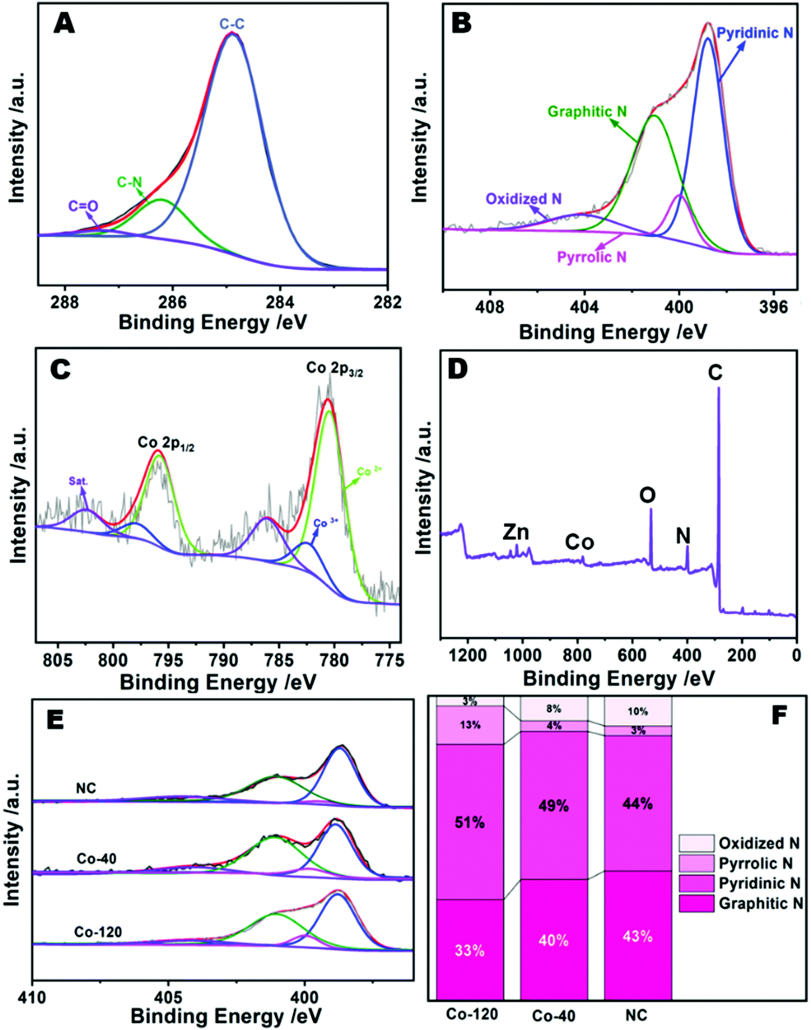 | ||
| Fig. 4 High-resolution C 1s (A), N 1s (B), Co 2p (C), and survey (D) XPS spectra of Co-120. (E) High-resolution N 1s XPS spectra of products obtained at different amounts of Co added. (F) The corresponding N species with different contents. | ||
For further analyzing the active site of catalyst, synchrotron-radiation-based X-ray absorption fine structure (XAFS) methods were employed to identify the refined structure of Co-120 and Co-40 samples.40 As shown in Fig. 5A, the Fourier transform (FT) extended X-ray absorption fine structure (FT-EXAFS) of Co-120 and Co-40 revealed a major peak at approximately 1.4 Å, which were classified as the backscattering between Co and light atoms (N and O). However, EXAFS cannot distinguish between adjacent coordination elements in the periodic table such as Co–N and Co–O. The FT-EXAFS peak at 2.2 Å from the Co foil is connected with Co–Co coordination.6 The weak existence of the Co–Co scattering path in Co-120 proved that most of the Co in Co-120 was in the form of isolated single atoms. At the same time, the result also proved that the ball milling method proposed in this paper could realize the green and efficient preparation of atomically dispersed Co–N catalysts. In order to further prove the single atom dispersion of Co in the synthesized samples, the wavelet transform (WT) analyses were implemented, which could distinguish the backscattering atoms and supply the cogent resolution ratio in both K and R spaces. As revealed in Fig. 5B, the WT skeleton maps of Co-120 and Co-40 introduce one intensity maximal value at around 3.5 Å−1, which could be attributed to the impact from the backscattering between Co and light atoms. Besides, contrasted with the Co foil, the intensity maximum at about 6.7 Å−1 attributed to the Co–Co coordination was not detected in Co-120 and Co-40. The aforesaid evidence well revealed that Co species were atomically dispersed in synthesized samples.38
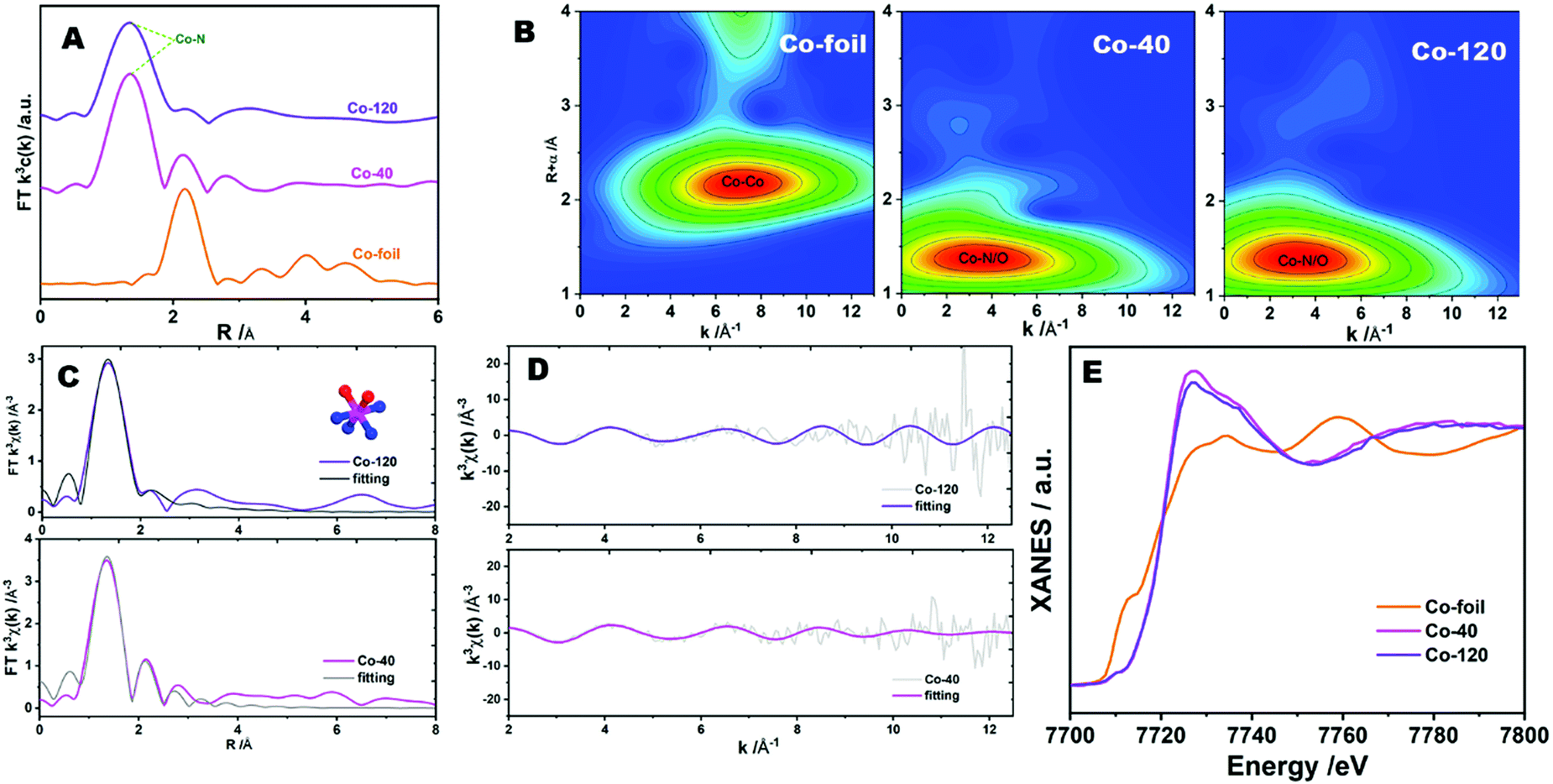 | ||
| Fig. 5 (A) Co K-edge FT-EXAFS spectra and (B) Co K-edge WT-EXAFS contour plots of Co-120, Co-40 and reference samples. (C) Co K-edge EXAFS fitting results for Co-120 and Co-40 in R space and (D) K space. The inset in (C) shows a CoN4O2 moiety used to fit the EXAFS data (the pink, blue, and red spheres represent Co, N, and O, respectively). (E) Co K-edge XANES spectra. | ||
Quantitative least-squares EXAFS curve-fitting operation was performed to check the coordination construction. Two methods of fitting were carried out simultaneously, in which method b introduced O atoms. Method b obtained better fitting results. As revealed in Fig. 5C, D and Table S2 (, ESI†), the first coordination shell of Co-120 and Co-40 might be fitted by a hybrid of Co–N and Co–O coordination paths, with coordinate numbers of 3.9 ± 1.8 (3.6 ± 0.9) and 1.6 ± 0.4 (2.6 ± 0.9), separately. This means that the centric Co sites in the samples possess a CoN4O2 configuration (as shown in the structure diagram in Fig. 5C). The X-ray absorption measurements thus confirmed that the precursors synthesized by the ball milling method contained abundant N, and more Co active sites appeared with the increase of the Co input. At the same time, it could be seen that the increase of Co input was not proportional to the increase of Co content in the catalyst. So, it could be considered that the matching number between Co and N in the precursor has reached or close to saturation when 120 mg cobalt chloride was added. X-ray absorption near-edge structure (XANES) spectroscopy could also present the electronic state of the metal. Fig. 5E reveals the XANES data of Co-120, Co-40 and Co-foil samples, which possessed a quite high distinguishability to the three-dimensional configuration of atoms around the metal center.41 The Co K-edge absorption positions for Co-120 and Co-40 were far away from the Co-foil, showing that the valence state of cobalt in the sample was very different from that of the cobalt element with zero valence.
Cyclic voltammetry was implemented to evaluate the electrochemical ORR performances of Co-120 in 0.1 M HClO4 electrolyte solution. As seen in Fig. 6A, the Co-120 catalyst demonstrated an excellent sharply demarcated cathodic peak in the O2-saturated atmosphere in comparison with the N2-saturated environment, showing the remarkable catalytic competence toward the ORR.42 The linear sweep voltammetry (LSV) curves were collected to further survey the catalytic performance of the Co-120 catalyst for the ORR.33Fig. 6B shows that the Co-120 had more positive Eonset of 0.88 V (vs. RHE) and E1/2 of 0.78 V (vs. RHE) than Co-40 (Eonset = 0.88 V, E1/2 = 0.76 V vs. RHE) and NC (Eonset = 0.77 V, E1/2 = 0.52 V vs. RHE) and the comparable catalytic property compared to the commercial Pt/C (Eonset = 0.98 V, E1/2 = 0.82 V vs. RHE). Co-120 showed obvious strengthening in the catalytic property over Co-40 and NC, which was basically derived from the more active sites of Co–N construction. In addition, by comparing Co-120 and Co-40, the similar onset potential indicated that the two had similar overpotential in the ORR. It could be seen that the improvement of the performance of the Co-120 catalyst was completely due to the improvement of the limited diffusion current density, which indicated that more Co active sites were beneficial to enhance the kinetics of the reaction. Meanwhile, the catalytic features of Co-120 are also superior to many other Co-based ORR catalysts in a harsh acidic medium (Table S4, ESI†).43
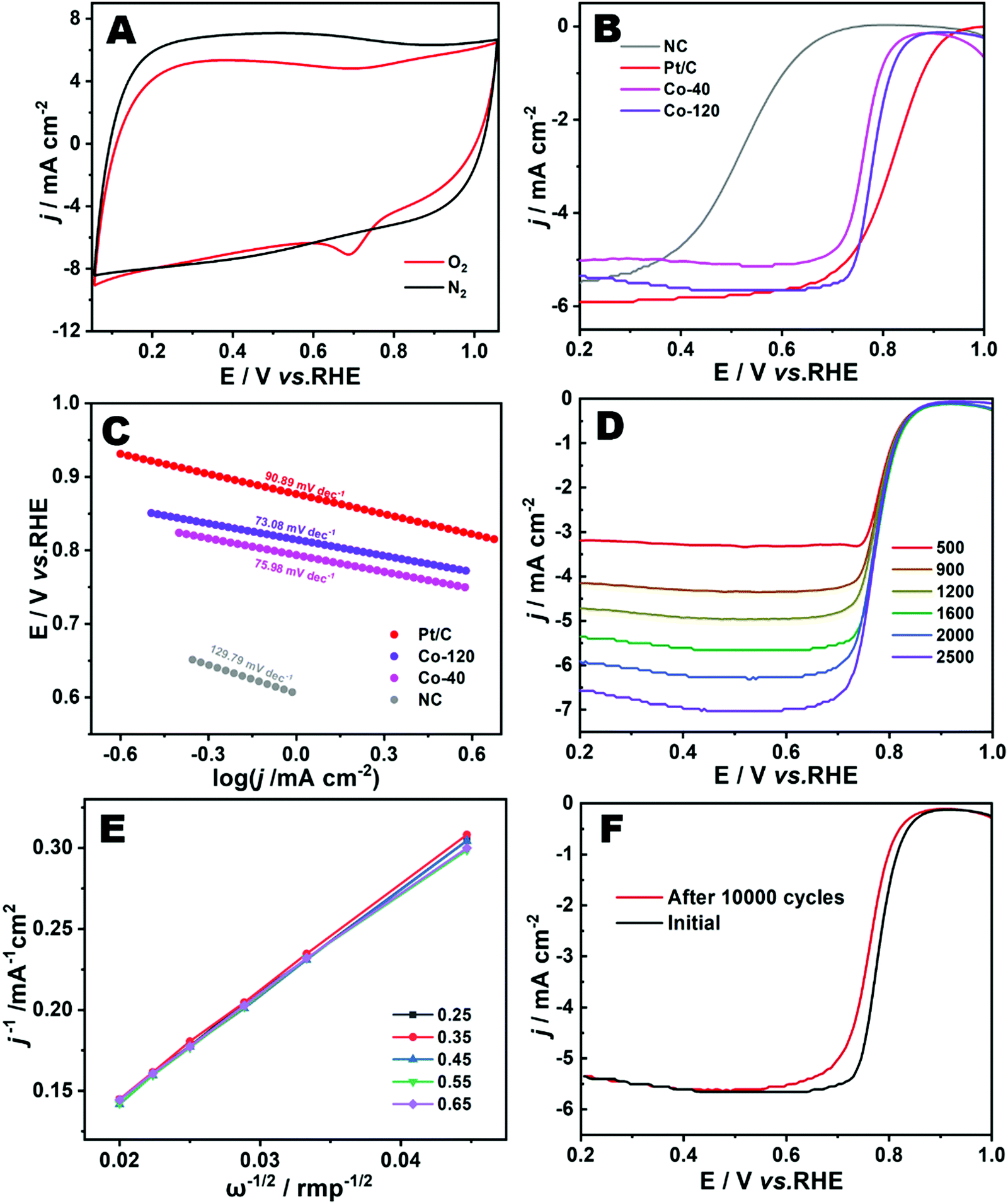 | ||
| Fig. 6 (A) CV curves of Co-120 in N2 and O2 saturated in 0.1 M HClO4 electrolyte at 50 mV s−1. (B) LSV plots of the catalysts recorded in the O2 saturated acid electrolyte at 1600 rpm and a scan rate of 10 mV s−1. (C) Tafel plots of the samples. (D) LSV curves of Co-120 at different rotation rates. (E) K–L plots of Co-120 at different potentials. (F) LSV curves of the Co-120 before and after 10000 cycles at 10 mV s−1. | ||
The wonderful ORR performance of Co-120 could be moreover confirmed via the Tafel slope (Fig. 6C). Clearly, Co-120 showed a lower Tafel slope of 73.08 mV dec−1 in contrast to Co-40 (75.98 mV dec−1), NC (129.79 mV dec−1) and Pt/C (90.89 mV dec−1), which provided evidence of the reinforced activity and electron transfer potency of Co-120 for the ORR.44Fig. 6D shows the LSV curves recorded at different rotating speeds to evaluate the ORR dynamics of Co-120. The K–L plots (Fig. 6E) put forward the linear connection in the potential scope of 0.25–0.65 V (vs. RHE). Explicitly, the electron transfer number of the Co-120 catalyst was close to 3.88, showing that a nearly four-electron ORR pathway occurred at the catalyst.45 Furthermore, the durability of Co-120 was highly significant for a mature catalyst product. After uninterruptedly scanning for 10000 cycles (Fig. 6F), the E1/2 of Co-120 showed a tiny negative shift of 21 mV under extremely harsh acidic conditions.9
Based on the excellent ORR performance and catalytic durability, Co-120 is considered to have great application prospects in proton exchange membrane fuel cells. Peak power density is an important index to evaluate electrocatalysts in PEMFCs.7 Therefore, membrane electrode assemblies (MEA) of Co-120 and Co-40 catalysts were prepared, and the fuel cell polarization curve was tested to characterize the maximum power density of the PEMFCs. Different from the traditional non-precious metal based fuel cell test equipment, a commercial test fixture (Fig. 7A), so as to restore the real working conditions of the vehicle fuel cell as far as possible.46 The schematic diagram of the fuel cell is shown in Fig. 7B. When the oxygen or hydrogen enters the fuel cell from the cathode and anode, respectively, the reaction occurs in their respective catalyst layers and the final reaction product is water. Fig. 7C shows the polarization curves of Co-120 and Co-40 catalysts. It could be seen that compared with the Co-40 catalyst, the Co-120 catalyst has a maximum power density close to 450 mW cm−2, and the leading level is reached among similar catalysts (Table S5, ESI†). At the same time, the polarization curve does not show severe voltage loss due to insufficient mass transfer in the high current region, which is related to the high mesoporous proportion of Co-120. And the role of mesopores in the fuel cell catalyst layer has been widely proved.47 Different from the durability test of the rotating disc electrode, the durability of fuel cells has more practical significance.48 The durability of the cathode catalyst was surveyed by ADTs in the scanning electric potential range from 0.6–1.0 V at 80 °C. Fig. 7D shows impressive durability results of the fuel cell, showing that the maximum power density decreased by only 60 mW after 10000 ADT cycles. Fuel cell assembly and testing of commercial platinum carbon (Pt/C 20%) were carried out under the same test conditions, and a maximum power density close to 580 mW cm−2 was obtained (Fig. S7, ESI†). Similarly, heavy losses (about 120 mW cm−2) occurred after 10000 durability cycles. Compared with commercial platinum carbon, the Co-120 catalyst has excellent durability in fuel cells, mainly because it is difficult to dissolve or collapse the highly dispersed or nearly single-atom dispersed Co–N structure under the harsh acidic conditions of fuel cells compared with metal nanoparticles or atomic clusters.49 Although the Co-120 catalyst showed a relatively reasonable power density in fuel cells, it still had a certain gap with platinum-based catalysts such as commercial platinum carbon. This is mainly due to the fact that the non-noble metal catalyst still has a large gap in mass activity compared with the platinum-based catalyst, and the PEMFC performance of non-noble metal catalysts can only be improved by increasing the load, namely the load of the membrane electrode, to obtain a greater power density. However, the higher load means that the thickness of the catalyst layer in the membrane electrode suddenly increases (four to six times the thickness of a similar platinum-based catalyst). Therefore, a thicker catalyst layer means that the proton transport path is more rugged, which is mainly reflected in the fact that the water generated in the cathode catalyst layer cannot be removed in time and finally causes flooding.50 A thicker catalyst layer means a more rugged proton transport path, which not only increases the internal resistance but also affects the output performance of the fuel cell, such as cathode flooding and oxygen transport obstruction.51
 | ||
| Fig. 7 (A) The diagram of a single cell in PEMFCs. (B) Schematic diagram of a proton exchange membrane fuel cell. (C) Polarization and power density plots of PEMFCs in 1.5 bar H2–O2 of Co-120 and Co-40. (D) Fuel cell polarization plots with Co-120 before and after 10000 ADT cycles. | ||
Conclusions
In this paper, a strategy for obtaining an atomically dispersed Co catalyst from a Zn–Co–MOF synthesized by low-speed ball milling was proposed, which has the advantages of high yield, environmental friendliness, high metal doping and high nitrogen content. It was further proved that the catalyst had excellent ORR performance and stability, and the doping amount of Co is optimized. In addition, the synthesized materials had been assembled and tested for proton exchange membrane fuel cells, and the results showed that the Co-120 exhibited superior H2–O2 PEMFC performance and durability. The method for preparing an atomically dispersed cobalt catalyst by ball milling proposed in this paper provides a new way for mass production and commercialization of atomically dispersed catalysts.Conflicts of interest
The authors declare that they have no known competing financial interests or personal relationships that could have appeared to influence the work reported in this paper.Acknowledgements
We thank the staff of the 11B beamline at the Shanghai Synchrotron Radiation Facility (SSRF) for data collection. This research was supported by the National Natural Science Foundation of China (Grant no. 21771184 and U1932119) and “National Key Basic Research Program of China” (2017YFA0403402). This work was also supported by CAS-Shanghai Science Research Center and user Experiment Assist System of SSRF.References
- C. X. Zhao, J. N. Liu, J. Wang, D. Ren, J. Yu, X. Chen, B. Q. Li and Q. Zhang, Adv. Mater., 2021, 33, 2008606 CrossRef CAS PubMed.
- H. Qin, Y. Wang, B. Wang, X. Duan, H. Lei, X. Zhang, H. Zheng, W. Zhang and R. Cao, J. Energy Chem., 2021, 53, 77–81 CrossRef.
- J. Wang, Z. Huang, W. Liu, C. Chang, H. Tang, Z. Li, W. Chen, C. Jia, T. Yao, S. Wei, Y. Wu and Y. Li, J. Am. Chem. Soc., 2017, 139, 17281–17284 CrossRef CAS PubMed.
- L. Wang, X. Wan, S. Y. Liu, L. Xu and J. L. Shui, J. Energy Chem., 2019, 39, 77–87 CrossRef.
- S. Ji, Y. Chen, X. Wang, Z. Zhang, D. Wang and Y. Li, Chem. Rev., 2020, 120, 11900–11955 CrossRef CAS PubMed.
- Y. Chen, R. Gao, S. Ji, H. Li, K. Tang, P. Jiang, H. Hu, Z. Zhang, H. Hao, Q. Qu, X. Liang, W. Chen, J. Dong, D. Wang and Y. Li, Angew. Chem., Int. Ed., 2021, 60, 3212–3221 CrossRef CAS PubMed.
- Y. Li, P. Zhang, L. Wan, Y. Zheng, X. Qu, H. Zhang, Y. Wang, K. Zaghib, J. Yuan and S. Sun, Adv. Funct. Mater., 2021, 31, 2009645 CrossRef CAS.
- H. Zhang, H. T. Chung, D. A. Cullen, S. Wagner, U. I. Kramm, K. L. More, P. Zelenay and G. Wu, Energy Environ. Sci., 2019, 12, 2548–2558 RSC.
- Q. Wang, Y. Yang, F. Sun, G. Chen, J. Wang, L. Peng, W. T. Chen, L. Shang, J. Zhao and D. Sun-Waterhouse, Adv. Energy Mater., 2021, 2100219 CrossRef CAS.
- K. Singh, E. B. Tetteh, H. Y. Lee, T. H. Kang and J. S. Yu, ACS Catal., 2019, 9, 8622–8645 CrossRef CAS.
- H. Qiangqiang, G. Heze and D. Hongjing, Prog. Chem., 2020, 32, 656 Search PubMed.
- B. Szczęśniak, S. Borysiuk, J. Choma and M. Jaroniec, Mater. Horiz., 2020, 7, 1457–1473 RSC.
- N. R. Rightmire and T. P. Hanusa, Dalton Trans., 2016, 45, 2352–2362 RSC.
- M. J. Munoz-Batista, D. Rodriguez-Padron, A. R. Puente-Santiago and R. Luque, ACS Sustainable Chem. Eng., 2018, 6, 9530–9544 CrossRef CAS.
- D. Tan and F. García, Chem. Soc. Rev., 2019, 48, 2274–2292 RSC.
- V. K. Singh, A. Chamberlain-Clay, H. C. Ong, F. León, G. Hum, M. Y. Par, P. Daley-Dee and F. García, ACS Sustainable Chem. Eng., 2021, 9, 1152–1160 CrossRef CAS.
- K. J. Ardila-Fierro and J. G. Hernández, ChemSusChem, 2021, 14, 2145–2162 CrossRef CAS PubMed.
- A. Parulkar and N. A. Brunelli, Ind. Eng. Chem. Res., 2017, 56, 10384–10392 CrossRef CAS.
- T. Friščić, I. Halasz, P. J. Beldon, A. M. Belenguer, F. Adams, S. A. Kimber, V. Honkimäki and R. E. Dinnebier, Nat. Chem., 2013, 5, 66–73 CrossRef PubMed.
- P. J. Beldon, L. Fábián, R. S. Stein, A. Thirumurugan, A. K. Cheetham and T. Friščić, Angew. Chem., 2010, 122, 9834–9837 CrossRef.
- L. Paseta, G. Potier, S. Sorribas and J. Coronas, ACS Sustainable Chem. Eng., 2016, 4, 3780–3785 CrossRef CAS.
- S. Tanaka, T. Nagaoka, A. Yasuyoshi, Y. Hasegawa and J. F. Denayer, Cryst. Growth Des., 2018, 18, 274–279 CrossRef CAS.
- Y. Lü, W. Zhan, Y. He, Y. Wang, X. Kong, Q. Kuang, Z. Xie and L. Zheng, ACS Appl. Mater. Interfaces, 2014, 6, 4186–4195 CrossRef PubMed.
- A. Song, W. Yang, W. Yang, G. Sun, X. Yin, L. Gao, Y. Wang, X. Qin and G. Shao, ACS Sustainable Chem. Eng., 2017, 5, 3973–3981 CrossRef CAS.
- L. Chen, Y. Zhang, X. Liu, L. Long, S. Wang, X. Xu, M. Liu, W. Yang and J. Jia, Carbon, 2019, 151, 10–17 CrossRef CAS.
- A. E. Awadallah, A. A. Aboul-Enein, U. F. Kandil and M. R. Taha, Mater. Chem. Phys., 2017, 191, 75–85 CrossRef CAS.
- Z. Zhao, Z. Zhu, X. Bao, F. Wang, S. Li, S. Liu and Y. Yang, ACS Appl. Mater. Interfaces, 2021, 13, 9820–9829 CrossRef CAS PubMed.
- J. F. Deng, C. Liu and M. Madou, Nanoscale, 2021, 13, 16094–16103 RSC.
- F. Wang, L. Chen, H. Li, G. Duan, S. He, L. Zhang, G. Zhang, Z. Zhou and S. Jiang, Chin. Chem. Lett., 2020, 31, 1986–1990 CrossRef CAS.
- Y. Wang, Y. Wang, L. Zhang, C.-S. Liu and H. Pang, Inorg. Chem. Front., 2019, 6, 2514–2520 RSC.
- G. Huang, D. Yin and L. Wang, J. Mater. Chem. A, 2016, 4, 15106–15116 RSC.
- X. Xu, Z. Xia, X. Zhang, R. Sun, X. Sun, H. Li, C. Wu, J. Wang, S. Wang and G. Sun, Appl. Catal., B, 2019, 259, 118042 CrossRef CAS.
- Z. Wang, J. Ang, B. Zhang, Y. Zhang, X. Y. D. Ma, T. Yan, J. Liu, B. Che, Y. Huang and X. Lu, Appl. Catal., B, 2019, 254, 26–36 CrossRef CAS.
- S. Song, T. Qin, Q. Li, Y. Wang, Y. Tang, L. Zhang and X. Liu, Inorg. Chem., 2021, 60, 7498–7509 CrossRef CAS PubMed.
- Y. Wan, J. Xu and R. Lv, Mater. Today, 2019, 27, 69–90 CrossRef CAS.
- W. Zhang, X. Yao, S. Zhou, X. Li, L. Li, Z. Yu and L. Gu, Small, 2018, 14, 1800423 CrossRef PubMed.
- X. R. Wang, J. Y. Liu, Z. W. Liu, W. C. Wang, J. Luo, X. P. Han, X. W. Du, S. Z. Qiao and J. Yang, Adv. Mater., 2018, 30, 1800005 CrossRef PubMed.
- Y. He, Q. Shi, W. Shan, X. Li, A. J. Kropf, E. C. Wegener, J. Wright, S. Karakalos, D. Su, D. A. Cullen, G. Wang, D. J. Myers and G. Wu, Angew. Chem., Int. Ed., 2021, 60, 9516–9526 CrossRef CAS PubMed.
- L. Zhang, Z. Su, F. Jiang, L. Yang, J. Qian, Y. Zhou, W. Li and M. Hong, Nanoscale, 2014, 6, 6590–6602 RSC.
- S. Bordiga, E. Groppo, G. Agostini, J. A. van Bokhoven and C. Lamberti, Chem. Rev., 2013, 113, 1736–1850 CrossRef CAS PubMed.
- A. Bergmann, T. E. Jones, E. M. Moreno, D. Teschner, P. Chernev, M. Gliech, T. Reier, H. Dau and P. Strasser, Nat. Catal., 2018, 1, 711–719 CrossRef CAS.
- X. Duan, S. Ren, N. Pan, M. Zhang and H. Zheng, J. Mater. Chem. A, 2020, 8, 9355–9363 RSC.
- J. Choi, Y. J. Lee, D. Park, H. Jeong, S. Shin, H. Yun, J. Lim, J. Han, E. J. Kim, S. S. Jeon, Y. Jung, H. Lee and B. J. Kim, Energy Environ. Sci., 2020, 13, 4921–4929 RSC.
- L.-F. Zhai, S.-Y. Kong, H. Zhang, W. Tian, M. Sun, H. Sun and S. Wang, Chem. Eng. Sci., 2019, 194, 45–53 CrossRef CAS.
- W. Gu, L. Hu, J. Li and E. Wang, Electroanalysis, 2018, 30, 1217–1228 CrossRef CAS.
- K. Ye, G. Wang, D. Cao and G. Wang, Top. Curr. Chem., 2018, 376, 1–38 CrossRef CAS PubMed.
- R. Othman, A. L. Dicks and Z. Zhu, Int. J. Hydrogen Energy, 2012, 37, 357–372 CrossRef CAS.
- Z. Yang, H. Nie, X. Chen and S. Huang, J. Power Sources, 2013, 236, 238–249 CrossRef CAS.
- X. Huang, T. Shen, T. Zhang, H. Qiu, X. Gu, Z. Ali and Y. Hou, Adv. Energy Mater., 2020, 10, 1900375 CrossRef CAS.
- A. Z. Weber and J. Newman, Chem. Rev., 2004, 104, 4679–4726 CrossRef CAS PubMed.
- S. Choi, S. Yuk, D.-H. Lee, G. Doo, D. W. Lee, M.-J. Choo and H.-T. Kim, Electrochim. Acta, 2018, 268, 469–475 CrossRef CAS.
Footnote |
| † Electronic supplementary information (ESI) available. See DOI: 10.1039/d1ma00809a |
| This journal is © The Royal Society of Chemistry 2022 |