 Open Access Article
Electronic structure of Li+@C60 adsorbed on methyl-ammonium lead iodide perovskite CH3NH3PbI3 surfaces†
Khian-Hooi
Chew
 *a,
Riichi
Kuwahara
 b and
Kaoru
Ohno
 c
c
aDepartment of Physics, University of Malaya, 50603 Kuala Lumpur, Malaysia. E-mail: khchew@um.edu.my
bDassault Systèmes, ThinkPark Tower, 2-1-1 Osaki, Shinagawa-ku, Tokyo 141-6020, Japan
cDepartment of Physics, Yokohama National University, 79-5 Tokiwadai, Hogogaya-ku, Yokohama 240-8501, Japan
First published on 13th October 2021
Abstract
It was recently shown by Jeon et al. [Angew. Chem., 2018, 57, 4607] that air stability for more than 1000 hours under light illumination can be achieved in methyl-ammonium (MA) lead iodide perovskite solar cells when Li+ is replaced by Li+@C60 in a dopant material used in the p-type donor layer. In order to demonstrate the role of Li+@C60 in the hole transporting material, we carried out first-principles electronic structure calculations of Li+@C60 adsorbed on MAPbI3 using the van der Waals corrected density functional theory. We used finite slab models of tetragonal MAPbI3 (001) surfaces with MAI terminations. Using the most stable MAPbI3 surfaces, we introduced one Li+@C60 molecule on various positions of the MAI surface and performed geometrical optimizations. Then, we found that the Li+@C60 was adsorbed at the aboveC position with almost 100% ionization. There is not much difference between the top and bottom positions of Li+ inside C60, but the bottom position is slightly more stable than the top position. In the MAPbI3/Li+@C60 system, the Kohn–Sham (KS) wave functions of the HOMO and HOMO-1 levels are spread out in MAPbI3 and those of the LUMO, LUMO+1, LUMO+2 levels are localized in Li+@C60; the energy gap between these levels is 0.6 eV. Thus, in the neutral, spin-polarized MAPbI3/Li@C60 system, the KS wave functions of the HOMO (SOMO, – spin) and LUMO (+spin) levels are both localized in Li@C60 and their energy gap of 0.125 eV is very small. This HOMO (SOMO) level behaves as a hole level when it loses an electron to become Li+@C60. Since there are three almost degenerate LUMO+1 and LUMO+2 levels, it is expected to behave as a good hole conductor. As such, we conclude that the use of Li+@C60 molecules in place of the bare Li-ions as dopant materials in the MAPbI3 solar cells can prevent degradation. In any case, regardless of the adsorption geometry, our results clearly show the existence of the energetically isolated hole level localized in the Li@C60, which may successfully contribute to the suppression of the oxidation of the MAPbI3 surface.
Introduction
Methylammonium (MA) lead halide perovskites such as CH3NH3PbI3 (hereafter abbreviated to MAPbI3) have attracted significant attention since the discovery of the efficient photovoltaic behaviour of the heterojunction of MAPbI3 and TiO2 by Miyasaka's group in 2009.1–3 So far, various heterojunction systems overlaid with SnO2, C60, C60 derivatives like PCBM, and so on have been proposed by many researchers, and the light-current energy conversion efficiency has rapidly increased from 3.8%1 to over 20%.3–7 In a typical architecture of perovskite solar cells (PSCs), MAPbI3 works as a photo-absorber and is sandwiched by an n-type acceptor layer and a p-type donor layer. The former is made of electron transporting material (ETM) such as C60 and C60 derivatives and the latter is made of hole transporting material (HTM) such as 2,2′,7,7′-tetrakis(N,N-di-p-methoxyphenylamine)-9,9′-spirobi-fluorene (spiro-MeOTAD) and poly(3,4-ethylenedioxythiophene) polystyrene sulfonate (PEDOT:PSS).2,8–11Although the application of Spiro-MeOTAD as an HTM in PSCs2,12 has been an important step in improving the energy conversion efficiency, the low long-term stability under light illumination and the coexistence of oxygen and water have been serious drawbacks of PSCs for commercial use.13–15 In particular, the dopants used in the HTM suffer from degradation.13–17 In order to reduce degradation, Jeon et al.18 proposed the use of Li-ion encapsulated C60 (Li+@C60) instead of bare Li-ions (Li+) in combination with bis(trifluoromethanesulfonyl)imide (TFSI−) as a p-type dopant. Using this dopant, they reported that spiro-MeOTAD˙+TFSI− functions as an effective HTM and Li+@C60 functions as an antioxidant, reacting with intruding oxygen. By preventing unnecessary oxidation in the device system, the [Li+@C60]TFSI− device achieved a stability of approximately 7-fold that of conventional Li+TFSI− devices in MAPbI3-based PSCs, and 10-fold that of a more stable mixed ion lead halide PSCs. Consequently, the passivated PSCs showed no decrease in the energy conversion efficiency for more than 1000 hours while being continuously illuminated under ambient conditions.
Atomistic modelling and simulation based on first-principles density functional theory (DFT) can play an important role in revealing the underlying mechanisms of the high performance of PSCs.19–21 Yin et al.22 studied the energy alignment and charge transfer properties at the interface between MAPbI3 perovskites and Spiro-MeOTAD and PCBM. They found that the MAPbI3 (001) and (110) surfaces favored hole injection to the hole acceptor Spiro-MeOTAD, whereas the polar MAPbI3 (001) surface facilitated electron transfer to the PCBM. However, concerning the reduction of the degradation of PSCs, the role of Li+@C60 adsorbed on the MAPbI3 surface in the experiment by Jeon et al.18 remains unclear. Therefore, the purpose of this paper is to investigate the electronic structure of Li+@C60 adsorbed on the MAPbI3 surface. The mass production of Li+@C60 was achieved by a plasma shower method,23 which was suggested by a first-principles molecular dynamics study24 and experiments.25,26 The maximum production ratio in this method was theoretically estimated to be about 3.7%.27 Now, Li+@C60 has the potential for many applications.28–33
Computational methods
First-principles all-electron calculations were performed by using the DMol3 package,34–36 which adopts numerical atomic orbitals. A standard DFT dispersion (DFT-D) correction was employed to take into account van der Waals interactions37 in the Tkatchenko-Scheffler (TS) scheme.38 This method is formally identical to the DFT-D2 method of Grimme but the dispersion coefficients and damping function are charge-density dependent. The DFT-TS method can therefore handle the change in the vdW contribution of atoms due to their chemical environment. In the present study, we considered a slab model of the tetragonal phase of MAPbI3 (001) with MAI-terminated surfaces. The slab model has a 2 × 2 periodicity in-plane and is four MAI-layers thick, with the assumption of 50 Å vacuum regions between the slabs, which are large enough to avoid the interactions between periodic images. The MAPbI3 slab model and endohedral Li+@C60 fullerene were first optimized to achieve the minimum energy. We introduced one Li+@C60 molecule on the MAPbI3 (001) layer, forming a hybrid MAPbI3/Li+@C60 structure with a total of 445 atoms. For the MAPbI3/Li+@C60 interface, the dipole slab correction for the electrostatic potential was taken into account in the calculations due to the existence of polar bonds.All calculations (except for perovskites with bare surfaces) were performed based on the spin unrestricted (i.e., spin-polarized) approach using the generalized gradient approximation (GGA) in the Perdew–Burke–Ernzerhof (PBE) form for the exchange–correlation functional.39 We have ignored spin–orbit coupling (SOC) because the PBE functional can provide a reasonable estimation of structural, electronic, and optical properties.40–42 The double-numerical quality basis, i.e., double numerical plus polarization (DNP) function, was employed for all calculations. The size of these DNP basis sets is comparable to that of the Gaussian 6-31G**. In the calculation, the geometrical optimization was performed with the Fermi smearing of 0.005 Hartree. The tolerances of the energy, gradient, and displacement convergences were set at 1 × 10⁻⁵ Ha, 2 × 10⁻³ Ha Å−1, and 5 × 10⁻³ Å, respectively.
Results & discussion
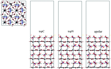
MAPbI3 undergoes a structural phase transition from a cubic to a tetragonal phase at ∼330 K, and it becomes an orthorhombic structure at temperatures below 160 K.43 In the present study, the room temperature tetragonal phase of MAPbI3 was chosen as the model structure for studying the structural and electronic properties in the Li@C60 adsorbed geometries. The computationally optimized cell parameters for the bulk tetragonal phase of MAPbI3 are a = 8.70 Å, b = 8.72 Å and c = 12.83 Å, which are comparable to experimental values.43,44 A typical PSC has asymmetric interfaces ETM/MAPbI3/HTM. Therefore, we consider an asymmetric slab model with the MAI as the top surface layer (facing the vacuum layer) and the PbI layer as the bottom layer of MAPbI3. Here, the MAI-terminated surface is set as the MAPbI3 top surface because this surface facilitates the electron transfer to the C60 ETM.45Many studies have shown that the MA orientation plays an important role in governing the stability and electronic structures of MAPbI3.7,42,45–48 The orientation of the MA molecule has a significant effect on the charge mobility,46 the bandgap change47 and photo-energy conversion efficiencies.7,48 Neutron scattering measurements suggested the formation of either antiferroelectric or ferroelectric domains in these perovskites based on the ordered orientation of MA cations.48 However, the highly disordered orientation of the MA cation at room temperature excludes the possibility of spontaneous polarization in the antiferroelectrics or ferroelectrics due to the ordered orientation of MA cations. In order to take into account the MA orientation effect, we considered three orientations of the MA cation with respect to the top surface as shown in Fig. 1: (i) the topC model with the CH3 group pointing up in all layers, (ii) the topN model with the NH3 group pointing up in all layers, and (iii) the apolar model with half of –NH3 or –CH3 groups pointing up and half pointing down. We first looked at the energetics of the slab models. In Table 1, we summarize the valence band edge (VBE), conductance band edge (CBE), band gap, and the total relative energies of the tetragonal MAPbI3 perovskites with the bare surface. The calculated VBE and CBE for the bare-surface tetragonal MAPbI3 were −4.66 to −5.37 eV and −3.55 to −3.88 eV, respectively. Among them, the topC orientation was the most stable structure with the bandgap of 1.48 eV, in agreement with other works.49 Since the topC model is the most stable structure, we will focus on the tetragonal MAPbI3 perovskites with the topC orientation by introducing a Li+@C60 molecule on various MAPbI3 surfaces: the aboveC, aboveI and bridge positions (see Fig. S1–S3 of the ESI†). In each case, we examined the effect of the Li+ located at the off-central top and bottom inside the C60 cage on the electronic structures of the MAPbI3/Li+@C60 system. Hereafter, we denote the Li+(top)@C60 and Li+(bottom)@C60 molecules as the lithium-ion endohedral fullerene with the Li+ located at the off-central “top” and “bottom” inside the C60 cage, respectively.
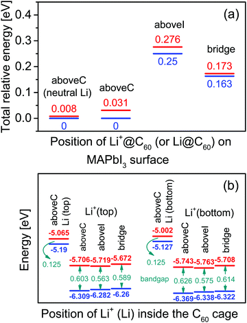
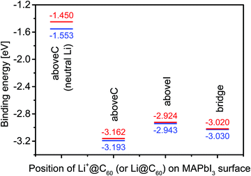
Using the most stable topC model, we introduced one Li+@C60 molecule on the aboveC, aboveI and bridge positions of the MAI surface and performed geometrical optimizations. Fig. 2(a) shows the total energy of the MAPbI3/Li+@C60 system relative to the case with a Li+(bottom)@C60 on the aboveC geometry. The corresponding HOMO, LUMO and band gap are shown in Fig. 2(b). The binding energy of the MAPbI3/Li+@C60 system for three different geometries and the binding energy of the MAPbI3/Li@C60 system for the aboveC geometry are shown in Fig. 3. In general, the stability of the MAPbI3/Li+@C60 system is in the order of a Li+@C60 on the aboveC > bridge > aboveI position. From Fig. 3, the binding energy of the MAPbI3/Li@C60 system also increased in the order of a Li+@C60 on the aboveC > bridge > aboveI geometry, which further confirmed the stability of the MAPbI3/Li+@C60 system. In addition, the MAPbI3/Li+(bottom)@C60 system is energetically more stable than the MAPbI3/Li+(top)@C60 system for the same geometry (see Fig. 2(a)), which is also consistent with the binding energies of the MAPbI3/Li+@C60 system ((see Fig. 3)). Although iodine has a high electronegativity, a Li+@C60 adsorbed on the aboveI position of the CH3NH3PbI3 surface is energetically less favorable as compared to other geometries. Among the MAPbI3/Li+@C60 systems, a Li+(bottom)@C60 absorbed on the aboveC geometry of the MAPbI3 surface is the most stable structure with the strongest binding energy of −3.193 eV (Fig. 3) and the highest bandgap value of 0.626 eV (Fig. 2(b)).
For the MAPbI3/Li+(bottom)@C60 system, the LUMO varies from −5.708 eV to -5.763 eV and the HOMO has a value range from −6.322 eV to −6.369 eV, leading to a bandgap value in the range from 0.575 eV to 0.626 eV. Compared with the MAPbI3/Li+(bottom)@C60 system, the MAPbI3/Li+(top)@C60 system has a slightly lower bandgap ranging from 0.563 eV to 0.603 eV; the LUMO varies from −5.672 eV to −5.706 eV and the HOMO varies from −6.260 to −6.309 eV. It is interesting to note here that the MAPbI3/Li+@C60 system with the aboveC (aboveI) geometry has the largest (smallest) bandgap value of 0.603 (0.563) eV and 0.626 (0.575) eV for the Li+ located at the off-central “top” and “bottom” inside the C60 cage, respectively.
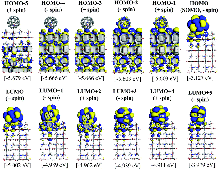
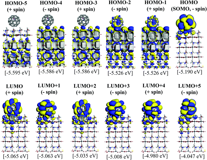
Since the MAPbI3/Li+@C60 system with the aboveC geometry is the most stable structure, we calculated and compared the electronic structures of the MAPbI3/Li+@C60 system with a neutral lithium endohedral fullerene Li@C60 absorbed on the aboveC geometry of the MAPbI3 surface (MAPbI3/Li@C60). The total energy relative to the MAPbI3/Li(bottom)@C60 with the aboveC geometry is depicted in Fig. 2(a), which is very small, i.e. ∼0.008 eV, compared to the MAPbI3/Li+@C60 system. Since the binding energy of the MAPbI3/Li@C60 system is smaller than that of the MAPbI3/Li+@C60 system by over 1.5 eV as shown in Fig. 3, Li@C60 has a great tendency to become a good hole conductor by absorbing a hole. From Fig. 2(b), it is seen that the MAPbI3/Li(top)@C60 has a small band gap of 0.125 eV, which is independent of the off-central position of Li and is smaller than the bandgap of the MAPbI3/Li+@C60 system by a factor of 5. The LUMO and HOMO (SOMO) of the MAPbI3/Li@C60 system are ∼−5.0 eV and ∼−5.1 eV, respectively, which are relatively higher than those of the MAPbI3/Li+@C60 system (see Fig. 7).
When two atoms with opposite charges from two molecular species are in proximity within the sum of their van der Waals (vdW) radii, a non-covalent intermolecular interaction may form between the molecules.50–52 At the interface between the Li+@C60 (or the Li@C60) molecule and the topC-oriented MAPbI3, the C atoms of C60 may interact with the MAPbI3 surface via the I atoms of PbI3 and H (or C) atoms of MA, as shown in Fig. 4 and Fig. S4–S11 (ESI†). The vdW radii of C, H, and I are 1.77 Å, 1.20 Å, and 2.04 Å, respectively.53 This indicates that any C⋯H(–C) distance < 2.97 Å, C⋯C(–H3) distance < 3.54 Å, or C⋯I(–Pb) distance < 3.81 Å may signify a potential interaction between the Li+@C60 and MAPbI3 surface. Based on this criterion, we conducted a simple analysis of the interactions at the MAPb3I/Li+@C60 interface for three different geometries. We also examined the MAPbI3/Li@C60 system with a neutral lithium endohedral fullerene Li@C60 absorbed on the aboveC geometry of MAPbI3. In Table 2, we summarize the atomic distance of selected atoms/molecules (fragments) located at the MAPbI3/Li+@C60 interface, as well as the MAPbI3/Li@C60 interface. A more comprehensive analysis of results can be found in Fig. S4–S11 in the ESI.†
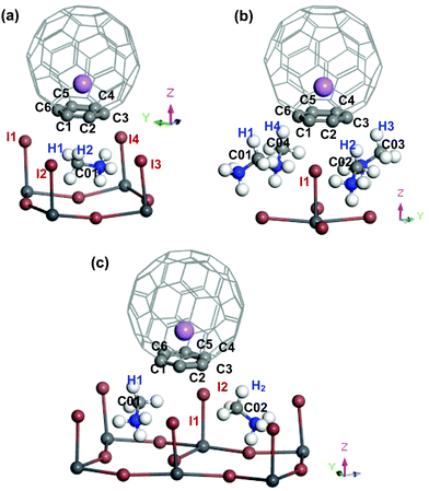 | ||
| Fig. 4 Perspective view (only selected area at the interface between MAPbI3 and Li+@C60) of the topC-oriented MAPbI3 with a lithium endohedral fullerene Li+@C60 on the (a) aboveC, (b) aboveI and (c) bridge position. The Li+ is located at the off-central bottom inside the C60 cage. H, C, N, I, Pb and Li atoms are represented by the white, light grey, blue, brown, dark grey and purple spheres, respectively. Atoms located at the interface between MAPbI3 and C60 are labelled, and their atomic distances within the estimated vdWs atomic radius are summarized in Table 2. | ||
| Surface geometry | C⋯H distance [Å] [vdWs radius <2.97 Å] | C⋯C distance [Å] [vdWs radius <3.54 Å] | C⋯I distance [Å] [vdWs radius <3.81 Å] | |||
|---|---|---|---|---|---|---|
| aboveC (neutral Li) | C5⋯H1 | — (2.944) | ||||
| C1⋯H2 | 2.672 (2.967) | C1⋯C01 | 3.547 (3.538) | C4⋯I4 | 3.782 (3.744) | |
| C2⋯H2 | 2.621 (2.618) | C2⋯C01 | 3.545 (3.544) | |||
| C3⋯H2 | 2.973 (—) | |||||
| aboveC | C1⋯H2 | 2.665 (2.660) | C1⋯C01 | 3.544 (3.538) | C4⋯I4 | 3.787 (3.744) |
| C2⋯H2 | 2.619 (2.612) | C2⋯C01 | (3.544) | |||
| aboveI | C1⋯I1 | 3.411 (3.428) | ||||
| C2⋯I1 | 3.566 (3.580) | |||||
| C3⋯I1 | 3.742 (3.742) | |||||
| C4⋯I2 | 3.762 (3.751) | |||||
| C5⋯I2 | 3.613 (3.604) | |||||
| C6⋯I2 | 3.438 (3.442) | |||||
| bridge | C6⋯H1 | 2.801 (2.791) | C6⋯C01 | 3.457 (3.443) | C2⋯I1 | 3.568 (3.519) |
| C3⋯H2 | 2.990 (2.974) | C3⋯C02 | 3.465 (3.451) | C5⋯I2 | 3.741 (3.703) | |
In the following, we correlate the findings in Table 2 with the stability (Fig. 2(a)) and the binding energy (Fig. 3) of the MAPbI3/Li+@C60 system. From Fig. 2(a), we found that the energetically most stable geometry of the MAPbI3/Li+@C60 system is the aboveC geometry and the next stable geometry is the aboveI position. However, both the aboveC and bridge geometries have the C⋯H(–C), C⋯C(–H) and C⋯I(–Pb) interactions. The results from Table 2 show that the main difference between these two geometries is the C⋯H(–C) atomic distance: the aboveC geometry is in the ranges of 2.612–2.660 Å, whereas it is in the range of 2.791–2.990 Å for the aboveI geometry. This suggests that the C⋯H(–C) interaction, i.e. the π–CH interaction, plays a crucial role in governing the stability of the MAPbI3/Li+@C60 system and the strength of binding between the MAPbI3 and Li+@C60. The MAPbI3/Li+@C60 system with the aboveI geometry is the least stable structure among the three geometries (though they have six C⋯I(–Pb) interactions with highly electronegative iodines), implying that the C⋯I(–Pb) interactions, i.e. the π–I interaction, contributed less as compared with the C⋯H(–C) interactions. All the atomic distances C⋯H(–C), C⋯C(–H) and C⋯I(–Pb) of the MAPbI3/Li+(bottom)@C60 system are shorter than those of the MAPbI3/Li+(top)@C60 system. Therefore, the MAPbI3/Li+(bottom)@C60 system is energetically more stable than the MAPbI3/Li+(top)@C60 system for the structure with the same geometry (Fig. 2(a)). For the same geometry, the binding energy of the MAPbI3/Li+(bottom)@C60 system is also stronger than that of the MAPbI3/Li+(top)@C60 system. Although the MAPbI3/Li@C60 system has a weak binding energy (Fig. 3), both the MAPbI3/Li(top)@C60 system and the MAPbI3/Li(bottom)@C60 system have six bond distances within the vdW interactions (Fig. S4 and S5, ESI†), i.e. three C⋯H(–C) in the range 2.618–2.673 Å, two C⋯C(–H) in the range 3.538–3.547 Å, and one C⋯I(–Pb) in the range 3.744–3.782 Å, with a small energy difference of ∼0.008 eV (Fig. 2(a)). The stability of the Li@C60 molecule is another important factor that contributes to the strength of binding between the MAPbI3 perovskite and the Li@C60 molecule, besides the atomic distances at the MAPbI3/Li+@C60 interface. Although this simple analysis may provide a rough picture of the interaction at the MAPbI3/Li+@C60 (or Li@ C60) interface, it is important to note that the calculated atomic distances using the GGA-PBE may not be accurate. In addition, the lattice dynamics play an important role in determining the structural and electronic properties of these halide perovskites,54–56 and the tetragonal structure of MAPbI3 perovskite at room temperature is strongly anharmonic.57
After gaining an understanding of the correlation between the stability and the vdW interactions at the interface, we investigated the atomic charge distribution at the interface between the MAPbI3 perovskite and Li+@C60 (or Li@ C60). We performed an atomic charge analysis using the geometrical optimized structure of the MAPbI3/Li+@C60 (and MAPbI3/Li@C60) system. We employed the Hirshfeld atomic population analysis, which is based on the electron density at individual atoms.58,59 The Hirshfeld charges of an individual Li@C60 molecule and the MAPbI3 slab are 0.0e and −0.005e, respectively, indicating that they possess neutral charges. On the other hand, the calculated Hirshfeld charge of the individual Li+@C60 molecule was 0.998e, ∼+1e, as expected. Table 3 summarizes the Hirshfeld atomic charges of selected fragments [CH3] and [I] at the MAPbI3/Li+@C60 interface. Q is the charge transferred from [MAPbI3] to [Li+@C60]. [Li+@C60] and [MAPbI3] denote the calculated Hirshfeld fragments of the MAPbI3/Li+@C60 system. Calculated Hirshfeld atomic charges of a MAPbI3 with a neutral lithium endohedral fullerene Li@C60 are for only the aboveC position. A more detailed analysis of the Hirshfeld atomic charges of fragments [CH3], [I], [Li], [Li+], and [C] at the MAPbI3/Li+@C60 interface with the Li+@C60 can be found in Table S2 of the ESI.† From Table 3, the MAPbI3/Li@C60 system also possesses a neutral charge similar to the Hirshfeld charge of the individual Li@C60 molecule and the MAPbI3 slab, as expected. For the MAPbI3/Li+@C60 system, the calculated Hirshfeld charge for all three geometries including the Li+ located at the off-central top and bottom positions inside the C60 cage is ∼+1.0e, which is the same as the isolated Li+@C60 molecule. In the MAPbI3/Li+@C60 system, the amount of charge transfer Q from the MAPbI3 to Li+@C60 increased in the order of bridge > aboveI > aboveC geometry. The most stable MAPbI3/Li@C60 system with the aboveC geometry has the highest amount of charge transfer Q, therefore possessing the strongest binding energy. However, the amount of charge transfer of the MAPbI3/Li+@C60 system with the aboveI position is higher than that of the MAPbI3/Li+@C60 system with the bridge position, though the system with the aboveI position is more stable and possesses stronger binding energy. This is because the charge transfer of MAPbI3 to the Li+@C60 on the aboveI position is facilitated by the iodine, which has a high electronegativity. This was evidenced by the fragment [I1] of the aboveI geometry possessing Hirshfeld charges of −0.169e to −0.177e, whereas fragment [I1] of the aboveC and bridge geometries have the Hirshfeld charges of >−0.2e. This implies that more charges are transferred by fragment [I1] in the MAPbI3/Li+@C60 system with the aboveI position than that of the system with the aboveC or bridge position. Since the MAPbI3/Li@C60 system is neutral, there is almost no transfer of charge Q ∼ 0e.
| Atom/molecule | Surface geometry | |||||
|---|---|---|---|---|---|---|
| aboveC [e] | aboveI [e] | Bridge [e] | ||||
| Li (top) | Li (bottom) | Li+ (top) | Li+ (bottom) | Li+ (top) | Li+ (bottom) | |
| [C01H3] | −0.004 | −0.007 | 0.057 | 0.058 | 0.058 | 0.057 |
| [I1] | −0.205 | −0.211 | −0.169 | −0.177 | −0.213 | −0.218 |
| [Li+@C60] | 0.208 | 0.239 | 0.245 | 0.271 | 0.248 | 0.278 |
| [MAPbI3] | 0.789 | 0.758 | 0.752 | 0.726 | 0.745 | 0.715 |
| MAPbI3/Li+@C60 | 0.997 | 0.997 | 0.997 | 0.997 | 0.993 | 0.994 |
| Q | −0.794 | −0.763 | −0.757 | −0.731 | −0.750 | −0.720 |
| [C01H3] | −0.006 | −0.007 | ||||
| [I1] | −0.212 | −0.211 | ||||
| [Li@C60] | −0.049 | −0.067 | ||||
| [MAPbI3] | 0.046 | 0.064 | ||||
| MAPbI3/Li@C60 | −0.003 | −0.003 | ||||
| Q | −0.051 | −0.069 | ||||
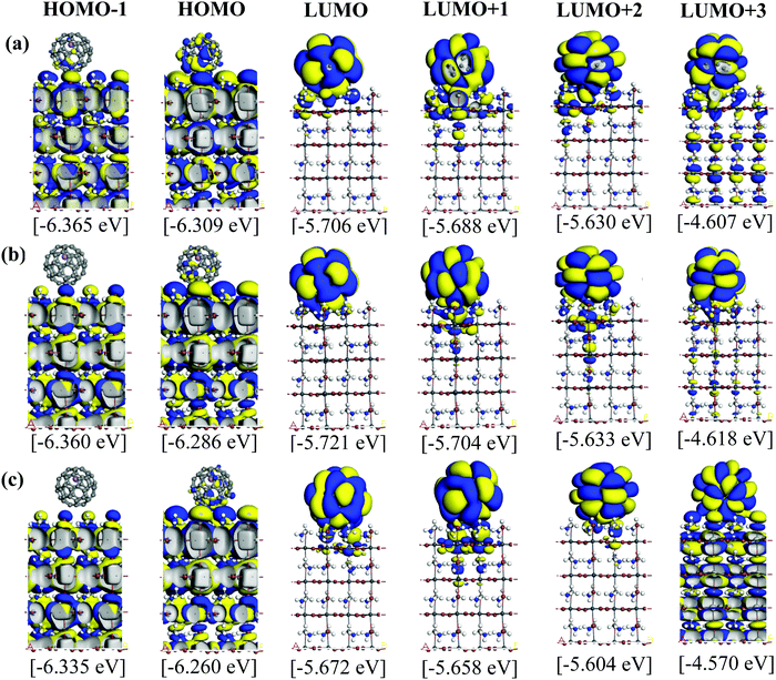
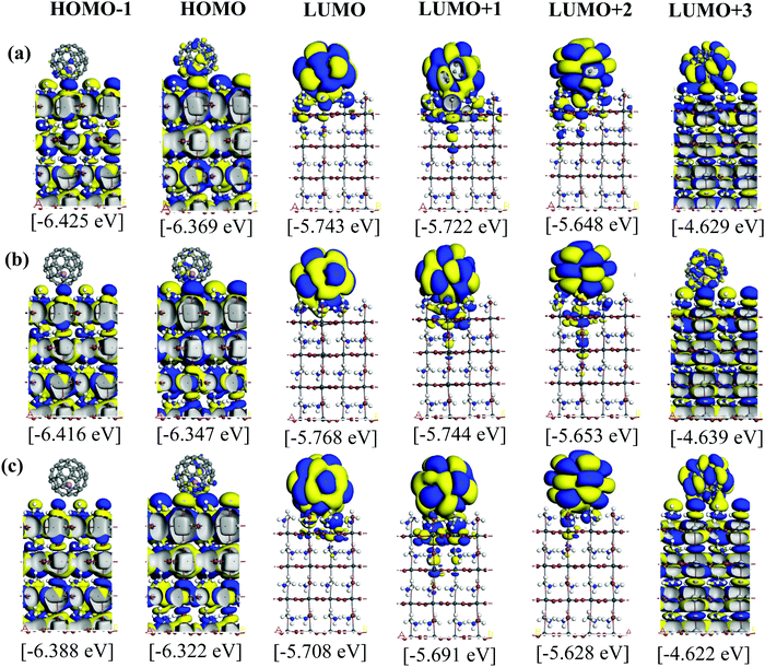
Fig. 5 and 6 illustrate the Kohn–Sham (KS) orbitals and energy eigenvalues of the topC heterojunction with a Li+@C60 on the aboveC, aboveI, and bridge positions for Li+ located at the off-central top and bottom inside the C60 cage, respectively. From the KS orbitals and energy eigenvalues, we find that the energy gap of MAPbI3 is between the HOMO and LUMO+3 levels and amounts to 1.6–1.7 eV. Under light illumination, electrons are excited by this energy and transferred to the ETM, then holes are produced at the HOMO and HOMO−1 levels in the HTM. If there is no other level in the wide band gap of MAPbI3, the created holes can promote the following reactions, similar to the case of TiO2:60
| MAPbI3 (h+) + H2O → MAPbI3 + HO˙ + H+ | (1a) |
| MAPbI3 (h+) + OH− → MAPbI3 + HO˙ | (1b) |
Conclusions
In summary, we have performed first-principles DFT calculations on the electronic structure of MAPbI3/Li+@C60 heterojunctions. Finite slab models of tetragonal MAPbI3 (001) surfaces with MAI terminations were considered. A Li+ (or Li) endohedral fullerene Li+@C60 (or Li@C60) was introduced at different positions on the MAPbI3 surface. We considered the energetically most stable topC geometry of the tetragonal MAPbI3 surface and found that the Li+@C60 was adsorbed at the aboveC position with almost 100% ionization. There was not much difference between the top and bottom positions of Li+ inside C60, but the bottom position was slightly more stable than the top position. In the MAPbI3/Li+@C60 system, the KS wave functions of the HOMO and HOMO−1 levels were spread out in MAPbI3 and those of the LUMO, LUMO+1, LUMO+2 levels were localized in Li+@C60; the energy gap between these levels was 0.6 eV. Thus, in the neutral, spin-polarized MAPbI3/Li@C60 system, the KS wave functions of the HOMO (SOMO, –spin) and LUMO (+spin) levels were both localized in Li@C60 and their energy gap of 0.125 eV was very small. This HOMO (SOMO) level behaves as a hole level when it loses an electron to become Li+@C60. Since there were three almost degenerate LUMO+1 and LUMO+2 levels, it was expected to behave as a good hole conductor. Due to this fact, we concluded that the use of Li+@C60 molecules in place of the bare Li-ions as dopant materials in the MAPbI3 solar cells can prevent degradation. In any case, regardless of the adsorption geometry, our results clearly show the existence of the energetically isolated hole level localized in the Li@C60, which may successfully contribute to the suppression of the oxidation of the MAPbI3 surface. Thus, the present study reveals the stability of the MAPbI3 surfaces.Conflicts of interest
There are no conflicts to declare.Acknowledgements
This work has been supported by Institute for Materials Research, Tohoku University and Dassault Systèmes BIOVIA for the use of supercomputer facilities of IMR and for the ambassador license of BIOVIA. KHChew acknowledges the support from the UM Research Grant (No. GPF079A-2020).References
- A. Kojima, K. Teshima, Y. Shirai and T. Miyasaka, J. Am. Chem. Soc., 2009, 131, 6050 CrossRef CAS.
- M. M. Lee, J. Teuscher, T. Miyasaka, T. N. Murakami and H. J. Snaith, Science, 2012, 338, 643 CrossRef CAS PubMed.
- A. K. Jena, A. Kulkarmi and T. Miyasaka, Chem. Rev., 2019, 119, 3036 CrossRef CAS.
- X. Li, D. Bi, C. Yi, J.-D. Decoppet, J. Luo, S. M. Zakeeruddin, A. Hagfeldt and M. A. Gratzel, Science, 2016, 353, 58 CrossRef CAS PubMed.
- N. J. Jeon, H. Na, E. H. Jung, T.-Y. Yang, Y. G. Lee, G. Kim, H. W. Shin, S. I. Seok, J. Lee and J. Seo, Nat. Energy, 2018, 3, 682 CrossRef CAS.
- A. Y. Alsalloum, B. Turedi, X. Zheng, S. Mitra, A. A. Zhumekenov, K. J. Lee, P. Maity, I. Gereige, A. AlSaggaf, I. S. Roqan, O. F. Mohammed and O. M. Bakr, ACS Energy Lett., 2020, 5, 657 CrossRef CAS.
- K.-H. Chew, R. Kuwahara and K. Ohno, Mater. Adv., 2021, 2, 1665 RSC.
- Y. Fang, C. Bi, D. Wang and J. Huang, ACS Energy Lett., 2017, 2, 782 CrossRef CAS.
- T. Gatti, E. Menna, M. Meneghetti, M. Maggini, A. Petrozza and F. Lamberti, Nano Energy, 2017, 41, 84 CrossRef CAS.
- J. Pascual, J. L. Delgado and R. Tena-Zaera, J. Phys. Chem. Lett., 2018, 9, 2893 CrossRef CAS PubMed.
- E. Castro, J. Murillo, O. Fernandez-Delgado and L. Echegoyen, J. Mater. Chem. C, 2018, 6, 2635 RSC.
- H.-S. Kim, C.-R. Lee, J.-H. Im, K.-B. Lee, T. Moehl, A. Marchioro, S.-J. Moon, H.-B. Robin, J.-H. Yum, J. E. Moser, M. Grätzel and N.-G. Park, Sci. Rep., 2012, 2, 591 CrossRef.
- J. Liu, Y. Wu, C. Qin, X. Yang, T. Yasuda, A. Islam, K. Zhang, W. Peng, W. Chena and L. Han, Energy Environ. Sci., 2014, 7, 2963 RSC.
- R. S. Sanchez and E. Mas-Marza, Solar Energy Mater., Solar Cells, 2016, 158, 189 CrossRef CAS.
- F. Zhao, L. Deng, K. Wang, C. Han, Z. Liu, H. Yu, J. Li and B. Hu, Appl. Mater. Interfaces, 2020, 12, 5120 CrossRef CAS.
- K. Domanski, J.-P. Correa-Baena, N. Mine, M. K. Nazeeruddin, A. Abate, M. Saliba, W. Tress, A. Hagfeldt and M. Grätzel, ACS Nano, 2016, 10, 6306 CrossRef CAS.
- A. K. Jena, Y. Numata, M. Ikegami and T. Miyasaka, J. Mater. Chem. A, 2018, 6, 2219 RSC.
- I. Jeon, H. Ueno, S. Seo, K. Aitola, R. Nishikubo, A. Saeki, H. Okada, G. Boschloo, S. Maruyama and Y. Matsuo, Angew. Chem., 2018, 57, 4607 CrossRef CAS PubMed.
- S. Yun, X. Zhou, J. Even and A. Hagfeldt, Angew. Chem., Int. Ed., 2017, 56, 15806 CrossRef CAS.
- X. Zhou, J. Jankowska, H. Dong and O. V. Prezhdo, J. Energy Chem., 2018, 27, 637 CrossRef.
- C.-J. Yu, J. Phys. Energy, 2019, 1, 022001 CrossRef CAS.
- J. Yin, D. Cortecchia, A. Krishna, S. Chen, N. Mathews, A. C. Grimsdale and C. Soci, J. Phys. Chem. Lett., 2015, 6, 1396 CrossRef CAS PubMed.
- S. Aoyagi, E. Nishibori, H. Sawa, K. Sugimoto, M. Takata, Y. Miyata, R. Kitaura, H. Shinohara, H. Okada, T. Sakai, Y. Ono, K. Kawachi, K. Yokoo, S. Ono, K. Omote, Y. Kasama, S. Ishikawa, T. Komuro and H. Tobita, Nat. Chem., 2010, 2, 678 CrossRef CAS PubMed.
- K. Ohno, Y. Maruyama, K. Esfarjani, Y. Kawazoe, N. Sato, R. Hatakeyama, T. Hirata and M. Niwano, Phys. Rev. Lett., 1996, 76, 3590 CrossRef CAS.
- E. E. B. Campbell, R. Tellgmann, N. Krawez and I. V. Hertel, J. Phys. Chem. Solids, 1997, 58, 1763 CrossRef CAS.
- R. Hatakeyama, Rev. Mod. Plasma Phys., 2017, 1, 7 CrossRef.
- K. Ohno, A. Manjanath, Y. Kawazoe, R. Hatakeyama, F. Misaizu, E. Kwon, H. Fukumura, H. Ogasawara, Y. Yamada, C. Zhang, N. Sumi, T. Kamigak, K. Kawachi, K. Yokoo, S. Ono, Y. Kasama, K. Ohno, A. Manjanath, Y. Kawazoe, R. Hatakeyama, F. Misaizu, E. Kwon, H. Fukumura, H. Ogasawara, Y. Yamada, C. Zhang, N. Sumi, T. Kamigak, K. Kawachi, K. Yokoo, S. Ono and Y. Kasama, Nanoscale, 2018, 10, 1825 RSC.
- H. Ueno, K. Kokubo, Y. Nakamura, K. Ohkubo, N. Ikuma, H. Moriyama, S. Fukuzumi and T. Oshima, Chem. Commun., 2013, 49, 7376 RSC.
- Y. Kawashima, K. Ohkubo and S. Fukuzumi, Chem. – Asian J., 2015, 10, 44 CrossRef CAS PubMed.
- Y. Yamada, A. V. Kuklin, S. Sato, F. Esaka, N. Sumi, C. Zhang, M. Sasaki, E. Kwon, Y. Kasama, P. V. Avramov and S. Sakai, Carbon, 2018, 133, 23 CrossRef CAS.
- H. J. Chandler, M. Stefanou, E. E. B. Campbell and R. Schaub, Nat. Commun., 2019, 10, 2283 CrossRef PubMed.
- K. Miwa, S. Aoyagi, T. Sasamori, H. Ueno, H. Okada and K. Ohkubo, J. Phys. Chem. B, 2021, 125, 918 CrossRef CAS.
- H. Ando and Y. Nakao, Phys. Chem. Chem. Phys., 2021, 23, 9785 RSC.
- B. Delley, J. Chem. Phys., 1990, 92, 508 CrossRef CAS.
- B. Delley, J. Chem. Phys., 2000, 113, 7756 CrossRef CAS.
- B. Delley, in Modern density functional theory: A tool for chemistry in theoretical and computational chemistry. ed. J. M. Seminario and P. Politzer, Elservier, 1995, Vol. 2 Search PubMed.
- E. R. McNellis, J. Meyer and K. Reuter, Phys. Rev. B: Condens. Matter Mater. Phys., 2009, 80, 205414 CrossRef.
- A. Tkatchenko and M. Scheffler, Phys. Rev. Lett., 2009, 102, 073005 CrossRef.
- J. P. Perdew, K. Burke and M. Ernzerhof, Phys. Rev. Lett., 1996, 77, 3865 CrossRef CAS PubMed.
- W.-J. Yin, T. Shi and Y. Yan, J. Phys. Chem. C, 2015, 119, 5253 CrossRef CAS.
- R. A. Jishi, O. B. Ta and A. A. Sharif, J. Phys. Chem. C, 2014, 118, 28344 CrossRef CAS.
- W. Geng, L. Zhang, Y.-N. Zhang, W.-M. Lau and L.-M. Liu, J. Phys. Chem. C, 2014, 118, 19565 CrossRef CAS.
- A. Poglitsch and D. Weber, J. Chem. Phys., 1987, 87, 6373 CrossRef CAS.
- Y. Kawamura, H. Mashiyama and K. Hasebe, J. Phys. Soc. Jpn., 2002, 71, 1694 CrossRef CAS.
- C. Quarti, F. De Angelis and D. Beljonne, Chem. Mater., 2017, 29, 958 CrossRef CAS.
- J. Järvi, J. Li and P. Rinke, New J. Phys., 2018, 20, 103013 CrossRef.
- M. Wierzbowska, J. J. Melendez and D. Varsano, Comput. Mater. Sci., 2018, 142, 361 CrossRef CAS.
- C. Motta, F. El-Mellouhi, S. Kais, N. Tabet, F. Alharabi and S. Sanvito, Nat. Commun., 2015, 6, 7026 CrossRef CAS PubMed.
- V. D’Innocenzo, G. Grancini, M. J. P. Alcocer, A. R. S. Kandada, S. D. Stranks, M. M. Lee, G. Lanzani, H. J. Snaith and A. Petrozza, Nat. Commun., 2014, 5, 3586 CrossRef.
- S. Kawai, T. Nishiuchi, T. Kodama, P. Spijker, R. Pawlak, T. Meier, J. Tracey, T. Kubo, E. Meyer and A. D. Foster, Sci. Adv., 2017, 3, e1603258 CrossRef.
- Z. Han, G. Czap, C.-I. Chiang, C. Xu, P. J. Wagner, X. Wei, Y. Zhang, R. Wu and W. Ho, Science, 2017, 358, 206 CrossRef CAS PubMed.
- S. Kawai, A. Sadeghi, F. Xu, L. Peng, A. Orita, J. Otera, S. Goedecker and E. Meyer, ACS Nano, 2015, 9, 2574 CrossRef CAS.
- S. Alvarez, Dalton Trans., 2013, 42, 8617 RSC.
- F. Brivio, J. M. Frost, J. M. Skelton, A. J. Jackson, O. J. Weber, M. T. Weller, A. R. Goñi, A. M. A. Leguy, P. R. F. Barnes and A. Walsh, Phys. Rev. B: Condens. Matter Mater. Phys., 2015, 92, 144308 CrossRef.
- M. Grechko, S. A. Bretschneider, L. Vietze, H. Kim and M. Bonn, Angew. Chem., Int. Ed., 2018, 57, 13657 CrossRef CAS.
- K. N. Boldyrev, V. E. Anikeeva, O. I. Semenova and M. N. Popova, J. Phys. Chem. C, 2020, 124, 23307 CrossRef CAS.
- R. Sharma, Z. Dai, L. Gao, T. M. Brenner, L. Yadgarov, J. Zhang, Y. Rakita, R. Korobko, A. M. Rappe and O. Yaffe, Phys. Rev. Mater., 2020, 4, 092401(R) CrossRef.
- V. Siva, A. Shameem, A. Murugan, S. Athimoolam, M. Suresh and S. A. Bahadur, Chem. Data Collect., 2019, 24, 100281 CrossRef CAS.
- F. L. Hirshfeld, Theor. Chim. Acta, 1977, 44, 129 CrossRef CAS.
- O. Legrini, E. Oliveros and A. M. Braun, Chem. Rev., 1993, 93, 671 CrossRef CAS.
- H. Okada, H. Ueno, Y. Takabayashi, T. Nakagawa, M. Vrankić, J. Arvanitidis, T. Kusamoto, K. Prassides and Y. Matsuo, Carbon, 2019, 153, 467 CrossRef CAS.
Footnote |
| † Electronic supplementary information (ESI) available. See DOI: 10.1039/d1ma00741f |
| This journal is © The Royal Society of Chemistry 2022 |

