DOI:
10.1039/D1MA00676B
(Paper)
Mater. Adv., 2022,
3, 1713-1728
Potassium–carbonate co-substituted hydroxyapatite compositions: maximising the level of carbonate uptake for potential CO2 utilisation options†
Received
1st August 2021
, Accepted 17th December 2021
First published on 12th January 2022
Abstract
CO2 utilisation is a rapidly growing area of interest aimed at reducing the magnitude of anthropogenic greenhouse gas emissions. We report the synthesis of potassium–carbonate (K–CO3) co-substituted hydroxyapatites with potassium and carbonate contents ranging from approximately 0.4–0.9 wt% and 3.4–13.0 wt% respectively via an aqueous precipitation reaction between calcium hydroxide, phosphoric acid and either potassium carbonate or potassium hydrogen–carbonate. The incorporated carbonate is situated on both hydroxyl and phosphate sites. A subsequent heat treatment in dry CO2 at 600 °C allowed for a K–CO3 co-substituted apatite containing approximately 16.9 wt% CO32− to be prepared, amongst the largest carbonate contents that have been reported for such a material to date. Although this work shows that K–CO3 co-substituted apatites with high levels of carbonate incorporation can be prepared using simple, room temperature, aqueous precipitation reactions with starting reagents unlikely to pose significant environmental risks, testing of these materials in prospective applications (such as solid fertilisers) is required before they can be considered a viable CO2 utilisation option. A preliminary assessment of the effect of potassium/carbonate substitution on the solubility of the as-prepared compositions showed that increasing carbonate substitution increased the solubility.
1. Introduction
The Intergovernmental Panel on Climate Change (IPCC) has projected that if current trends were to continue unabated, greenhouse gases such as CO2 could become so concentrated in the atmosphere that by the year 2100 the global mean surface temperature of the Earth could be more than 4 °C warmer than it was during the pre-industrial era.1 Therefore, immediate action must be taken to reduce the magnitude of anthropogenic greenhouse gas emissions.
One route for achieving this is through the capture of CO2 from large point sources such as fossil-fuel power stations and the subsequent utilisation of this gas in the preparation of functional materials; in addition to potentially permanently fixating the utilised CO2, these products could also lead to a reduction in future CO2 emissions by replacing current more ‘CO2-intensive’ alternatives.2 For example, CO2 could be used as a feedstock in the production of several important chemicals such as methanol, urea and salicylic acid3,4 or reacted with magnesium-rich brines to synthesise inorganic carbonates such as nesquehonite (MgCO3·3H2O) which could find application as a ‘green’ construction material.5 Carbon dioxide could even be reacted with promoter species in the presence of catalysts to form a range of environmentally benign polymers like poly(ethylene carbonate) and poly(propylene carbonate) which could replace conventional plastics.6,7
In a similar manner, CO2 gas could be utilised in the synthesis of a single-phase potassium–carbonate co-substituted hydroxyapatite. As phosphorus and potassium play important roles in plant growth,26–28 we speculate that such K–CO3 co-substituted apatite materials could prove useful as solid fertilisers whilst allowing for captured CO2 to be sequestered either in the solid materials themselves or in the soil to which the apatites are applied. However, careful characterisation of the uptake of CO2 into these materials must be carried out first, to understand e.g. the role of reactant chemistry as a source of CO2, levels of CO2 incorporation that may be feasible, and the role of thermal treatment in a CO2 atmosphere to incorporate additional carbon dioxide. Whilst not yet explored in great detail as a potential CO2 utilisation option, hydroxyapatite has already proven to have application in several fields including aqueous solution remediation, gas detection, agriculture as a fertiliser, ionic conduction and catalysis,14–22 and has been studied as a solid sorbent for carbon capture, with a previous study showing stoichiometric hydroxyapatite can adsorb approximately 0.06–0.07 mmol of CO2 per gram of material when operating at 650–800 °C.23,24
Hydroxyapatite, HA, (Ca10(PO4)6(OH)2) is a widely studied and adaptable calcium phosphate material. Its potential for CO2 utilisation arises from the fact that the HA crystal structure can accommodate a significant quantity of CO2 owing to its ability to substitute both hydroxyl (OH−) and phosphate (PO43−) groups for carbonate (CO32−) ions without compromising the crystal structure of the material. This is achieved through chemical substitution mechanisms, termed A-type and B-type substitution respectively.8 A-type substitution can be attained by heating stoichiometric HA at high temperature in an atmosphere of CO2, where a single carbonate ion replaces two hydroxyl groups to allow overall charge balance to be maintained in accordance with the substitution mechanism shown below:
| Ca10(PO4)6(OH)2 + xCO2 → Ca10(PO4)6(OH)2−2x(CO3)x + xH2O |
Accordingly, A-type carbonate substitution has a theoretical maximum substitution level, achieved once all hydroxyl groups have been replaced with carbonate (
i.e. when
x = 1). The substitution of phosphate groups for carbonate groups can be achieved by the synthesis of a phosphate-deficient apatite (Ca/P > 1.67) with concomitant carbonate substitution introduced through the water used in the aqueous synthesis and/or the calcining/sintering atmosphere.
9 To maintain charge balance, this substitution also requires equimolar substitution of carbonate ions for hydroxyl ions. This substitution mechanism therefore has a limit on the maximum level of carbonate substitution as it relies on the limiting A-type substitution. A common synthesis mechanism for substituting carbonate ions for phosphate groups in the hydroxyapatite lattice is by co-substitution of carbonate with a monovalent cation, typically sodium ions
10,11 but also ammonium
12 or potassium ions.
13 In these examples, some of the calcium ions are substituted for
e.g. sodium ions allowing more carbonate to be incorporated into the structure, according to the charge-balance mechanism:
| (PO4)3− + Ca2+ → (CO3)2− + M+ |
where M
+ could be Na
+, NH
4+ or K
+. This gives the substitution mechanism Ca
10−xM
x(PO
4)
6−x(CO
3)
x(OH)
2. This mechanism focuses on balancing charge on the calcium and phosphate sites of HA, with any carbonate for hydroxyl substitution considered to occur independently. Our previous work showed that high levels of carbonate substitution, approximately 14 and 18 wt%, were achievable when sodium was the monovalent cation involved in the co-substitution, utilising NaCl and CO
2 gas
10 or the more conventional sodium carbonate/sodium hydrogen carbonate reactants,
25 respectively. In these compositions, however, the sodium counter ion does not provide any specific utilisation or benefit for an application of the material. Various methods, such as solid-state reaction,
29 hydrothermal reaction,
30 hydrolysis
31 and ion-exchange,
32 have been used to synthesise K–CO
3 co-substituted apatites with potassium and carbonate contents reported between approximately 0.4–6.9 wt% and 5.3–12.6 wt% respectively. Whyte
et al.13 synthesised a number of K–CO
3 co-substituted hydroxyapatite materials, with substitution values of
x = 0.1–1.0, by aqueous precipitation reaction between calcium hydroxide (Ca(OH)
2), phosphoric acid (H
3PO
4) and potassium hydrogen–carbonate (KHCO
3). These compositions were designed in such a way that potassium and carbonate ions would substitute onto calcium and phosphate sites respectively to such an extent that the overall (Ca + K)/(P + C) molar ratio was 1.67. Although the carbonate content of the samples was not directly measured, FTIR analysis suggested that this increased with
x as intended. The compositions were then heated for two hours at temperatures ranging from 600 to 1050 °C in either air or CO
2 to test their thermal stabilities. The authors observed that the temperature at which the materials decomposed to produce secondary phases of calcium oxide decreased with increasing values of
x (
i.e. with increasing K
+/CO
32− content) and also noted that decomposition occurred at higher temperatures when the samples were heated in an atmosphere of CO
2 compared to when they were heated in air.
The aim of the present work was to investigate the feasibility of using room temperature aqueous precipitation reactions between calcium hydroxide, phosphoric acid and either potassium carbonate or potassium hydrogen–carbonate to prepare several potassium–carbonate (K–CO3) co-substituted apatite materials with high levels of carbonate incorporation. Potassium carbonate or potassium hydrogen–carbonate were chosen to provide the required K+ cations as both of these could theoretically be prepared on an industrial scale by reacting potassium hydroxide with captured CO2, In some cases, this was followed by a heat treatment in a dry carbon dioxide atmosphere to determine what additional carbonate incorporation could be achieved. The prepared materials were characterised using a variety of techniques including powder X-ray diffraction and FTIR spectroscopy. A preliminary study was performed to assess the effect of the carbonate composition on the solubility of the compositions in an acidic buffer, to simulate the conditions of an acidic soil type.
2. Materials and methods
2.1. Synthesis of samples
Potassium–carbonate (K–CO3) co-substituted apatites were synthesised at room temperature by aqueous precipitation reaction between calcium hydroxide (Ca(OH)2, 98% assay, VWR, UK), phosphoric acid (H3PO4, 85% solution in water, Merck) and either potassium carbonate (K2CO3, ≥99% assay, Sigma-Aldrich, UK) or potassium hydrogen–carbonate (KHCO3, 99.7% assay, Sigma-Aldrich, UK), following a method described previously25 that was based on an established precipitation reaction.33 Briefly, two series of compositions were prepared with K2CO3 as the source of potassium ions in Series I and KHCO3 used in Series II. Compositions based on the design formula Ca10−xKx(PO4)6−x(CO3)x(OH)2 were prepared for x = 0–3 and the design compositions are provided in Tables S1 and S2 (ESI†). Precipitation reactions were maintained at an alkaline pH through the addition of 30 ml of aqueous NH3 solution. The H3PO4 solution was added dropwise to the ‘calcium/potassium’ suspension of Ca(OH)2 and K2CO3/KHCO3 over a period of 2 hours, the mixture was aged overnight, filtered and washed with excess water, then the filter-cake was dried in an oven at 90 °C overnight. The dried filter cake was ground to a fine powder which was then subjected to a heat treatment in air at 300 °C for 1 hour using a muffle furnace (Carbolite Gero Ltd, UK), to remove synthesis residuals such as absorbed water; this did not affect the chemical composition of the materials markedly. Powders obtained after this heat treatment were designated ‘as-prepared’. Aliquots (c. 0.5 g) of a selected composition were heated in a tube furnace (Carbolite Gero Ltd, UK) under a dry CO2 gas flow rate of approximately 0.5 dm3 per minute. The temperature in the furnace was ramped from ambient up to the desired heating temperature of 300–700 °C at a rate of 5 °C min−1, held there for one hour and then cooled back to room temperature at the same rate.
2.2. X-ray diffraction analysis
X-ray diffraction (XRD) patterns were collected with a X'Pert Pro diffractometer (PANalytical Ltd, UK), operating at 45 kV and 40 mA with Cu Kα radiation (λ = 1.5418 Å). Data were collected from 15 to 65° 2θ with a step size of 0.013° and a count time per step of 96 s. Crystalline phases present were identified by comparing obtained patterns with PDF files from the ICDD database. The average crystallite sizes were calculated using the Scherrer equation, using the (002) reflection at approximately 25.8° 2θ, and with k = 0.9. A highly crystalline quartz standard was used to compute the instrumental line broadening. Lattice parameters were determined by simple Rietveld refinement of collected XRD data using the PANalytical software package ‘HighScore Plus’.34 Refinements were carried out using the hexagonal space group P63/m using hydroxyapatite data reported by Sudarsanan and Young35 as the initial structural model. Only the background function, scale factor, unit cell parameters and peak shape functions were refined.
2.3. Chemical composition analysis
The Ca/P molar ratio, potassium content and thus the (Ca + K)/P molar ratio of each sample was determined by energy-dispersive X-ray spectroscopy (EDX) using a Gemini SEM 300 field emission SEM (Zeiss, Germany) equipped with an X-ray detector (Oxford Instruments, UK) operating at an accelerating voltage of 15 kV. A powder compact was coated with carbon prior to analysis. For each sample, three measurements were taken and the results reported as an average alongside the standard deviation. The carbonate contents of samples were determined using a LECO CS744 carbon/sulphur analyser (LECO Instruments UK Ltd, UK). For each sample, duplicate measurements were made and the mean value reported alongside the standard deviation. It was assumed that all of the carbon detected by the equipment existed as CO2, which was reasonable as the equipment flooded the combustion chamber with oxygen and also passed the combustion products through an oxidation catalyst.
2.4. FTIR analysis
FTIR spectra were obtained using a Diamond/ZnSe ATR attached to a Spectrum Two™ spectrometer (PerkinElmer, UK). Absorbance spectra were collected at a 2 cm−1 resolution between 4000 and 400 cm−1, averaging 7 scans per sample. Peak deconvolution of the carbonate v2 (850–890 cm−1) and v3 (1300–1600 cm−1) regions and the phosphate v4 (485–700 cm−1) region of the spectra was performed by fitting Gaussian distributions, using the Solver extension in Excel,36 based on peak assignment described elsewhere; a linear background was subtracted prior to deconvolution.
2.5. Dissolution evaluation
The relative solubilities of the different compositions were assessed by incubating as-prepared powder samples (sieved to 53–315 μm size) in an acidic (pH 5.5) buffer solution for 30 minutes and measuring the Ca ion concentration, based on a method described by Mano et al.,37 For each composition studied, 30 mg of sample was incubated in 20 ml of 0.08 M sodium acetate–acetic acid buffer solution, prepared as described elsewhere,38 for 30 minutes at 20 °C, under 150 rpm mixing. A 100 μl aliquot was collected for the measurement of Ca ion concentration in the buffer solution. For each composition 3 replicates were prepared.
The calcium ion concentration was determined using a colorimetric assay based on the ortho-cresolphthalein complexone (o-CPC) method described by Connerty et al.39 Briefly, stock solutions of 1.66 mM o-CPC (64000-1G, Sigma Aldrich, UK), 0.344 M 8-hydroxyquinoline (8-HQ) (H6878-25G, Sigma Aldrich, UK) and 14.8 M ethanolamine (1008451000, Sigma Aldrich, UK) were prepared. A working solution was prepared by combing these three stock solutions to achieve final concentrations of o-CPC and 8-HQ of 0.083 mM and 6.89 mM, respectively, and the concentration of ethanolamine was 0.74 M. A series of Ca2+ standards were prepared by diluting a 1000 ppm Ca2+ standard (21049-100ML, Sigma Aldrich, UK) in water. In a 96 well plate 300 μl of working solution per well was added to 10 μl of each standard/test sample to be measured, the mixture was allowed to react for 5 minutes, then the absorbance at 575 nm was read on a plate reader (BioTek Synergy HT). For each Ca2+ standard duplicate wells were prepared, and for each test sample triplicate wells were prepared.
2.6. Statistical analysis
Comparison of dissolution data from multiple groups (x = 0–2.0) was performed with GraphPad Prism (v5.04, GraphPad Software Inc., USA) using one-way analysis of variance (ANOVA) with a post hoc Tukey's test. For assessment of differences in dissolution data for x = 1.5 from samples synthesised with two different sources of potassium, a t-test was used. Results are reported as mean ± SD. Values of p < 0.05 are considered to be statistically significant.
3. Results and discussion
3.1. As-prepared apatites
3.1.1. X-ray diffraction (XRD) analysis.
XRD patterns of the as-prepared powders of each series are shown in Fig. 1. In Series I (when K2CO3 was used), the compositions were phase-pure apatites by XRD for design substitution values up to and including x = 2.5; all of the reflections in the collected patterns were comparable to the ICDD standard40 for hydroxyapatite. By comparison, the compositions of Series II (when KHCO3 was used) were single-phase apatites only up to x = 1.5. Although this study did not explore the reasons for these differing limits, it would seem reasonable to conclude that this disparity was related to the nature of the potassium reagents themselves. For example, perhaps the lower x-value achieved using KHCO3 was a result of HCO3− ions having substituted into the lattice or (as KHCO3 is significantly less basic than K2CO341) as a result of a lower reaction mixture pH (the pH of the aged reaction mixtures of Series II tended to be up to a full integer lower than their counterparts of Series I). Also, the HA reflections in all of the collected patterns were quite broad which indicated that each hydroxyapatite phase was composed of very small crystallites as would be expected when using an aqueous precipitation synthesis route.42,43 Above these limits of x, an impurity phase of calcite (CaCO3) was observed to form alongside the apatite phase; diffraction peaks attributable to these secondary phases are explicitly marked in Fig. 1. Crystallite sizes were calculated using the Scherrer equation, using the (002) reflection of HA at approximately 25.8° 2θ, and were of the order of 18–29 nm, with some correlation between the design composition and crystallite size, Table S3 (ESI†).
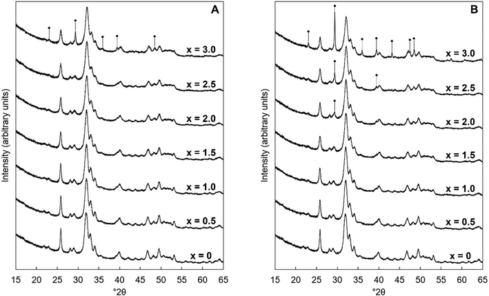 |
| | Fig. 1 Normalised (Imax = 100) XRD patterns between 15–65° 2θ of the as-prepared samples of Series I (A) and Series II (B), where x = 0–3.0 in the design formula Ca10−xKx(PO4)6−x(CO3)x(OH)2. Intense reflections corresponding to impurity phases of calcite are marked using ●. | |
The unit cell parameters of the as-prepared apatites are shown in full in Table S4 (ESI†) and are plotted as a function of the design composition value of x and of the measured carbonate content (described later in Section 3.1.2) of the materials in Fig. 2. In each series, there was a linear contraction in the a lattice parameter and the unit cell volume as the design x-value increased; this linear contraction was also observed when plotted against the measured carbonate contents. There was a linear decrease in the a lattice parameter with increasing measured potassium content for the design compositions between x = 0–1.5, but there was then a loss in any correlation for higher values of Series I (plotted data not shown, but data are provided in Tables S4–S6, ESI†). It is known that B-type carbonate substitution causes the c-axis to expand and the a-axis to contract, whilst A-type carbonate substitution has the opposite effects on the unit cell parameters of HA.8 Therefore, although there was no clear trend in the c unit cell parameter in either series with x/K+/CO32− content, the variations in the a lattice parameter and the unit cell volume suggested that the substitution of carbonate ions on phosphate sites had more of an impact on the hydroxyapatite crystal structure, and thus the dimensions of the unit cell of the as-prepared material, than did the substitution of carbonate ions on hydroxyl sites.
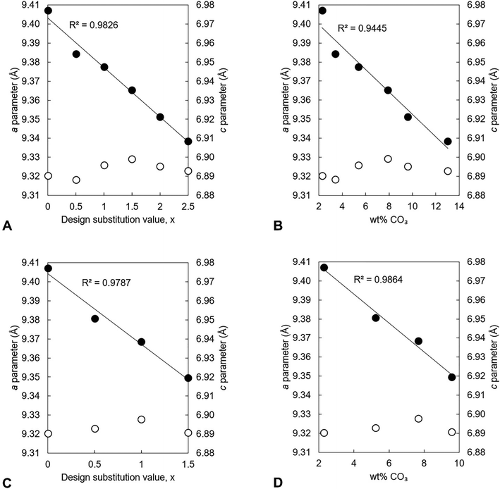 |
| | Fig. 2 The a (●) and c (○) lattice parameters of the as-prepared apatites of Series I (A and B) and II (C and D) plotted as a function of the design substitution value x and the measured carbonate content of these materials. | |
3.1.2. Chemical analysis.
The potassium content as well as the Ca/P and (Ca + K)/P molar ratios of the as-prepared apatites were measured using EDX and their carbonate contents measured using combustion analysis. The results of this analysis are presented in full in Tables S5 and S6 (ESI†) and demonstrate that the chemical composition of these as-prepared materials did not match the design formula. Although potassium ions were indeed present in each of the as-prepared apatites, all of these compositions contained significantly less of these cations than the design amount irrespective of the potassium reagent used in the precipitation reaction, Fig. 3A. In Series I, the measured potassium content of the materials appeared to level out once a certain value of x had been achieved, suggesting that a maximum existed at approximately 0.9 wt% potassium. These lower than expected potassium contents (and the failure to detect any impurity phases using XRD) suggested that, instead of having substituted into the apatite lattice, most of the potassium cations that were added to the reaction mixture had remained in solution and then been lost during the filtration step. Synthesis of sodium/carbonate substituted hydroxyapatite compositions also observed lower than expected levels of sodium substitution, even though increasing amounts of sodium carbonate reactant added resulted in increasing levels of carbonate substitution.25 NH4+ ions are known to be capable of substituting for the calcium ions in hydroxyapatite44 and it could therefore be hypothesised that perhaps some competition existed between K+ ions and NH4+ ions for the open calcium sites. C–H–N analysis was performed on several of the as-prepared apatites but this failed to detect the presence of nitrogen in any of the samples (data not shown). Even so, it is possible that nitrogen existed in very small amounts that could not be detected by the equipment or that this element had been removed during the heat treatment in air at 300 °C and so the synthesis of the x = 0.5 and x = 2.5 apatites of Series I was repeated but this time without adding NH4OH solution to the calcium/potassium suspension. Resulting EDX analysis showed that the exclusion of ammonia solution did not lead to the preparation of apatites with larger potassium contents (Table S7, ESI†) and for x = 2.5 the potassium content was significantly lower when ammonia solution was excluded. While EDX analysis provides a quantitative measure of the trend in increasing Ca/P molar ratio and K content with increasing substitution, additional analytical quantification by spectroscopy methods such as ICP-OES, would provide more precise quantification of the chemical compositions.
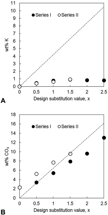 |
| | Fig. 3 Measured potassium (A) and carbonate contents (B), in weight percent, of each series of as-prepared apatites plotted as a function of x. The dashed lines represent the theoretical K+/CO32− content at each value of x, calculated from the design composition formula Ca10−xKx(PO4)6−x(CO3)x(OH)2. | |
In both series, the measured Ca/P molar ratio increased linearly with x. This signalled that the relative content of phosphate ions in the apatites decreased as the design substitution value rose in order to accommodate the substitution of carbonate ions onto B-sites as designed. Whereas the measured Ca/P molar ratios of the apatites prepared using KHCO3 were comparable to the design values, this ratio was invariably smaller than designed in the apatites of Series I. The measured (Ca + K)/P molar ratio of every apatite was lower than designed, a result primarily of the much smaller than expected potassium contents. The carbonate content also increased linearly with increasing x in each series, Fig. 3B. Although the greatest CO32− content (13.0 wt%) was achieved using K2CO3 for x = 2.5, the carbonate contents of Series I were smaller than equivalent design compositions (x values) prepared using KHCO3 and also tended to be smaller than was expected according to the design formula. Nevertheless, these results support the concept that a two-step process could be developed where K2CO3 or KHCO3 is first produced using captured CO2 and then used in the precipitation of highly carbonated K–CO3 co-substituted apatites.
In an effort to increase the maximum degree of carbonation, the synthesis of each series was repeated with CO2 gas bubbled into the H3PO4 solution during the precipitation reaction to create an excess of carbonate ions in the reaction mixture. This gas was bubbled into the H3PO4 solution for 30 minutes prior to this solution being added dropwise to the basic suspension and was maintained until the addition of the H3PO4 solution was complete. The dissolution of CO2 gas, and the subsequent evolution of carbonic acid (H2CO3),45 did not affect the temperature of the H3PO4 solution and by extension the reaction mixture to any significant extent. Whilst the bubbling of this gas into the H3PO4 solution led to a significant increase in the carbonate content of the apatites of Series I at low values of x, its influence diminished markedly as the design substitution value increased (Table 1). For example, the x = 2.5 apatite prepared using K2CO3 and with CO2 gas bubbled into the H3PO4 solution contained 14.1 wt% of carbonate, only marginally larger than the 13.0 wt% seen in the x = 2.5 apatite of Series I. Instead, the carbonate ions that were introduced into the reaction mixture from the potassium reagent itself (in addition to those present from the dissolution of atmospheric CO2) were sufficient to reach the high levels of carbonation that were achieved. The differences in the measured carbonate content in the KHCO3 series, with or without gas added during the reaction, were much smaller, for any x value, than the K2CO3 series; per mole of potassium, the KHCO3 reactant provides more carbonate to the reaction, so this may explain this observation.
Table 1 Carbonate contents of as-prepared K–CO3 co-substituted apatites prepared with K2CO3/KHCO3 and with/without CO2 gas bubbled into the H3PO4 solution during the precipitation reaction, where x = 0–2.5 in the design composition formula Ca10−xKx(PO4)6−x(CO3)x(OH)2. When CO2 gas was used, this gas was bubbled into the H3PO4 solution for 30 minutes prior to this solution being added to the calcium/potassium suspension and continued until the addition of the H3PO4 solution was complete. Other than this alteration, the procedure used to prepare those apatites was identical to that used for the apatites of Series I and II. Analysis was only performed on samples that were single-phase apatites by XRD analysis
| Design x |
K2CO3 |
KHCO3 |
| No CO2 gas (series I) |
CO2 gas |
No CO2 gas (series II) |
CO2 gas |
| 0 |
2.28 ± 0.03 |
3.82 ± 0.01 |
2.28 ± 0.03 |
3.82 ± 0.01 |
| 0.5 |
3.39 ± 0.00 |
5.68 ± 0.04 |
5.23 ± 0.04 |
5.80 ± 0.00 |
| 1.0 |
5.40 ± 0.00 |
7.98 ± 0.04 |
7.68 ± 0.04 |
8.33 ± 0.04 |
| 1.5 |
7.90 ± 0.00 |
8.93 ± 0.04 |
9.58 ± 0.04 |
10.10 ± 0.07 |
| 2.0 |
9.60 ± 0.00 |
11.00 ± 0.07 |
N/A |
N/A |
| 2.5 |
13.03 ± 0.04 |
14.08 ± 0.04 |
N/A |
N/A |
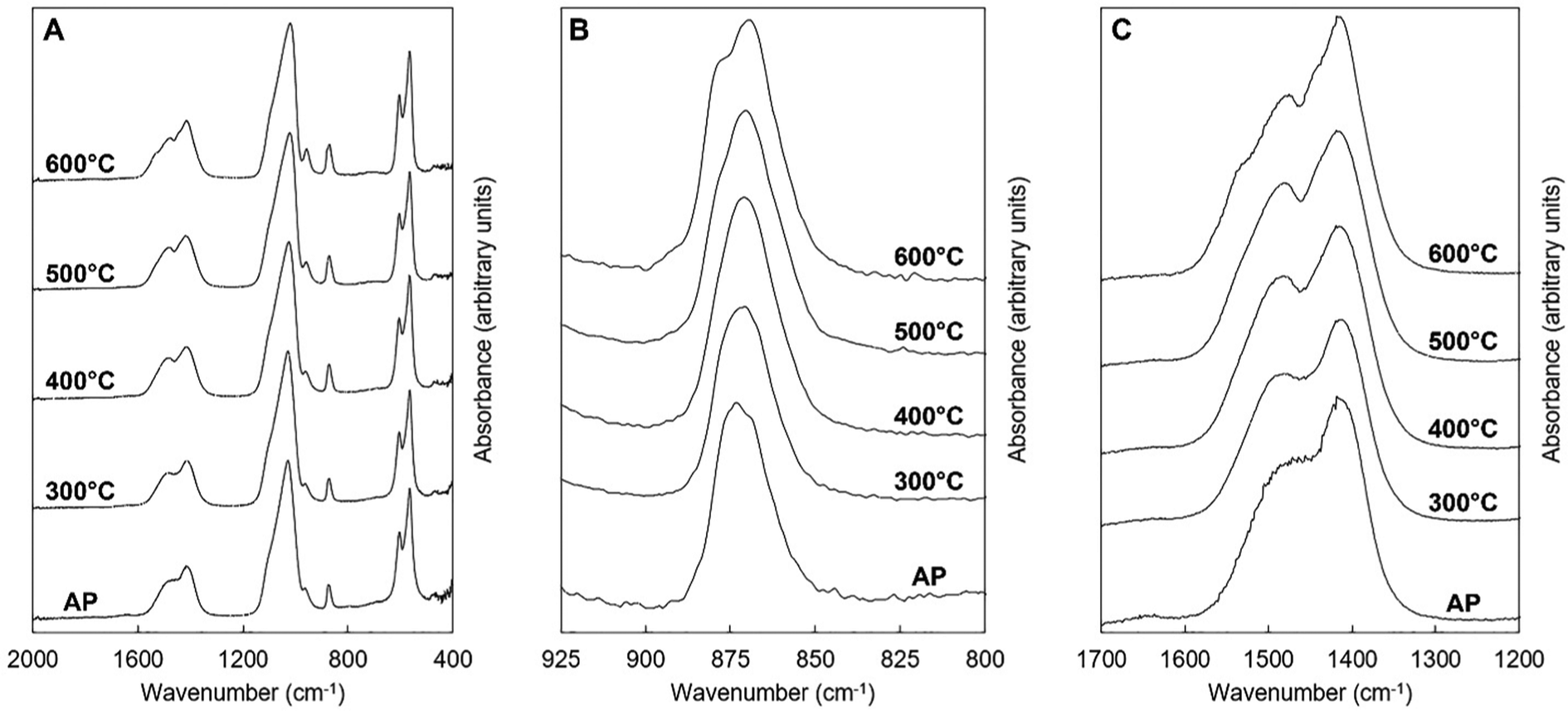
3.1.3. Fourier-transform nfrared spectroscopy (FTIR).
FTIR spectra of the as-prepared K–CO3 co-substituted apatites are presented in Fig. 4. These spectra were comparable to those seen in other studies of apatites prepared by aqueous precipitation reaction.13,46 The four IR-active phosphate vibrations that are characteristic of hydroxyapatite were observed in each spectrum. These appeared to broaden slightly in each series as the design substitution value increased, which may have been due to decreasing crystallite size along the c-axis.47 In addition, a broad band (centred at approximately 1640 cm−1) attributed to the presence of absorbed water48 was visible in each spectrum although this was very weak. The presence of this vibration indicated that neither the oven drying nor the heat treatment in air at 300 °C had fully dried the materials. Vibrations corresponding to the librational and stretching modes of hydroxyl ions were observed in the compositions of both series (at approximately 631 and 3570 cm−1 respectively) at low values of x. Carbonate v2 and v3 bands were also visible in each of these spectra, Fig. 4A, C, D and F, with contributions corresponding to the substitution of carbonate ions on hydroxyl and phosphate sites, consistent with previous studies.8,49–52
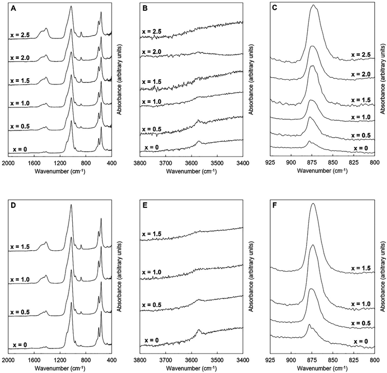 |
| | Fig. 4 Normalised (Amax = 100) FTIR absorbance spectra of the single-phase as-prepared apatites of Series I (A–C) and II (D–F), where x = 0–2.5 in the design formula Ca10−xKx(PO4)6−x(CO3)x(OH)2. | |
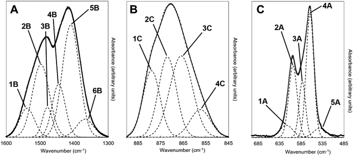
An example of the peak deconvolution of the OH libration and PO4v4 region is shown in Fig. 5A and B for the design composition of x = 1.5 of Series I and Series II, respectively, and the peak positions (numbered from 1a–5a from the highest to the lowest wavenumber) and areas of the phosphate v4 region, including the OH libration, are listed in full in Table S8 (ESI†). Assignment of vibrations in carbonate-containing apatites can be challenging as many parameters that are specific to a given study, such as chemical composition, preparation method, monovalent ion content, thermal treatment temperature and atmosphere can influence the peak positions and intensity of carbonate and phosphate vibrations, so definitive assignment based on literature data must be made with caution. In addition to the expected three PO4 vibrations (peaks 2a, 3a and 4a) at approximately 604–601, 582–576 and 565–561 cm−1, a peak at approximately 545–540 cm−1 (peak 5a) was assigned to HPO4 groups in the apatite structure.53 The peak area of this vibration appeared to decrease slightly with increasing x value in both Series I and II. Peak deconvolution established a peak with decreasing intensity at 631–626 cm−1 (peak 1a) as the value of x increased, which is assigned to hydroxyl libration. The three peaks of the triply degenerate bending mode of the PO4v4 region did not show any strong trend in peak position or peak area with increasing substitution or between the two series, although there appeared to be a slight shift to higher wavenumber of the v4b vibration (peak 3a) from 576 cm−1 for x = 0 up to 582 cm−1 for x = 2.5. The carbonate v2 region produced a very broad band with poor definition of individual vibrations and peak deconvolution required 7–8 peaks to achieve a reasonable fit, although for the highest level of substitution, x = 2.5, Series I, a reasonable fit to 3 peaks was possible. The most intense peaks from the fit were at approximately 877–875, 870–868 and 863–848 cm−1, which are consistent with assignments to A-type (for hydroxyl), B1-type (for phosphate) and B2-type (for phosphate) carbonate substitution, respectively,51 but with a small downshift. A vibration in the region 863–861 cm−1 has been assigned to labile carbonate, HPO4 groups and B2-type carbonate, depending on the composition, so care should be taken in the assignment of this peak in this broad, poorly resolved v2 region. Peak deconvolution of the carbonate v3 regions produced a fit comprising 6 peaks, with examples for the design composition of x = 1.5 of Series I and Series II shown in Fig. 5C and D. The peak positions and areas (arbitrarily numbered from 1b–6b from the highest to the lowest wavenumber) of the carbonate v3 region from the spectra of all single-phase as-prepared compositions in Series I and II are listed in full in Table S8 (ESI†). Three peaks (2b, 3b and 5b) are dominant in the substituted samples, in terms of their peak areas, at 1492–1486 cm−1, 1456–1447 cm−1 and 1412–1401 cm−1; the x = 0 sample produced low intensity vibrations in this region and the peak positions were all closer in peak areas, except the peak at 1417 cm−1 which dominated, and peak positions were typically 10–20 cm−1 higher than the positions of corresponding peaks in the substituted samples. Peak 2b (1492–1486 cm−1) can be assigned to A-type substitution and peak 5b (1412–1401 cm−1) can be assigned to B-type substitution.8,49–52,54–56 Assignment of peak 3b (1456–1447 cm−1) to literature data does not have such a clear consensus, with studies assigning this to both A-type substitution49,51,56 and B-type substitution.50,54,55 In our own recent study, A-type carbonate substituted hydroxyapatites produced peaks at approximately 1532 and 1465 cm−1 with similar peak areas.57 The peak area of the peak in the 1557–1523 cm−1 region in the current study contributes a much smaller amount to the total peak area of the v3 region than the peak at 1456–1447 cm−1, Table S8 (ESI†), suggesting that the latter peak reflects some contribution of A-type carbonate in this region but relates more to B-type carbonate. Weaker bands (peaks 1b, 4b and 6b) at 1557–1523 cm−1, 1424–1419 cm−1 and 1393–1355 cm−1, show some small changes in peak position and area with increasing substitution and between Series I and II, but the most notable was the shift to lower wavenumbers of peak 1b, from approximately 1565 cm−1 for x = 0 to 1523 cm−1 for x = 2.5. Studies on Na-containing apatites have described distinct A-type vibrations, with bands at 1540 and 1449 cm−1 assigned to type-A1, and type A2 to bands at 1569 and 1507 cm−1.58 Peak 1b could be assigned to type A1, with some intensity also within the peak 3b. No clear vibration was identified at approximately 1473 cm−1 which is commonly assigned to B-type substitution, nor a peak at approximately 1565 cm−1 which is commonly assigned to A-type substitution. Yoder et al. produced a potassium–carbonate substituted hydroxyapatite using KHCO3 which had measured potassium (0.51 wt%) and carbonate ion (5.99 wt%) contents that were comparable to x = 0.5 of Series II in this study (Table S6, ESI†) and, without peak deconvolution, identified carbonate vibrations at 1490 and 1540 cm−1 that were assigned to A-type and 1417 and 1451 cm−1 that were assigned to B-type carbonate.54 A band at 1387 cm−1 has been assigned to carbonate in a water compartment, described as within water trapped in pores within grains, or water that is surface adsorbed49 and, as a weak vibration from the presence of water was visible, this is feasible. No vibrations characteristic of calcite or aragonite were observed at ∼713 or 700 cm−1 in any of these spectra, confirming the absence of a calcium carbonate impurity in these samples;59 a peak at 714 cm−1 was observed in the spectrum of the x = 3.0 sample of Series I (data not shown), which showed an impurity of calcite by XRD (Fig. 1). Overall it appears that increasing levels of carbonate and potassium substitution have little impact on the vibrations present and their relative contributions to total carbonate in the as-prepared samples of Series I and II.
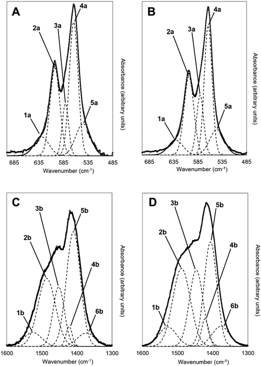 |
| | Fig. 5 Deconvolution of the (A and B) OHL and PO4v4 and (C and D) CO3v3 regions of the FTIR spectra of the as-prepared x = 1.5 compositions for (A and C) Series I (K2CO3) and (B and D) Series II (KHCO3) potassium-carbonate co-substituted samples showing the various vibrations that contribute to the observed spectra; y-axis is an arbitrary scale. Dashed lines correspond to the individual fitted peaks and the solid line is the corresponding model spectra, with the raw data presented as isolated data points. | |
3.1.4. Dissolution evaluation.
To identify if increasing the amount of potassium/carbonate substitution would affect the solubility of hydroxyapatite, powder samples of the Series I as-prepared compositions for x = 0.5 to 2.0, Series II composition with x = 1.5, and an unsubstituted composition (x = 0) were incubated in an acidic (pH 5.5) buffer for 30 minutes, then the Ca2+ ion concentration in the buffer solution measured using a colorimetric assay, Fig. 6. Increasing the design composition in Series I, resulting in an increase in carbonate content, and to a lesser extent an increase in potassium content from x = 0.5 to 1.5 (Tables S5 and S6, ESI†), resulted in an increase in solubility under acidic conditions, with a significant increase in the calcium ion concentration of the buffer solution for design compositions with x = 1.5 and 2.0 (p < 0.05), compared to the unsubstituted x = 0 HA, Fig. 6A. Comparing the two sources of potassium carbonate, the x = 1.5 composition prepared with KHCO3 (Series II) resulted in a higher calcium ion concentration of the buffer solution than the x = 1.5 composition prepared with K2CO3 (Series I), Fig. 6B. The former had a higher measured carbonate content (9.58 wt%) than the latter (7.9 wt%), while both had comparable potassium contents (Tables S5 and S6, ESI†), which supports the view that the carbonate content of the materials correlates with the solubility. Plotting the calcium ion concentration in the buffer solution against the measured carbonate contents of the co-substituted samples from Fig. 3 produced a linear fit with R2 = 0.986, (data not shown). Xiong et al. studied the effect of surface charge of HA nanoparticles on the P release of hydroxyapatite nanoparticles as potential alternatives to triple super phosphate (TSP) fertilisers (monocalcium phosphate) in an acidic soil (pH 4.7) and observed that sustained release of phosphate was dependent on the HA nanoparticles; an electronegative surface charge resulted in the HA nanoparticles having a slower and more sustained release of phosphorus than the TSP fertiliser.22 Our data, while preliminary, suggests that modifying the composition of hydroxyapatite nanoparticles by potassium/carbonate co-substitution is another method to control the solubility, and therefore the phosphorus release, with the additional potential of a concomitant release of potassium ions (albeit it in much smaller quantities than would have been predicted from the design formula).
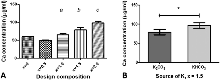 |
| | Fig. 6 Measurement of Ca2+ ion concentration in the sodium acetate–acetic acid buffer after incubation of samples for 30 minutes, for (A) various compositions of x using K2CO3 as the source of potassium, and (B) a composition of x = 1.5 using two different sources of potassium, K2CO3 and KHCO3. Data are presented as the mean ± SD (n = 3) Statistical differences, based on p < 0.05, are noted as: (a) significantly different from x = 0.5; (b) significantly different from x = 0, 0.5 and 1.0; (c) significantly different from x = 0, 0.5, 1.0 and 1.5; and * – significantly different between K source. | |
3.2. Heated apatite(s)
3.2.1. X-ray diffraction (XRD) analysis.
The x = 2.5 apatite of Series I was subjected to several heat treatments in dry CO2 to test if the degree of carbonate substitution in the material could be increased. This composition was chosen as it exhibited the largest carbonate content of all of the as-prepared apatites. XRD patterns of samples heated at 300–700 °C are presented in Fig. 7. Whilst the material remained as a phase-pure apatite after it was heated at 300–600 °C, a secondary phase of calcite was produced after heat treatment at 700 °C. This impurity phase would likely have initially formed as CaO due to the calcium-rich (i.e. Ca/P molar ratio >1.67) nature of the composition,60 but due to the CO2 atmosphere of the heat treatment underwent carbonation to form calcite. The formation of this secondary phase demonstrated that this K–CO3 co-substituted apatite was significantly less thermally stable than stoichiometric HA, which has been shown to be stable in dry or moist air up to approximately 1200 °C.61 This disparity was to be expected and can be explained by examining the differing mechanisms which govern the thermal decomposition of stoichiometric HA and CHAs. Whereas stoichiometric HA is known to decompose as a result of a loss of channel hydroxyl groups above a certain temperature via an oxyhydroxyapatite intermediate, CHAs are understood to decompose upon heating due to the loss of substituted carbonate groups as CO2. Whilst the loss of hydroxyl groups has been reported to begin at approximately 1000 °C in air,62 the loss of carbonate groups from the HA lattice typically begins at much lower temperatures.63,64
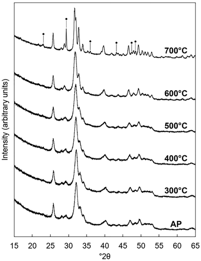 |
| | Fig. 7 Normalised (Imax = 100) XRD patterns of the x = 2.5 composition of Series I as-prepared (AP) and after being heated for one hour in dry CO2 at 300–700 °C. Intense reflections corresponding to an impurity phase of calcite are marked using ●. | |
The lattice parameters of the K–CO3 co-substituted apatites after being heated in dry CO2 at 300–600 °C are shown in full in Table S9 (ESI†) and plotted as a function of the heat treatment temperature in Fig. 8. Both the a and c unit cell parameters (as well as the unit cell volume) of the heated samples tended to be larger than the as-prepared material, with the magnitude of these expansions proportional to the temperature at which the heat treatments were performed. These trends can be explained by considering two scenarios. The first is that CO32− ions had substituted during the heat-treatment exclusively for the relatively smaller hydroxyl groups and oriented mostly parallel to the ab plane, producing the observed expansions in the a parameter and the unit cell volume in accordance with Vegard's law.65 Although expansions in the c unit cell parameter are not usually associated with this type of carbonate substitution, the expansions were relatively small and so could be accounted for by a non-parallel component in the orientation of the substituted carbonate groups. A-type carbonate substitution is usually associated with higher temperature treatments in a CO2 atmosphere for long durations of time, but appreciable A-type substitution can occur at lower temperatures and for shorter time periods.57 Alternatively, carbonate ions may have simultaneously substituted onto both hydroxyl and phosphate sites. Here, the relative expansions of a and c could be used as evidence that the heat treatment had brought about significantly more CO32− substitution on the A-sites than it did the B-sites. Unfortunately, the quality of the diffraction patterns of these nanoscale samples did not allow for a full structure refinement (such as atomic coordinates and site occupancy) to be performed, which is a similar problem to diffraction data from bioapatites.66
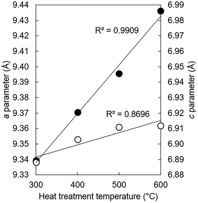 |
| | Fig. 8
a (●) and c (○) unit cell parameters of the x = 2.5 apatite of Series I after this material had been subjected to a heat treatment in dry CO2 at 300–600 °C. | |
3.2.2. Quantitative carbonate analysis.
The results of combustion analysis performed on the x = 2.5, Series I samples that had remained as phase-pure apatites after the heat treatments in dry CO2 are shown in Table 2. Each of the heated samples contained more carbonate than in the as-prepared sample. There was a consistent increase in the carbonate content of the apatite as the temperature increased from 300–600 °C, which suggested that over this temperature range, the carbonate ions previously incorporated into the apatite had been preserved, likely as a result of the CO2 atmosphere in which the heat treatments were performed. After it had been heated in dry CO2 at 600 °C, the apatite material contained approximately 16.9 wt% of carbonate. We believe that this may be the largest carbonate content that has been observed for a single phase K–CO3 co-substituted apatite to date, with other such materials having been reported to contain between 4.95–12.6 wt% of carbonate.29–32,54
Table 2 Measured carbonate content of the x = 2.5 apatite of Series I as-prepared (AP) and after being heated for one hour in dry CO2 at 300–600 °C
| Temperature (°C) |
CO32− content (wt%) |
| AP |
13.03 ± 0.04 |
| 300 |
14.78 ± 0.18 |
| 400 |
16.20 ± 0.07 |
| 500 |
16.88 ± 0.11 |
| 600 |
16.93 ± 0.18 |
Self-evidently, one of the key performance indicators as to the viability of a given CO2 utilisation option is the quantity of carbon dioxide that can be stored. Table 3 demonstrates that the equivalent quantity of carbon dioxide incorporated during the synthesis of this apatite was of the same order of magnitude, but lower than, a number of other widely proposed utilisation options. However, it should be kept in mind that all sectors must be decarbonised if net-zero is to be achieved and it is to be expected that some options will perform better than others with regards to this indicator.
Table 3 A comparison of various CO2 utilisation options in terms of the quantity of carbon dioxide incorporated. The apatites referenced here correspond to the x = 2.5 apatite of Series I, which contained approximately 13 wt% carbonate as-prepared and 16.9 wt% CO32− after being heated for one hour at 600 °C in dry CO2
| Utilisation option |
CO2 utilised (mmol CO2 per g material) |
Ref. |
| As-prepared K–CO3 apatite |
2.3 |
N/A |
| Heated K–CO3 apatite (600 °C in dry CO2) |
2.7 |
N/A |
| Calcium carbonate, CaCO3 |
9.9 |
67
|
| Magnesium carbonate, MgCO3 |
11.8 |
68
|
| Nesquehonite, MgCO3·3H2O |
7.3 |
5
|
| Methanol, CH3OH |
31.1 |
3
|
| Acetic acid, CH3COOH |
16.6 |
3
|
| Benzoic acid, C6H5COOH |
8.2 |
3
|
3.2.3. FTIR analysis of heated samples.
FTIR spectra of the potassium–carbonate co-substituted apatite material (x = 2.5, Series I) after it had been subjected to the heat treatments in dry CO2 are displayed in Fig. 9. The heat treatments caused the broad band at approximately 1640 cm−1, attributable to the presence of absorbed water, to disappear. Additionally, heating the apatite improved the resolution of the contributions corresponding to A and B-type carbonate substitution in the v3 and v2 carbonate regions,52Fig. 9B and C. As for the as-prepared samples, deconvolution of the OHL and PO4v4 region revealed the expected 3 peaks (peaks 2A–4A) related to the PO4 vibrations in apatites, with no significant change in position or relative peak area with increasing heat treatment temperature (Table 4 and the example for 500 °C in Fig. 10C). Increasing the temperature from 300 to 600 °C did, however, affect the OHL vibration (peak 1A) which shifted to lower frequency and eventually could not be fitted in the spectrum from the 600 °C treatment. The peak at 546 cm−1 (peak 5A) in the as-prepared sample, assigned to HPO4, also decreased in intensity as the temperature increased, which would be consistent with loss of hydroxyl groups on heating. Peak deconvolution of the carbonate v3 region of the heated samples showed some clear differences from the as-prepared samples, Table 4 and graphically for the sample heated at 500 °C in Fig. 10A; this also used a six-peak fit (peaks 1B–6B). The main peaks assigned to A-type carbonate substitution in the as-prepared samples, at 1523 and 1492 cm−1 in the x = 2.5 sample (peaks 1B and 2B), remain in all heated samples with comparable contributions (by % peak area) to the total v3 region. The peak at 1401–1410 cm−1 (peak 5B) that was assigned to B-type substitution in the as-prepared samples was again a dominant peak, but appeared to shift considerably to 1418 cm−1 after heating at 600 °C. A peak at 1415–1417 cm−1 (peak 4B) has been assigned to B-type substitution in many studies, so the similarity in peak area of the peak in the 1401–1418 cm−1 region supports that this is a shift as a result of heating to 600 °C. The peak at approximately 1446–1455 cm−1 (peak 3B) that appears in as-prepared samples decreased in contribution with heating. For samples heated at 500–600 °C a peak at 1472–1479 cm−1 appeared which is commonly reported in carbonate-substituted apatites and is assigned to B-type carbonate. This peak increased in relative peak area at the expense of the decreasing peak at 1446–1465 cm−1. While the resolution of the v3 region improves with heating the total band is very broad and in this region, where different studies have assigned vibrations in the region 1445–1455 cm−1 to both A and B-type substitution, care should be taken to assign the different deconvoluted peaks. What is clear is that heating the as-prepared x = 2.5 sample has resulted in some structural change with changes in peak position and relative intensity in the 1400–1480 cm−1 region. From analysis of these heated samples the vibration at 1368–1379 cm−1 (peak 6B) is not likely due to carbonate in a water environment, as proposed by Kaflak et al.;49 the relative peak area % increased slightly after heating in CO2 and the water bending vibration at approximately 1640 cm−1 that was visible in the as-prepared samples disappeared. A band at 1384 and 1386 cm−1 was assigned to A-type carbonate in sodium–carbonate substituted apatites.50 Heating the as-prepared samples also improved the resolution of the carbonate v2 region and the peak deconvolution was successful with 4 peaks, or 3 peaks for the AP and the 300 °C heat treatment, Table 4 and the example for 500 °C in Fig. 10B. Peak 1C at 880–876 cm−1 can be assigned to A-type carbonate substitution and shows a small shift to higher frequency with increasing heat treatment, and between 300 to 600 °C there is only a small decrease in the contribution of this peak to the total peak area of the v2 region. A peak (peak 2C) at 872–868 cm−1 is observed at all conditions and between 400 and 600 °C a second peak (peak 3C) can be fitted at 856–855 cm−1; these can be assigned to B1- and B2-type carbonate, with a small downshift to lower frequency,51 and their summed relative peak area shows a small increase with increasing heat treatment temperature. A peak (peak 4C) at 857–858 cm−1 is present before and after all of the heat treatments and represents about 8–11% of the total peak area. The presence of this peak somewhat mirrors the peak at 1368–1379 cm−1 in the carbonate v2 region, and this could be attributed to a second A2-type carbonate band. It is known that carbonate environments in sodium-bearing carbonate substituted hydroxyapatites are influenced by the presence of the monovalent sodium ions, so the presence of potassium in the materials described here may also have a local influence on the carbonate environments.
 |
| | Fig. 9 Normalised (Amax = 100) FTIR spectra of the x = 2.5 apatite of Series I as-prepared (AP) and after being subjected to heat treatments in dry CO2 at 300–600 °C. | |
Table 4 The deconvoluted peak positions (cm−1) and relative peak areas (%) from the FTIR spectra of the OHL and phosphate v4 region (1A–5A), carbonate v3 (1B–6B) and carbonate v2 (1C–4C) regions of the x = 2.5 apatite of Series I as-prepared (AP) and after being heated for one hour in dry CO2 at 300–600 °C. Peaks are arbitrarily numbered from 1A–5A, or 1B–6B, or 1C–4C, from high to low wavenumbers. Due to rounding peak areas to whole numbers the sum of the peak areas will not always equal 100%
|
|
Peak position (cm−1) and area (%) |
| AP |
300 °C |
400 °C |
500 °C |
600 °C |
| OHL/PO4v4 |
| 1A |
626 (8%) |
627 (8%) |
623 (7%) |
619 (7%) |
N/A |
| 2A |
603 (28%) |
604 (28%) |
604 (28%) |
604 (28%) |
604 (36%) |
| 3A |
582 (14%) |
582 (16%) |
582 (18%) |
582 (17%) |
580 (17%) |
| 4A |
565 (38%) |
564 (39%) |
564 (38%) |
564 (43%) |
564 (43%) |
| 5A |
546 (12%) |
546 (9%) |
547 (8%) |
541 (5%) |
544 (5%) |
|
|
| CO3v3 |
| 1B |
1523 (13%) |
1529 (12%) |
1523 (15%) |
1539 (9%) |
1529 (19%) |
| 2B |
1492 (19%) |
1497 (17%) |
1492 (18%) |
1498 (25%) |
1495 (10%) |
| 3B |
1455 (23%) |
1465 (19%) |
1455 (16%) |
1479 (6%) |
1472 (12%) |
| 4B |
1424 (12%) |
1442 (7%) |
1424 (4%) |
1446 (14%) |
1448 (5%) |
| 5B |
1401 (27%) |
1410 (35%) |
1401 (37%) |
1410 (39%) |
1418 (41%) |
| 6B |
1372 (7%) |
1377 (10%) |
1372 (11%) |
1368 (6%) |
1379 (12%) |
|
|
| CO3v2 |
| 1C |
876 (41%) |
877 (29%) |
878 (29%) |
879 (23%) |
880 (23.5%) |
| 2C |
868 (51%) |
869 (60%) |
871 (26%) |
872 (29%) |
871 (50%) |
| 3C |
N/A |
N/A |
866 (35%) |
866 (37%) |
865 (27.5%) |
| 4C |
858 (8%) |
858 (10%) |
857 (9%) |
857 (11%) |
857 (8%) |
 |
| | Fig. 10 Deconvolution of the (A) CO3v3, (B) CO3v2 and (C) PO4v4 regions of the FTIR spectra of the x = 2.5, Series I potassium–carbonate co-substituted hydroxyapatite sample heated to 500 °C in CO2, showing the various vibrations that contribute to the observed spectra; y-axis is an arbitrary scale. Dashed lines correspond to the individual fitted peaks and the solid line is the corresponding model spectra, with the raw data presented as isolated data points. | |
Estimation of the carbonate content from the FTIR data of the as-prepared compositions and the heat-treated x = 2.5 samples was performed and compared to the carbonate content (wt%) measured from combustion analysis data, Tables 1 and 2. A number of approaches have been reported in the literature for quantifying the carbonate content in apatites from the FTIR data, including determining carbonate to phosphate ratios from peak intensities or from peak areas, using isolated peaks or specific regions, and also using v2 or v3 carbonate regions and v3/v1 or v4 phosphate regions of the spectra.69 As the deconvolution of the carbonate v2 region of the as-prepared samples was limited, and the poorly defined and overlapping v3/v1 phosphate regions results in assumptions being made, the carbonate to phosphate ratios determined were based on (i) the total v3 carbonate peak area divided by the total v4 phosphate peak area excluding the OHL peak, and (ii) the peak intensity ratio (PIR) of the carbonate band at ∼1415 cm−1 (in practise 1401–1418 cm−1) divided by the peak intensity of the v4 phosphate band at ∼604 cm−1.47 The measured carbonate contents (wt%) by combustion analysis of all the as-prepared and heated samples were then plotted against the peak area ratios of the CO3v3 and PO4v4 regions, Fig. 11A, and the peak intensity ratios of the CO3v3 vibration at approximately 1410 cm−1 and the PO4v4 vibration at approximately 603 cm−1, Fig. 11B, with linear fits applied to the data. Both methods provide good linear fits to the data (R2 values of 0.978 and 0.939, respectively), even though this combines data using two different potassium carbonate reactants and also as-prepared and heat treated samples. This confirms that the total carbonate content of samples increases with both increasing substitution design level, and with increased temperature of heat treatment. In terms of the distribution of carbonate ions over hydroxyl and phosphate sites, so A-type and B-type, the ratio of the peak areas assigned in the v2 region is commonly used to describe a B/A ratio, with this being extended when including duplicate bands (B1 and B2, and A1 and A2) have been assigned.51 If the peak at 857 cm−1 is not included, the (B1 + B2)/A1 peak area ratio, based on the assignment described above, shows an increase with increasing heat treatment temperature, from 1.2, 2.1, 2.1, 2.9 and 2.9 for AP, 300, 400, 500 and 600 °C (including the 857 cm−1 peak, so the (B1 + B2)/(A1 + A2) ratio, provides values of 1.0, 1.5, 1.6, 1.9 and 2.2). The increase in carbonate content of the x = 2.5 composition with increasing temperature is therefore associated with a greater amount of that carbonate locating on the B-site. The increase in both unit cell parameters of the heated samples with increasing temperature was supportive of addition of carbonate ions in both hydroxyl and phosphate sites, but the unit cell parameter changes could also be associated with the reduction in the hydroxyl and HPO4 peak intensities observed in the FTIR data, and/or rearrangement of the planar carbonate groups on their respective sites, as the samples are heated. The heated samples do not significantly improve the crystallinity of the samples, with temperatures above 750 °C typically required to achieve this, which limits the analysis of the structure by Rietveld refinement of the diffraction data.
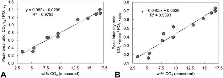 |
| | Fig. 11 Analysis of the FTIR data of samples of potassium–carbonate co-substituted hydroxyapatites. The measured carbonate contents (wt%) by combustion analysis of all the as-prepared and heated samples from this study were plotted against (A) peak area ratios of the CO3v3 and PO4v4 regions (excluding any contribution from an OH vibration at approximately 630 cm−1) and (B) peak intensity ratios of the CO3v3 vibration at approximately 1410 cm−1 and the PO4v4 vibration at approximately 603 cm−1, with linear fits applied to the data. | |
4. Conclusions
K–CO3 co-substituted apatite materials with potassium and carbonate contents that ranged from approximately 0.4–0.9 wt% and 3.4–13.0 wt% respectively were prepared by aqueous precipitation reaction between Ca(OH)2, H3PO4 and either K2CO3 or KHCO3. A subsequent heat treatment in dry CO2 at 600 °C allowed for a potassium–carbonate co-substituted apatite containing approximately 16.9 wt% CO32− to be prepared, believed to be amongst the largest carbonate contents that have been reported for such a material to date. Dissolution experiments showed that the solubility of these materials increased with increasing potassium/carbonate substitution. Whilst this work demonstrates that K–CO3 co-substituted apatites with high levels of carbonate incorporation can be prepared using simple, room temperature, aqueous precipitation reactions with starting reagents unlikely to pose significant environmental risks, comprehensive testing of these materials in prospective applications (e.g. as solid fertilisers) would be required before they can be considered a viable CO2 utilisation option.
Conflicts of interest
The authors have no conflicts to declare related to this study.
Acknowledgements
The authors would like to acknowledge the University of Aberdeen and the Royal Commission for the Exhibition of 1851 for providing financial support as well as Mr Colin Taylor, Mr John Still and Dr Brian Hutton for their assistance in collecting some of the experimental data presented here.
References
-
IPCC, Climate Change 2014: Synthesis Report. Contribution of Working Groups I, II and III to the Fifth Assessment Report of the Intergovernmental Panel on Climate Change [Core Writing Team, ed. R. K. Pachauri and L. A. Meyer, IPCC, Geneva, Switzerland, 2014, p. 151 Search PubMed.
-
IPCC, IPCC Special Report on Carbon Dioxide Capture and Storage. Prepared by Working Group III of the Intergovernmental Panel on Climate Change, ed. B. Metz, O. Davidson, H. C. de Coninck, M. Loos and L. A. Meyer, Cambridge University Press, Cambridge, United Kingdom and New York, NY, USA, 2005, p. 442 Search PubMed.
- M. Aresta and A. Dibenedetto, Utilisation of CO2 as a Chemical Feedstock: Opportunities and Challenges, Dalton Trans., 2007, 2975–2992 RSC.
- E. I. Koytsoumpa, C. Bergins and E. Kakaras, The CO2 Economy: Review of CO2 Capture and Reuse Technologies, J. Supercrit. Fluids, 2018, 132, 3–16 CrossRef CAS.
- J. Morrison, G. Jauffret, J. L. Galvez-Martos and F. P. Glasser, Magnesium-Based Cements for CO2 Capture and Utilisation, Cem. Concr. Res., 2016, 85, 183–191 CrossRef CAS.
- R. Muthuraj and T. Mekonnen, Recent Progress in Carbon Dioxide (CO2) as Feedstock for Sustainable Materials Development: Co-Polymers and Polymer Blends, Polymer, 2018, 145, 348–373 CrossRef CAS.
- M. Tamura, K. Ito, M. Honda, Y. Nakagawa, H. Sugimoto and K. Tomishige, Direct Copolymerization of CO2 and Diols, Sci. Rep., 2016, 6, 24038 CrossRef PubMed.
- R. Z. LeGeros, O. R. Trautz, E. Klein and J. P. Legeros, Two Types of Carbonate Substitution in the Apatite Structure, Experientia, 1969, 25(1), 5–7 CrossRef CAS PubMed.
- I. R. Gibson and W. Bonfield, Novel Synthesis and Characterization of an AB-type Carbonate-Substituted Hydroxyapatite, J. Biomed. Mater. Res., 2002, 59(4), 697–708 CrossRef CAS PubMed.
- D. A. Nowicki, J. M. Skakle and I. R. Gibson, Nano-scale Hydroxyapatite Compositions for the Utilization of CO2 Recovered Using Post-combustion Carbon Capture, J. Mater. Chem. A, 2018, 6(13), 5367–5377 RSC.
- J. A. Stephen, C. Pace, J. M. S. Skakle and I. R. Gibson, Comparison of Carbonate Hydroxyapatite With and Without Sodium Co-Substitution, Key Eng. Mater., 2007, 330-332 I, 19–22 Search PubMed.
- M. Vignoles, G. Bonel and R. A. Young, Occurrence of nitrogenous species in precipitated B-type carbonated hydroxyapatites, Calcif. Tissue Int., 1987, 40(2), 64–70 CrossRef CAS PubMed.
- J. Whyte, D. Hadden, I. Gibson and J. Skakle, Synthesis and Stability of Potassium/Carbonate Co-Substituted Hydroxyapatites, Key Eng. Mater., 2008, 361, 207–210 Search PubMed.
- S. Bailliez, A. Nzihou, E. Beche and G. Flamant, Removal of Lead (Pb) by Hydroxyapatite Sorbent, Process Saf. Environ. Prot., 2004, 82(2), 175–180 CrossRef CAS.
- Y. Feng, J. Gong, G. Zeng, Q. Niu, H. Zhang and C. Niu,
et al., Adsorption of Cd(II) and Zn(II) From Aqueous Solutions Using Magnetic Hydroxyapatite Nanoparticles as Adsorbents, Chem. Eng. J., 2010, 162(2), 487–494 CrossRef CAS.
- L. Luo, Y. Liu, Y. Tan, H. Li, Q. Zhang and K. Li, Room Temperature Gas Sensor Based on Tube-like Hydroxyapatite Modified With Gold Nanoparticles, J. Cent. South Univ., 2016, 23(1), 18–26 CrossRef CAS.
- R. Liu and L. Rattan, Synthetic Apatite Nanoparticles as a Phosphorus Fertilizer for Soybean (Glycine Max), Sci. Rep., 2014, 4, 5686 CrossRef CAS PubMed.
- D. Montalvo, M. J. McLaughlin and F. Degryse, Efficacy of Hydroxyapatite Nanoparticles as Phosphorus Fertilizer in Andisols and Oxisols, Soil Sci. Soc. Am. J., 2015, 79(2), 551–558 CrossRef CAS.
- B. Singh, S. Kumar, B. Basu and R. Gupta, Enhanced Ionic Conduction in Hydroxyapatites, Mater. Lett., 2013, 95, 100–102 CrossRef CAS.
- B. R. De Vasconcelos, L. Zhao, P. Sharrock, A. Nzihou and D. P. Minh, Catalytic Transformation of Carbon Dioxide and Methane Into Syngas Over Ruthenium and Platinum Supported Hydroxyapatites, Appl. Surf. Sci., 2016, 390, 141–156 CrossRef.
- Z. Boukha, M. Kacimi, M. F. R. Pereira, J. L. Faria, J. L. Figueiredo and M. Ziyad, Methane Dry Reforming on Ni Loaded Hydroxyapatite and Fluoroapatite, Appl. Catal., A, 2007, 317(2), 299–309 CrossRef CAS.
- L. Xiong, P. Wang, M. N. Hunter and P. M. Kopittke, Bioavailability and Movement of Hydroxyapatite Nanoparticles (HA-NPs) Applied as a Phosphorus Fertiliser in Soils, Environ. Sci.: Nano, 2018, 5(12), 2888–2898 RSC.
- E. Landi, S. Riccobelli, N. Sangiorgi, A. Sanson, F. Doghieri and F. Miccio, Porous Apatites as Novel High Temperature Sorbents for Carbon Dioxide, Chem. Eng. J., 2014, 254, 586–596 CrossRef CAS.
- O. H. Ojeda-Niño, C. Blanco and C. E. Daza, High Temperature CO2 Capture of Hydroxyapatite Extracted From Tilapia Scales, Univ. Sci., 2017, 22(3), 215–236 CrossRef.
- D. A. Nowicki, J. M. S. Skakle and I. R. Gibson, Maximising Carbonate Content in Sodium-Carbonate Co-substituted Hydroxyapatites Prepared by Aqueous Precipitation Reaction, J. Solid State Chem., 2021, 297, 122042 CrossRef CAS.
- C. Zörb, M. Senbayram and E. Peiter, Potassium in Agriculture– Status and Perspectives, J. Plant Physiol., 2014, 171(9), 656–669 CrossRef PubMed.
- W. T. Pettigrew, Potassium Influences on Yield and Quality Production for Maize, Wheat, Soybean and Cotton, Physiol. Plant., 2008, 133(4), 670–681 CrossRef CAS PubMed.
- L. V. Kochian, Plant Nutrition: Rooting for More Phosphorus, Nature, 2012, 488(7412), 466–467 CrossRef CAS PubMed.
- R. M. Verbeeck, E. A. De Maeyer and F. C. Driessens, Stoichiometry of Potassium-Containing and Carbonate-Containing Apatites Synthesized by Solid State Reactions, Inorg. Chem., 1995, 34(8), 2084–2088 CrossRef CAS.
- T. I. Ivanova, O. V. Frank-Kamenetskaya and A. B. Kol'tsov, Synthesis, Crystal Structure and Thermal Decomposition of Potassium-Doped Carbonated Hydroxyapatite, Z. Kristallogr., 2004, 219(8), 479–486 CAS.
- E. A. P. De Maeyer, R. M. H. Verbeeck and I. Y. Pieters, Effect of K+ on the Stoichiometry of Carbonated Hydroxyapatite Obtained by the Hydrolysis of Monetite, Inorg. Chem., 1996, 35(4), 857–863 CrossRef CAS PubMed.
- E. G. Nordström and K. H. Karlsson, Chemical Characterization of a Potassium Hydroxyapatite Prepared by Soaking in Potassium Chloride and Carbonate Solutions, Bio-Med. Mater. Eng., 1992, 2(4), 185–189 Search PubMed.
- M. Akao, H. Aoki and K. Kato, Mechanical Properties of Sintered Hydroxyapatite for Prosthetic Applications, J. Mater. Sci., 1981, 16(3), 809–812 CrossRef CAS.
- T. Degen, M. Sadki, E. Bron, U. König and G. Nénert, The HighScore Suite, Powder Diffr., 2014, 29(S2), S13–S18 CrossRef CAS.
- K. Sudarsanan and R. A. Young, Significant Precision in Crystal Structure Details: Holly Springs Hydroxyapatite, Acta Crystallogr., Sect. B: Struct. Crystallogr. Cryst. Chem., 1969, B25, 1534–1543 CrossRef.
- J. S. O. Evans and I. R. Evans, Structure Analysis from Powder Diffraction Data: Rietveld Refinement in Excel, J. Chem. Educ., 2021, 98(2), 495–505 CrossRef CAS.
- T. Mano, K. Akita, N. Fukuda, K. Kamada, N. Kurio and K. Ishikawa,
et al., Histological Comparison of Three Apatitic Bone Substitutes with Different Carbonate Contents in Alveolar Bone Defects in a Beagle Mandible with Simultaneous Implant Installation, J. Biomed. Mater. Res., Part B, 2020, 108(4), 1450–1459 CrossRef CAS PubMed.
- A. Ito, Y. Sogo, A. Yamazaki, M. Aizawa, A. Osaka and S. Hayakawa,
et al., Interlaboratory Studies on In Vitro Test Methods for Estimating In Vivo Resorption of Calcium Phosphate Ceramics, Acta Biomater., 2015, 25, 347–355 CrossRef CAS PubMed.
- H. V. Connerty and A. R. Briggs, Determination of Serum Calcium by Means of Orthocresolphthalein Complexone, Am. J. Clin. Pathol., 1966, 45, 290–296 CrossRef CAS PubMed.
- ICDD. PDF Card No. 9-432. Newton Square, Pennsylvania, USA.
- M. Erbeldinger, X. Ni and P. J. Halling, Kinetics of Enzymatic Solid-to-Solid Peptide Synthesis: Synthesis of Z-Aspartame and Control of Acid-Base Conditions by Using Inorganic Salts, Biotechnol. Bioeng., 2000, 72, 69–76 CrossRef.
- S. N. Danilchenko, A. V. Koropov, I. Y. Protsenko, B. Sulkio-Cleff and L. F. Sukhodub, Thermal Behavior of Biogenic Apatite Crystals in Bone: An X-ray Diffraction Study, Cryst. Res. Technol., 2006, 41(3), 268–275 CrossRef CAS.
- M. Sadat-Shojai, M. Khorasani, E. Dinpanah-Khoshdargi and A. Jamshidi, Synthesis Methods for Nanosized Hydroxyapatite With Diverse Structures, Acta Biomater., 2013, 9(8), 7591–7621 CrossRef CAS PubMed.
- Y. Doi, Y. Moriwaki, T. Aoba, M. Okazaki, J. Takahashi and K. Joshin, Carbonate Apatites from Aqueous and Non-Aqueous Media Studied by ESR, IR, and X-ray Diffraction: Effect of NH4 Ions on Crystallographic Parameters, J. Dent. Res., 1982, 61(2), 429–434 CrossRef CAS PubMed.
-
J. Colt, Dissolved Gas Concentration in Water, Elsevier, 2nd edn, 2012 Search PubMed.
- S. Kannan, J. Ventura and J. Ferreira, Synthesis and Thermal Stability of Potassium Substituted Hydroxyapatites and Hydroxyapatite/β-Tricalciumphosphate Mixtures, Ceram. Int., 2007, 33(8), 1489–1494 CrossRef CAS.
- G. Dal Sasso, Y. Asscher, I. Angelini, L. Nodari and G. Artioli, A Universal Curve of Apatite Crystallinity for the Assessment of Bone Integrity and Preservation, Sci. Rep., 2018, 8(1), 12025 CrossRef PubMed.
- J. Reyes-Gasga, E. L. Martínez-Piñeiro, G. Rodríguez-Álvarez, G. E. Tiznado-Orozco, R. García-García and E. F. Brès, XRD and FTIR Crystallinity Indices in Sound Human Tooth Enamel and Synthetic Hydroxyapatite, Mater. Sci. Eng., C, 2013, 33(8), 4568–4574 CrossRef CAS PubMed.
- A. Kaflak, A. Ślósarczyk and W. Kolodziejski, A Comparative Study of Carbonate Bands from Nanocrystalline Carbonated Hydroxyapatites Using FT-IR Spectroscopy in the Transmission and Photoacoustic Modes, J. Mol. Struct., 2011, 997(1–3), 7–14 CrossRef CAS.
- C. H. Yoder, M. M. Bollmeyer, K. R. Stepien and R. N. Dudrick, The Effect of Incorporated Carbonate and Sodium on the IR Spectra of A- and AB-type Carbonated Apatites, Am. Mineral., 2019, 104(6), 869–877 CrossRef.
- M. E. Fleet, Infrared Spectra of Carbonate Apatites: ν2-Region Bands, Biomaterials, 2009, 30(8), 1473–1481 CrossRef CAS PubMed.
- H. Madupalli, B. Pavan and M. M. J. Tecklenburg, Carbonate Substitution in the Mineral Component of Bone: Discriminating the Structural Changes, Simultaneously Imposed by Carbonate in A and B Sites of Apatite, J. Solid State Chem., 2017, 255, 27–35 CrossRef CAS PubMed.
- C. Rey, M. Shimizu, B. Collins and M. J. Glimcher, Resolution-Enhanced Fourier Transform Infrared Spectroscopy Study of the Environment of Phosphate Ions in the Early Deposits of a Solid Phase of Calcium-Phosphate in Bone and Enamel, and Their Evolution with Age. I: Investigations in the v4 PO4 domain, Calcif. Tissue Int., 1990, 46(6), 384–394 CrossRef CAS PubMed.
- C. H. Yoder, N. T. Landes, L. K. Tran, A. K. Smith and J. D. Pasteris, The Relative Stabilities of A- and B-type Carbonate Substitution in Apatites Synthesized in Aqueous Solution, Mineral. Mag., 2016, 80(6), 977–983 CrossRef.
- A. Antonakos, E. Liarokapis and T. Leventouri, Micro-Raman and FTIR Studies of Synthetic and Natural Apatites, Biomaterials, 2007, 28(19), 3043–3054 CrossRef CAS PubMed.
- M. E. Fleet and X. Liu, Coupled Substitution of Type A and B Carbonate in Sodium-Bearing Apatite, Biomaterials, 2007, 28(6), 916–926 CrossRef CAS PubMed.
- D. A. Nowicki, J. M. Skakle and I. R. Gibson, Faster Synthesis of A-type Carbonated Hydroxyapatite Powders Prepared by High-Temperature Reaction, Adv. Powder Technol., 2020, 31(8), 3318–3327 CrossRef CAS.
- M. E. Fleet and X. Liu, Location of Type B Carbonate Ion in Type A–B Carbonate Apatite Synthesized at High Pressure, J. Solid State Chem., 2004, 177(9), 3174–3182 CrossRef CAS.
- N. V. Vagenas, A. Gatsouli and C. G. Kontoyannis, Quantitative Analysis of Synthetic Calcium Carbonate Polymorphs Using FT-IR Spectroscopy, Talanta, 2003, 59(4), 831–836 CrossRef CAS PubMed.
- J. Barralet, J. Knowles, S. Best and W. Bonfield, Thermal Decomposition of Synthesised Carbonate Hydroxyapatite, J. Mater. Sci.: Mater. Med., 2002, 13(6), 529–533 CrossRef CAS PubMed.
- E. Landi, A. Tampieri, G. Celotti and S. Sprio, Densification Behaviour and Mechanisms of Synthetic Hydroxyapatites, J. Eur. Ceram. Soc., 2000, 20(14–15), 2377–2387 CrossRef CAS.
- C. Liao, F. Lin, K. Chen and J. Sun, Thermal Decomposition and Reconstitution of Hydroxyapatite in Air Atmosphere, Biomaterials, 1999, 20, 1807–1813 CrossRef CAS PubMed.
- J. P. Lafon, E. Champion, D. Bernache-Assollant, R. Gibert and A. M. Danna, Thermal Decomposition of Carbonated Calcium Phosphate Apatites, J. Therm. Anal. Calorim., 2003, 72, 1127–1134 CrossRef CAS.
- K. Tõnsuaadu, K. A. Gross, L. Pluduma and M. Veiderma, A Review on the Thermal Stability of Calcium Apatites, J. Therm. Anal. Calorim., 2012, 110, 647–659 CrossRef.
-
A. R. West, Solid State Chemistry and its Applications: Student Edition, John Wiley & Sons, 2nd edn, 2014 Search PubMed.
- C. Meneghini, M. C. Dalconi, S. Nuzzo, S. Mobilio and R. H. Wenk, Rietveld Refinement on X-ray Diffraction Patterns of Bioapatite in Human Fetal Bones, Biophys. J., 2003, 84(3), 2021–2029 CrossRef CAS PubMed.
- R. Chang, S. Kim, S. Lee, S. Choi, M. Kim and Y. Park, Calcium Carbonate Precipitation for CO2 Storage and Utilization: A Review of the Carbonate Crystallization and Polymorphism, Front. Energy Res., 2017, 5, 17 CrossRef.
- J. McCutcheon, I. Power, J. Shuster, A. Harrison, G. Dipple and G. Southam, Carbon Sequestration in Biogenic Magnesite and Other Magnesium Carbonate Minerals, Environ. Sci. Technol., 2019, 53, 3225–3237 CrossRef CAS PubMed.
- E. A. Taylor and E. Donnelly, Raman and Fourier Transform Infrared Imaging for Characterization of Bone Material Properties, Bone, 2020, 139, 115490 CrossRef CAS PubMed.
Footnotes |
| † Electronic supplementary information (ESI) available. See DOI: 10.1039/d1ma00676b |
| ‡ Present address: School of Chemistry, University of St Andrews, North Haugh, St Andrews KY16 9ST, UK. |
|
| This journal is © The Royal Society of Chemistry 2022 |
Click here to see how this site uses Cookies. View our privacy policy here. 
 Open Access Article
 This Open Access Article is licensed under a Creative Commons Attribution-Non Commercial 3.0 Unported Licence
 *a,
Janet M. S.
Skakle
*a,
Janet M. S.
Skakle