
Assessing red blood cell deformability from microscopy images using deep learning†
Erik S.
Lamoureux
ab,
Emel
Islamzada
bc,
Matthew V. J.
Wiens
 d,
Kerryn
Matthews
ab,
Simon P.
Duffy
abe and
Hongshen
Ma
*abdf
d,
Kerryn
Matthews
ab,
Simon P.
Duffy
abe and
Hongshen
Ma
*abdf
aDepartment of Mechanical Engineering, University of British Columbia, 2054-6250 Applied Science Lane, Vancouver, BC V6T 1Z4, Canada. E-mail: hongma@mech.ubc.ca
bCentre for Blood Research, University of British Columbia, Vancouver, BC, Canada
cDepartment of Pathology and Laboratory Medicine, University of British Columbia, Vancouver, BC, Canada
dSchool of Biomedical Engineering, University of British Columbia, Vancouver, BC, Canada
eBritish Columbia Institute of Technology, Burnaby, BC, Canada
fVancouver Prostate Centre, Vancouver General Hospital, Vancouver, BC, Canada
First published on 1st December 2021
Abstract
Red blood cells (RBCs) must be highly deformable to transit through the microvasculature to deliver oxygen to tissues. The loss of RBC deformability resulting from pathology, natural aging, or storage in blood bags can impede the proper function of these cells. A variety of methods have been developed to measure RBC deformability, but these methods require specialized equipment, long measurement time, and highly skilled personnel. To address this challenge, we investigated whether a machine learning approach could be used to predict donor RBC deformability based on morphological features from single cell microscope images. We used the microfluidic ratchet device to sort RBCs based on deformability. Sorted cells are then imaged and used to train a deep learning model to classify RBC based image features related to cell deformability. This model correctly predicted deformability of individual RBCs with 81 ± 11% accuracy averaged across ten donors. Using this model to score the deformability of RBC samples was accurate to within 10.4 ± 6.8% of the value obtained using the microfluidic ratchet device. While machine learning methods are frequently developed to automate human image analysis, our study is remarkable in showing that deep learning of single cell microscopy images could be used to assess RBC deformability, a property not normally measurable by imaging. Measuring RBC deformability by imaging is also desirable because it can be performed rapidly using a standard microscopy system, potentially enabling RBC deformability studies to be performed as part of routine clinical assessments.
Introduction
Red blood cells (RBCs) are highly specialized cells that facilitate tissue respiration by delivering oxygen and removing carbon dioxide.1,2 RBCs transverse through the entire circulatory system approximately every 60 seconds. Their journey includes the microvasculature, where RBCs must deform through capillaries measuring as little as 2 μm in diameter, as well as the inter-endothelial clefts of the spleen measuring 0.5–1.0 μm in diameter.3,4 The loss of RBC deformability, due to pathology, natural aging, or storage in blood bags, reduces the ability of RBCs to circulate and facilitate their removal from circulation by phagocytes in the spleen and the liver.5,6 As a result, there is significant interest in methods for measuring RBC deformability as a potential biomarker for diseases, such as malaria7 and hemoglobinopathies,2,8 or for assessing the quality of donated RBCs for use in blood transfusions.9,10Approaches for measuring RBC deformability can be classified as either flow-based or deformation-based methods. Flow-based methods deform RBCs using fluid shear stress and then measure the resulting shape change. A classical method is ektacytometry, which deforms RBCs using shear flow between two transparent cylinders and then uses optical diffraction to measure the resulting population RBC elongation.11,12 Other flow-based methods deform RBCs using high shear flow through microchannels and then measure the resulting RBC elongation using high speed imaging13,14 or electrical impedance.15 Classical deformation-based methods include micropipette aspiration,16 atomic force microscopy,17 and optical tweezers,18,19 which measure RBC deformability via single cell manipulation, and require complex experimentation, skilled personnel, and specialized equipment.9 Microfluidic deformation-based methods measure RBC deformability via capillary obstruction,20 deposition length in tapered constrictions,21,22 transit pressure through constrictions,7,10,23–27 transit time through constrictions,28–30 and sorting RBCs based on deformability using microfluidic ratchets.31–33 A common challenge for all existing deformability assays is the needs for specialized apparatus and skilled personnel, which limit the ability to translate the technology to clinical settings.34 Additionally, since different assays rely on different underlying principles for measuring RBC deformability, it is often difficult or impossible to compare results across studies.
As an alternative to physical measurement of RBC deformability, cues for biophysical changes in these cells may be obtainable from microscopy images, without the need for highly specialized equipment and personnel. RBCs typically exhibit a highly deformable biconcave discoid morphology, and deviation from this morphology may correspond with changes in cell deformability.35,36 In fact, deep learning methods have been developed to assess changes in RBC morphology during cold storage,37 malaria,38–43 sickle cell disease,44–49 and thalassemia.50–52 However, RBC morphology varies over the life cycle of the cell and this variability may obscure efforts to infer deformability from cell morphology. Furthermore, no specific morphological features can be directly attributed to predictable changes in RBC deformability. We recently developed a microfluidic process for deformability-based sorting of RBCs31–33 as well as a deep learning method to distinguish cell lines based on feature differences imperceptible to human cognition.53 We hypothesized that a combination of these advances could enable the indirect measurement of RBC deformability via cell imaging from optical microscopy to identify image-based cell morphological features associated with deformability.
Here, we investigate the potential to use deep learning to assess RBC deformability based on cell morphological features from brightfield microscopy images. We leverage the ability of a microfluidic ratchet device to sort RBCs based on deformability to generate training sets of RBCs with distinct deformability. We show that the deep learning model can classify RBCs into deformable or rigid fractions using donor dataset sizes ranging from 20![[thin space (1/6-em)]](https://www.rsc.org/images/entities/char_2009.gif) 000 to 70000 images. For a sample of ten donors, who were diverse in terms of blood type and sex, testing classification accuracy ranged from 64–95% with an aggregate mean (± SD) of 81 ± 11%. Using our model to predict donor RBC rigidity scores (RS) was accurate to within a mean of 10.4 ± 6.8% deviation, compared to measurement using a microfluidic device. Our results confirm that RBC deformability can be assessed from microscopy images to potentially simplify the assessment of RBC deformability.
000 to 70000 images. For a sample of ten donors, who were diverse in terms of blood type and sex, testing classification accuracy ranged from 64–95% with an aggregate mean (± SD) of 81 ± 11%. Using our model to predict donor RBC rigidity scores (RS) was accurate to within a mean of 10.4 ± 6.8% deviation, compared to measurement using a microfluidic device. Our results confirm that RBC deformability can be assessed from microscopy images to potentially simplify the assessment of RBC deformability.
Results
Approach
Our experimental approach (Fig. 1) involves first using the microfluidic ratchet device to sort RBCs based on deformability in order to acquire training data for a deep learning image classification model. The microfluidic ratchet device (Fig. 1A) sorts RBCs based on deformability by squeezing cells through a matrix of tapered constrictions (described in Fig. 2). After microfluidic sorting (Fig. 1A), RBCs from each outlet are extracted from the microfluidic device and placed in wells on a 96-well plate (Fig. 1B). These wells are then imaged using an optical microscope in brightfield using a 40× objective (Fig. 1C and D). The microscopy images are processed and segmented into single cell images (Fig. 1E). The resulting datasets are then used to train and test a convolutional neural network for deformability-based image classification (Fig. 1F). Finally, the trained deep learning model is used to classify RBCs in a test set based on deformability. The aggregate RBC deformability is also used to obtain a deep learning-derived deformability profile of the RBC sample (Fig. 1G), which is compared to the profile obtained by microfluidic testing (Fig. 1H). | ||
| Fig. 1 Overall experimental approach. (A) Deformability based sorting using the microfluidic ratchet device. (B) Sorted RBC fractions are transferred to a well plate for imaging. (C) Brightfield imaging using a 40× objective. (D) Example full well image scan. (E) Examples of individual segmented RBCs from donor 1. (F) Structure of the convolutional neural network for image-based cell classification. (G) RBC rigidity score estimated using the CNN. (H) Rigidity score measured by deformability-based cell sorting. | ||
 | ||
| Fig. 2 Microfluidic ratchet sorting device operation. (A) Tapered funnel constrictions allow for unidirectional filtration of RBCs upwards through the constrictions based on their tapered geometry and upward oscillatory flow. Downward oscillatory flow declogs cells that are too rigid to pass through the constrictions. The constriction width for a row of tapers decreases along the flow path (i.e., a < b) to enable deformability-based cell separation. (B) Deformability based sorting occurs in a matrix of tapered constrictions, producing a ratcheting effect. (C) 10× magnification micrograph of the active sorting region where cells are routed to different deformability outlets. (D) 4× magnification micrograph of the entire microfluidic sorting region. RBCs are pictured flowing in an upward diagonal direction from the sample flow inlet on the left, through the matrix of constrictions, and are primarily routed to outlets 3 and 4 on the right. | ||
Deformability based cell sorting
We sorted RBCs based on deformability using the microfluidic ratchet device described and validated previously.7,9,10,16,31–33,54–57 Briefly, RBCs migrate under oscillatory flow through a matrix of micropores with openings ranging from 1.5 μm to 7.5 μm (Table 1). The micropores have the same opening in each row, but progressively smaller openings along each column (Fig. 2A and B). When the cells can no longer transit the micropores along a particular row, they instead flow along the row and are directed into one of 12 outlets (Fig. 2B and C). Oscillatory flow within the device dislodges cells that are blocked by the micropores, ensuring that the cells do not clog the device, allowing for unimpeded operation. In this way, the RBC sample is fractionated based on deformability at a rate of ∼600 cells per minute. More detailed device design and operational details can be found in our previous work.9,55,58| Outlet | 1 | 2 | 3 | 4 | 5 | 6 | 7 | 8 | 9 | 10 | 11 | 12 |
|---|---|---|---|---|---|---|---|---|---|---|---|---|
| Size (μm) | 1.50 | 1.75 | 2.00 | 2.25 | 2.50 | 2.75 | 3.00 | 3.25 | 3.50 | 4.50 | 5.50 | 7.50 |
RBC rigidity score (RS)
After deformability-based sorting, the RBC distribution can be shown as a histogram, where a rightward distribution corresponds to a more rigid RBC sample (Fig. 3A). To compare deformability between samples, the RBC distribution can be shown as a cumulative distribution, which allows us to define a rigidity score (RS) as the outlet number where the cumulative distribution crosses 50%. Fractional outlet numbers can be determined by linear interpolation between data points greater and less than 50% in the cumulative distribution function. RBC samples from different donors showed significant variability in their RS value. For example, from the ten donors in this study the RS ranged from 2.47 to 3.50 (Fig. 3B and C).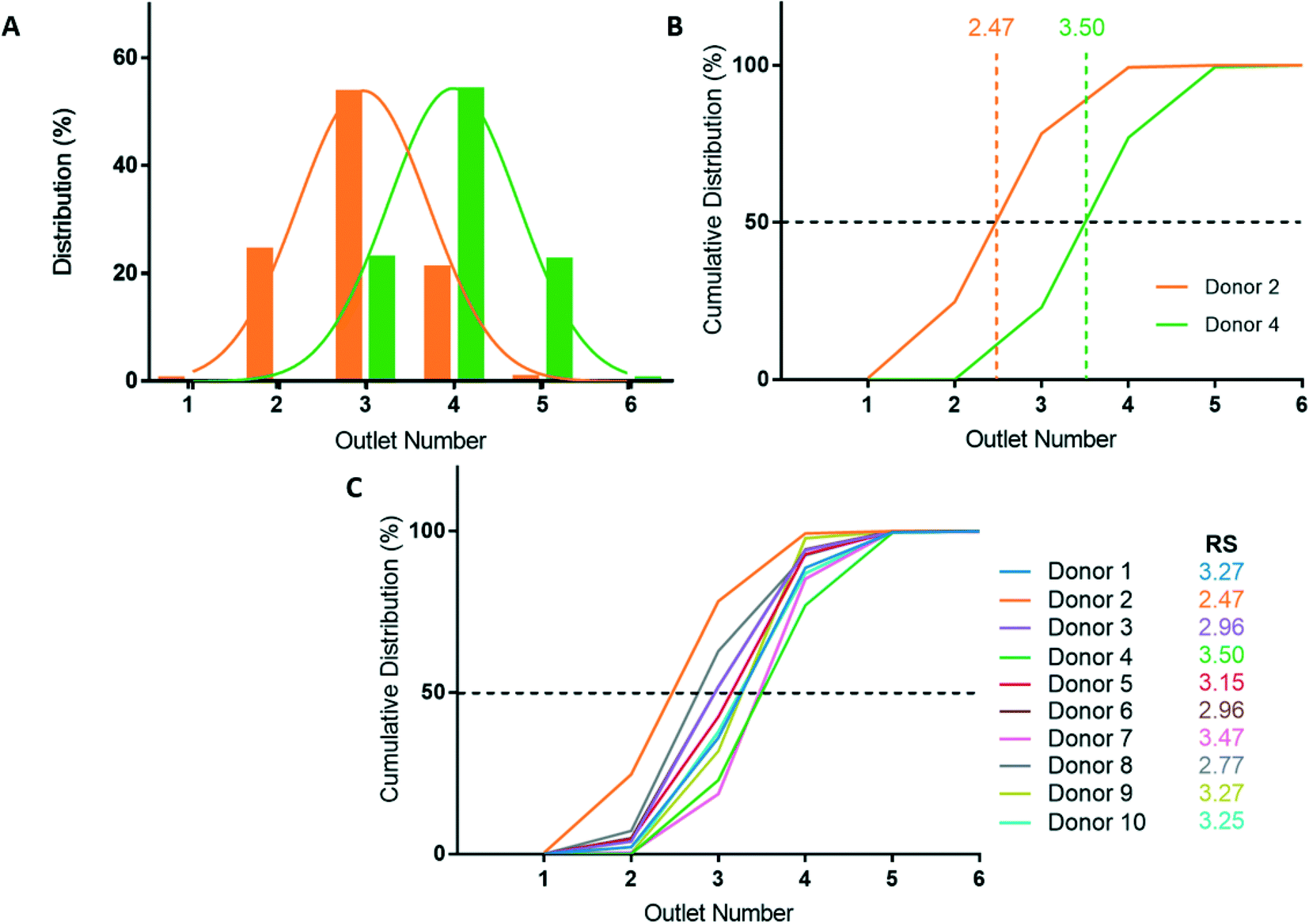 | ||
| Fig. 3 Microfluidic deformability-based sorting results. (A) RBC distribution after deformability-based sorting for select donors. Donor 2 is the most deformable sample (orange) and donor 4 is the most rigid sample (green) of the ten donors analyzed. (B) Cumulative distribution of RBC deformability from donor 2 and 4. The rigidity scores (RS) are measured at the 50% crossover of the cumulative distribution. (C) Cumulative distributions and RS for all ten donors. | ||
Donor-based variability in RBC deformability
Blood donations from ten healthy donors were obtained and RBC samples were sorted based on deformability using the microfluidic ratchet device (Fig. 3C). The donors were diverse in terms of blood type and sex (Table 3). Three blood samples were fresh from a citrate tube (used the day of donation), four were fresh from a blood bag (≤3 days after donation), one was in the second week of blood bag storage, one was in the second week of tube storage, and one was stored in a blood bag for just over 3 weeks (Table 3). Donor RBCs were sorted into outlets 1–6, with the majority (>99%) sorted to outlets 2–5. The cumulative distribution of sorted cells to each outlet is presented in Fig. 3C. These deformability curves and RS are donor-specific and can be reliably measured in repeated experiments using replicate microfluidic devices.9 The donor RS range from 2.47–3.50, which is similar to previous results where the RS ranged from 2.36–3.69 for fresh blood and blood stored for one week could reach elevated RS scores of 3.74.9Optical microscopy imaging for deep learning
After deformability-based cell sorting, the sorted cells are extracted from the microfluidic device by pipetting and placed in 96-well imaging plate (Fig. 1B). Samples from each outlet were split in half and placed in two wells to introduce additional variance in the imaging conditions. These variations include a greater variety of light conditions based on location of cells in the well, cells with different thicknesses of suspension fluid due to its meniscus, and different imaging conditions resulting from differences in focus and exposure time. Full image scans were conducted on each well using a 40× objective and a DS-Qi2 camera on a Nikon Ti-2E inverted microscope, capturing brightfield images of 2424 × 2424 pixels (Fig. 1C and D). Image captures near the edge of the wells were often out of focus and were discarded prior to segmentation.Segmentation
To perform deep learning classification of individual RBCs, we developed a Python program to extract 60 × 60 pixel image patches each containing a single RBC (Fig. 1E). Cells are located using a Sobel operator for edge detection and Otsu multi-thresholding. A centre of mass measurement is conducted to centre the identified cell for image cropping. After the cells are identified and cropped, they proceed through a selection algorithm that keeps images with a single cell centered in the image and rejects images with multiple cells. Further, the resulting selected cropped images are manually audited and any remaining images with multiple cells or those out of focus are removed. This segmentation procedure resulted in datasets containing 20000 to 70000 single cell images for each donor (Table 2). The segmentation process was a significant bottleneck in our analysis process, with the manual data cleaning procedure requiring multiple hours of manual auditing per donor. This bottleneck could potentially be addressed in future iterations of this approach by implementing a U-Net algorithm for pixel-based image segmentation.59
| Donor | Number of images | |||
|---|---|---|---|---|
| Outlet 2 | Outlet 3 | Outlet 4 | Outlet 5 | |
| 1 | — | 14655 |
13831 |
— |
| 2 | 7566 | 14099 |
7195 | — |
| 3 | 7849 | 15352 |
14152 |
3448 |
| 4 | — | 5345 | 3634 | 13482 |
| 5 | — | 10583 |
9879 | — |
| 6 | 7931 | 26514 |
26407 |
10606 |
| 7 | — | 8717 | 25455 |
5938 |
| 8 | 9845 | 18124 |
16776 |
6948 |
| 9 | — | 17094 |
13231 |
— |
| 10 | — | 24276 |
26811 |
18789 |
Network design
We designed a convolutional neural network (CNN) to conduct image feature extraction and classification using the Keras library in TensorFlow (Fig. 1F). For feature extraction, the model utilizes a series of 4 convolutional layers and 3 max pooling layers. We tried a variety of initial kernel sizes as larger sizes capture more robust image features. We settled on an initial convolutional layer kernel size of 7 × 7 as larger sizes did not substantially improve performance. The second convolutional layer kernel size is 5 × 5, and the final two are 3 × 3. Each convolutional layer is followed by batch normalization and ReLU activation. The latter classification section consists of 3 fully connected layers and a final smaller fully connected output layer. The 3 fully connected layers are followed by batch normalization, ReLU activation, and 20% dropout. The output layer uses a SoftMax error function for backpropagation during training. The network utilizes a binary cross-entropy loss function and stochastic gradient descent for optimization. The design of this model was influenced by the AlexNet model architecture60 and deep learning architecture used in previous work in our lab.53 The model was modified for 60 × 60 pixel input images and the number of layers and their sizes were initially iteratively adjusted based on training time and training and validation convergence outcomes.Training and validation
The CNN was trained using single-cell images with true deformability labels determined by microfluidic deformability-based cell sorting. The CNN utilized balanced training classes of 10000 images per class per donor. Cell images were augmented by a random integer multiple of 90-degree rotation to capture different cell orientations and lighting characteristics (Fig. 1E). Classes with fewer than 10000 images were up-sampled, and classes with greater than 10000 images were sub-sampled. The model was trained and validated using five-fold cross validation. The average training accuracies across the five folds for each donor is shown in Table 3 and Fig. 4D. Using the validation and its convergence for each fold, the model was evaluated for hyperparameter tuning iteratively to determine the optimal learning rate, number of epochs, optimizer type, and batch size. Learning rates and number of epochs were donor-specific and ranged from 0.0001 to 0.1 and 25 to 80, respectively. We settled on a stochastic gradient descent (SGD) operator with decay 10−6 and Nesterov momentum 0.9, as an Adam optimizer did not markedly improve outcomes, and the SGD hyperparameters were reliable across all donors. A batch-size of 32 was determined and held for all donors because larger batches can result in reduced ability to generalize, and smaller batches can make learning too stochastic, causing unreliable convergence. There was significant variation in the model's ability to converge during training between different donors, illustrated by the variation in training epochs and learning rates.
| Donor | Blood type | Sex | Storage type, storage time | Outlets | Training accuracyb (%) | Validation accuracyb (%) | Testing accuracyc (%) | Microfluidic RS | Deep learning RS |
|---|---|---|---|---|---|---|---|---|---|
| a Donor Rhesus factor unknown. b Training and validation accuracies indicate the average accuracy across the five cross validation folds. c Additional testing metrics (including precision, recall, F1-score, and ROC AUC) are tabulated in Table S1.† | |||||||||
| 1 | A− | F | Fresh, day 0 | 3, 4 | 92 | 93 | 92 | 3.27 | 3.19 |
| 2 | A+ | M | Tube, day 12 | 2, 3, 4 | 96 | 95 | 95 | 2.47 | 2.66 |
| 3 | O− | M | Bag, day 1 | 2, 3, 4, 5 | 86 | 83 | 84 | 2.96 | 2.84 |
| 4 | A+ | M | Bag, day 2 | 3, 4, 5 | 99 | 96 | 83 | 3.50 | 3.41 |
| 5 | B+ | F | Bag, day 2 | 3, 4 | 86 | 84 | 82 | 3.15 | 3.18 |
| 6 | B+ | M | Bag, day 3 | 2, 3, 4, 5 | 76 | 67 | 64 | 2.96 | 3.05 |
| 7 | B+ | M | Fresh, day 0 | 3, 4, 5 | 85 | 75 | 71 | 3.47 | 3.24 |
| 8 | B+ | F | Bag, day 9 | 2, 3, 4, 5 | 80 | 68 | 66 | 2.77 | 2.75 |
| 9 | Oa | F | Fresh, day 0 | 3, 4 | 96 | 93 | 95 | 3.27 | 3.22 |
| 10 | B+ | F | Bag, day 23 | 3, 4, 5 | 87 | 83 | 81 | 3.25 | 3.11 |
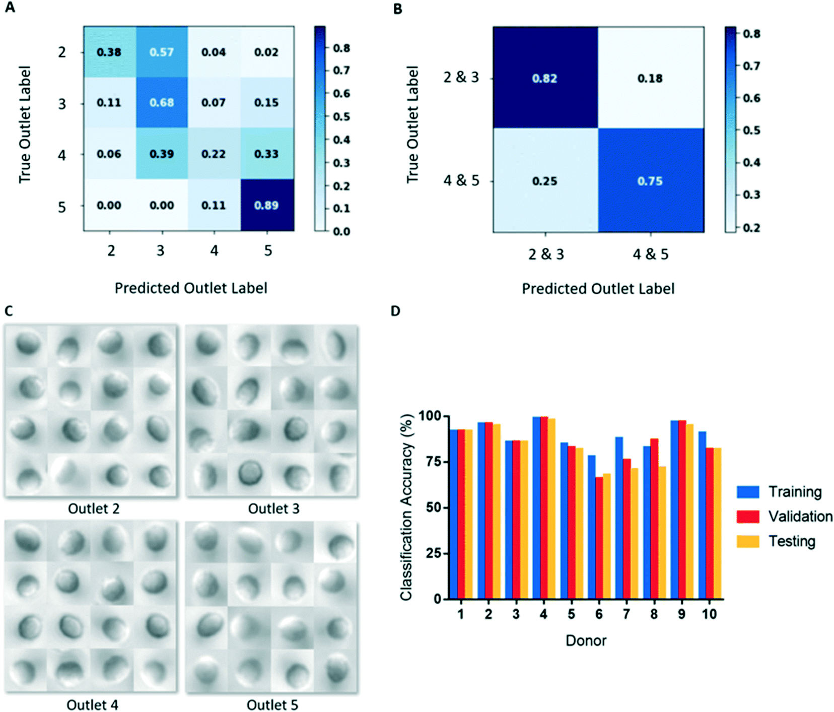 | ||
| Fig. 4 (A) Normalized confusion matrix for donor 3 when RBCs from outlets 2–5 were considered as separate classes. (B) Normalized confusion matrix for donor 3 when RBCs from outlets 2 and 3 (deformable) were pooled into a single class, and RBCs from outlets 4 and 5 (rigid) were pooled into a single class. Classification accuracy is greatly increased with outlets pooled. (C) Example images from outlets 2–5 for donor 6. There does not seem to be obvious visual differences in the RBCs from different outlets. (D) Image classification training, validation, and testing accuracies for all donors. Training and validation accuracies are averaged over the five folds. | ||
Classification
We initially used our CNN to classify cells from microscopy images based on the outlet they were sorted to. However, classifying cells in this manner resulted in poor classification accuracies (Fig. 4A). This result likely derives from there being substantially fewer single cell images from outlets 2 and 5, compared to outlets 3 and 4 (Table 2). To create balanced classes of 10000 images, substantial up-sampling was performed on cells from outlets 2 and 5, requiring many repeated cells. As a result, the variety of cell images seen by the model for these classes were significantly limited. Interestingly, more misclassification occurred between adjacent outlets (Fig. 4A), indicating that the model was learning some common deformability-based cell features.
To improve our classification accuracy, we collapsed the image data from outlets 2 and 3 together and outlets 4 and 5 together to create classes of deformable and rigid cells. By collapsing the classes in this manner, the datasets are more robust as additional cell images are available for augmentation, which required less up-sampling. This binary classification method resulted in substantially improved deformability image predictions (Fig. 4B). An additional advantage of this binary classification method is that inter-donor comparisons are more appropriate as all donors have cells sorted to outlets 3 and 4, but not all have cells sorted to outlets 2 or 5. Since differences in deformability is not a feature that can be easily discerned by a human observer, a large and robust dataset is required for training and testing (Fig. 4C). Using this classification scheme, training accuracies ranged 76–99% and final validation accuracies ranged 67–96%, shown in Table 3 and Fig. 4D.
Testing
The testing datasets are comprised of 20% of the overall segmented data and were separated from the training and validation sets prior to augmentation. This process ensured that there are no cell image repeats between the training and testing sets. For each donor, the images were augmented using the same method used in training and were up-sampled or down-sampled to obtain balanced testing sets of 2000 images per class. Among our donor population, we observed testing accuracies ranging 64–95% with an aggregate mean (± SD) of 81 ± 11% (Table 3 and Fig. 4D). For each donor, we observed that testing accuracy corresponded well with validation accuracy. Additional testing metrics, including precision, recall, F1-score, and ROC AUC can be found in Table S1.†Saliency maps
A key consideration for image classification using deep learning is whether classification was driven by imaging artifacts, such as lighting, sample preparation, image acquisition parameters, and position in the imaging well.61 To resolve this potential issue, we generated saliency maps to assess if the model learned relevant cell morphological features. A saliency map is a visual representation of the spatial support of a particular class to indicate which pixels in a given image had the greatest effect on the classification probability.62 As shown in Fig. 5, the saliency map shows that pixels having the most influence on classification corresponded to those clustered around the cell itself, especially distinct cell features, rather than surrounding regions. This result confirms that our model is classifying RBC deformability based on cell morphological features.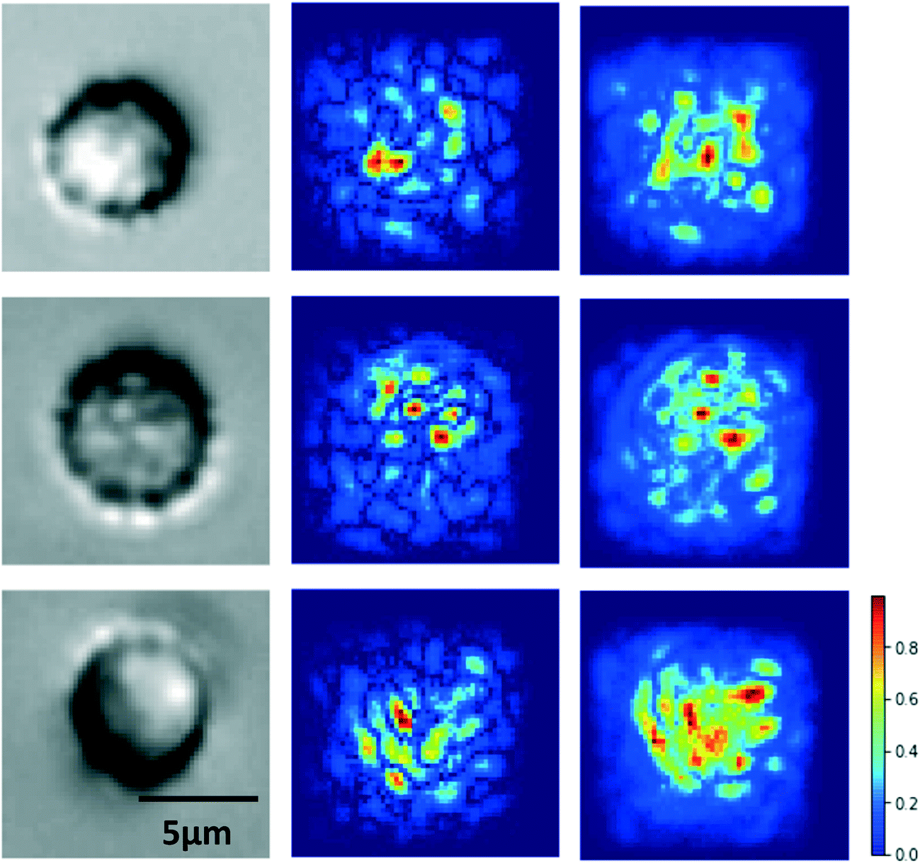 | ||
| Fig. 5 Original images (left), saliency maps (centre), and saliency maps with smoothing (right) of randomly sampled RBCs from donor 4. The saliency map indicates the strength of pixel contributions to the final classification output by the CNN. Warmer colours indicate greater contribution and cooler colours indicate lesser contribution. | ||
Model performance analysis
To further confirm the model performs image classification using cellular features and is not strongly influenced by artifacts, we investigated how classification accuracy varies with reduced imaging resolution. Images were down-sampled from 60 × 60 pixel images to mimic imaging at lower resolutions. Classification accuracy were found to reduce predictably with increased down-sampling (Fig. S3†).We further investigated how classification accuracy varies with reduced training data. Classification accuracy were found to decrease predictably with reduced training data (Fig. S4†). Specifically, our results indicate that ideally >5000 images per class are required to obtain robust classification accuracy.
Finally, we performed a Hough circle transform analysis on cells from different deformability outlets to investigate whether deformability could be determined from planar cell size. We found planar cell size were invariant to cell deformability as determined by sorting, but interestingly, there were statistically significant differences in cell size between donors, which confirmed the validity of our Hough circle transform analysis (Fig. S2†).
Using deep learning to determine rigidity scores of RBC samples
By classifying RBCs into deformable and rigid fractions, we can use this result to estimate the RS for each RBC sample. RBCs classified as deformable and rigid classes are assigned to outlet 3 and 4, respectively. This scheme is justified for the ten donors studied here since the vast majority (86%) of cells from all these donors were sorted into outlets 3 (39%) and 4 (47%), with the reminder sorted into outlets 2 (5%) and 5 (9%). This approach also ensured the RS calculations are consistent for all donors as not every donor had cells sorted to outlets 2 or 5, but all donors had cells sorted to outlets 3 and 4. After classification, the RS is then calculated as before by linearly interpolating the cumulative distribution deformability curve to find the outlet number at the 50% crossover frequency. Assigning cells from outlets 2 and 3 to outlet 3, outlets 4 and 5 to outlet 4 can potentially overestimate the RS for deformable samples and underestimate the RS for rigid samples, but this error is small and systematic since the majority of the RBCs from healthy donors are sorted into outlets 3 and 4.Comparing the cumulative distributions and RS obtained by cell sorting using the microfluidic ratchet device with the RS estimated by deep learn showed a strong agreement (Fig. 6). Specifically, the measured and estimated RS values deviated between a minimum 0.02 (donor 8) to a maximum 0.23 (donor 7) with a mean of 0.10 ± 0.07. Using the potential deep learning RS range between 2.50 and 3.50, the resulting mean percent deviation between the deep learning estimated RS and the microfluidic RS across the ten donors is 10.4 ± 6.8%. Previous work with this microfluidic device has shown a standard deviation for RS of 0.17 across five different tests on the same sample.9 Expressed differently, this RS deviates by 13.8%, relative to the RS range across all donors in that work, indicating the level of deviation seen here is within acceptable variation in RS resulting from random sampling and manufacturing. Furthermore, we plotted the RS acquired by deep learning against RS acquired by microfluidics for the ten donors and found a high degree of correlation between the two methods (Fig. 6K), with a Pearson's correlation of r = 0.94 and p < 0.0001.
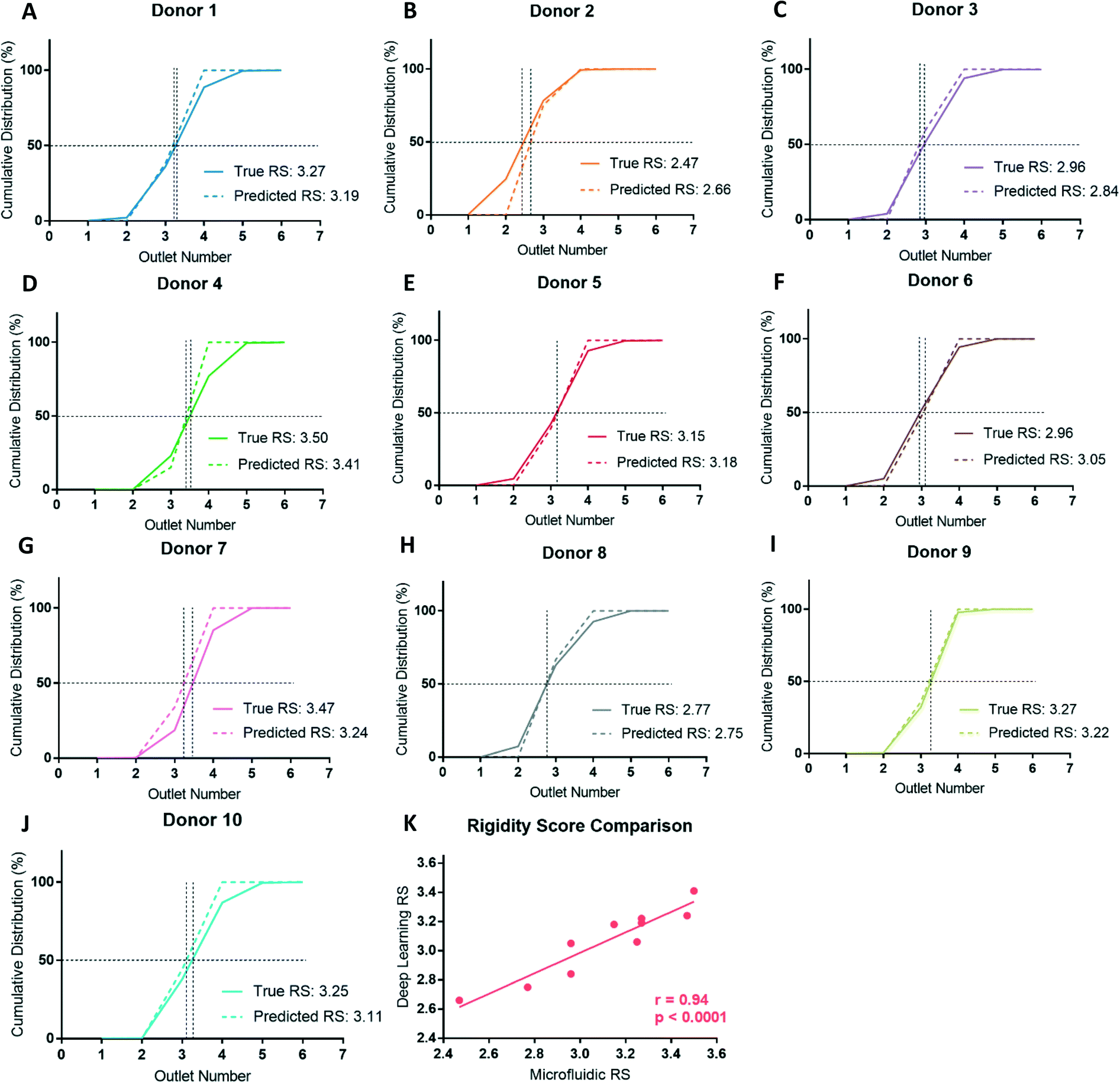 | ||
| Fig. 6 (A–J) Comparison of microfluidic (solid lines) and deep learning (dashed lines) derived RBC deformability cumulative distributions and RS for all ten donors. (K) Relationship between rigidity scores determined by microfluidics and deep learning methods for all ten donors. The deep learning RS values are strongly correlated to the microfluidic RS values (r = 0.94) and this relationship is statistically significant (p < 0.0001). | ||
To assess whether cell sorting using the microfluidic ratchet device may have altered the RBCs, we used the donor-specific trained CNN to classify unsorted cells from donor 2, 3, and 4. This test also assessed the model's generalizability by applying a testing dataset acquired in a separate experimental procedure from the training data. Donors 2, 3, and 4 were selected for assessment as these donors represent the full range of donor RS: donor 2 is most deformable (RS = 2.47), donor 3 is in the middle (RS = 2.96) and donor 4 is the most rigid (RS = 3.50). As before, the cumulative distribution and RS obtained by cell sorting and deep learning were similar with the difference in RS for donor 2, 3, and 4 being 0.06 (5.6%), 0.13 (12.6%), and 0.01 (1.0%), respectively (Fig. 7). In summary, these results show that our deep learning model is a robust and generalizable for classifying the deformability of RBCs acquired and processed separately from the training dataset.
 | ||
| Fig. 7 Generalization of the deep learning network applied to unsorted cell images (light lines) compared to microfluidic-derived deformability cumulative distributions (dark lines) for donor 2 (A), 3 (B), and 4 (C). The model generalizes well on the unsorted datasets, illustrated by similar cumulative distribution plots and rigidity scores between the ground truth microfluidic results and the deep learning model tested on an unsorted RBC sample. | ||
Discussion
This study developed a deep learning method to assess RBC deformability directly from microscopy images in order to avoid the use of complex and time-consuming physical measurements. By sorting RBCs into fractions based on deformability and imaging cells from each fraction, we were able to use deep learning to classify RBCs based on deformability with a mean testing accuracy of 81%. Furthermore, we used this approach to estimate the rigidity scores (RS) of a RBC sample, which deviated by a mean of 10.4% from physical measurement using the microfluidic ratchet device. We previously showed significant inter-donor variability in RBC deformability,9 which were successfully captured by our deep learning model. To ensure our inference of RBC deformability was robust to factors like well location, lighting conditions, and presence of debris, we introduced additional data variance by purposefully dividing RBC specimens into multiple imaging wells and augmenting cell images by rotation during database creation. The generalizability of this method was investigated by using a donor-specific trained model to evaluate the deep learning derived deformability profile from unsorted donor RBCs (Fig. 7). The RS obtained by this approach showed strong agreement with microfluidic sorting, deviating by 1.0–12.6% from the microfluidic measurement, which is comparable to previously reported variability of microfluidic ratchet measurement (13.8% from five independent measurements).9We used saliency maps to confirm that cellular features, not imaging artifacts, were used by the convolutional neural network for RBC classification. The saliency maps in Fig. 5 indicate that cell surface features, especially morphological contours, are the main characteristics used for deformability prediction. Other deep learning models have been used to classify RBCs based on microscopy imaging, including those related to malaria disease status38 and the RBC storage lesion.37 Both malaria infection58 and storage9,67,68 are associated with the loss of RBC deformability, suggesting that the morphological features detected by these models also correspond to deformability changes. Here, we confirm that deep learning models can indeed infer cell deformability from morphological features obtained by imaging.
Assessing RBC deformability using microscopy imaging and deep learning has several important advantages over physical measurement. First, although the throughput of microfluidic devices used to measure RBC deformability is higher than other methods, the throughput of this process is limited by the high deformability of RBCs, which requires the application of small and precisely controlled stress and sufficient time to observe a response. In contrast, using machine learning to infer RBC deformability allows for evaluation of cells densely seeded within imaging wells at a rate of ∼1500 cells imaged per minute. Second, a major barrier to physical measurement of RBC deformability is that these methods are often difficult, time consuming, and require specialized equipment.34,63,64 In contrast, microscope systems are ubiquitous in both research and clinical laboratories. Finally, while there are several methods available for physical measurement of RBC deformability, there are no accepted standards by which to compare studies. Here, we use the microfluidic ratchet mechanism to sort cells, which can be calibrated by sorting size-specific microbeads to provide a measurement standard (Fig. S1†). Therefore, the universality of microscope systems could offer an approach to standardize RBC deformability measurements in order to extend studies across multiple centers. In summary, RBC assessment by machine learning is more accessible, simpler to perform, and more standardizable compared to physical RBC deformability measurements.
To our knowledge, this work describes the first instance of employing deep learning to predict RBC deformability. Deep learning has been used previously to characterize other cellular properties of RBCs. For example, Doan et al.37 trained a deep learning model to classify unlabeled images of stored RBCs into seven morpho-types with 77% accuracy, which was comparable to 83% agreement in manual classification by experts. Other studies trained deep learning models to identify RBCs from patients with malaria,38–43 sickle cell disease,44–49 and thalassemia,50–52 based on visually identifiable changes in RBC morphology. Our application of machine learning in RBC deformability measurement deviates from these previous efforts because cellular features corresponding to deformability are beyond human perception. This result expands on our previous study using deep learning to distinguish between cell lines that lack human distinguishable features,53 which further supports our belief that imperceivable cellular parameters, such as changes in biophysical or metabolic cell state, may be detectable from cell images using deep learning.
Methods
RBC sample collection and preparation
This study was approved by the University of British Columbia Clinical Research Ethics Board (UBC REB# H19-01121) and the Canadian Blood Services Research Ethics Board (CBS REB# 2019-029). Blood samples were collected from donors following informed consent. Donors who self-identified as healthy and were between the ages of 18–70 provided fresh RBCs in citrate tubes (n = 3), stored in an Eppendorf tube (n = 1), or stored in blood bags (n = 6) (Table 3). Donors were diverse in terms of blood type and sex (Table 3).Blood sample components were separated by centrifuging at 3900 rpm for 8 minutes at room temperature. Plasma supernatant and leukocyte buffy coat were removed and disposed. The RBC pellet was resuspended and washed three times using Hanks balanced salt solution (HBSS, Gibco) with 0.2% Pluronic solution (F127, MilliporeSigma) by centrifuging at 1800 rpm for 5 minutes. After all supernatant and leukocytes are removed, the RBC pellet was diluted to 1% hematocrit in HBSS + 0.2% Pluronic for infusion into the microfluidic device.
Microfluidic ratchet device manufacture
The manufacture of the microfluidic devices has been described previously.55,58 The master device mold was created using photolithographic microfabrication and was used to create a secondary master polyurethane mold fabricated out of Smooth-Cast urethane resin (Smooth-Cast ONYX SLOW, Smooth-On) as described here.65 Single-use microfluidic ratchet devices were molded from the secondary master using PDMS silicone (Sylgard-184, Ellsworth Adhesives) mixed at a 10:1 ratio with the PDMS curing agent (Sylgard-184, Ellsworth Adhesives). The PDMS molded devices were then cured for two hours at 65 °C. The cured PDMS devices were removed from the molds and manually punched with 0.5 and 3.0 mm hole punches (Technical Innovations). A thin PDMS silicone (RTV 615, Momentive Performance Materials LLC) layer was manufactured to seal the device's microstructures. This layer was produced by spin coating uncured PDMS on a 100 mm silicon wafer at 1500 rpm for 1 minute, then was cured for 2 hours at 65 °C. The Sylgard-184 PDMS microstructure mold was bonded to the RTV 615 thin PDMS layer using air plasma (Model PDC-001, Harrick Plasma). Finally, the composite sealed microstructure mold was then bonded to a 75 × 50 mm glass slide (Corning) using air plasma.
Microfluidic device operation
The mechanism of using microscale funnel constrictions to measure cell deformability and the operation of the microfluidic device has been described and validated previously.7,9,10,16,31–33,54–57 The microfluidic ratchet sorting device is operated via 4 pressurized fluidic inputs. A horizontal crossflow moves the sample towards the outlets, while a vertical (relative to Fig. 2A–C) oscillating pressure system squeezes cells through the tapered constrictions and declogs others unable to pass through. The sorting matrix of micropores has openings ranging from 1.5 μm to 7.5 μm (Table 1). The resolution of these bins is limited by the microfabrication process, whereby the resolution of the mask is limited to 250 nm while our photolithography wavelength is limited to 340 nm. Therefore, the smallest feature resolution possible with this microfabrication process is ∼250 nm. Before the RBC sample is infused, the device is buffered with HBSS with 0.2% Pluronic-F127 solution through the horizontal crossflow inlet at high pressure (300 mbar) for 15 minutes. Once the device is buffered, 10 μL of HBSS with 0.2% Pluronic-F127 solution is pipetted into each outlet (which are open to atmospheric pressure) to improve ease of removal of each RBC deformability sample after sorting. The RBC sample for each donor is suspended at 1% hematocrit in HBSS with 0.2% Pluronic-F127 and then infused into the microfluidic device at 40–45 mbar through the sample inlet. The sample flows through the constriction matrix via the horizontal crossflow pressure (55–60 mbar) and oscillatory pressure of 175 mbar upwards and 162 mbar downwards (relative to Fig. 2B and C). The oscillation cycle of these pressures occurs over 5 seconds: 4 seconds of upward pressure flow for filtration, then 1 second of downward flow for declogging. The sorting process throughput is approximately 600 cells per minute; the device is run for 60–90 minutes, resulting in over 30000 sorted cells. After the cells are sorted through the constriction matrix, they proceed to one of 12 distinct deformability outlets. The distribution of sorted cells is determined by capturing images as the cells exit the constriction matrix and counting the cells manually using ImageJ.66 The distribution can also be determined by video analysis of the cells travelling through the constriction matrix exit channels towards the outlets, or by removing the cells in the outlets by pipetting for counting. Sorted RBCs suspended in 10 μL of HBSS with 0.2% Pluronic-F127 from each outlet are removed by pipetting and placed in a 96 well plate (VWR International, LLC) for imaging.
Microbead sorting validation
Microbead sorting validation was conducted to ensure device manufacturing and sorting consistency between different devices and users. To mimic deformable RBCs, 1.53 μm polystyrene beads (Cat #17133, Polysciences Inc.) were infused into the microfluidic device at 0.1% concentration in HBSS with 0.2% Pluronic F127 and 0.2% TWEEN-20 (MilliporeSigma) to prevent bead aggregation. The bead solution was run through the microfluidic device for 20 minutes, images were captured as the beads exited the matrix sorting region, and the distribution was determined by manually counting beads in ImageJ. Users 1 and 2 conducted 14 total tests using devices from five different master molds. Intra- and inter-user microbead sorting was consistent (Fig. S1†). The statistical analysis is found in the ESI.†Image acquisition
After microfluidic sorting, sorted RBCs were removed from the microfluidic device and transferred to a 96-well flat-bottom plate (VWR International, LLC). Samples of sorted cells from each outlet were divided evenly and placed into two separate wells to provide cell images captured with variations in well location distribution and automatically determined imaging parameters (e.g. auto-exposure and auto-focus) to produce robust datasets. Full image scans of each well in 40× brightfield were acquired using a Nikon Ti-2E inverted microscope and NIS Elements software. Illumination for the brightfield images was implemented by using the built-in Ti-2E LED. Gain, exposure, and vertical offset were automatically determined by built-in NIS Elements functions for consistency and to avoid user bias. Components of the full image scan were 2424 × 2424 pixel BMP images with 24-bit depth.Segmentation and augmentation
Each full scan image was segmented using a custom computer vision segmentation algorithm. Individual cells were identified using a watershed algorithm and were segmented into 60 × 60 pixel PNG images with 8-bit depth. Segmented images with multiple or partial cells were manually removed. Resultant single cell images from each donor were split at an 80:20 ratio per class to create separate training and testing datasets. After database splitting, images were augmented by a random multiple of 90° rotation (0°, 90°, 180°, or 270°). This augmentation allowed for the building of balanced training (10000 images per outlet) and testing (2000 images per outlet) datasets for each donor. In addition, different lighting conditions were observed depending on the location of the cell in the well. By augmenting the cells by rotation this potential data confounder is mitigated.
Convolution neural network model
A CNN, shown in Fig. 1F, was designed in Python 3.7 using the Keras library in TensorFlow. The network accepts a 1-channel input of 60 × 60 pixels. The model begins with a 256-channel convolution layer with a kernel size of 7 and a stride of 1. Next, the model uses a 2 × 2 max-pooling layer with a stride of 2. The next layer is a 128-channel convolutional layer with a kernel size of 5 × 5 and a stride of 1, followed by another max-pooling layer of size 2 × 2 with a stride of 2. Next are two 64-channel convolutional layers in series, each with kernel sizes of 3 and strides of 1. These layers were followed by a max-pooling layer of size 2 × 2 with a stride of 2. Then, the layer outputs were flattened into a 1-dimensional array for connection to the fully connected layers. Each of the four convolutional layers were followed by ReLU activation and batch normalization. Then, three 128-node fully connected dense layers, consisting of ReLU activation and 20% dropout, were used by the model to learn on the identified features from the earlier convolutional layers. The network outputs two nodes, one per class, with a SoftMax (normalized exponential) error function for backpropagation.Training environment
The segmentation and deep learning software were run on a desktop PC operating Windows 10 Pro with an AMD Ryzen 7 5800X 8-core processor running at 3.80 GHz. The computer used 64.0 GB DDR4 RAM running at 3200 MHz. The graphics card used was a NVIDIA GeForce RTX 3070. Training and testing were conducted in Python 3.7.11 utilizing the TensorFlow 2.5.0 library.Training
For each execution of the network, training occurred for 25 to 80 epochs with stochastic gradient descent optimization and a learning rate between 0.0001 and 0.1. The appropriate number of epochs and learning rate were determined iteratively to find the best combination for training convergence and validation accuracy for each donor/dataset combination. Training concluded after there was no improvement in the loss after the past five epochs. A batch size of 32 and a categorical cross entropy loss function from the Tensorflow Keras library (version 2.5.0) were used. The error function used for backpropagation was the SoftMax function. Additionally, the model was optimized for training accuracy and was validated using five-fold cross validation.Testing
To verify the accuracy on the five validation folds, testing occurred on 2000 images per outlet from the separate testing dataset. This dataset was split from the training set prior to augmentation, ensuring images used for testing were previously unseen by the network. In addition to deep learning testing conducted on microfluidic sorted cells, unsorted cell images from donor 2 (6307 images), 3 (9003 images), and 4 (2562 images) were also assessed.Data availability statement
The data that support the findings of this study are available on request from the corresponding author.Funding statement
This work was supported by grants from the Canadian Institutes of Health Research (322375, 362500, 414861), Natural Sciences and Engineering Research Council of Canada (538818-19, 2015-06541), MITACS (K. M. IT09621), and the Canadian Blood Services Graduate Fellowship Program (E. I.), which is funded by the federal government (Health Canada) and the provincial and territorial ministries of health. The views herein do not necessarily reflect the views of Canadian Blood Services or the federal, provincial, or territorial governments of Canada.Ethics approval statement
This study was approved by the University of British Columbia's Clinical Research Ethics Board (UBC REB# H19-01121) and Canadian Blood Services Research Ethics Board (CBS REB# 2019-029).Author contributions
H. M. supervised the study. H. M., E. L., and S. P. D. conceived the idea. E. L., E. I., and K. M. performed the experimental work. E. L. and M. W. performed the computational work. All authors wrote the manuscript.Conflicts of interest
H. M. is listed as inventors on a patent related to this work.Acknowledgements
We are grateful to Canadian Blood Services' blood donors who made this research possible.References
- J. Ho, W. J. Sibbald and I. H. Chin-Yee, Crit. Care Med., 2003, 31, S687–S697 CrossRef CAS PubMed.
- R. Huisjes, A. Bogdanova, W. W. van Solinge, R. M. Schiffelers, L. Kaestner and R. van Wijk, Front. Physiol., 2018, 9, 656 CrossRef PubMed.
- L. T. Chen and L. Weiss, Blood, 1973, 41, 529–537 CrossRef CAS.
- L. Weiss and M. Tavassoli, Semin. Hematol., 1970, 7, 372–380 CAS.
- M. H. A. M. Fens, R. van Wijk, G. Andringa, K. L. van Rooijen, H. M. Dijstelbloem, J. T. Rasmussen, K. M. K. de Vooght, R. M. Schiffelers, C. A. J. M. Gaillard and W. W. van Solinge, Haematologica, 2012, 97, 500–508 CrossRef CAS PubMed.
- F. H. Bosch, J. M. Werre, L. Schipper, B. Roerdinkholder-Stoelwinder, T. Huls, F. L. A. Willekens, G. Wichers and M. R. Halie, Eur. J. Haematol., 2009, 52, 35–41 CrossRef.
- Q. Guo, S. J. Reiling, P. Rohrbach and H. Ma, Lab Chip, 2012, 12, 1143–1150 RSC.
- J. G. G. Dobbe, M. R. Hardeman, G. J. Streekstra, J. Strackee, C. Ince and C. A. Grimbergen, Blood Cells, Mol., Dis., 2002, 28, 373–384 CrossRef CAS.
- E. Islamzada, K. Matthews, Q. Guo, A. T. Santoso, S. P. Duffy, M. D. Scott and H. Ma, Lab Chip, 2020, 20, 226–235 RSC.
- K. Matthews, M.-E. Myrand-Lapierre, R. R. Ang, S. P. Duffy, M. D. Scott and H. Ma, J. Biomech., 2015, 48, 4065–4072 CrossRef PubMed.
- G. J. Streekstra, J. G. G. Dobbe and A. G. Hoekstra, Opt. Express, 2010, 18, 14173 CrossRef CAS PubMed.
- G. J. Streekstra, A. G. Hoekstra, E.-J. Nijhof and R. M. Heethaar, Appl. Opt., 1993, 32, 2266 CrossRef CAS PubMed.
- A. M. Forsyth, J. Wan, W. D. Ristenpart and H. A. Stone, Microvasc. Res., 2010, 80, 37–43 CrossRef CAS.
- S. S. Lee, Y. Yim, K. H. Ahn and S. J. Lee, Biomed. Microdevices, 2009, 11, 1021–1027 CrossRef PubMed.
- Y. Katsumoto, K. Tatsumi, T. Doi and K. Nakabe, Int. J. Heat Fluid Flow, 2010, 31, 985–995 CrossRef.
- Q. Guo, S. Park and H. Ma, Lab Chip, 2012, 12, 2687 RSC.
- M. Lekka, M. Fornal, B. Wizner, T. Grodzicki and J. Styczen, Biorheology, 2005, 42, 307–317 Search PubMed.
- R. Agrawal, T. Smart, J. Nobre-Cardoso, C. Richards, R. Bhatnagar, A. Tufail, D. Shima, P. H. Jones and C. Pavesio, Sci. Rep., 2016, 6, 15873 CrossRef CAS PubMed.
- J. Liu, F. Zhang, L. Zhu, D. Chu and X. Qu, Opt. Commun., 2019, 442, 56–59 CrossRef CAS.
- J. P. Shelby, J. White, K. Ganesan, P. K. Rathod and D. T. Chiu, Proc. Natl. Acad. Sci. U. S. A., 2003, 100, 14618–14622 CrossRef CAS.
- T. Herricks, M. Antia and P. K. Rathod, Cell. Microbiol., 2009, 11, 1340–1353 CrossRef CAS PubMed.
- S. C. Gifford, J. Derganc, S. S. Shevkoplyas, T. Yoshida and M. W. Bitensky, Br. J. Haematol., 2006, 135, 395–404 CrossRef PubMed.
- K. Matthews, S. P. Duffy, M.-E. Myrand-Lapierre, R. R. Ang, L. Li, M. D. Scott and H. Ma, Integr. Biol., 2017, 9, 519–528 CrossRef CAS.
- M.-E. Myrand-Lapierre, X. Deng, R. R. Ang, K. Matthews, A. T. Santoso and H. Ma, Lab Chip, 2015, 15, 159–167 RSC.
- J. M. Kwan, Q. Guo, D. L. Kyluik-Price, H. Ma and M. D. Scott, Am. J. Hematol., 2013, 88, 682–689 CrossRef CAS PubMed.
- Q. Guo, S. P. Duffy, K. Matthews, A. T. Santoso, M. D. Scott and H. Ma, J. Biomech., 2014, 47, 1767–1776 CrossRef.
- T. Wu, Q. Guo, H. Ma and J. J. Feng, Theor. Appl. Mech. Lett., 2015, 5, 227–230 CrossRef.
- H. Bow, I. V. Pivkin, M. Diez-Silva, S. J. Goldfless, M. Dao, J. C. Niles, S. Suresh and J. Han, Lab Chip, 2011, 11, 1065 RSC.
- A. Adamo, A. Sharei, L. Adamo, B. Lee, S. Mao and K. F. Jensen, Anal. Chem., 2012, 84, 6438–6443 CrossRef CAS.
- A. T. Santoso, X. Deng, J.-H. Lee, K. Matthews, S. P. Duffy, E. Islamzada, S. M. McFaul, M.-E. Myrand-Lapierre and H. Ma, Lab Chip, 2015, 15, 4451–4460 RSC.
- Q. Guo, S. M. McFaul and H. Ma, Phys. Rev. E: Stat., Nonlinear, Soft Matter Phys., 2011, 83, 051910 CrossRef PubMed.
- S. M. McFaul, B. K. Lin and H. Ma, Lab Chip, 2012, 12, 2369 RSC.
- E. S. Park, C. Jin, Q. Guo, R. R. Ang, S. P. Duffy, K. Matthews, A. Azad, H. Abdi, T. Todenhöfer, J. Bazov, K. N. Chi, P. C. Black and H. Ma, Small, 2016, 12, 1909–1919 CrossRef CAS PubMed.
- S. Shin, J. X. Hou, J. S. Suh and M. Singh, Clin. Hemorheol. Microcirc., 2007, 37, 319–328 CAS.
- B. Blasi, A. D'Alessandro, N. Ramundo and L. Zolla, Transfus. Med., 2012, 22, 90–96 CrossRef CAS PubMed.
- M. Bardyn, B. Rappaz, K. Jaferzadeh, D. Crettaz, J.-D. Tissot, I. Moon, G. Turcatti, N. Lion and M. Prudent, J. Geophys. Res. Space Physics, 2017, 15, 239–248 Search PubMed.
- M. Doan, J. A. Sebastian, J. C. Caicedo, S. Siegert, A. Roch, T. R. Turner, O. Mykhailova, R. N. Pinto, C. McQuin, A. Goodman, M. J. Parsons, O. Wolkenhauer, H. Hennig, S. Singh, A. Wilson, J. P. Acker, P. Rees, M. C. Kolios and A. E. Carpenter, Proc. Natl. Acad. Sci. U. S. A., 2020, 117, 21381–21390 CrossRef CAS.
- S. C. Kalkan and O. K. Sahingoz, in 2019 Scientific Meeting on Electrical-Electronics & Biomedical Engineering and Computer Science (EBBT), IEEE, Istanbul, Turkey, 2019, pp. 1–4 Search PubMed.
- J. Hung, A. Goodman, S. Lopes, G. Rangel, D. Ravel, F. T. M. Costa, M. Duraisingh, M. Marti and A. E. Carpenter, CoRR, 2019 Search PubMed.
- Z. Liang, A. Powell, I. Ersoy, M. Poostchi, K. Silamut, K. Palaniappan, P. Guo, M. A. Hossain, A. Sameer, R. J. Maude, J. X. Huang, S. Jaeger and G. Thoma, in 2016 IEEE International Conference on Bioinformatics and Biomedicine (BIBM), IEEE, Shenzhen, China, 2016, pp. 493–496 Search PubMed.
- F. Yang, M. Poostchi, H. Yu, Z. Zhou, K. Silamut, J. Yu, R. J. Maude, S. Jaeger and S. Antani, IEEE J. Biomed. Health Inform., 2020, 24, 1427–1438 Search PubMed.
- A. Vijayalakshmi and B. Rajesh Kanna, Multimed. Tools Appl., 2020, 79, 15297–15317 CrossRef.
- Y. Dong, Z. Jiang, H. Shen, W. David Pan, L. A. Williams, V. V. B. Reddy, W. H. Benjamin and A. W. Bryan, in 2017 IEEE EMBS International Conference on Biomedical & Health Informatics (BHI), IEEE, Orland, FL, USA, 2017, pp. 101–104 Search PubMed.
- K. de Haan, H. Ceylan Koydemir, Y. Rivenson, D. Tseng, E. Van Dyne, L. Bakic, D. Karinca, K. Liang, M. Ilango, E. Gumustekin and A. Ozcan, NPJ Digit. Med., 2020, 3, 76 CrossRef PubMed.
- L. Alzubaidi, M. A. Fadhel, O. Al-Shamma, J. Zhang and Y. Duan, Electronics, 2020, 9, 427 CrossRef CAS.
- H. A. Abdulkarim, M. A. Abdul Razak, R. Sudirman and N. Ramli, IAES Int. J. Artif. Intell., 2020, 9, 221 Search PubMed.
- M. Xu, D. P. Papageorgiou, S. Z. Abidi, M. Dao, H. Zhao and G. E. Karniadakis, PLoS Comput. Biol., 2017, 13, e1005746 CrossRef.
- M. Zhang, X. Li, M. Xu and Q. Li, in Medical Image Computing and Computer Assisted Intervention – MICCAI 2018, ed. A. F. Frangi, J. A. Schnabel, C. Davatzikos, C. Alberola-López and G. Fichtinger, Springer International Publishing, Cham, 2018, pp. 695–702 Search PubMed.
- M. Zhang, X. Li, M. Xu and Q. Li, IEEE J. Biomed. Health Inform., 2020, 24, 3095–3102 Search PubMed.
- Y.-H. Lin, K. Y.-K. Liao and K.-B. Sung, J. Biomed. Opt., 2020, 25(11) DOI:10.1117/1.JBO.25.11.116502.
- D. A. Tyas, S. Hartati, A. Harjoko and T. Ratnaningsih, IEEE Access, 2020, 8, 69849–69860 Search PubMed.
- S. Purwar, R. Tripathi, R. Ranjan and R. Saxena, in 2021 11th International Conference on Cloud Computing, Data Science & Engineering (Confluence), IEEE, Noida, India, 2021, pp. 410–415 Search PubMed.
- S. Berryman, K. Matthews, J. H. Lee, S. P. Duffy and H. Ma, Commun. Biol., 2020, 3, 674 CrossRef.
- S. M. McFaul, B. K. Lin and H. Ma, Lab Chip, 2012, 12, 2369 RSC.
- Q. Guo, S. P. Duffy, K. Matthews, E. Islamzada and H. Ma, Sci. Rep., 2017, 7, 6627 CrossRef PubMed.
- Q. Guo, S. P. Duffy, K. Matthews, X. Deng, A. T. Santoso, E. Islamzada and H. Ma, Lab Chip, 2016, 16, 645–654 RSC.
- Q. Guo, S. P. Duffy and H. Ma, in Microtechnology for Cell Manipulation and Sorting, ed. W. Lee, P. Tseng and D. Di Carlo, Springer International Publishing, Cham, 2017, pp. 225–254 Search PubMed.
- Q. Guo, S. P. Duffy, K. Matthews, X. Deng, A. T. Santoso, E. Islamzada and H. Ma, Lab Chip, 2016, 16, 645–654 RSC.
- O. Ronneberger, P. Fischer and T. Brox, in Medical Image Computing and Computer-Assisted Intervention – MICCAI 2015, ed. N. Navab, J. Hornegger, W. M. Wells and A. F. Frangi, Springer International Publishing, Cham, 2015, pp. 234–241 Search PubMed.
- A. Krizhevsky, I. Sutskever and G. E. Hinton, in Advances in Neural Information Processing Systems, ed. F. Pereira, C. J. C. Burges, L. Bottou and K. Q. Weinberger, Curran Associates, Inc., 2012, vol. 25 Search PubMed.
- L. Shamir, J. Microsc., 2011, 243, 284–292 CrossRef CAS PubMed.
- K. Simonyan, A. Vedaldi and A. Zisserman, 2014, arXiv:1312.6034 [cs].
- J. A. Sebastian, M. C. Kolios and J. P. Acker, Transfus. Apher. Sci., 2020, 59, 103020 CrossRef PubMed.
- W. Li, B. Zhu, Y. Cai, Z. Wu, L. Sun and H. Yang, Int. J. Adv. Manuf. Technol., 2019, 105, 4919–4928 CrossRef.
- S. P. Desai, D. M. Freeman and J. Voldman, Lab Chip, 2009, 9, 1631 RSC.
- C. T. Rueden, J. Schindelin, M. C. Hiner, B. E. DeZonia, A. E. Walter, E. T. Arena and K. W. Eliceiri, BMC Bioinf., 2017, 18, 529 CrossRef PubMed.
- E. Islamzada, K. Matthews, E. Lamoureux, S. P. Duffy, M. D. Scott and H. Ma, Transfusion, 2021 Search PubMed , in press.
- E. Islamzada, K. Matthews, E. S. Lamoureux, S. P. Duffy, M. D. Scott and H. Ma, eJHaem, 2021 DOI:10.1002/jha2.343 , in press.
Footnote |
| † Electronic supplementary information (ESI) available. See DOI: 10.1039/d1lc01006a |
| This journal is © The Royal Society of Chemistry 2022 |