
Cu@CuCl-visible light co-catalysed chlorination of C(sp3)–H bonds with MCln solution and photocatalytic serial reactor-based synthesis of benzyl chloride†
Qi
Zhang‡
ab,
Shouxin
Liu‡
 b,
Xia
Tian
b,
Yidong
Liu
b,
Shiming
Fan
b,
Baibiao
Huang
*a and
Andrew
Whiting
*c
b,
Xia
Tian
b,
Yidong
Liu
b,
Shiming
Fan
b,
Baibiao
Huang
*a and
Andrew
Whiting
*c
aState Key Lab of Crystal Materials, Shandong University, Jinan 250100, People's Republic of China. E-mail: bbhuang@sdu.edu.cn; Fax: +86-531-88364864; Tel: +86-531-88366324
bState Key Laboratory of Molecular Chemistry for Drug, Hebei University of Science & Technology, Shijiazhuang 050018, People's Republic of China. E-mail: chlsx@hebust.edu.cn; Fax: (+86)-311-88632002; Tel: +86-311-88632254
cCentre for Sustainable Chemical Processes, Department of Chemistry, Science Laboratories, Durham University, South Road, Durham, DH1 3LE, UK. E-mail: andy.whiting@durham.ac.uk; Fax: +44 (0) 191-384-4737
First published on 6th December 2021
Abstract
A highly selective, green and sustainable chlorination of aliphatic C–H bonds is reported using MCln under the co-catalysis of visible light and nano-Cu@CuCl, which was synthesised via a one-step, hydrothermal strategy using copper(II) sulfate and D-glucose as the reducing agent in a KCl solution. A novel cascade method of producing Cl2 occurs in situ chlorinating C(sp3)–Hs, achieved through nano-Cu@CuCl catalysis using inorganic chloride MCln as a chlorine source under visible light and without the need for a strong oxidant. The reaction was applied to the chlorination of different alkylarene α-Hs and cyclic hydrocarbons C–HS and was developed for use in a photocatalytic serial reactor system which accomplished the chlorination of toluene α-Hs to give 92% conversion, 90% yield and 98% selectivity. Electron spin resonance (ESR) studies of DMPO-Cl. revealed that the reaction mechanism belonged to a free radical process.
Introduction
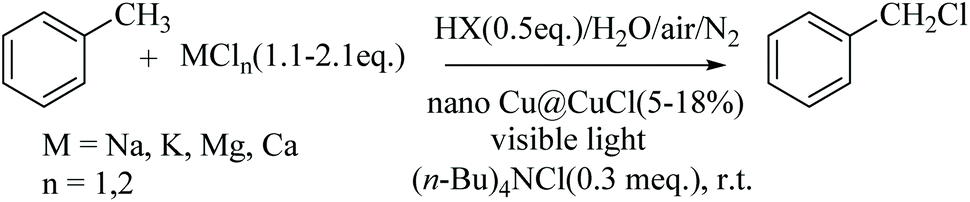
The chlorination of C–H bonds is one of the most important and basic chemical processes for the synthesis of organic starting materials and fine chemicals.1 In the traditional chlorination of aliphatic C–Hs which uses Cl2, the maximum utilisation of chlorine is only 50% since half of the dichlorine forms HCl as a by-product, which often has to be transformed to NaCl in most chlorination industrial processes for subsequent disposal as industrial solid waste salt; a non-trivial treatment problem. However, the re-utilisation of this chloride source, rather than being treated as waste, would be highly desirable but is also an exceedingly difficult challenge. Despite the fact that NaCl is a major feedstock for producing Cl2 in the chlor-alkali industry, it requires high energy consumption for its generation. In addition, the selectivity of the direct dichlorine-based chlorination of C(sp3)–Hs is not attractive because of the high concentration of chlorine free radicals required in the reaction system, often affording poly-chlorinated by-products. Hence, the current industry-standard chlorination approach does not conform to a strategy of either atomic economy or the principles of green chemistry and sustainable chemical development. Although new methods of benzylic C–H chlorination have been reported recently involving amide N–Cl compounds as chlorinating agents, or alternatively, Zhdankin's azidoiodinane (Fig. 1, reagent A) and Cu(II) complex,2 there is still a need for new strategies which control the production of the Cl2, and preferably involving coupling its generation to an in situ process using inorganic chloride in aqueous solution as a green, cleaner and sustainable chlorine source. In spite of the fact that the chlorination of C–Hs with inorganic chlorides does not occur readily, some preliminary research using inorganic chlorides as chlorination agent have been reported. For example, in the presence of strong oxidants, such as Na2S2O8, Ce(NH4)2(NO3)6, oxone, or under visible light with noble-metal co-catalysis, NaCl, LiCl and CuCl2 can all be used as chlorine sources to carry out the chlorination of C–Hs, which can even successfully chlorinate tertiary C–H positions.3 However, the strong oxidants used in these procedure have also resulted in new waste issues that again do not conform to green chemical principles. | ||
| Fig. 1 C–H chlorination with chloride ion. | ||
As part of our ongoing research to develop a low-cost, green and sustainable method of C–H chlorination using a green chlorine sources typified by MCln in water with dioxygen from air as the oxidant (as opposed to strong chemical oxidising agents) and preferably at room temperature, we wanted to develop a novel, green, in situ chlorine-generating system using suitable co-catalysts and visible light, avoiding the use of noble metals, i.e. Pd, Ru and Ag, as detailed in Fig. 1,3 and looked instead at Cu in particular as a cheap, sustainable metal catalyst-based system.
Visible light photocatalysis has recently become a versatile activation method for chemical reactions,4 with composites of semiconductors and noble metal nanoparticles such as Ag, Au, Pt and Pd commonly being used as the photocatalysts because the noble metal exhibits characteristic optical absorption bands at visible wavelengths.5 To achieve atom economic goals, the earth-abundant transition metal, copper would be an ideal alternative to the more expensive noble metals due to copper's wide-range of accessible oxidation states from 0 to III, and hence, the use of nano-Cu/semiconductors as possible visible light-active photocatalysts has become a new area of research focus.6 In particular, visible light photocatalysts based on copper, such as Cu2O and nano-Cu composites Cu@TiO2, Cu–Pd, Cu/SiO2, Cu/ZnO and Cu/RGO have emerged as novel activation tools.7,8 However, nano-Cu@CuCl, a metal–semiconductor composite and potential visible light photocatalyst has not yet been reported, and herein, we report its formation and use in photocatalytic chlorination reactions.
Results and discussion
In order to achieve a new, atom economic, green and sustainable selective chlorination of C–Hs with MCln as chlorinating agent under visible light photocatalytic conditions, the catalyst, nano-Cu@CuCl was firstly synthesised and found to exhibit significant high activity and selectivity for the chlorination of C(sp3)–H moieties especially with MCln/AcOH mixtures and without the need for strong oxidising agents at room temperature. It was also found that the chloride source, MCln, could be one of NaCl, KCl, MgCl2 or CaCl2, or a mixture of multiple chlorides such as bittern (a salt mixture obtained from seawater). The result is a novel green chlorination system of C(sp3)–H bonds which occurs readily in water using simple inorganic chlorides MCln as the chlorine source, dioxygen (from air) as the oxidant, a low-cost co-catalyst nano-Cu@CuCl and visible light at room temperature. In addition, it was also possible to develop an efficient serial reactor system in order to apply the visible light-mediated photocatalytic chlorination technology. Mechanism studies have also showed, through electron spin resonance (ESR) on the DMPO-Cl radical, that the reaction belongs to a free radical process.Synthesis and characterization of nano-Cu/CuCl
Both nano-Cu and nano-CuCl can be prepared via the reduction of a Cu(II) salt with various reducing agents. Although a hydrothermal approach offers advantages for the reduction of Cu(II) to Cu(I) in situ (especially for the preparation of Cu(I) halide aggregates), metallic Cu nanoparticles are made via “wet chemistry”.9 Hence, a nano-Cu@CuCl composite was first prepared by the hydrothermal method in a one-step, controlled, selective reduction of a Cu(II) salt, using either copper(II) sulfate or chloride, KCl and the reducing agent, reacted in a Teflon-lined stainless steel autoclave. The autoclave was held at 130–165 °C and the reaction occurred over 12–24 h under N2. The resulting brown precipitate was filtered and washed with distilled water and ethanol to produce the nano-Cu@CuCl.This reduction of Cu(II) to nano-CuCl and nano-Cu was selective when carried out using this in situ approach and the ratio of nano-Cu to nano-CuCl was found to be strongly dependent upon the hydrothermal reaction conditions, including the type and amount of reducing agent, the type of Cu(II) salt, the reaction temperature and the reaction time. The results of these reactions under different conditions are shown in Table 1.
| No. | Cu(II) salt | Reducing agent | T (°C) | Time (h) | Loading level (%) |
|---|---|---|---|---|---|
| 1 | CuSO4 | Vitamin C | 130 | 12 | 1.6 |
| 2 | CuSO4 | Vitamin C | 140 | 12 | 3.4 |
| 3 | CuSO4 | Vitamin C | 150 | 12 | 5.2 |
| 4 | CuSO4 | Glucose | 130 | 12 | 6.5 |
| 5 | CuCl2 | Vitamin C | 150 | 12 | 7.5 |
| 6 | CuCl2 | Glucose | 140 | 24 | 9.6 |
| 7 | CuCl2 | Glucose | 150 | 12 | 11.3 |
| 8 | CuCl2 | Glucose | 150 | 24 | 12.7 |
| 9 | CuSO4 | Glucose | 150 | 24 | 16.9 |
| 10 | CuSO4 | HCO2Na | 150 | 24 | 8.5 |
| 11 | CuSO4 | HCO2NH4 | 150 | 24 | 8.5 |
| 12 | CuCl2 | Formalin | 150 | 24 | 9.4 |
| 13 | CuSO4 | PhCHO | 150 | 24 | 10.2 |
| 14 | CuSO4 | HCO2H | 150 | 24 | 10.1 |
Table 1 also shows the impact of the anions of the Cu(II) salt on the loading level of nano-Cu in the composite. Compared with chloride, sulfate ions were found to be more favourable for yielding the composite with suitable nano-Cu(0) loading levels. Therefore, chalcanthite was selected as the Cu source for the preferred preparation of the nano-Cu@CuCl. In addition, the selection of reducing agent was critical in the preparation process. Organic reducing agents, including formic acid and its related derivative, formalin, and benzaldehyde, glucose and vitamin C were studied. The results clearly showed that glucose was the best reducing agent under neutral conditions. It was also found that the nano-Cu loading level in the composite depended strongly on the reducing agent dosage used. When the ratio of the Cu(II) salt to reducing agent was greater than 1![[thin space (1/6-em)]](https://www.rsc.org/images/entities/char_2009.gif) :12 (mol), Cu@CuCl with a loading level of 10 mol% nano-Cu was obtained (Table 1, entries 7, 8, 9, 13 and 14). The optimal ratio of CuSO4 to glucose was between 1:12 and 1:16. Finally, the loading level of nano-Cu increased with increasing temperature and the products obtained at 145–150 °C exhibited clear and orderly morphological characteristics (Table 1). It was difficult to obtain nano-Cu(0) below 120 °C under neutral reducing conditions, however, at temperatures above 150 °C, the morphological characteristics of the composite were disordered and the size of the Cu particles was on the micron scale. Indeed, the composition, structure and optical properties of the resulting Cu@CuCl were investigated by XRD, TEM, HRTEM SEM and XPS. Fig. 2a shows the X-ray diffraction pattern of Cu@CuCl composites with different loading levels of nano-Cu. In the Cu@CuCl products, the nano-Cu was in the cubic phase (JCPDS card no.: 04-0836) and the CuCl was also in the cubic phase (JCPDScard no.: 06-0344). The UV-visible absorption spectra of nano-Cu@CuCl with nano-Cu of different loading levels and CuCl are shown in Fig. 2b. Surface plasmon resonance between nano-Cu and nano-CuCl leads to a strong absorption of the composite in the visible region (380–800 nm) and the absorption become stronger with the increasing of nano-Cu loading level.
:12 (mol), Cu@CuCl with a loading level of 10 mol% nano-Cu was obtained (Table 1, entries 7, 8, 9, 13 and 14). The optimal ratio of CuSO4 to glucose was between 1:12 and 1:16. Finally, the loading level of nano-Cu increased with increasing temperature and the products obtained at 145–150 °C exhibited clear and orderly morphological characteristics (Table 1). It was difficult to obtain nano-Cu(0) below 120 °C under neutral reducing conditions, however, at temperatures above 150 °C, the morphological characteristics of the composite were disordered and the size of the Cu particles was on the micron scale. Indeed, the composition, structure and optical properties of the resulting Cu@CuCl were investigated by XRD, TEM, HRTEM SEM and XPS. Fig. 2a shows the X-ray diffraction pattern of Cu@CuCl composites with different loading levels of nano-Cu. In the Cu@CuCl products, the nano-Cu was in the cubic phase (JCPDS card no.: 04-0836) and the CuCl was also in the cubic phase (JCPDScard no.: 06-0344). The UV-visible absorption spectra of nano-Cu@CuCl with nano-Cu of different loading levels and CuCl are shown in Fig. 2b. Surface plasmon resonance between nano-Cu and nano-CuCl leads to a strong absorption of the composite in the visible region (380–800 nm) and the absorption become stronger with the increasing of nano-Cu loading level.
 | ||
| Fig. 2 (a) X-ray diffraction data of Cu/CuCl, Cu and CuCl; (b) UV-visible absorption spectra of Cu/CuCl and CuCl. | ||
The scanning and transmission electron microscopy results from Cu@CuCl are shown in Fig. 3a and b. Notably, nano-Cu(0) was deposited on the surface of the CuCl particles to form a Cu-CuCl composite; the diameter of the nano-Cu(0) was approximately 5 nm and the diameter of the CuCl was approximately 100–200 nm. The HRTEM photograph of Cu@CuCl in Fig. 3c shows that the interplanar spacing of Cu (111) is 0.28 nm and that the interplanar spacing of CuCl (111) was 0.37 nm. The elemental composition and chemical status of the samples were also examined by X-ray photoelectron spectroscopy (XPS). XPS spectra of Cu 2p, Cu LMM and Cl 1s in Cu@CuCl are given in Fig. 4. The Cu 2p spectra of Cu@CuCl consisted of two individual peaks at approximately 932.0 eV and 951.9 eV, which can be attributed to Cu 2p3/2 and Cu 2p1/2, with a peak separation of 20 eV, indicating that the valence states of the Cu ion were +1 and 0 (Fig. 4a). The Cu LMM XPS results showed that two Cu species (Cu+ and Cu0) existed in the composite. The Cu LMM peak at approximately 915.6 eV can be attributed to Cu+, and the Cu LMM peak at approximately 918.0 eV can be attributed to Cu(0) (Fig. 4b). Fig. 4c shows the Cl 2p region of the X-ray photoelectron spectra. The Cl 2p peak shows two components at 198.4 eV and 200.0 eV, which can be assigned to Cl 2p3/2 and Cl 2p1/2 of Cu@CuCl, respectively.
 | ||
| Fig. 3 (a) SEM image of Cu/CuCl; (b) TEM image of Cu/CuCl; (c) HRTEM image of Cu/CuCl. | ||
 | ||
| Fig. 4 (a) Cu 2p XPS of Cu/CuCl; (b) Cu LMM XPS of Cu/CuCl; (c) Cl 2p of Cu/CuCl. | ||
Photocatalytic chlorination of C(sp3)–H moieties with MCln solution
This novel Cu-based catalyst was then applied to the chlorination of different alkylarene α-Hs and cyclic hydrocarbons as well as the chlorination of ketone α-Hs, all using an inorganic chloride MCln aqueous solution under visible light. These reactions worked smoothly and could also be adapted in a three reactor serial arrangement approach, exemplified by the chlorination of toluene and cyclohexane which gave 90 and 83% yields, respectively. In addition, the chlorination of ketone α-H substitution was found to be not only highly selective but also gave high conversions. For example, the monochlorination of cyclohexanone afforded 96% selectivity. It was important that this chlorination of aliphatic C–Hs approach not only provided a direct and green transformation of inorganic chlorides to organic chlorides in H2O, but is also an excellent strategy for the re-use of industrial inorganic chlorides.Next, we compared the noble metal catalyst analogue, nano-Ag@AgCl, for its visible light photocatalytic activity for the chlorination of C–Hs with KCl solution under hydrochloric acid conditions to the catalytic activity of the nano-Cu@CuCl version of the photocatalyst. Under either strongly or weakly acidic condition, the composite exhibited high catalytic activity for C(sp3)–H chlorination with chloride ion without any stronger oxidant, just using visible light.
The mixture of toluene, KCl/HCl solution, and tetrabutylammonium chloride (TBAC) was treated for 5–6 h with stirring at room temperature under the co-catalysis of nano-Cu@CuCl and visible light, which was produced by irradiation with a 300 W Xe arc or LED lamp. The GC results for the reaction showed that benzylchloride was the only product (Table 2, entry 1). As expected, the nano-Cu/CuCl had excellent photocatalytic activity for the chlorination of toluene with KCl/HCl solution in the presence of air, however, in the absence of either the Cu/CuCl photocatalyst or visible light, the chlorination did not take place at all. In addition, when the Cu/CuCl catalyst was used five times in succession, the conversion of toluene was 44–48%, and the catalyst activity and weight remained basically as shown in Fig. 5a.
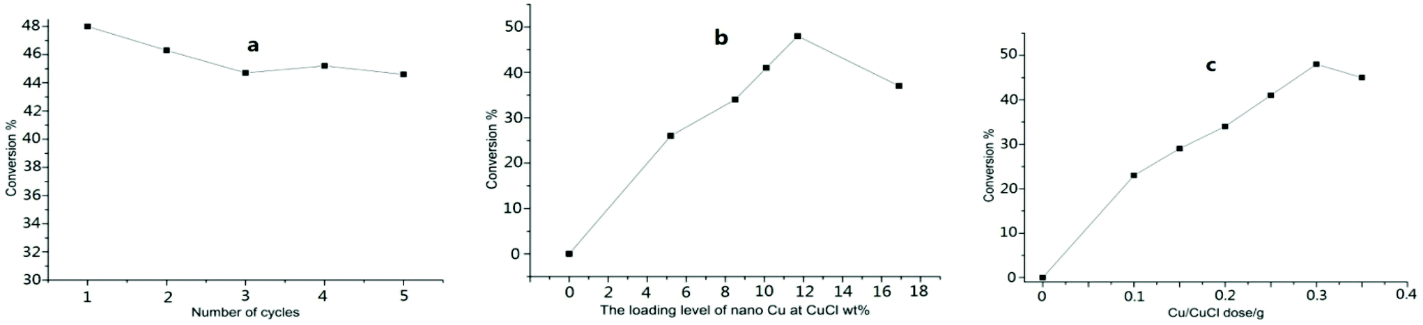 | ||
| Fig. 5 (a) The conversion of toluene vs. number of cycles; (b) effect of nano-Cu loading level on the conversation of toluene (from 0 to 16.9 mol%. 0.3 g); (c) effect of Cu/CuCl (nano-Cu loading level 11 mol%) dose on the conversation of the toluene (from 0 to 0.35 g, conversion from 0 to 48%). | ||
|
|
|||||||
|---|---|---|---|---|---|---|---|
| No. | X | Cl source | N2/Air | T (h) | Selec. (%) | Conva (%) | Yieldd (%) |
| a Conversion for a single catalyst addition on a single reaction. b Conversion for multiple, portion-wise catalyst additions to a single reaction. c Conversion for the tandem chlorination result. d Isolated yield. | |||||||
| 1 | Cl | KCl | Air | 5 | 98 | 28 | 26 |
| 2 | AcO | KCl | Air | 5 | 94 | 38 | 33 |
| 3 | AcO | KCl | 10% | 6 | 95 | 50 | 46 |
| 4 | AcO | NaCl | 10% | 5 | 96 | 49 | 45 |
| 5 | AcO | NaCl | 10% | 8 | 94 | 50 | 46 |
| 6 | AcO | MgCl2 | 10% | 5 | 95 | 53 | 49 |
| 7 | AcO | CaCl2 | 10% | 5 | 95 | 51 | 47 |
| 8 | AcO | MCln | 10% | 6 | 97 | 55 | 51 |
| 9 | AcO | bittern | 10% | 6 | 98 | 56 | 53 |
| 10 | AcO | bittern | 10% | 6 | 98 | 71b | 68 |
| 11 | AcO | bittern | 10% | 6.5 | 98 | 92c | 89 |
| 12 | AcO | bittern | 10% | 6.5 | 98.5 | 92c | 90 |
To establish a more effective approach for toluene chlorination, many conditions influencing the reaction, such as catalyst, chloride source, ratio of N2 to air and types of acids were studied and optimised further. Fig. 5b and c show the relationships between the conversion and the catalyst dosage and the nano-Cu loading level in the Cu/CuCl catalyst itself. Although the higher loading levels within 0–12 mol% range were favourable for the conversion, better results were generally obtained using the catalyst at a loading level higher than 10 mol%. While with Cu loading levels higher than 12 mol% in the composites, did not provide any apparent improvement in the contribution. In addition, the conversion of toluene increased with an increased dose level of the photocatalyst with nano-Cu loading at level 11 mol%, however, the conversion did not increase as the photocatalyst amount rose above 0.3 g for treating 0.4 mol of substate.
The effect of the chloride source MCln as chlorinating agent on the reaction was also studied. The results show that the cation M in MCln was not significant for either the conversion, selectivity or yield of toluene chlorination (Table 2, entries 3, 4, 5, 6 and 7), but the common-ion effect in a mixture of multi-chlorides, such as bittern and  (mixture of CaCl2-KCl or NaCl) did favourably affect the reaction (Table 2, entries 8 and 9). Hence, bittern acts as an effective chloride source to execute the reaction with higher conversion and selectivity.
The data in Table 2 also shows that the ratio of air to nitrogen was a key factor for efficiently executing the reaction. Air was used as the oxidising agent to transfer the photogenerated electrons to allow the reaction to occur. However, under oxygen-enriched conditions, CuCl is easily oxidised, resulting in a loss of the catalytic activity. Therefore, in air diluted with N2 (N2/air = 10%), the chlorination of toluene gave a higher conversion (Table 2, entries 2 and 3). An acidic medium was also an essential variable for the reaction. Although a strongly acidic medium, such as HCl, can be used for the reaction, its corrosiveness had a markedly destructive effect upon the photocatalyst over both long-term and multiple use conditions. To determine the optimal conditions, different acids were tested for the process and the results (Table 2, entries 1 and 2) showed that using nano-Cu@CuCl as the photocatalyst, in the presence of acetic acid was better than using HCl.
Under similar conditions, the chlorination of some substituted toluenes, such as ethylbenzene, 4-t-Bu-toluene, 4-Cl-toluene and 4-F-toluene was carried out using the optimised reaction conditions, giving highly satisfactory results in terms both the selectivity and conversion, as shown in Fig. 6.
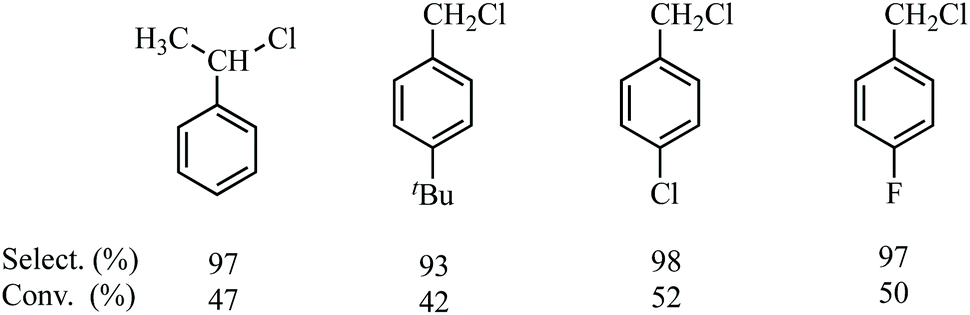 | ||
| Fig. 6 Selection, yield and conversion of the chlorination of some substituted toluenes. | ||
Analysis of the toluene chlorination results showed that in most case the conversion was about 50%. However, it was also found that if the nano-Cu@CuCl photocatalyst was added in batches, it had a favourable effect on the reaction conversion (Table 2, entry 10). Also, the same experimental result was obtained for the toluene chlorination system with NaCl solution under co-catalysis of Ag/AgCl and visible light.2b These results show that it is important to enhance mass transfer on the surface of catalyst, especially in this type of complex multi-phase reaction. Strengthening the contact probability between the surface active sites of the solid catalyst and the substrate, accelerating the transfer of photogenerated electrons and efficiently utilising the visible light are effective strategies for improving the reaction conversion. Hence, a chlorination approach was designed and developed using three photocatalytic reactors in series. In this system, the reactors A, B, and C were placed in order from high (top) to low (bottom) positions relative to each other (see ESI†). A mixture of MCln/HOAc solution, tetrabutylammonium chloride (TBAC) and nano-Cu@CuCl was added to the reactors, followed by toluene, to reactor A (top) and stirred for 2 h at room temperature under visible light irradiation conditions. The organic phase was then transferred to reactor B (middle) and treated under the same conditions for a further 2 h. Again, the organic phase was transferred to reactor C (bottom) to repeat the same process for a third time. After the reaction was completed, GC of the final recovered organic mixture showed that the conversion of toluene was over 92% and after fractionation, gave 90% of the chlorination product benzylchloride and 7% toluene. However, it should be pointed out that total amount of nano-Cu@CuCl in the system was almost the same as with the previous method, just that it was divided into three portions to add to the respective reactors, adding up to a total catalyst loading of 0.18–0.2 g (about 10 mol% loading level of nano-Cu) and with the same level of dosage in each photoreactor. Also, the inorganic mixture left in each reactor could be reused for subsequent toluene chlorinations. Thus, a new toluene chlorination approach was established using bittern as a chloride source and the serial chlorination working well in the acidic medium using acetic acid under a mixture of air and air and N2. Under these conditions, the total conversion of toluene increased to 92% and the reaction yield to over 90%, with a selectivity higher than 98%. The results shown in Table 2 (entries 11 and 12).
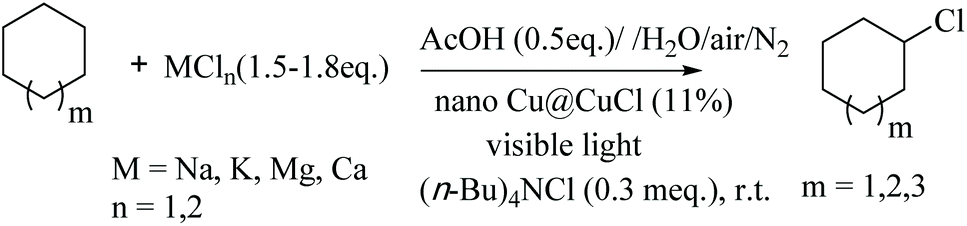
Taking these results further, the chlorination of C–H bonds in saturated alicyclic hydrocarbons was also performed in a bittern/AcOH solution using the nano-Cu/CuCl and visible light co-catalysis, at room temperature under the optimised conditions. The chlorination occurred readily with conversions of cyclohexane and cyclooctane of 55% and 42%, respectively, under solvent-free conditions. The selectivity of the reactions were higher than 90% and the monochlorination products were cleanly afforded, as shown in Table 3 (entries 1, 2 and 3). For comparison, when cyclohexane was chlorinated with bittern by applying the serial-reactor technology, the conversion of cyclohexane increased to about 90%, and the selectivity and yield were higher than 95% and 83%, respectively, as shown in Table 3 (entries 4 and 5).
The most obvious advantage of this method is that the chlorination of C–H bonds is achieved through the in situ production of dichlorine catalysed by cheap and recyclable nano Cu/CuCl and visible light. The chloride ion itself is consumed rather than using chlorine gas, hence, there is no problem of hydrogen chloride by-product formation, which means a substantial improvement in greenness and sustainability.
Mechanism and further examples
The C–H chlorination using the nano-Cu/CuCl system with visible light co-catalysis is a multi-phase reaction system, with complex mass- and electron-transfers involved in the reaction.A reasonable mechanism for such a chlorination reaction involves a free radical process, whereby nano-Cu is irradiated with visible light, a photon is absorbed producing an excited state [Cu/CuCl]*, an excited electron (known as a photogenerated electron) and an empty orbital (hole) is generated. The hole accepts an electron from the CuCl, resulting in in situ oxidation on the catalyst surface to form Cu2+, and a photogenerated electron is transferred to O2 dissolved in the acidic water, to firstly yield a hydrogen peroxide free radical. This then oxidises chloride ion in the reaction solution to form chlorine radical which triggers the free radical reaction. On the other hand, the hydrogen peroxide produced could further oxidise chloride ion to dichlorine, driving the C–H chlorination directly. Under insufficient oxygen conditions, Cu2+ could be reduced by the photogenerated electron and combined with chloride ion to recover CuCl from the photocatalyst composite. The proposed mechanism is shown in Scheme 1.
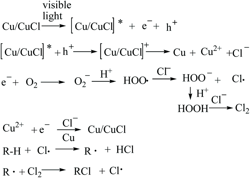 | ||
| Scheme 1 Proposed chlorination reaction mechanism. | ||
In this process (Scheme 1), both the chlorine radical and the dichlorine produced in situ are key, reactive species. In order to determine if dichlorine was indeed being formed, a new chlorination experiment in which the substrate, toluene, was replaced by cyclohexene, together with a few ketones, in order to examine their resulting product profiles, and hence, indicate the likely mechanism operating.
When cyclohexene was treated with NaCl/AcOH without any strong oxidation reagent under the co-catalysis of nano-Cu/CuCl and visible light conditions, the GC of the reaction mixture showed that the main products were 1,2-di-Cl-cyclohexane and 2-Cl-cyclohexanol (Scheme 2). These products are characteristic of an addition reaction to the C![[double bond, length as m-dash]](https://www.rsc.org/images/entities/char_e001.gif) C by dichlorine in water, a result which clearly reveals that dichlorine was produced in the photocatalytic reaction system.
C by dichlorine in water, a result which clearly reveals that dichlorine was produced in the photocatalytic reaction system.
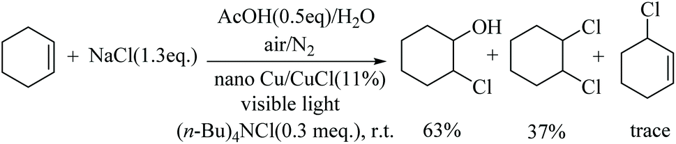 | ||
| Scheme 2 The chlorination of cyclohexene. | ||
Furthermore, when acetophenone was treated with the bittern/AcOH solution under the nano-Cu/CuCl and visible light co-catalysis, room temperature, conditions, α-Cl-acetophenone was afforded in 49% conversion and 94% selectivity (Scheme 3). The chlorination of different ketones with α-Hs also took place in a similar manner, including 4-Cl-acetophenone, pinacolone and cyclohexanone. Hence, chlorination of these substrates gave α-H monochlorination products with high selectivity, and indeed, higher than those obtained from the traditional reaction of cyclohexanone with Cl2 (the chlorination of cyclohexanone being especially noteworthy) (see Scheme 3). The chlorination of ketone α-Hs does require dichlorine, or its aqueous solution, in order for the reaction to take place under polar reaction conditions, i.e. via the enol of ketone, rather than via free radical reactions, as with the hydrocarbons. These results confirmed again that dichlorine was therefore produced in situ during the chlorination of C–Hs. Although the dichlorine was not detected in the gas phase, the fact that a low concentration of dichlorine is produced is clearly indicated, which inhibits the rate of free radical formation and results in a high selectivity of C–H chlorination.
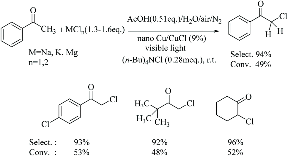 | ||
| Scheme 3 Chlorination of some methyl ketones and cyclohexanone. | ||
The fact that chlorine free radicals were generated under the reaction conditions was also confirmed by electron spin resonance (ESR) (Fig. 7). Hence, 5,5-dimethyl-1-pyrroline-N-oxide (DMPO) was employed as a scavenger to trap chlorine radicals, which was then oxidised from DMPO to form DMPO-Cl. under visible light irradiation and the catalysis of nano-Cu/CuCl. Typical DMPO-HO. signals were not detected under either DMPO + NaCl with visible light or Cu/CuCl in the dark, while a standard nine-line ESR spectrum of DMPO-Cl˙ was identified as the oxidised derivative of DMPO via Cl˙ oxidation,10 which appeared in the mixture of DMPO and Cu/CuCl when exposed to visible light, intuitively showing the generation of chlorine radical by the visible light photocatalysis of nano-Cu/CuCl.
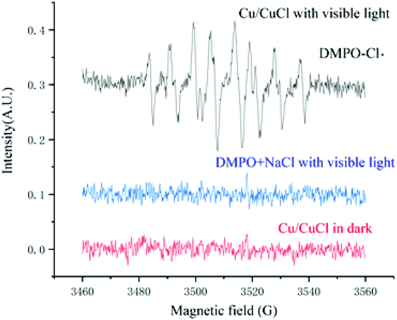 | ||
| Fig. 7 ESR spectra of DMPO capturing generated chlorine radical. | ||
The XRD results of the catalyst after five reactions (see the ESI†) showed that the nano-copper content increased significantly. This result indicates that both CuCl2 and CuCl were partially reduced by the photogenerated electrons to give nano-copper in concert. Also, the visible light decomposition of CuCl could be one of the main reasons for the Cu(0) content increasing in the catalyst composition.11 At the same time, during chlorination, the reaction solution changed from colourless to light blue, and the XRD of the photocatalyst separated from the catalytic reaction system showed that there was about 1% Cu(II), indicating that the transformation of Cu(I) to Cu(II) had occurred.
Conclusions
In conclusion, the low-cost visible light photocatalyst nano-Cu/CuCl was synthesised via reduction of a copper salt with glucose and KCl solution in a one-step hydrothermal reaction. The nano-Cu/CuCl was characterised by XRD, TEM, HRTEM and XPS, and its catalytic activity evaluated by investigating the chlorination of different C–H bonds. The results showed that the nano-Cu/CuCl system is a new and efficient, room temperature-active, photocatalyst for the direct and selective chlorination of C(sp3)–Hs when used together with an MCln solution, and avoids the use of either a strong oxidation reagent or electrolysis. This green chemical technology was further extended by utilisation in a serial, triple, visible light photocatalytic reactor system and exemplified through the chlorination of toluene and cyclohexane which afforded conversions of 92% and 90%, respectively. The mechanism of the visible light photocatalytic chlorination was also studied and involves the formation of chlorine free-radicals, as verified by ESR. This approach has broad applicability and good prospects for use in the chemical industry to address the chlorine balance, and for the development of more sustainable and energy efficient reactions.Experimental
General experimental
All chemicals were of analytical grade and purchased from Aladdin Reagent Co., Ltd and Sinopharm Chemical Reagent Co. Ltd and were used without further purification unless noted otherwise. Bittern (8% NaCl, 3% KCl, 10% MgCl2) was obtained from Tangshan Haigang Xuning Chemical Co., Ltd. The morphology of the Cu/CuCl composite was characterized using a high-resolution transmission electron microscopy (HRTEM, JEOL JEM-2010) equipped with an electron diffraction (ED) attachment with an acceleration voltage of 200 kV and a scanning electron microscope (SEM; Hitachi S4800 SEM) with an accelerating voltage of 30.0 kV. The crystal was determined by X-ray diffraction (XRD) using a diffractometer with Cu-Kα radiation (Shimadzu Lab-X XRD-6000). The accelerating voltage and applied current were 40 kV and 30 mA, respectively. The light absorption properties were measured using a UV–vis diffuse reflectance spectrophotometer (DRS, JASCO, UV-550) with a wavelength range of 200–900 nm. X-ray photoelectron spectroscopy (XPS) measurements were performed using a Thermo Fisher Scientific K-Alpha spectrometer (ESCALAB 250Xi). Data analysis was performed using XPSPEAK41 software. The binding energy was corrected for surface charges by taking the C 1s peak of contaminant carbon at 284.8 eV as a reference. A 300 W xenon lamp (λ > 290 nm, PLS-SXE300CUV, Perfectlight Instruments Co. Ltd, Beijing) was used as the light source, and the average light intensity was 78.5 mW cm−2 (UV-A radiation meter). LED lamp has a main wavelength of 465 nm, a wavelength range of 460–470 nm, and a light power of 20 W. GC data were recorded on a SHIMADZU 2014C. GC-MS data were measured with a Thermo Scientific ISQ QD. 1H NMR were recorded on a Bruker Avance II 500 spectrometer in CDCl3 unless stated otherwise, using tetramethylsilane as an internal reference, operated at 500.13 MHz, and J values are given in Hz. Electron spin resonance (ESR) spectra were measured using a Bruker Electron Paramagnetic Resonance Spectrometer (ESP 500E).Preparation of nano Cu/CuCl
A total of 160 mg (0.64 mmol) of CuSO4·5H2O powder, 74.6 mg (1 mmol) potassium chloride, 0.92–1.84 g (5.12–10.24 mmol) of D-(+)-glucose powder and 40 mL deionized water were added to a 50 mL Teflon-lined stainless steel autoclave and stirred to dissolve. The autoclave was sealed and heated at 130–165 °C for 12 h or 18 h or 24 h and then allowed to cool to room temperature naturally. The obtained product was collected by filtration and washed with deionized water and alcohol. Then, the sample was dried at ambient temperature under vacuum for 12 h. Nano-Cu/CuCl with a loading level of 1.6–17.5% was obtained.Photocatalysed chlorination of C(sp3)–H moieties under visible light
The phase transfer catalyst TBAC (0.420 g, 1.5 mmol) was added to a photocatalytic reaction vessel (PLS-SXE300CUV) charged with 0.5 mol of substrate. After stirring, 150 mL of 22% MCln solution and 12 mL (0.21 mol) of acetic acid were added to the above solution, and then N2 was inlet. Under magnetic stirring, a 300 W xenon lamp was used as the light source to irradiate the reaction mixture. Cu/CuCl (0.46 g) containing 5–18 mol% nano-Cu was added in 3 batches to the reaction vessel at intervals of 1–2 h as the reaction proceeded. The reaction was monitored by GC. The reaction solution was filtered to reclaim the photocatalyst, and the solution was separated after the reaction ended. The inorganic phase was collected for the next use, and the organic phase was dried over anhydrous MgSO4 and filtered to collect the solution. The chloride product was obtained by fractionation, and unreacted starting material was collected to use in the next reaction.The photocatalytic chlorination of cyclohexene
The phase transfer catalyst TBAC (0.50 g, 1.8 mmol) was added to a photocatalytic reaction vessel (PLS-SXE300CUV) charged with 0.6 mol of substrate. After stirring, 150 mL of bittern and 20 mL (0.35 mol) of acetic acid were added to the above solution. Under magnetic stirring, a xenon lamp was used as the light source to irradiate the reaction mixture. Cu/CuCl (0.8 g) containing 11 mol% nano-Cu was added to the reaction vessel. The reaction was monitored by GC. The reaction solution was filtered, separated. The organic phase was dried over anhydrous MgSO4 and filtered to collect the solution. The chlorination product was obtained by evaporation to give a mixture of 2-chlorocyclohexanol and 1,2-dichlorocyclohexane. GC-MS showed that both products were obtained in 16.5% and 9.8%, respectively, with the ratio being approximately 63:37. 2-Chlorocyclohexanol (CAS registry no: 1121-21-7), GC-MS (m/z) 134. [M]+ (cald for C6H11ClO, 134.05). 1,2-Dichlorocyclohexane (CAS registry no: 1561-86-0), GC-MS (m/z) 152.0 [M]+ (cald for C6H10Cl2, 152.02).
The photocatalytic chlorination of ketones
The phase transfer catalyst TBAC (0.30 g, 1.1 mmol) was added to a photocatalytic reaction vessel (PLS-SXE300CUV) charged with 0.4 mol of substrate. After stirring, 150 mL of bittern and 15 mL (0.26 mol) of acetic acid were added to the above solution, and then N2 was inlet. Under magnetic stirring, a LED lamp or xenon lamp was used as the light source to irradiate the reaction mixture. Cu/CuCl (0.5 g) containing 9 mol% nano-Cu was added in 4 batches to the reaction vessel at intervals of 2 h as the reaction proceeded. The reaction was monitored by GC. The reaction solution was filtered, separated. The organic phase was dried over anhydrous MgSO4 and filtered to collect the solution. The chloride product was obtained by rectifying and recrystallization.Conflicts of interest
There are no conflicts to declare.Acknowledgements
The authors are grateful for the financial assistance received from the Natural Science Foundation of China (grant number 21978067,), the Basic Research Program of China (grant numbers 2010CB512007 and 2012CB723501), and the Key Basic Research Project of the Hebei Province of China (grant number 12966737D). The authors are grateful to Dr Jihong Liu (Technical Institute of Physics and Chemistry, CAS) for ESR, UV-visible absorption spectra, and XPX experiments and Dr Bo Li (Hebei University of Science & Technology) for XRD, SEM, TEM and HRTEM experiments.References
- R. Lin, A. P. Amrute and J. Pérez-Ramírez, Chem. Rev., 2017, 117, 4182–4247 CrossRef CAS.
- (a) X.-L. Lv, K. Wang, B. Wang, J. Su, X. Zou, Y. Xie, J.-R. Li and H.-C. Zhou, J. Am. Chem. Soc., 2017, 139, 211–217 CrossRef CAS PubMed; (b) S. Liu, Q. Zhang, X. Tian, S. Fan, J. Huang and A. Whiting, Green Chem., 2018, 20, 4729–4737 RSC; (c) M. Zhao and W. Lu, Org. Lett., 2017, 19, 4560–4563 CrossRef CAS PubMed; (d) K. J. Stowers, A. Kubota and M. S. Sanford, Chem. Sci., 2012, 3, 3192–3195 RSC; (e) R. K. Rit, M. R. Yadav, K. Ghosh, M. Shankar and A. K. Sahoo, Org. Lett., 2014, 16, 5258–5261 CrossRef CAS; (f) R. Giri, X. Chen and J. Yu, Angew. Chem., Int. Ed., 2005, 44, 2112–2115 CrossRef CAS; (g) A. Fawcett, J. Keller, Z. Herrera and J. F. Hartwig, Angew. Chem., Int. Ed., 2021, 60, 8276–8283 CrossRef CAS.
- (a) W. Dong, Y. Liu, B. Hu, K. Ren, Y. Li, X. Xie, Y. Jiang and Z. Zhang, Chem. Commun., 2015, 5, 4587–4590 RSC; (b) K. Zeitler, Angew. Chem., Int. Ed., 2009, 48, 9785–9789 CrossRef CAS; (c) T. P. Yoon, M. A. Ischay and J. Du, Nat. Chem., 2010, 2, 527–532 CrossRef CAS; (d) J. W. Tucker and C. R. J. Stephenson, J. Org. Chem., 2012, 77, 1617–1622 CrossRef CAS; (e) J. Xuan and W.-J. Xiao, Angew. Chem., Int. Ed., 2012, 51, 6828–6838 CrossRef CAS PubMed; (f) D. M. Schultz and T. P. Yoon, Science, 2014, 343, 1239176 CrossRef PubMed; (g) M. N. Hopkinson, B. Sahoo, J.-L. Li and F. Glorius, Chem. – Eur. J., 2014, 20, 3874–3886 CrossRef CAS PubMed.
- (a) D. Ravelli, M. Fagnoni and A. Albini, Chem. Soc. Rev., 2013, 42, 97–113 RSC; (b) X. Yang, Y. Sun, T.-Y. Sun and Y. Rao, Chem. Commun., 2016, 52, 6423–6426 RSC; (c) Y. Wang, G.-X. Li, G. Yang, G. He and G. Chen, Chem. Sci., 2016, 7, 2679–2683 RSC; (d) K. Ohkubo, K. Mizushima, R. Iwata and S. Fukuzumi, Chem. Sci., 2011, 2, 715–722 RSC; (e) S. Liu, Q. Zhang, H. Li, Y. Yang, X. Tian and A. Whiting, Chem. – Eur. J., 2015, 21, 9671–9675 CrossRef CAS PubMed; (f) K. Sharma, M. Kumar and V. Bhalla, Chem. Commun., 2015, 51, 12529–12532 RSC; (g) A. Sagadevan, A. Ragupathi and K. C. Hwang, Angew. Chem., Int. Ed., 2015, 54, 13896–13901 CrossRef CAS.
- (a) E. Prodan, C. Radloff, N. J. Halas and P. A. Nordlander, Science, 2003, 302, 419–422 CrossRef CAS PubMed; (b) S. Gao, K. Ueno and H. Misawa, Acc. Chem. Res., 2011, 44, 251–260 CrossRef CAS PubMed; (c) C. Pacholski, A. Kornowski and H. Weller, Angew. Chem., Int. Ed., 2004, 43, 4774–4777 CrossRef CAS PubMed; (d) H. Chen, L. Shao, Q. Li and J. Wang, Chem. Soc. Rev., 2013, 42, 2679–2724 RSC; (e) A. Tanaka, K. Hashimoto, B. Ohtani and H. Kominami, Chem. Commun., 2013, 49, 3419–3421 RSC; (f) A. Kubacka, M. Fernández-García and A. Colón, Chem. Rev., 2012, 112, 1555–1614 CrossRef CAS PubMed; (g) L. Li, S. Zhang, L. Xu, J. Wang, L. Shi, Z. Chen, M. Hong and J. Luo, Chem. Sci., 2014, 5, 3808–3813 RSC; (h) Q. Deng, J. Chen, Q. Wei, Q. Zhao, L. Lu and W. Xiao, Chem. Commun., 2015, 51, 3537–3540 RSC; (i) T. Chaieb, L. Delannoy, S. Casale, C. Louis and C. Thomas, Chem. Commun., 2015, 51, 796–799 RSC; (j) K. Mori, M. Kawashima and H. Yamashita, Chem. Commun., 2014, 50, 14501–14503 RSC.
- (a) R. M. Bullock, Science, 2013, 342, 1054–1055 CrossRef CAS PubMed; (b) M. B. Gawande, A. Goswami, F.-X. Felpin, T. Asefa, X. Huang, R. Silva, X. Zou, R. Zboril and R. S. Varma, Chem. Rev., 2016, 116, 3722–3811 CrossRef CAS PubMed.
- (a) M. A. Tasdelen and Y. Yagci, Angew. Chem., Int. Ed., 2013, 52, 5930–5938 CrossRef CAS PubMed; (b) J. A. Brian, T. Youhua, J. K. Christopher, A. D. Cole, S. A. Kristi and N. B. Christopher, Nat. Chem., 2011, 3, 256–259 CrossRef; (c) M. Pirtsch, S. Paria, T. Matsuno, H. Isobe and O. Reiser, Chem. – Eur. J., 2012, 18, 7336–7340 CrossRef CAS PubMed; (d) D. B. Bagal, G. Kachkovskyi, M. Knorn, T. Rawner, B. M. Bhanage and O. Reiser, Angew. Chem., Int. Ed., 2015, 54, 6999–7002 CrossRef CAS PubMed; (e) D. T. Ziegler, J. Choi, J. M. MuÇoz-Molina, A. C. Bissember, J. C. Peters and G. C. Fu, J. Am. Chem. Soc., 2013, 135, 13107–13112 CrossRef CAS; (f) C. Uyeda, Y. Tan, G. C. Fu and J. C. Peters, J. Am. Chem. Soc., 2013, 135, 9548–9552 CrossRef CAS PubMed; (g) Y. Tan, J. M. Munoz-Molina, G. C. Fu and J. C. Peters, Chem. Sci., 2014, 5, 2831–2835 RSC; (h) A. Ragupathi, V. P. Charpe, A. Sagadevan and K. C. Hwang, Adv. Synth. Catal., 2017, 359, 1138–1143 CrossRef CAS; (i) A. Sagadevan, A. Ragupathi, C.-C. Lin, J. R. Hwu and K. C. Hwang, Green Chem., 2015, 17, 1113–1119 RSC.
- (a) J. Ran, J. Zhang, J. Yu, M. Jaroniec and S. Z. Qiao, Chem. Soc. Rev., 2014, 43, 7787–7812 RSC; (b) X. Guo, C. Hao, G. Jin;, H. Y. Zhu and X. Y. Guo, Angew. Chem., Int. Ed., 2014, 53, 1973–1977 CrossRef CAS; (c) A. Marimuthu, J. Zhang and L. S. Tuning, Science, 2013, 339, 1590–1593 CrossRef CAS PubMed.
- (a) M. B. Gawande, A. Goswami, F.-X. Felpin, T. Asefa, X. Huang, R. Silva, X. Zou, R. Zboril and R. S. Varma, Chem. Rev., 2016, 116, 3722–3811 CrossRef CAS PubMed; (b) R. Peng, M. Li and D. Li, Coord. Chem. Rev., 2010, 254, 1–18 CrossRef CAS; (c) H. Kawasaki, Y. Kosaka, Y. Myoujin, T. Narushima, T. Yonezawa and R. Arakawa, Chem. Commun., 2011, 47, 7740–7742 RSC.
- (a) T. Li, Y. Jiang, X. An, H. Liu, C. Hu and J. Qu, Water Res., 2016, 102, 421–427 CrossRef CAS; (b) R. Song, H. Wang, M. Zhang, Y. Liu, X. Meng, S. Zhai, C. Wang, T. Gong, Y. Wu, X. Jiang and W. Bu, Angew. Chem., Int. Ed., 2020, 59, 2–11 CrossRef.
- (a) X. Liu, J. Chen, P. Liu, H. Zhang, G. Li, T. An and H. Zhao, Appl. Catal., A, 2016, 521, 34–41 CrossRef CAS; (b) J. Chen, X. Liu, H. Zhang, P. Liu, G. Li, T. An and H. Zhao, Mater. Lett., 2016, 182, 47–51 CrossRef CAS.
Footnotes |
| † Electronic supplementary information (ESI) available. See DOI: 10.1039/d1gc03092b |
| ‡ These authors contributed equally. |
| This journal is © The Royal Society of Chemistry 2022 |