 Open Access Article
Research progress in stable interfacial constructions between composite polymer electrolytes and electrodes
Jun
Pan†
a,
Pei
Zhao†
a,
Nana
Wang
*b,
Fuqiang
Huang
 *ac and
Shixue
Dou
 b
b
aState Key Laboratory of High-Performance Ceramics and Superfine Microstructure, Shanghai Institute of Ceramics, Chinese Academy of Science, Shanghai 200050, P. R. China. E-mail: huangfq@mail.sic.ac.cn
bInstitute for Superconducting and Electronic Materials, University of Wollongong, Innovation Campus, Squires Way, Wollongong, New South Wales 2500, Australia. E-mail: nanaw@uow.edu.au
cState Key Laboratory of Rare Earth Materials Chemistry and Applications, College of Chemistry and Molecular Engineering, Peking University, Beijing 100871, P. R. China
First published on 10th June 2022
Abstract
Composite polymer electrolytes (CPEs) have great commercialization potential because they can take advantage of the properties of inorganic and polymer electrolytes, which enable them to realize relatively high ionic conductivity, better electrode contacts, and superior mechanical strength. Nevertheless, the interface between the CPE and the electrode material remains a key challenge that obstructs the further practical development of polymer solid-state lithium batteries (PSSBs). This is because the continuous side reactions between the electrode materials and the CPE can result in unstable interfaces during cycling, thus affecting the electrochemical performance of the battery. Here, in this review, recent advances in various interfacial constructions are reviewed, including the modification of electrode materials and optimization of CPEs. Furthermore, we specifically focus on the underlying mechanisms of the interfacial contact, ionic migration, and electrochemical reactions between the electrodes and the CPE. It is hoped that this review can stimulate greater progress towards an in-depth understanding of this interfacial issue for CPEs, which could provide specific solutions for improving the electrochemical performances of PSSBs.
Broader contextDue to the demand for high-safety and high-energy-density energy storage equipment, solid-state batteries (SSBs) have attracted worldwide attention. The solid-state electrolytes can avoid the flammability and liquid leakage issues of liquid electrolytes, which can enable the high safety of SSBs. In addition, the utilization of the lithium metal anode can further improve the energy density of SSBs. As the key component of SSBs, solid-state electrolytes have been extensively investigated. Among them, composite polymer electrolytes can take advantage of the high ionic conductivity of inorganic electrolytes and the superior flexibility of polymer electrolytes, and have great potential to achieve large-scale commercialization. However, their high interfacial resistance and unstable electrode–electrolyte interfaces inevitably lead to the deterioration of the high-energy-density and long-term stability of SSBs. So far, many strategies have been proposed to optimize the construction of composite polymer electrolytes, modify the surfaces of electrodes, and introduce a stable artificial interlayer to achieve a good interfacial contact. In this review, we have summarized the strategies to improve the cathode–electrolyte/anode–electrolyte interface stability and explore the internal mechanisms of stability improvement, and perspectives in the interface field to enhance the electrochemical performance, which will greatly promote the practical application of SSBs. |
1. Introduction
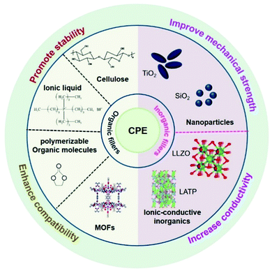
Lithium-ion batteries (LIBs) have been applied in various fields such as consumer electronics and electric vehicles in view of their light weight, freedom from the memory effect, and environmental friendliness.1–3 Due to the ever-increasing demand for high safety, durability, and energy density, as well as a suitable operation temperature range, it has become challenging for state-of-the-art LIBs to achieve goal in recent years. Solid-state batteries (SSBs), with improved safety and a wider electrochemical stability window compared with liquid ones that have flammability and liquid leakage issues, have become an exciting research direction and offer the most promising candidates for the next-generation energy storage equipment.4–11 In addition, SSBs can realize the utilization of the ‘holy grail’, the Li metal anode, which has an extremely low redox potential and the highest theoretical specific capacity, to meet the increasing demand for higher battery energy density.12,13There are two remaining bottlenecks for SSBs, however, that hinder their further commercialization. The first one is finding suitable solid-state electrolytes (SSEs) with high ionic conductivity and appropriate mechanical strength, which are the key components of SSBs. To date, with massive research efforts being devoted to designing SSEs, they can be mainly categorized into inorganic (oxides/sulfides) electrolytes (IEs), polymer electrolytes (PEs), and composite polymer electrolytes (CPEs).14–17 Among them, IEs possess the highest ionic conductivity, but their brittle character and the considerable electrode–IE interfacial resistance have hindered their practical application.18–22 PEs have the merits of superior flexibility and viscosity, but they are strictly limited by their low ionic conductivity at room temperature (10−5–10−7 S cm−1), poor mechanical strength and low thermal stability. Recently, extensive efforts have been focused on introducing fillers into the polymer matrix to form CPEs, which can take advantage of their respective properties, thereby achieving optimized mechanical properties and improving their ionic conductivity.23–29 Generally, the fillers can be classified into two categories, inorganic and organic. Inorganic fillers include nanoparticles (SiO2, TiO2 and Al2O3) and ionic-conductive inorganics (Li7La3Zr2O12 and Li2AlTi(PO4)3). They can enhance the ionic conductivity of CPEs because the inorganic fillers dispersed into the polymer matrix can reduce the crystallization of the polymer around the particle and increase the amorphous region in the electrolyte, promoting lithium ion transportation. In the case of organic fillers, polymerizable organic molecules, non-combustible ionic liquids, cellulose and metal organic frameworks (MOFs) etc. are often used to optimize CPEs. The improved interface stability is due to the bond formation between the organic fillers and the electrodes that can alter the redox stability of the electrodes, which inhibits the further side reactions of the interface (Scheme 1). Therefore, CPEs with the unique properties of high ionic conductivity and flexible characteristics can enable the future practical application of their corresponding polymer solid-state lithium batteries (PSSBs) with CPEs.
Despite the great progress in designing CPEs, their interfacial resistance and unstable electrode–CPE interfaces provide more serious constraints, leading to deterioration of the high-energy density and long-term stability of PSSBs.30–40 Their main interfacial problems include the following four aspects: (1) their high interfacial resistance across the interface is caused by the poor interfacial contact of the cathode–CPE and anode–CPE interfaces. It is challenging to construct an intimate contact between electrodes and CPEs, as there is no liquid fluidity. The poor interfacial contact of Li metal–CPE interfaces causes uneven deposition of lithium ions on the Li metal anode, increasing the risk of lithium dendrite formation. (2) The interruption of electron/ion transport caused by periodic volume changes of electrode materials and CPEs will lead to the formation of structural stress, which will accumulate continuously during the cycle, and finally affect the electrochemical performance of PSSBs. (3) The poor electrochemical/chemical stability of electrode–CPE interfaces, caused by parasitic reactions and the relatively narrow potential window of polymer electrolytes, is a pronounced concern for achieving high-energy density PSSBs. On the cathode side, the transition metal elements eluted from the cathode materials could catalyze the decomposition of the electrolyte. On the anode side, generally referring to the Li metal anode, the instability of the electrolyte at a reductive potential can result in poor interface stability and reduced energy density. Therefore, increasing the redox voltage window of the electrolyte and constructing a robust cathode–electrolyte interphase (CEI) and a stable solid–electrolyte interphase (SEI) on the anode remain challenging. (4) The incompatibility of the interface between the CPEs and the electrode material is mainly due to the inhomogeneity of the electrolyte composition. This will lead to the increase of interface internal resistance and the continuous increase of interface side reactions. Therefore, the above problems can be solved by the selection of suitable electrolyte components and optimization the preparation process.
Based on the above discussion, it can be inferred that constructing an intimate and stable interface between CPEs and electrodes is a key challenge that must be overcome to achieve high performance PSSBs. Many research efforts have been made to optimize the construction of CPEs, modify the surfaces of electrodes, and introduce a stable artificial interlayer to achieve good interfacial contact.41–66 The proposed diverse strategies have made great progress, and the interface between lithium anode/cathode and solid electrolyte has been extensively investigated. To date, limited initial investigations have been carried out on proposed CPEs with high ionic conductivity and intimate stable interfaces on both the cathode and anode sides. The interfacial issues, however, are still major obstacles to obtaining practical PSSBs with CPEs. A systematic and intensive understanding of the interfacial issues between the CPEs and electrode materials is still lacking.
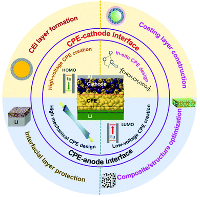
Here, we put a special focus on reviewing the recent progress in stable and intimate interface design between CPEs and electrodes (Scheme 2). The previous understanding and recent developments in cathode–electrolyte and anode–electrolyte interface research are summarized. The interface research mainly includes electrolyte engineering, cathode modification, and process optimization. On the cathode side, the emphasis has been on improving the high-voltage stability of electrolytes and preventing the side reactions at the cathode–CPE interface. On the anode side, the objectives have been to inhibit the dendritic growth of the Li metal anode and to improve the low-voltage stability of CPEs. Simultaneously, examples of improving cathode–CPE and anode–CPE interfaces for applications have been introduced. More importantly, strategies stabilizing the cathode/anode–CPE interfaces synchronously, such as with designs for the structure of CPEs at the molecular level, have been summarized and categorized. Finally, we propose some perspectives and outlooks. With the increasing research on PSSBs, more attention will be focused on the construction of interfaces. We believe that this review can provide some help for the further development of CPEs and promote the future practical application of PSSBs.
2. Construction of the cathode–CPE interface
2.1 Fundamental challenges for the cathode–CPE interface
It should be noted that the cathode–CPE interface plays an important role in obtaining superior PSSBs with high safety, high energy density, and long cycling life.65,66 Generally speaking, the cathodes adopted in PSSBs are the same as those used in liquid LIBs, such as LiFePO4, LiCoO2, and LiNixCoyMnzO2.67,68 Constructing a stable intimate cathode–CPE interface faces the following challenges: (1) the large contact area between the CPE and the cathode gives the CPE less oxidation stability, so that it easily undergoes oxidative decomposition due to the catalysis of transition metal ions or conductive carbon.69–72 The possible mechanism is that the C–H bonds in the polymer are weakened during the charging process and hydrogen atoms are taken away by the anions in the electrolyte salts to form acids. Much worse, the acids that are formed intensify the side reactions on the cathode–CPE interface, degrading their electrochemical performances. (2) The cathode–CPE interfacial contact becomes less compatible due to the volume changes of the cathode during cycling. Furthermore, the poor compatibility can lead to large polarization, which inevitably establishes a space charge layer at the interface. Due to the uneven charge distribution, stoichiometry variation and structural deformation take place, the internal resistance of the battery further increases.73–76 Therefore, it is necessary to build a stable interface through diverse strategies for modifying the CPEs and cathode materials, as well as process optimization.2.2 Solutions for the cathode–CPE interface: modification of CPEs
The electrochemical performance of PSSBs can be improved through in situ polymerization by different methods. Zhou et al. introduced a succinonitrile (SN)-lithium bis(fluorosulfonyl)imide (LiTFSI)-lithium bis(oxalato)borate (LiBOB)-tri(propylene glycol) diacrylate solid polymer interlayer (SPI) in situ at the Li1.5Al0.5Ge1.5(PO4)3 (LAGP)–cathode interfaces with C8H12N4 as an initiator (Fig. 1a).86 The SPI could flow and infiltrate into voids and cracks at the solid–solid interfaces and then solidify in situ after the heat treatment, significantly reducing the interfacial resistance and improving the interfacial lithium-ion transport. The borate species-enriched cathode–electrolyte interphase (CEI), generated by the interaction of BOB− and the M–O bond of the cathode to reduce the break-down of LiBOB, is believed to inhibit the continual degradation of the electrolyte at high voltage and stabilize the interfaces between the SSEs and cathodes, which can widen the electrochemical window up to 4.8 V. Therefore, a LiNi0.8Co0.15Al0.05O2/Li cell showed a high capacity of 200 mA h g−1 at 0.1 C and stable cycling beyond 100 cycles at 0.5 C with a capacity retention of 80% at room temperature. Using a different method, Chen et al. developed an in situ method via an ultraviolet (UV)-induced cross-linking strategy to prepare interpenetrating networks of single-ion conductive polymer electrolytes (IN-SCPEs) for PSSBs (Fig. 1b).87 The resultant IN-SCPEs, consisting of 4-styrenesulfonyl-(trifluoromethylsulfonyl)imide, poly(ethylene glycol)methyl ether acrylate, and poly(ethylene glycol) dimethacrylate polymer with polymerizable ethylene carbonate as the organic filler, presented a superior electrochemical stability window up to 5.3 V vs. Li+/Li and had good interfacial compatibility with electrodes. The significantly enhanced electrochemical stability benefits from the similar structures of the two networks in IN-SCPEs, and the polymer chains are miscible and highly entangled to hinder the decomposition. Therefore, LiFePO4/IN-SCPEs/Li cells delivered stable cycling performance at ambient temperature with the capacity retention of 92.5% at 0.2 C after 100 cycles and 83.2% at 0.5 C after 200 cycles.
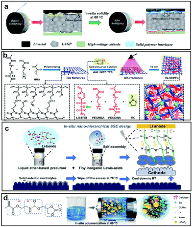 | ||
| Fig. 1 (a) Schematic illustration of SPI modification in high-voltage SSBs. Reproduced with permission.86 Copyright 2020, The Royal Society of Chemistry. (b) Schematic illustration of the synthesis of IN-SCPEs. Reproduced with permission.87 Copyright 2020, American Chemical Society. (c) Schematic illustration of the fabrication of nano-hierarchical SPEE. Reproduced with permission.89 Copyright 2021, Wiley-VCH. (d) CUMA monomer and structural composition of the CPE. Reproduced with permission.90 Copyright 2020, American Chemical Society. | ||
Thermal stability is an important factor affecting the interfacial properties between the electrodes and electrolytes. Transition metals in the cathodes and the conductive carbon can catalyze the decomposition of composite electrolytes at high voltage, inevitably generating some gas which will diffuse to the anode side and react with the Li metal. During this reaction process, a lot of heat will be generated thus inducing a low thermal stability. Compared with PEs, CPEs have a better thermal stability as the homogeneously dispersed inorganic filler can act as the rigid backbone to prevent the quick heat conduction into the matrix, thereby relieving the thermal degradation of active materials.88 However, the challenges of finding effective strategies to reduce heat generation remain in achieving safe operation over a wide temperature range. Therefore, it is important to enhance the thermal stability of CPEs. Zhang et al. demonstrated a nano-hierarchical quasi-solid-state polymer electrolyte with a solid eutectic mixture for interface protection on the surfaces of the cathodes via the in situ polymerization of traditional liquid ether-based precursors with inorganic AlI3 Lewis-acid additives (Fig. 1c).89 The nano-hierarchical solid-state poly-ether electrolyte (SPEE) impeded the dissolution and transfer of transition metal from the cathode side to the surface of the Li anode and presented highly compatible electrolyte/electrode interfaces from thermodynamic/electrochemical aspects. Therefore, LiFePO4/SPEE/Li batteries displayed an outstanding long lifespan with a capacity retention of 85% after 1200 cycles at 1 C, while LiCoO2/SPEE/Li batteries displayed a capacity retention of 91.7% over 200 cycles with high Coulombic efficiencies. Furthermore, Chen et al. fabricated a deep eutectic solvent-based, in situ polymerized solid electrolyte containing (2-((2-oxo-1,3-dioxolan-4-yl) methoxy) carbonylamino)-ethyl methacrylate (CUMA), SN, and two kinds of lithium salts, with a superior polymerization conversion of 99.8% (Fig. 1d).90 It was observed to have reinforced interfaces and high-voltage durability, owing to its high polymerization conversion, stable CEI film formation, and thermodynamic stability. When coupled with a 4.6 V LiCoO2 cathode, the cell based on the as-investigated electrolyte delivered a superior cycling performance with 82.4% capacity retention after 100 cycles. Overall, the in situ polymerization of CPEs is an excellent choice for improving the interfacial stability based on compatibility and thermal stability.
According to the theory of molecular orbitals, a lower HOMO energy for a polymer implies a higher voltage stability. Poly(vinylidene fluoride-co-hexafluoropropylene) (PVDF-HFP) is the most widely studied polymer, which has a high dielectric constant and high-voltage electrochemical stability. Li et al. selected PVDF-HFP as their polymer substrate, an ionic liquid as the organic filler, methoxy polyethylene glycol acrylate as the polymerization monomer, and ethoxylated trimethylolpropane triacrylate as the cross-linking agent and the cross-linked CPEs were cured using UV light (Fig. 2a and b). This designed CPE showed an excellent ionic conductivity at room temperature, robust mechanical strength, good interface compatibility, and a wide electrochemical stability window of about 5 V (Fig. 2c).93
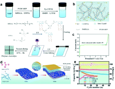 | ||
| Fig. 2 (a) Schematic illustration of the reparation process and reaction mechanism of an ionogel polymer electrolyte. (b) Schematic diagram of the conduction mechanism for lithium ions in the electrolyte. (c) Linear sweep voltammetry (LSV) curve of a CPE. Reproduced with permission.93 Copyright 2021, American Chemical Society. (d) Schematic representation of the detailed synthesis process for CSE and the assembly process of SSBs. (e) Cycling performances of the LiNi0.6MnO.2Co0.2O2/Li cell with various electrolytes at the 0.1C rate. Reproduced with permission.94 Copyright 2021, Wiley-VCH. | ||
Apart from the above-mentioned design, dual salts introduced into cathode CPEs also promote high voltage stability of the electrolyte. Xie et al. explored a boron, fluorine-donating electrolyte which was composed of PVDF-HFP, LiTFSI, LiBOB, and Li7La3Zr1.4Ta0.6O12 (LLZTO), leading to a stable interface between the high-voltage cathode and the ultrathin composite solid electrolyte (CSE) (Fig. 2d).94 The addition of LiBOB could reduce the highly resistive LiF content in the solid–liquid electrolyte interphase (SLEI), which reinforces interfacial thermodynamic stability. Meanwhile, the decomposition reaction of LiBOB to LixBOyFz further decreases the interface diffusion resistance. The resulting low-resistance and highly stable SLEI enabled excellent cycling stability and rate capability of the LiNi0.6MnO.2Co0.2O2/CSE/Li cell under high-voltage conditions (Fig. 2e). In short, the construction of high-voltage CPEs widens the electrochemical window and improves the cycling stability without contributing additional internal resistance.
2.3 Cathode material modification
Chen et al. employed in situ differential electrochemical mass spectrometry to reveal that the surface catalytic effect of LiCoO2 is the root cause of the unexpected H2 gas release of poly(ethylene oxide) (PEO)-based PSSBs at 4.2 V (Fig. 3a).100 The H2 release is due to the crossover effect of trifluoromethanesulfonimide (HTFSI), which is generated on the cathode side, and diffuses to the anode to react with the Li metal. A stable solid electrolyte LATP coating on the surface of LiCoO2 can mitigate such a surface catalytic effect and therefore extend the stable working voltage to >4.5 V (Fig. 3b). With deep research, it has been discovered that the conductive carbon in the cathode also accelerates the decomposition of the electrolyte, but the conventional chemical coating cannot achieve simultaneous coating of the conductive agent and the cathode material. Therefore, the exploration of new coating methods is very important. Sun et al. did a series of studies to simultaneously solve the problem of surface catalysis of the conductive agent and the cathode material by atomic layer deposition (ALD).101,102 At first, a solid-state electrolyte layer of lithium niobium oxide (LNO), which will be stable at high voltage, is coated on the LiNi0.8Mn0.1Co0.1O2 (NMC811) electrode surface for stabilizing the NMC811/PEO-LiClO4/LLZTO CPE interface (Fig. 3c). Chemomechanical degradation and oxygen release are inhibited by the LNO coating, and the decomposition reaction of the CPE is mitigated, which results in a stable cathodic electrolyte interphase and good performance of the NMC811/PEO solid polymer battery (Fig. 3d and e). Secondly, a thin ALD-derived lithium tantalate coating on high-voltage LiCoO2 and conductive carbon demonstrated enhanced cycling performance compared with a LiCoO2 coating (Fig. 3f and g), indicating that the conductive carbon–CPE interface helps reduce the electrochemical oxidation of PEO-based CPEs.
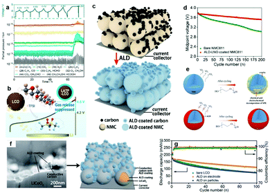 | ||
| Fig. 3 (a) Voltage profile and corresponding mass signals of the LATP-LiCoO2/PEO-LiTFSI/Li cell at 60 °C cycled in the voltage ranges of 3.0–4.2, 3.0–4.4, and 3.0–4.6 V for two cycles with a constant current of 27.4 mA g−1 at 60 °C. A final charging to 4.8 V led to the cell failure, and an abrupt voltage drop can be observed during the discharge process. (b) Schematic illustration of the mechanism of gas release. Reproduced with permission.100 Copyright 2020, American Chemical Society. (c) Schematic illustration showing the ALD-LNO coating on the NMC811 electrode. (d) The midpoint voltage evolution of two SSBs over 200 cycles. (e) Schematic illustration of the ALD-LNO coating effect on NMC811 SSBs with PEO-based CPEs. Reproduced with permission.101 Copyright 2020, Elsevier. (f) A SEM image in backscattered electron mode after 20 cycles of ALD-LNO (thickness of about 10 nm) coating on both conductive carbon and LiCoO2 particles after focused ion beam cutting, and its schematic illustration. (g) Comparison of cycling performances of LiCoO2 with and without ALD coatings. Reproduced with permission.102 Copyright 2020, The Royal Society of Chemistry. | ||
Compared with the inorganic coating layer, the organic layer has higher flexibility to relieve volume expansion without breaking and achieve better contact with CPEs to decrease the interfacial resistance and enhance the cycling stability of PSSBs. Cui et al. modified the LiCoO2 surface by introducing a thin layer of electrochemical-oxidation-resistant poly(ethylcyanoacrylate) (PECA) in PEO-lithium difluoro(oxalato)borate (LiDFOB)-SN CPEs through the in situ polymerization method.103 After LiCoO2 was coated with PECA, the conduction band of LiCoO2 clearly shifted toward higher energy, and the valence band shifted toward lower energy (Fig. 4a), which increased the oxidation stability of the LiCoO2 surface. The coating layer significantly suppressed the continuous decomposition of the LiDFOB salt in PEO electrolyte and decreased the interfacial impedance, thus enhancing cycling stability (Fig. 4b and c). Further improving the ionic conductivity of the organic layer is the key to improving the Coulombic efficiency and cycle life. For this reason, Li et al. deposited an electronic and ionic dual conductive polymer (DCP) coating layer on LiFePO4 to maintain its structural integrity via buffering the internal stress during lithiation/delithiation (Fig. 4d).104 The crosslinking, coordination, and hydrogen-bonding effects endowed the DCP with high elastic modulus, intimate contact at the interface and fast electronic/ionic transportation (Fig. 4e). In conclusion, it is very necessary to design different coating layers in view of the characteristics of different cathode materials to improve their electrochemical performance.
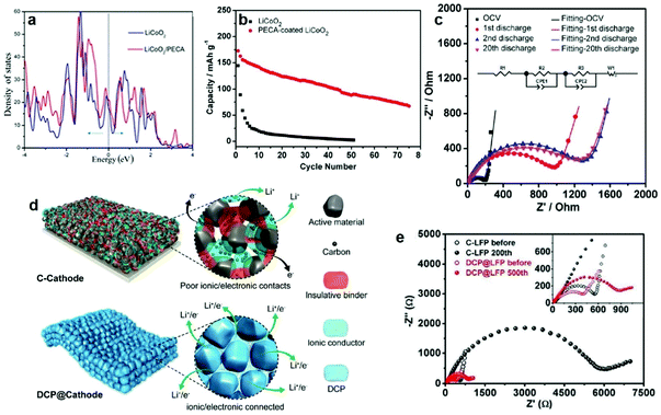 | ||
| Fig. 4 (a) Total density of states of the interface and surface structure of LiCoO2 with and without a PECA coating. (b) Cycling performances of LiCoO2/PEO-LiDFOB/Li and PECA-coated LiCoO2/PEO-LiDFOB/Li cells at 80 °C. (c) Measured and simulated results of impedance plots for PECA-coated LiCoO2/PEO-LiDFOB/Li cells at different cycle states. Inset is the corresponding electrical equivalent circuit. Reproduced with permission.103 Copyright 2017, The Electrochemical Society. (d) Schematic illustration of Li+/electron transportation in a DCP-based cathode compared with a cathode with carbon. (e) Fitted Nyquist plots of the fresh cathodes and ones after cycling, with the inset showing an enlargement of the high-frequency region. Reproduced with permission.104 Copyright 2020, Wiley-VCH. | ||
Interface instability that stems from the highly catalytic Ni-rich layered cathode is the key obstacle to the development of high-voltage PSSBs. Wei et al. designed a multifunctional polyamide-based quasi-solid electrolyte (PAM-QSE) with ethylene and ethyl methyl carbonate as organic fillers to construct a robust CEI on their Ni-rich cathode (Fig. 5a).109 The CEI structure comprises high antioxidative amide organic species and rich antioxidative N–C![[double bond, length as m-dash]](https://www.rsc.org/images/entities/char_e001.gif) O, which greatly prevents the catalytic decomposition of the electrolyte and suppresses the surface degradation of active cathode materials.
O, which greatly prevents the catalytic decomposition of the electrolyte and suppresses the surface degradation of active cathode materials.
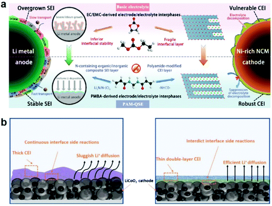 | ||
| Fig. 5 (a) Design strategy for PAM-QSE: schematic illustration of the interface stabilization mechanism for PAM-QSE. Reproduced with permission.109 Copyright 2020, Elsevier. (b) The thick CEI and the thin double-layer CEI formed in CPEs. Reproduced with permission.110 Copyright 2021, Elsevier. | ||
The formation of the CEI by electrochemical polymerization has great potential for large-scale production. Cui et al. synthesized a cyano-reinforced CPE based on in situ copolymerization of 2-cyanoethyl acrylate and poly(ethylene glycol) methyl ether acrylate in the LiTFSI-LiDFOB-LLZTO precursor.110 The –C![[triple bond, length as m-dash]](https://www.rsc.org/images/entities/char_e002.gif) N rich and LiF-rich stable CEI with a low negative electrostatic potential could strongly interact with LiCoO2 and effectively suppress the damage of ethylene oxide segments during the charging process (Fig. 5b). This type of CEI can further improve the compatibility of cathode–CPEs and stable high-voltage CPEs, as well as suppress the destruction of CPEs. In summary, the construction of such an in situ CEI film with its simple operation, good interfacial contact, and stable interface properties will become the star of the commercialization process.
N rich and LiF-rich stable CEI with a low negative electrostatic potential could strongly interact with LiCoO2 and effectively suppress the damage of ethylene oxide segments during the charging process (Fig. 5b). This type of CEI can further improve the compatibility of cathode–CPEs and stable high-voltage CPEs, as well as suppress the destruction of CPEs. In summary, the construction of such an in situ CEI film with its simple operation, good interfacial contact, and stable interface properties will become the star of the commercialization process.
2.4 Process optimization
According to the different electrolytes and cathode materials, different strategies have been developed, such as bilayer tape casting, directional freezing polymerization, etc. Wang et al. developed a cathode-supported solid electrolyte membrane framework composed of PEO-PVDF-LiTFSI-Al2O3 to enhance interfacial contact in PSSBs.113 Compared with the separate solid electrolyte film, the solid electrolyte is directly cast on the cathode layer to enhance the wetting ability of the solid electrolyte on the cathode and reinforce the interfacial adhesion (Fig. 6a). Therefore, the fabricated LiFePO4/Li cathode-supported CPEs could deliver discharge capacities of 125 mAh g−1 (0.1 C rate) and 167 mAh g−1 (0.1 C rate) at 30 and 50 °C, respectively, which are better than when using traditional separated CPEs. Using a different approach from the bilayer tape casting method to reduce the randomness of the ion pathways, Grant et al. investigated an innovative directional freezing and polymerization method to create anisotropic transport networks.114 A 600 μm hybrid cathode comprising vertically aligned NMC811-rich channels filled with the LiTFSI-poly(ethylene glycol) methacrylate-1-methyl-1-propylpyrrolidinium bis(trifluoromethanesulfonyl) imide electrolyte was fabricated with kinetically favorable ion transport characteristics in PSSBs (Fig. 6b). In this design, there are unidirectional Li+ transport pathways and a homogeneous Li+ concentration throughout the cathode thickness. The vertically aligned structure allowed the efficient use of active materials in a practical thick electrode format.
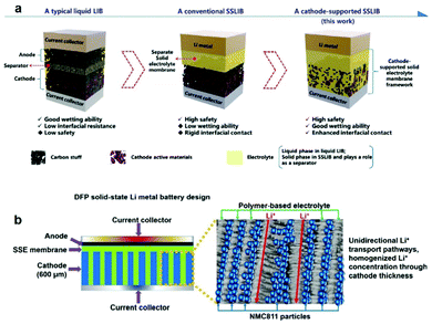 | ||
| Fig. 6 (a) Schematic illustration of the novel cathode-supported configuration in comparison with a conventional rigid SSB and a typical liquid-electrolyte lithium-ion battery. Reproduced with permission.113 Copyright 2018, The Royal Society of Chemistry. (b) The solid-state lithium metal battery (SSLMB) design with an anisotropic cathode structure (600 μm thick) comprising vertically aligned NMC811-rich pillars surrounded by a polymer-based electrolyte. Reproduced with permission.114 Copyright 2021, Wiley-VCH. | ||
Based on the different properties of CPEs and electrode materials, the methods for hot pressing are also different. Deng et al. selected a hot-pressing strategy to introduce a polyamide 6 microfiber non-woven fabric into a PEO-LiTFSI matrix to form CPEs (Fig. 7a–e).118 After hot pressing, the combination between polyamide and PEO-LiTFSI was tight and without boundaries, which was good for the electrochemical performance. Subsequently, Guo et al. reduced the porosity of LLZTO and polyvinylidene fluoride (PVDF) composite electrolytes by hot pressing, achieving a high ionic conductivity (1.08 × 10⁻⁴ S cm−1) at 60 °C (Fig. 7b).119 As shown in Fig. 7c, the polarization of charge–discharge curves is very small after hot pressing, indicating the low interfacial impedance of the cell. Hot pressing further improves the electrochemical performance, with a high-capacity retention of 86% reported, even after 200 cycles (Fig. 7d). In short, process optimization is as important as CPE/electrode material design. By combining them together, we can move toward industrialization at a faster pace.
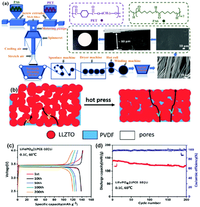 | ||
| Fig. 7 (a) Schematic illustration of the preparation of the polyamide 6 microfiber non-woven fabric. Reproduced with permission.118 Copyright 2020, Elsevier. (b) Schematic illustration of the influence of density on the Li+ transport in solid electrolytes with a high filler content. (c) Typical charge–discharge curves and (d) the cycling performance of an LiFePO4/CPEs/Li battery at 0.1 C. Reproduced with permission.119 Copyright 2020, The Royal Society of Chemistry. | ||
Just as the temperature and pressure have an important effect on the preparation of CPEs, cycling conditions (stacking pressure and temperature) have a significant impact on the performance of PSSBs, especially on the interfacial contact and dendrite growth. However, based on the advantages of CPEs in improving ionic conductivity, mechanical strength, and thermal stability compared to polymer electrolytes, the cycling conditions become mild. Auxiliary implementation strategies on electrodes and CPEs further improve the electrochemical performance.
3. Construction of the Li metal anode–CPE interface
3.1 Basic challenges for the Li metal anode–CPE interface
In PSSBs, CPEs can provide one of the most promising approaches to use the ‘holy grail’ Li metal as the anode in practical PSSB applications. The use of lithium metal can greatly increase the energy density of PSSBs, but the interfacial issues between lithium metal and CPEs still remain. Firstly, the periodic expanding and shrinking of lithium metal during cycling causes deterioration of the already poor mechanical contact between lithium and the CPE. Secondly, the instability of the electrolyte at a reductive potential during the Li exfoliation process will cause side reactions. The reaction products will further corrode lithium metal, resulting in poor interfacial contact and attenuated PSSB performance. All of the above will cause the re-distribution of charge at the Li–electrolyte interface to bring about the formation of Li dendrites.120,121The growth of dendrites mainly occurs at the CPE–Li metal interface. Analyzed by the Chazalviel model, the anionic concentration near the Li anode drops to zero at Sand's time at a high current density. However, the different behaviors of anionic and cationic concentrations will result in excess positive charge on the Li anode, which generates local space charges united with large electric fields. This situation can lead to the growth of lithium dendrites inducing an unstable interface. In contrast, when the current density is reduced, the concentration gradient is lower than that in the high current density case, and the dendrites start to grow after a period.122,123 In the CPEs, the lithium salts with a low Li transference number would result concentration gradients of anions and cations, so choosing a lithium salt with high Li transference number is effective in suppressing dendrites. From a thermodynamic point of view, Li dendrites originate from the effect of surface tension to induce uneven Li deposition and dissolution. Therefore, it is important to reduce the effective current density and improve the mechanical strength of the electrolyte to inhibit the growth of dendrites and achieve a long cycle life for PSSBs.124 On the one hand, from the perspective of the electrolyte, designing CPEs with different fillers to accomplish high mechanical strength is very necessary. This is because filler-filled CPEs with 3D structures and high mechanical strength can induce uniform deposition of Li+ and slow down the growth rate of Li dendrites. The homogeneity of CPEs plays an important role in regulating Li deposition, mechanical tensile strength, and thermal/electrochemical stability. The inhomogeneity of CPEs leads to the generation of lithium dendrites, which can be solved by regulating the viscosity and compatibility of their ingredients. The strategies in the literature are mainly divided into two aspects: (1) electrochemical deposition including electrospinning and electrophoretic deposition are effective ways to improve the homogeneity of CPEs by adjusting their viscosity.125 (2) The in situ polymerization method with compatibility interface is another way to improve CPE uniformity.26 Furthermore, it is important to construct a low-voltage stable CPE to reduce side reactions of the electrolyte with Li by using the interaction between polymer electrolyte and filler. On the other hand, the modification of lithium metal including surface tension and specific surface area is another effective way to suppress dendrite growth. Lithiophilic coating layers, which can be organic, inorganic, or composite materials, can ease the structural stress on the Li surface to induce uniform deposition of lithium. Li hosted in a 3D structure or Li composite anode could have a smaller nucleation overpotential, easily inducing the nucleation of lithium and alleviating volume changes, which is conducive to long-term cycling performance.126–128
3.2 Solutions for the Li–CPE interface: modification of CPEs
The mechanical strength and compatibility of CPEs can be enhanced by introducing fillers/skeletons into polymer structures. Fu et al. developed a CPE using PEO-LiTFSI as a polymer matrix and LATP and glass fiber (GF) as reinforcement fillers (Fig. 8a).139 Their LATP-GF/PEO-LiTFSI composite electrolyte offered high tensile strength and high effectiveness towards suppression of lithium dendrite growth, and demonstrated good interface contact. As shown in Fig. 8b, PEO-LiTFSI alone exhibited poor load-bearing ability with a low tensile strength of around 0.06 MPa and a low Young's modulus of around 0.26 MPa. Meanwhile, their LATP-GF/PEO-LiTFSI demonstrated a high tensile strength of 33.1 MPa and a high Young's modulus of 1.62 GPa. The outstanding tensile performance of the LATP-GF/PEO-LiTFSI composite is clearly attributable to the reinforcement effect of GF. It is not a connection at the chemical bond level, and the interface contact is not perfect, however. Hence, it is essential to balance adhesion between Li/CPE and mechanical properties through a particular design. Ni et al. developed a high quality CPE by using lignin nanoparticles (LNPs) to regulate the pore characteristics of a cellulose nanofibril (CNF) film template.140 The synthesis process is shown in Fig. 8c. Firstly, the high accessible specific surface area of the nanopores and high amount of free hydroxyl groups (without hydrogen bonding) in the CNFs are responsible for the fast infiltration of the LLZO precursors. Next, calcination leads to a closer contact of the LLZO with the substrate. Finally, the polymer electrolyte penetrates into the 3D framework structure to form a thin, flexible, and conductive CPE. The LNP-regulated CNF-film-templated LLZO membranes significantly increase the critical value of the current density and suppress the growth of lithium dendrites. The outstanding cycling stability of the resulting batteries is due to the improved interfacial properties of the LNP-regulated CNF film templated LLZO-PEO CPEs. What's more, Xie et al. designed elastic epoxy polymers including a hard segment (HS), a chain extender, and a soft segment (SS) (Fig. 8c).141 Different formulas of the precursors have different mechanical properties. When 10 wt% zinc octoate (Zn(Oct)2) is introduced into the system, there will be stronger interactions between the HS and SS. Due to the extra intermolecular interactions between Zn2+ and the obtained elongation, the Young's modulus can be further enhanced to 16.61 MPa. Moreover, the in situ formation of an LiZn alloy layer between Zn(Oct)2 and Li can help to improve interface compatibility (Fig. 8d and e).
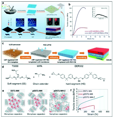 | ||
| Fig. 8 (a) Schematic illustration of the fabrication of the LATP-GF/PEO-LiTFSI structural electrolyte and an acidified carbon fiber (ACF)/LATP-GF/PEO-LiTFSI/Li cell. (b) Typical tensile stress–strain curves of PEO-LiTFSI, LATP-GF/PEO-LiTFSI, and ACF/LATP-GF/PEO-LiTFSI. Reproduced with permission.139 Copyright 2021, American Chemical Society. (c) Schematic illustration of the LNP-regulated CNF-film-templated LLZO membranes and the LNP-regulated CNF-film-templated LLZO-PEO CSE. Reproduced with permission.140 Copyright 2021, Elsevier. (d and e) Schematic illustrations of designed elastic epoxy polymers and (f) the corresponding stress–strain curves. Reproduced with permission.141 Copyright 2021, American Chemical Society. | ||
Combining cross-linked polymers with inorganic materials via in situ strategies can result in a greater improvement in electrochemical performance, because the interface contact and ionic conductivity are greatly enhanced through in situ methods. Park et al. used an in situ UV curing method to obtain CPEs with high mechanical toughness, which were composed of cross-linking polymers and exfoliated clay nanosheets.142 As shown in Fig. 9a, the precursor is injected directly into the cathode and irradiated with UV light. The liquid phase precursor infiltrates into the voids between the cathode active materials (LiCoO2), which is beneficial to the transport of Li+ ions after cross-linking. Furthermore, the high mechanical properties of the CPEs together with the exfoliated clay nanosheets can inhibit the growth of dendrites after UV curing. The cell using the UV-cured CPEs showed a stable voltage profile with slight polarization for more than 500 h at 0.5 mA cm−2 (Fig. 9b). Above all, this design decreased the internal resistance, leading to an extended cell lifetime. The inorganic material formed in the polymerization process had more uniform particles and a more uniform particle distribution, together with better mechanical strength and interfacial contact. Then, Lin et al. synthesized fluorinated bifunctional CPEs (FB-CPEs) by photo-controlled radical polymerization between polyethylene glycol methyl ether acrylate and 2,2,3,4,4,4-hexafluorobutyl methacrylate (Fig. 9c).143 Li–F interactions were established in situ by rational incorporation of -CF2- and -CH2CH2O- segments (Fig. 9d). This process can generate uniform lithium electrodeposition near the Li anode because of the concerted transport of lithium ions paired with TFSI− in the solvation sheath, eventually suppressing lithium dendrites. As shown in Fig. 9e, the cells containing FB-CPEs displayed stable cycling for more than 1500 h and exhibited superior resistance to premature cell failure resulting from dendrite growth. In contrast, cells containing non-fluorinated CPEs showed a gradual decrease in voltage and short-circuited at ∼100 h, suggesting an unstable flux of Li+ ions in the polymer matrix. By adjusting the length of the polymer monomer, the interfacial contact and mechanical strength of the electrolyte could also be changed. Moreover, Chen et al. addressed the interface issue by adjusting the length of ethyoxyl (EO) chains to change the coordination mode between EO groups and lithium ions in a facile in situ polymerization (Fig. 9f).144 Compared with the copolymer with long EO chains, the one with shorter EO chains led to freer lithium migration. This comparison reveals that the semi-closed coordination mode plays a key role in the improvement of CPE performance (Fig. 9g).
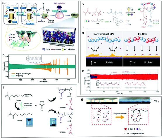 | ||
| Fig. 9 (a) Schematic illustration of the preparation of the CPEs. (b) Galvanostatic cycling curves of Li/Li symmetric cells with liquid electrolyte and a CPE. Reproduced with permission.142 Copyright 2020, Wiley-VCH. (c) Schematic illustration of the synthesis of FB-CPEs by visible-light-driven, photo-controlled radical polymerization. (d) Illustration of different Li deposition behavior in Li/Li symmetric cells with a conventional CPE and an FB-CPE. (e) Voltage profile comparison of FB-CPE versus non-fluorinated CPE as a function of time, wherein each half-cycle lasted for 3 h at a current density of 0.1 mA cm−2. Reproduced with permission.143 Copyright 2021, Wiley-VCH. (f) Schematic illustration of the synthesis route to synthesize CPEs. (g) Schematic illustration of in situ polymerization in a cell. Reproduced with permission.144 Copyright 2020, Elsevier. | ||
Introducing 3D substrate/Li ion conductors into CPEs can give them high-mechanical strength to buffer the volume expansion as well as the ability to induce uniform deposition of Li+ ions. Based on the 3D frame structure, Yang et al. designed CPEs with PEO-LiTFSI with alginate as an additive filler possessing a high-strength 3D porous structure. The structure is connected by hydrogen bonds between the oxygen atoms in the PEO matrix and the alginate fiber (AF) skeleton (PEO@AF). This greatly increases Li+ anchor points and provides more Li+ migration pathways, leading to the enhancement of Li+ conduction and interfacial stability between the CPE and the Li anode (Fig. 10a).145 As shown in Fig. 10b, the tensile strength of PEO@AF CPEs is 3.71 MPa, which is higher than for PEO CPEs, and PEO-5% LLZTO CPEs. The much better mechanical properties of the PEO@AF CPE membrane are mainly due to the abundant oxygen-containing groups in alginate macromolecules and the 3D porous structure of the AF membrane. Unlike the 3D skeleton membrane, Tang et al. used 3D coral-like Li6.4La3Zr2Al0.2O12 (LLZO) to build 3D interconnected frameworks in a PVDF matrix (Fig. 10c).146 The tensile strength of PVDF/LiClO4 CPEs is improved by the addition of commercial LLZO particles, and it is further improved by adding 3D-LLZO (Fig. 10d). This reinforced mechanical property of PVDF/3D-LLZO is likely to be related to the unique coral-like structure of 3D-LLZO, which is conducive to the homogeneous dispersion of the fillers within the polymer matrix. As shown in Fig. 10e, the Li/PVDF-3D-LLZO-5%/Li cell gave the minimum polarization voltage (∼100 mV) compared with the others. These results indicate that such 3D coral-like LLZO/PVDF composite electrolytes are relatively more effective for regulating lithium deposition and suppressing lithium dendrite growth, while the flexible 3D-architecture of the CPEs enables steady cycles of lithium plating/stripping over 200 h without a short circuit. To sum up, whether it is a cross-linked structure or a 3D structure, the physical properties of the electrolyte are changed to achieve good fusion with lithium metal.
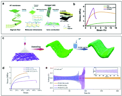 | ||
| Fig. 10 (a) The preparation process for the PEO@AF CPE. (b) Stress–strain curves of three CPE membranes. Reproduced with permission.145 Copyright 2020, American Chemical Society. (c) Schematic illustration of the preparation procedures for the 3D coral-like LLZO/PVDF CPEs. (d) Mechanical tensile stress–strain curves of PVDF/3D-LLZO-5%, PVDF/P-LLZO-5%, and PVDF/LiClO4 at room temperature. (e) Voltage profiles of Li/PVDF-P-LLZO-5%/Li, Li/PVDF-LiClO4/Li, and Li/PVDF-3D-LLZO-5%/Li symmetric cells at room temperature. The inset in (e) shows enlarged voltage profiles from the 40th to the 70th hour. Reproduced with permission.146 Copyright 2020, American Chemical Society. | ||
Specific examples are as follows. Huang et al. designed a quasi-double-layer composite polymer electrolyte (QDL-CPE) by introducing propylene carbonate (PC) and diethylene glycol dimethyl ether (DGM) into a PVDF-HFP-LiTFSI-Li7La3Zr2O12 (LLZO) matrix (Fig. 11a). The nucleophilic substitution reaction between the organic filler DGM and PVDF increases the reduction stability of the electrolyte on the anodic side, which was verified by the density functional theory (DFT) calculation.65 How do inorganic fillers affect the low-voltage interfacial stability? Zhang et al. designed a CPE consisting of poly(ethylene oxide), LiTFSI salt, and SiO2 inorganic fillers in a polymer electrolyte (PSPE), which showed good reductive stability with a Li metal anode.150 The uniform Li-ion flux is provided by the Lewis acid–base interaction between the silica aerogel and TFSI−, and PSPE can block the Li dendrite growth due to homogeneous Li deposition. The production steps for the double-layer polymer electrolyte are shown in Fig. 11b, and involved dip casting and photocuring the precursor solutions of PSPE and poly(vinylethylene carbonate)-ionic liquid polymer electrolyte (PIPE) on a finely-polished Teflon support. From the scanning electron microscope (SEM) image in Fig. 11c, PSPE and PIPE have the same thickness and good contact in the double layered structure without increasing the interfacial resistance. The Li/PSPE/Li battery displayed a steady and low overpotential for over 1000 h at a current density of 0.05 mA cm−2 for a fixed capacity of 0.1 mAh cm−2. PSPE blocks Li dendrite growth with homogeneous Li deposition. The uniform Li-ion flux is provided by the Lewis acid–base interaction from silica aerogel and TFSI−. To further improve the compatibility of polymers, Shen et al. synthesized an asymmetric self-standing LLZO-supported composite polymer electrolyte (LCPE) with polypropylene carbonate (PPC) as the anode CPE and PVDF-HFP as the cathode CPE. The controllable degradation of the PPC layer establishes a stable interface between the electrolyte and the Li metal. LCPE was embedded in a 3D blow-spun Li7La3Zr2O12 (LLZO) framework (Fig. 11d).151 The function of LLZO is to provide continuous Li+ transformation channels and widen the electrochemical window because of the Lewis acid–base interaction. As shown in Fig. 11e, a LiFePO4/Li battery with LCPE exhibited flat charge/discharge voltage profiles and a high initial discharge capacity (140.0 mAh g−1) at 50 mA cm−2. Therefore, the establishment of a low-voltage stable interface follows two principles. First, the polymers have a high LUMO energy according to the theory of molecular orbitals. On this basis, the selected fillers can interact with polymers to widen the electrochemical window and improve the good interfacial stability.
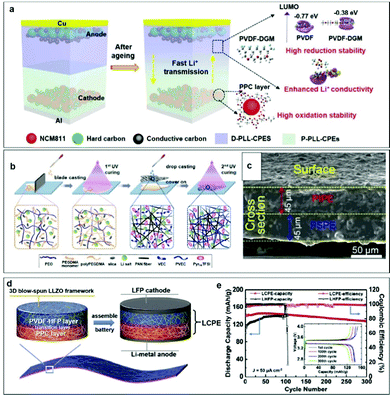 | ||
| Fig. 11 (a) Schematic illustration of the design strategy of QDL-CPEs and PSSBs.65 Copyright 2022, Wiley-VCH. (b) Synthesis procedure for the double-layered polymer electrolyte (DLPE) membrane. (c) SEM image of the cross-section of DLPE. Reproduced with permission.150 Copyright 2020, Elsevier. (d) Schematic illustration of an asymmetric CPE and assembled cell. (e) Cycling performance and typical charge–discharge curves (inset) at a fixed current density of 50 mA cm−2 at 30 °C of a coin-type SSB.151 Copyright 2020, Elsevier. | ||
3.3. Li metal anode modification
Because an interface layer material needs to have high mechanical strength and superior reduction stability, fluoride has won favor. Han et al. employed CuF2 to modify Li metal, which can suppress the growth of Li dendrites and stabilize the electrolyte/anode interface (Fig. 12a).159 The impedance of a modified LiF-rich layer on the Li anode is much lower than that of the bare Li cell after cycling, which indicates that the CuF2 coating layer can effectively suppress the growth of Li dendrites and stabilize the interface of the Li anode with the electrolyte.
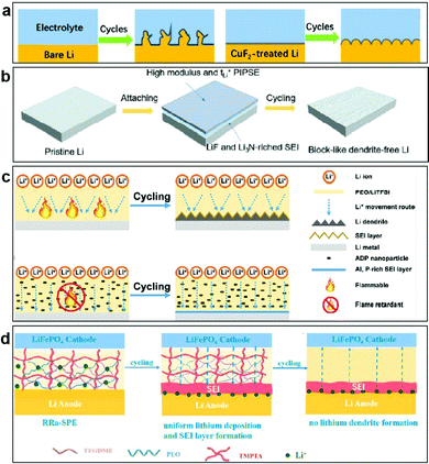 | ||
| Fig. 12 (a) Schematic illustration of Li plating/stripping for the bare Li and CuF2-modified Li electrodes. Reproduced with permission.159 Copyright 2020, American Chemical Society. (b) Schematic illustration of lithium metal surface evolution with PIPSE. Reproduced with permission.160 Copyright 2020, Elsevier. (c) Schematic illustration of Li plating/stripping for ADP-containing CPEs during cycling. Reproduced with permission.161 Copyright 2021, American Chemical Society. (d) Schematic illustration of the changes in the Li electrodes with RRa-CPE during the Li plating/stripping. Reproduced with permission.162 Copyright 2021, Elsevier. | ||
Unlike the coating layer, the artificial SEI is chemically stable which can block the side reactions except the reduction of Li metal, as well as provide stable and uniform lithium-ion transport. Moreover, it has high lithium-ion diffusivity inside the SEI, thus providing a fast diffusion rate at the electrode/SEI interface. Hirano et al. developed novel “polymer-in-plastic salt” electrolytes (PIPSEs) via a high weight ratio of plastic salt (N-ethyl-N-methylpiperidine bis(fluorosulfonyl)imide) to poly(vinylidene fluoride-co-hexafluoropropylene) (PVH), which can wet electrodes and form a compatible SEI film with lithium metal (Fig. 12b).160 Interestingly, Li metal cycled with PIPSEs exhibits a dendrite-free morphology, and the possible mechanism is proposed, involving two aspects. Firstly, the moderate modulus of PIPSEs alleviates the propagation of lithium dendrites. Secondly, the ionically conductive SEI layer composed of Li3N and LiF blocks electrolyte consumption and effectively suppresses lithium dendrites. To further improve the safety, Hu et al. found that halogen-free aluminum diethyl hypophosphite flame retardant (ADP) nanoparticles are decomposed to form an aluminum and phosphorus-rich (Al and P-rich) SEI layer during cycling (Fig. 12c).161 Al and P contents in the SEI film inhibit the growth of lithium dendrites, and the ADP reduces the flammability of the battery, thus enhancing the cycle life of the battery. What is more, Sun et al. proposed bifunctional regular-random dual cross-linking network (RRa)-CPEs. Under the synergistic effect of the regular polymerization skeleton and the random cross-linking network, RRa-CPEs produced a relatively uniform Li+ flux to effectively regulate lithium deposition. Then, during cycling, a stable and homogeneous SEI layer was formed between the RRa-CPE and the Li metal, which promoted uniform lithium deposition (Fig. 12d).162
Various investigations on Li metal anodes have combined the above-mentioned two strategies together. Yu et al. combined PEO with LiTFSI as high performance PSSBs for the silicon–lithium based hybrid anode (Fig. 13a), resulting in a high electroactive contact area, homogenous the Li+ ion flux, and without Li dendrite growth.166 This hybrid anode exhibited stable lithium stripping/plating performance over 1000 h with the average overpotential lower than 100 mV and without any short circuits. As shown in Fig. 13b, the differently lithiated (DF)-Si-Li0.8 anode showed a much lower charge overpotential and a higher specific capacity compared with DF-Si-Li0.5 and DF-Si-Li0.2, indicating that overstoichiometric Li is crucial to achieve the desired electrochemical behavior of the Li metal anode. This provides us with hints that controlling the ratio of lithium is very important for electrochemical performance when designing lithium alloy materials. Using the other method, Cui et al. explored metallic Li in a layered reduced graphene oxide host (Li-rGO) as their anode (Fig. 13c), where the three-dimensional Li significantly reduced the interfacial fluctuations and decreased the effective current density for high-capacity and high-power operations.167 Their anode achieved greatly improved electrochemical performances in comparison with the conventional Li foil, as shown in Fig. 13d. It is apparent that a full cell using the 3D Li-rGO anode demonstrated a much better rate performance compared with its Li foil counterpart at 60 °C. With regard to the long-term cycling stability, over 700 charge/discharge cycles could be achieved using the 3D Li-rGO anode with no degradation (Fig. 13e), whereas the capacity of the Li foil cell decayed rapidly with 200 cycles due to the increasing interfacial impedance, as reflected by the more polarized voltage profiles.
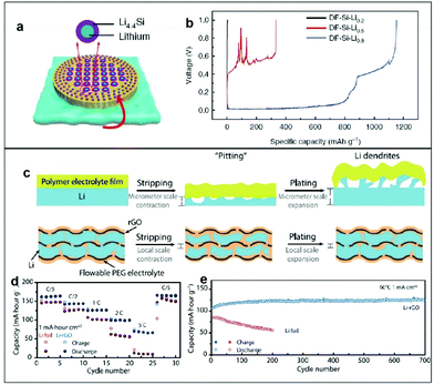 | ||
| Fig. 13 (a) DF-Si powder is mixed with molten Li to form lithium silicide fragments. (b) Li-stripping voltage plateau curves of different DF-Si-Li anodes. Reproduced with permission.166 Copyright 2019, Springer Nature. (c) Schematic illustration of the volume changes and Li stripping/plating of Li foil anode and 3D Li-rGO anode for solid Li batteries. (d) Rate capability of LiFePO4/Li full cells using either 3D Li-rGO or Li foil as the anode at an operating temperature of 60 °C. (e) Long-term cycling performance of batteries with Li-rGO or Li foil at a current density of 1 mA cm−2 and an operating temperature of 60 °C. Reproduced with permission.167 Copyright 2017, Science. | ||
In conclusion, the principle for modifying Li metal anode, including three-dimensional frameworks, lithiophilic treatment, and surface protection, is to adjust the deposition behavior of metallic lithium and inhibit the growth of dendrites.
4. Synchronous cathode/anode–CPE interfacial construction
4.1 New structural designs for CPEs
Based on the previous investigations on solid electrolytes, some novel concepts for designing CPEs, considering both cathode–CPE and anode–CPE interfaces simultaneously are proposed:168–175 (1) constructing gradient CPEs to adapt to the different voltage stability needs of the cathode and anode, (2) adopting polymer electrolyte glue to improve the interfaces between the CPE and the anode/cathode, and (3) using the holes in dura-plate method to improve the mechanical strength and interface properties with the anode/cathode.Chen et al. proposed a new means to enhance interfacial contact by introducing a gradient composite polymer solid electrolyte (GCPE) (Fig. 14a).176 The high LLZTO-content side of the electrolyte exhibits high oxidation resistance (5.4 V versus Li+/Li), making it compatible with a high-voltage cathode material, whereas the LLZTO-deficient side achieves excellent interfacial contact with the Li metal anode, facilitating uniform Li deposition. Compared with the traditional composite solid-state electrolyte materials, GCPE films have the following advantages: (1) continuous changes in composition and structure eliminate all macroscale interfaces, providing excellent “solid interface” compatibility; (2) the two sides of the electrolyte film have different properties and functions, meeting the different needs of the anode/electrolyte and cathode/electrolyte interfaces; and (3) this configuration reduces the residual stress and thermal stress in the interface and ensures favorable mechanical properties of the electrolyte in a fluctuating-temperature environment (Fig. 14b). Thus, the GCPE film avoids phase separation during long-term charge–discharge cycling of the battery, thereby maintaining its stability and improving the safety of the battery. After analysis, this design provides ideas for the design of other polymer systems.
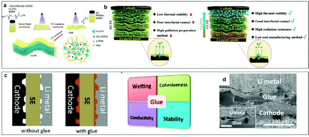 | ||
| Fig. 14 (a) Schematic illustration of the synthesis route for a functional GCPE film. (b) Schematic illustration of the homogeneous CPE and GCPE composite electrolytes. Reproduced with permission.176 Copyright 2021, Wiley-VCH. (c) Schematic diagrams of all solid-state batteries with or without the electrolyte glue, and the general properties required for good electrolyte glues. (d) SEM images of the cross-section of cathode/cured glue/anode cell. Scale bar in the inset is 25 μm. Reproduced with permission.177 Copyright 2019, American Chemical Society. | ||
Chen et al. developed a universal interfacial modification strategy through coating a curable polymer-based glue electrolyte between the electrolyte and electrodes, aiming to address the electrode–electrolyte interfacial contact challenge and thus decrease high interfacial resistance.177 The polymer electrolyte “glue”, is a liquid at room temperature but can be solidified to form a solid electrolyte polymer with increasing temperature. It should meet at least four requirements (Fig. 14c): (1) wettability, i.e., the competency of the glue to permeate the surfaces of the electrode and solid electrolyte. (2) Adhesiveness, the fundamental property of the glue after curing. (3) Ionic conductivity: the glue must be both a good ionic conductor and an electronic insulator. (4) Chemical/electrochemical stability: the glue should be able to maintain its electrochemical stability during cycling within a relatively large potential window without any side reactions with the electrode or the solid electrolyte. As shown in Fig. 14d, the electrolyte glue completely filled the cathode/anode voids, which significantly reduced the interfacial impendence. Strategies for using glue involve only a simple synthesis, are convenient to apply, and are suitable for large-scale production.
In short, the above methods all start with the CPEs. Through the design of new structures, the electrochemical stability, interfacial contact, and mechanical strength of the electrolyte are greatly improved. Moreover, the above structural design methods are simple and easy to implement, which provides guidance for the large-scale application of such electrolytes in the future.
4.2 New strategies at the molecular level
Structural design at the molecular level and adjusting the interactions between molecules are novel strategies that can yield excellent electrochemical performances.178–185 Common strategies mainly include using self-healing materials and synergistic effects in molecules: (1) self-healing materials are designed to repair or inhibit Li dendrites formed by uniform deposition. (2) Synergetic effects between Li+ and anions result in enhanced cycling stability for PSSBs.Self-healing refers to the ability of a material to recover from physical damage, and it mainly occurs in small organic molecules or polymers. Mi et al. obtained a dendrite-free Li anode via a self-healing process at the interface which provided a promising way to prepare high-performance composite solid-state electrolytes.186 The coordination of fluoroethylene carbonate (FEC)-Li+ played a key role in the interface self-healing. Fig. 15a shows the mechanism of the interface self-healing. During Li plating/stripping, FEC is driven to the damaged interface, forming a new LiF-rich layer to cover the damaged spot. This is because the coordination between FEC and Li+ enables the interface self-healing of Li-metal–CPEs, thus preventing the growth of Li dendrites and finally achieving long stable Li deposition. With the interface self-healing effect of FEC-Li+ coordination, the CPEs presented long stable lithium deposition with low interfacial impedance and showed good cycle performance in Li/LiFePO4 all-solid-state cells.
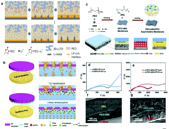 | ||
| Fig. 15 (a) Interface self-healing process in a CPE with the lithium dendrite growth process in a CPE. Reproduced with permission.186 Copyright 2021, Elsevier. (b) Schematic illustration of the Li+ deposition behavior through a standard PP separator and an anion-immobilized PP separator with multiple highly-conductive ion pathways. Reproduced with permission.187 Copyright 2021, Elsevier. (c) Synthesis method and schematic illustration of an asymmetric double layered composite electrolyte (DLCE). Impedance curves of (d) LiFePO4/DLCE/Li and (e) LiFePO4/PEO-hBN/Li cells before and after cycling. Cross-sectional SEM images of (f) LiFePO4/DLCE/Li and (g) LiFePO4/PEO-hBN/Li after cycling for 50 cycles at 25 °C. Reproduced with permission.191 Copyright 2021, Elsevier. | ||
The design of intermolecular interactions is particularly important. Sun et al. improved the electrochemical performance of PSSBs through synergetic effects between Li+ redistribution and anion immobilization.187 As shown in Fig. 15b, a hierarchical-porous-composite solid-state electrolyte consisting of PVDF and LLZTO was coated on one side of a polypropylene (PP) separator to fabricate a composite separator. Firstly, the interactions between PVDF and LLZTO are beneficial to the transportation of Li+, and the subsequent synergetic effects between Li+ redistribution and anion immobilization can effectively redistribute the uneven Li+ flux coming from the insulated PP separator. This facile strategy to modify separators is easily scalable to various composite components with different polymers and solid-state electrolyte powders, which are highly expected to show similar electrochemical performance.
In summary, designing CPEs from the perspective of molecular level or intermolecular interactions can achieve more effective results. Making use of the intrinsic properties of molecules will substantially improve their electrochemical performances.
4.3 Double-layer CPE construction
At present, no single polymer can have a wide enough intrinsic band gap for both dendrite-free plating of a lithium-metal anode and Li+ extraction from an oxide host cathode without electrolyte oxidation in a high-voltage cell during the charging process.188–190 Therefore, double-layer electrolyte construction to enlarge the polymer redox voltage window is necessary for compatibility with a high-voltage cathode and to meet the requirements of high-energy-density PSSBs.For the structural design of polymers, Chen et al. developed an asymmetric CPE with two different layers to simultaneously overcome the interface issues on both the cathode and the anode side. On the cathode side, a polypropylene carbonate (PPC) layer has enough viscosity and flexibility to reduce the interfacial resistance with cathode particles, while on the Li anode side, a PEO layer modified with hexagonal boron nitride (hBN) has fast Li+ ionic conductivity and high mechanical strength to suppress the Li dendrite growth (Fig. 15c).191 As shown in Fig. 15d and e, the charge-transfer resistance of double-layer CPEs is smaller than that of the hBN-PEO layer before and after cycling, which helps the flexible PPC layer to enable close contact between the electrolyte and the cathode. In addition, no obvious gap was detected between the PPC/hBN-PEO and the PPC–cathode interface, and there was no Li dendrite formation at the Li-hBN–PEO interface (Fig. 15f and g), indicating the advantages of the double-layer CPE construction.
In short, constructing a double-layer CPE is a simple way to achieve excellent electrochemical performances. This is because it simultaneously addresses the contradictory requirements for CPEs on the Li-metal side and on the cathode side, giving it great potential for practical applications in PSSBs.
5. Summary and outlook
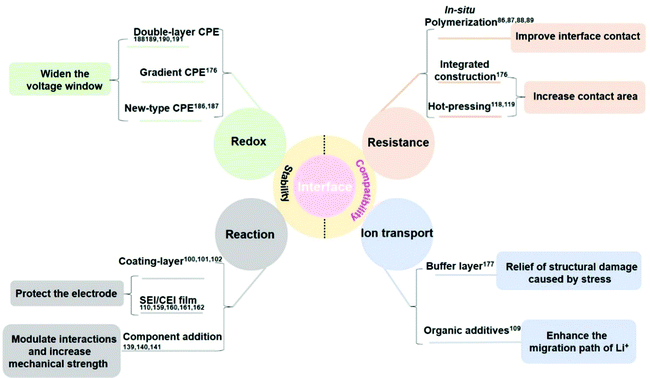
CPEs have been considered as the most promising solid electrolytes to realize future practical applications, due to their remarkable high flexibility, good mechanical strength, and high ionic conductivity. Nevertheless, uncontrollable parasitic reactions between electrodes and CPEs, the volume changes of electrodes during cycling, further exacerbating the poor interfacial contact, and low CPE stability prevent PSSBs from achieving practical applications. It is challenging to construct a stable and intimate electrode–CPE interface to realize high-performance PSSBs. Recently, extensive research efforts have been devoted to designing CPEs to meet the requirements of increased ionic conductivity, decreased interfacial resistance, high antioxidant stability on the cathode side, and suppressing lithium dendrites on the anode side. Note that the modification of electrode materials is equally important to the optimization of CPEs in achieving intimate interfacial contact. This review has summarized the recent research progress on the stability and compatibility of interface design between CPEs and electrodes, to reduce the interface resistance, enhance the continuous ionic transport, improve redox stability, and inhibit the occurrence of interface reactions (Fig. 16). (1) The interface resistance can be reduced by in situ polymerization to improve the interface contact and the uniformity of CPE, and the contact area can be increased using integrated construction/hot-pressing methods. (2) The continuous ionic transport can be achieved by adding a buffer layer as the glue to relieve the stress caused by the contact and structural damage after cycling. Moreover, the interaction between the organic additives and electrodes can enhance the continuous migration of Li ions. (3) The redox stability can be improved by designing CPEs with a novel structure to satisfy the different requirements of the cathode–CPE and Li anode–CPE, like the double-layer or gradient CPEs. It can also be elevated via Lewis acid–base interaction between the polymer chain and additives to change their chemical environment, thus raising the redox stability and further widening the voltage window. (4) The interface side reactions can be inhibited by introducing a coating layer or an in situ/ex situ SEI/CEI layer on the cathode/Li anode interface. Besides, CPEs with high mechanical strength can be obtained through adjusting their ingredients, which can suppress the surface roughness to inhibit lithium dendrite production.To date, although some notable progress has been achieved in the research to improve the CPE/electrode interfacial stability, there are still many challenges. Herein, we put forward prospects for future developments and research directions in the interface field to enhance the electrochemical performance of PSSBs:
(1) To construct an intimate and stable electrode–CPE contact, in situ solidification is a common concept in PSSBs and a relatively simple method for large-scale applications, which improves both the interfacial contact and the safety of PSSBs. How to make good use of this technology and achieve adjustable local solidification is still a great challenge, however. Future expectations of what might be achieved are the following: (1) uniform and dense CEI and SEI films can be directly formed on the surfaces of the cathode and anode by in situ solidification; (2) the intermediate CPE layer can be solidified with a small amount of liquid residue to ensure fast ion conduction; and (3) the structural design can ensure high ionic conductivity and safety, while the precursor can be solidified in situ during heating or energizing. In the acupuncture experiment, the in situ formed stable interfacial layer would block direct contact between the cathode and anode, preventing a short circuit problem.
(2) For improving the ionic conductivity of CPEs, adding plasticizers is an effective method. Besides the main purpose of adding plasticizers, what we hope is that multifunctional effects can be achieved, such as a reaction of the plasticizer with the polymer to widen the electrochemical window or increase the interface contact. For example, a fluorine-based polymer is used as a substrate with a wide electrochemical window, high mechanical strength, and high air stability, although the low ionic conductivity caused by its high crystallinity and the poor interfacial contact have hindered its development. Therefore, an appropriate choice of plasticizer should be made to obtain the best balance. According to the acid–base theory, choosing appropriate small organic molecules with oxygen-containing functional groups can promote their nucleophilic substitution reaction with fluoropolymers. On the one hand, they can reduce the HOMO energy and increase the LUMO energy, thereby broadening the electrochemical stability of the CPEs. On the other hand, the introduction of oxygen-containing functional groups makes the CPE nucleophilic with respect to the electrode material and reduces the interfacial resistance between the electrode material and the electrolyte, thus improving the electrochemical performances. Expanding to other systems, the introduction of plasticizers with other functional groups is a universal solution to improve the stability of PSSBs.
(3) Currently, LiTFSI is being added as a conducting species for lithium ions to improve the conductivity of CPEs, but the bottleneck of LiTFSI application is its corrosiveness towards the aluminum-foil cathode current collector, because HF gas is generated in the presence of trace amounts of water. How to solve the above-mentioned problem without introducing new substances is very important. At this time, adding fillers not only reduces the crystallinity of the polymer but also improves the mechanical strength of the electrolyte. The cations in the fillers can also be complexed with TFSI− to inhibit the formation of HF. This is a relatively simple way to promote LiTFSI for industrialization in this application. The use of silicon-based fillers is a good choice, because through the adjustment of the Si–F bonds, they can facilitate the dissociation of the lithium salt as well as fixing the F atoms. This scheme can be applied to any polymer system.
(4) For the modification of electrode materials, the construction of structural coating from the synthesis of raw materials is one of the most critical steps to solve the interfacial problem. Compared with the conventional electrode material coatings, the use of oligomers to coat fast ion conductors has a more obvious advantage. Oligomers, as the name suggests, are small groups composed of several molecules, and their existence in solution is in the form of colloids not precipitates. Compared with other particles, there are a few advantages for oligomers as raw materials: (1) oligomers have a certain elastic modulus and will not be damaged even under the impact of volume expansion. (2) Smaller particles make the coating layer more dense and reduce the exposed electrode interface. (3) The surface adsorbs small molecules with functional groups and has better affinity with electrode materials and electrolytes. Both the cathode and the lithium metal can be coated with oligomers. Therefore, this new type of coating method is a preferred option to solve the interface problem.
(5) The large-scale preparation of CPEs is also a serious challenge. First of all, the equipment needs to be suitable for anhydrous conditions, and the viscous electrolyte needs to be uniformly coated on the substrate without sticking together. Secondly, when the electrolyte membrane is peeled off, the thickness of the electrolyte needs to be kept consistent and uniform. Finally, the rolling method must ensure that the surface of the electrolyte is smooth and free of voids. The synchronization of instruments and equipment, and the optimization of new processes require further exploration. Compared with the wet preparation of CPEs, dry preparation has obvious advantages: (1) simple process flow; (2) low film production cost; (3) low tortuosity and excellent electrochemical performance; (4) small thermal shrinkage preventing short circuits during heating; and (5) high mechanical strength and improved safety. This new technology has great application potential.
(6) There are complex multi-level interfaces in the composite solid electrode, and the interface is not easy to characterize. To detect interface changes via vigorously developing in situ technology combined with multi-scale characterization methods using large scientific devices, such as with synchrotron radiation and neutrons, it is necessary to gain an in-depth understanding of them. On a mesoscopic scale, the overall interface of the solid-state battery is detected using an in situ visualization confocal microscope system, and the dendrites and volume changes at the interfaces between cathodes/CPEs and anodes/CPEs are observed. On the microscopic scale, the interface reactions and products between active materials are observed using in situ secondary ion mass spectrometry. On the atomic scale, the changes in the structure of active materials are characterized by X-ray or neutron diffraction. By using a variety of in situ characterization techniques, effective observations at different scales can be achieved.
In conclusion, strategies for improving the interfacial stability of electrode–CPEs can significantly improve the safety and cycle life of PSSBs. Multiple strategies are being joined together to promote the practical progress of PSSBs. We believe that, through continuous efforts, PSSB products will surely be commercially applied with low cost, high safety, and high energy density.
Conflicts of interest
There are no conflicts to declare.Acknowledgements
J. Pan and H. Q. Huang are grateful for financial support from the Key Research Program of Frontier Science of the Chinese Academy of Sciences (Grant No. QYZDJ-SSW-JSC013) and the Super Post-Doctoral Fellow Program of Shanghai (E01SCB17). S. Dou and N. W. acknowledge the support from the Australian Research Council (ARC) (DE200101384 and DP210102215) and a 2021 RevITAlising research grant from University of Wollongong. The authors thank Dr Tania Silver for helpful discussions.References
- K. Kang, Y. S. Meng, J. Breger, C. P. Grey and G. Ceser, Science, 2006, 311, 977–980 CrossRef CAS PubMed.
- G. Harper, R. Sommerville, E. Kendrick, L. Driscoll, P. Slater, R. Stolkin, A. Walton, P. Christensen, O. Heidrich, S. Lambert, A. Abbott, K. Ryder, L. Gaines and P. Anserson, Nature, 2019, 575, 75–86 CrossRef CAS PubMed.
- G. Assat and J. M. Tarascon, Nat. Energy, 2018, 3, 373–386 CrossRef CAS.
- P. Baade and V. Wood, iScience, 2021, 24, 102055 CrossRef CAS PubMed.
- H. C. Wang, L. Sheng, G. Yasin, L. Wang, H. Xu and X. M. He, Energy Storage Mater., 2020, 33, 188–215 CrossRef.
- N. Meng, F. Lian and G. L. Cui, Small, 2020, 16, 2005762 Search PubMed.
- M. Irfan, M. Atif, Z. Z. Yang and W. X. Zhang, J. Power Sources, 2021, 486, 229387 CrossRef.
- H. Zhang and M. Armand, Isr. J. Chem., 2020, 60, 1–8 CrossRef.
- Y. Horowitz, M. Lifshitz, A. Greenbaum, Y. Feldman, S. Greenbaum, A. P. Sokolov and D. Golodnitsky, J. Electrochem. Soc., 2020, 167, 160514 CrossRef CAS.
- S. K. Hong, Y. Wang, N. Kim and S. B. Lee, J. Mater. Sci., 2021, 56, 8358–8382 CrossRef CAS.
- S. Li, S. Q. Zhang, L. Shen, Q. Liu, J. B. Ma, W. Lv, Y. B. He and Q. H. Yang, Adv. Sci., 2020, 7, 1903088 CrossRef CAS PubMed.
- J. Huttl, C. Seidl, H. Auer, K. Nikolowski, A. L. Gorne, M. Arnold, C. Heubner, M. Wolter and A. Michaelis, Energy Storage Mater., 2021, 40, 259–267 CrossRef.
- K. Dai, Y. Zheng and W. F. Wei, Adv. Funct. Mater., 2021, 31, 2008632 CrossRef CAS.
- Y. Zheng, Y. Z. Yao, J. H. Ou, M. Li, D. Luo, H. Z. Dou, Z. Q. Li, K. Amine, A. P. Yu and Z. W. Chen, Chem. Soc. Rev., 2020, 48, 8790–8839 RSC.
- X. W. Yu and A. Manthiram, Energy Storage Mater., 2021, 34, 282–300 CrossRef.
- Z. W. Cheng, T. Liu, B. Zhao, F. Shen, H. Y. Jin and X. G. Han, Energy Storage Mater., 2021, 34, 388–416 CrossRef.
- C. Wang, H. Zhang, J. Li, J. Chai, S. Dong and G. Cui, J. Power Sources, 2018, 397, 157–161 CrossRef CAS.
- V. Kumaravel, J. Bartlett and S. C. Pillai, Adv. Energy Mater., 2021, 11, 2002869 CrossRef CAS.
- K. Takada, Acta Mater., 2013, 61, 759–770 CrossRef CAS.
- Z. H. Gao, H. B. Sun, L. Fu, F. L. Ye, Y. Zhang, W. Luo and Y. H. Huang, Adv. Mater., 2018, 30, 1705702 CrossRef PubMed.
- R. S. Chen, Q. H. Li, X. Q. Yu, L. Q. Chen and H. Li, Chem. Rev., 2020, 120, 6820–6877 CrossRef CAS PubMed.
- J. N. Liang, J. Luo, Q. Sun, X. F. Yang, R. Y. Li and X. L. Sun, Energy Storage Mater., 2019, 21, 308–334 CrossRef.
- D. Zhou, M. Y. Zhang, F. Sun, T. Arlt, J. E. Frerichs, K. Dong, J. Wang, A. Hilger, F. Wilde, M. Kolek, M. R. Hansen, P. Bieker, I. Manke, M. C. Stan and M. Winter, Nano Energy, 2020, 77, 105196 CrossRef CAS.
- C. C. Sun, A. Yusuf, S. W. Li, X. L. Qi, Y. Ma and D. Y. Wang, Chem. Eng. J., 2021, 414, 128702 CrossRef CAS.
- J. Wen, Q. N. Zhao, X. P. Jiang, G. P. Ji, R. H. Wang, G. J. Lu, J. F. Long, N. Hu and C. H. Xu, ACS Appl. Energy Mater., 2021, 4, 3660–3669 CrossRef CAS.
- S. Tang, W. Guo and Y. Z. Fu, Adv. Energy Mater., 2021, 11, 2000802 CrossRef CAS.
- Z. L. Hu, X. J. Zhang and S. M. Chen, J. Power Sources, 2020, 477, 228754 CrossRef CAS.
- G. Yang, M. L. Lehmann, S. Zhao, B. R. Li, S. R. Ge, P. F. Cao, F. M. Delnick, A. P. Sokolov, T. Saito and J. Nanda, Energy Storage Mater., 2021, 35, 431–442 CrossRef.
- J. N. Feng, L. Wang, Y. J. Chen, P. Y. Wang, H. R. Zhang and X. M. He, Nano Converge., 2021, 8, 2 CrossRef CAS PubMed.
- Q. Y. Zhou, Q. H. Li, S. L. Liu, X. Yin, B. Huang and M. Q. Sheng, J. Power Sources, 2021, 482, 228929 CrossRef CAS.
- J. L. Gai, F. R. Ma, Z. Q. Zhang, D. Y. Sun, Y. C. Jin, Y. J. Guo and W. Kim, ACS Sustainable Chem. Eng., 2019, 7, 15896–15903 CrossRef CAS.
- T. Wei, Z. H. Zhang, Z. M. Wang, Q. Zhang, Y. S. Ye, J. H. Lu, Z. Rahman and Z. W. Zhang, ACS Appl. Energy Mater., 2020, 3, 9428–9435 CrossRef CAS.
- W. P. Zha, J. Y. Li, W. W. Li, C. Z. Sun and Z. Y. Wen, Chem. Eng. J., 2021, 406, 126754 CrossRef CAS.
- Z. W. Lei, J. L. Shen, J. Wang, Q. Qiu, G. Z. Zhang, S. S. Chi, H. L. Xu, S. Li, W. D. Zhang, Y. S. Zhao, Y. H. Deng and C. Y. Wang, Chem. Eng. J., 2021, 412, 128733 CrossRef CAS.
- K. X. Huang, Y. Y. Wang, H. W. Mi, D. T. Ma, B. Yong and P. X. Zhang, J. Mater. Chem. A, 2020, 8, 20593–20603 RSC.
- S. Zhao, Y. M. Zhang, H. Phnm, J. M. Y. Carrillo, B. G. Sumpter, J. Nanda, N. J. Dudney, T. Saito, A. P. Sokolov and P. F. Cao, ACS Appl. Energy Mater., 2020, 3, 12540–12548 CrossRef CAS.
- X. Lu, H. P. Wu, D. J. Kong, X. R. Li, L. Shen and Y. F. Lu, ACS Mater. Lett., 2020, 2, 1435–1441 CrossRef CAS.
- M. Vazquez, M. D. Liu, Z. J. Zhang, A. Chandresh, A. B. Kanj, W. Wenzel and L. Heinke, ACS Appl. Mater. Interfaces, 2021, 13, 21166–21174 CrossRef CAS PubMed.
- Q. Zhou, J. Ma, S. M. Dong, X. F. Li and G. L. Cui, Adv. Mater., 2019, 31, 1902029 CrossRef CAS PubMed.
- F. Ye, K. M. Liao, R. Ran and Z. P. Shao, Energy Fuels, 2020, 34, 9189–9207 CrossRef CAS.
- C. G. Sun, Z. X. Wang, L. C. Yin, S. J. Xu, Z. A. Ghazi, Y. Shi, B. G. An, Z. H. Sun, H. M. Cheng and F. Li, Nano Energy, 2020, 75, 104976 CrossRef CAS.
- Y. Xiang, X. Li, Y. Cheng, X. Sun and Y. Yang, Mater. Today, 2020, 36, 139–157 CrossRef CAS.
- Y. Chen, K. H. Wen, T. H. Chen, X. J. Zhang, M. Armand and S. M. Chen, Energy Storage Mater., 2020, 31, 401–433 CrossRef.
- C. Z. Zhao, Q. Zhao, X. T. Liu, J. X. Zheng, S. Stalin, Q. Zhang and L. A. Archer, Adv. Mater., 2020, 32, 1905629 CrossRef CAS PubMed.
- Y. J. Xu, S. Z. Zhang, T. B. Liang, Z. J. Yao, X. L. Wang, C. D. Gu, X. H. Xia and J. P. Tu, ACS Appl. Mater. Interfaces, 2021, 13, 11018–11025 CrossRef CAS PubMed.
- Y. Y. Sun, F. Jin, J. Li, B. T. Liu, X. Chen, H. C. Dong, Y. Y. Mao, W. Gu, J. J. Xu, Y. B. Shen, X. D. Wu and L. W. Chen, ACS Appl. Energy Mater., 2020, 3, 12127–12133 CrossRef CAS.
- X. H. Liang, D. Han, Y. T. Wang, L. X. Lan and J. Mao, RSC Adv., 2018, 8, 40498–40504 RSC.
- R. A. Tong, L. H. Chen, G. Shao, H. L. Wang and C. A. Wang, J. Power Sources, 2021, 492, 229672 CrossRef CAS.
- H. H. Xu, P. H. Chien, J. J. Shi, Y. T. Li, N. Wu, Y. Y. Liu, Y. Y. Hu and J. B. Goodenough, Proc. Natl. Acad. Sci. U. S. A., 2019, 116, 18815–18821 CrossRef CAS PubMed.
- Z. P. Wan, D. N. Lei, W. Yang, C. Liu, K. Shi, X. G. Hao, L. Shen, W. Lv, B. H. Li, Q. H. Yang, F. Y. Kang and Y. B. He, Adv. Funct. Mater., 2019, 29, 1805301 CrossRef.
- Z. Zhang, Y. Huang, G. Z. Zhang and L. Chao, Energy Storage Mater., 2021, 41, 631–641 CrossRef.
- Z. Z. Tong, S. B. Wang, A. Jena, C. E. Liu, S. C. Liao, J. M. Chen, H. Chang, S. F. Hu, X. X. Guo and R. S. Liu, ACS Appl. Mater. Interfaces, 2020, 12, 44754–44761 CrossRef CAS PubMed.
- E. C. Self, Z. D. Hood, T. Brahmbhatt, F. M. Delnick, H. M. Meyer, G. Yang, J. L. M. Rupp and J. Nanda, Chem. Mater., 2020, 32, 8789–8797 CrossRef CAS.
- S. Bag, C. T. Zhou, P. J. Kim, X. G. Pol and V. Thangadurai, Energy Storage Mater., 2020, 24, 198–207 CrossRef.
- Q. Zhao, S. Stalin, C. Z. Zhao and L. A. Archer, Nat. Rev. Mater., 2020, 5, 229–252 CrossRef CAS.
- J. Zagorski, B. Silvan, D. Saurel, F. Aguesse and A. Llordes, ACS Appl. Energy Mater., 2020, 3, 8344–8355 CrossRef CAS.
- W. Z. Lu, M. Z. Xue and C. M. Zhang, Energy Storage Mater., 2021, 39, 108–129 CrossRef.
- J. Fu, P. Yu, N. Zhang, G. Ren, S. Zheng, W. Huang, X. Long, H. Li and X. Liu, Energy Environ. Sci., 2019, 12, 1404–1412 RSC.
- H. K. Tran, Y. S. Wu, W. C. Chien, S. H. Wu, R. J. Jose, S. J. J. Lue and C. C. Yang, ACS Appl. Energy Mater., 2020, 3, 11024–11035 CrossRef CAS.
- S. J. Xu, Z. H. Sun, C. G. Sun, F. Li, K. Chen, Z. H. Zhang, G. J. Hou, H. M. Cheng and F. Li, Adv. Funct. Mater., 2020, 30, 2007172 CrossRef CAS.
- T. F. Zhang, W. J. He, W. Zhang, T. Wang, P. Li, Z. M. Sun and X. B. Yu, Chem. Sci., 2020, 11, 8686–8707 RSC.
- K. Q. He, S. H. S. Cheng, J. Y. Hu, Y. Q. Zhang, H. W. Yang, Y. Y. Liu, W. C. Liao, D. Z. Chen, C. Z. Liao, X. Cheng, Z. G. Lu, J. He, J. N. Tang, R. K. Y. Li and C. Liu, Angew. Chem., Int. Ed., 2021, 60, 2–10 CrossRef.
- X. Wang, R. Kerr, F. Chen, N. Goujon, J. M. Pringle, D. Mecerreyes, M. Forsyth and P. C. Howlett, Adv. Mater., 2020, 32, 1905219 CrossRef CAS PubMed.
- Y. K. Yang, J. S. Wang, P. P. Zuo, S. J. Qu and W. Z. Shen, Chem. Eng. J., 2021, 425, 130609 CrossRef CAS.
- J. Pan, Y. C. Zhang, J. Wang, Z. C. Bai, R. G. Cao, N. N. Wang, S. X. Dou and F. Q. Huang, Adv. Mater., 2022, 34, 2107183 CrossRef CAS PubMed.
- J. Pan, H. L. Peng, Y. H. Yan, Y. Z. Bai, J. Yang, N. N. Wang, S. X. Dou and F. Q. Huang, Energy Storage Mater., 2021, 43, 165–171 CrossRef.
- Y. H. Li, M. Liu, S. S. Duan, Z. X. Liu, S. E. Hou, X. C. Tian, G. Z. Cao and H. Y. Jin, ACS Appl. Energy Mater., 2021, 4, 2318–2326 CrossRef CAS.
- X. W. Yu, Y. J. Liu, J. B. Goodenough and A. Manthiram, ACS Appl. Mater. Interfaces, 2021, 13, 30703–30711 CrossRef CAS PubMed.
- C. Liu, J. X. Wang, W. J. Kou, Z. H. Yang, P. F. Zhai, Y. Liu, W. J. Wu and J. T. Wang, Chem. Eng. J., 2021, 404, 126517 CrossRef CAS.
- P. N. Didwal, Y. N. Singhbabu, R. Verma, B. J. Sung, G. H. Lee, J. S. Lee, D. R. Chang and C. J. Park, Energy Storage Mater., 2021, 37, 476–490 CrossRef.
- T. Liang, W. H. Liang, J. H. Cao and D. Y. Wu, ACS Appl. Energy Mater., 2021, 4, 2578–2585 CrossRef CAS.
- M. Y. Jia, Z. J. Bi, C. Shi, N. Zhao and X. X. Guo, ACS Appl. Mater. Interfaces, 2020, 12, 46231–46238 CrossRef CAS PubMed.
- A. Kuwabara, M. Eonomoto, E. Hosono, K. Hamaguchi, T. Onuma, S. Kajiyama and T. Kato, Chem. Sci., 2020, 11, 10631–10637 RSC.
- T. T. Dong, J. J. Zhang, G. J. Xu, J. C. Chai, H. P. Du, L. L. Wang, H. J. Wen, X. Zang, A. B. Du, Q. M. Jia, X. H. Zhou and G. L. Cui, Energy Environ. Sci., 2018, 11, 1197–1203 RSC.
- P. Fan, H. Liu, V. Marosz, N. T. Samuels, S. L. Suib, L. Sun and L. B. Liao, Adv. Funct. Mater., 2021, 31, 2101380 CrossRef CAS.
- M. Yao, H. T. Zhang, C. X. Xing, Q. G. Li, Y. J. Tang, F. J. Zhang, K. Yang and S. J. Zhang, Energy Storage Mater., 2021, 41, 51–60 CrossRef.
- C. H. Xue, D. D. Jin, H. Nan, H. M. Wei, H. Y. Chen, C. Zhang and S. A. Xu, ACS Appl. Energy Mater., 2021, 4, 3633–3643 CrossRef CAS.
- G. Homann, L. Stolz, K. Neuhaus, M. Winter and J. Kasnatscheew, Adv. Funct. Mater., 2020, 30, 2006289 CrossRef CAS.
- M. Liu, S. T. Zhang, G. Q. Li, C. Wang, B. Li, M. Li, Y. Wang, H. Ming, Y. H. Wen, J. Y. Qiu, J. H. Chen and P. C. Zhao, J. Power Sources, 2021, 484, 229235 CrossRef CAS.
- W. P. Zha, W. W. Li, Y. D. Ruan, J. C. Wang and Z. Y. Wen, Energy Storage Mater., 2021, 36, 171–178 CrossRef.
- J. G. Zheng, C. G. Sun, Z. X. Wang, S. J. Liu, B. G. An, Z. H. Sun and F. Li, Angew. Chem., Int. Ed., 2021, 60, 1–7 CrossRef.
- J. C. Chai, Z. H. Liu, J. Ma, J. Wang, X. C. Liu, H. S. Liu, J. J. Zhang, G. L. Cui and L. Q. Chen, Adv. Sci., 2017, 4, 1600377 CrossRef PubMed.
- D. Luo, L. Zhang, Z. Zhang, M. Li, Z. W. Chen, R. G. Cui, Y. B. Shen, G. R. Li, R. F. Feng, S. J. Zhang, G. P. Jiang, L. W. Chen, A. P. Yu and X. Wang, Nat. Commun., 2021, 12, 186 CrossRef CAS PubMed.
- J. J. Zhang, J. F. Yang, H. Wu, M. Zhang, T. T. Liu, J. N. Zhang, S. M. Dong and G. L. Cui, Acta Polym. Sin., 2019, 50, 890–914 CAS.
- Z. Y. Lin, X. W. Guo, Z. C. Wang, B. Y. Wang, S. M. He, L. A. O’Dell, J. Huang, H. Li, H. J. Yu and L. Q. Chen, Nano Energy, 2020, 73, 104786 CrossRef CAS.
- Z. Cheng, H. Pan, C. Li, X. W. Mu, Y. M. Du, F. Zhang, X. P. Zhang, P. He and H. S. Zhou, J. Mater. Chem. A, 2020, 8, 25217–25225 RSC.
- Z. Cheng, H. Pan, C. Li, X. W. Mu, Y. M. Du, F. Zhang, X. P. Zhang, P. He and H. S. Zhou, J. Mater. Chem. A, 2020, 8, 25217–25225 RSC.
- A. K. Thakur, Ionics, 2011, 17, 109–120 CrossRef CAS.
- T. Y. Guan, Z. L. Rong, F. Y. Cheng, W. Q. Zhang and J. Chen, ACS Appl. Energy Mater., 2020, 3, 12532–12539 CrossRef CAS.
- Y. Chen, F. Huo, S. M. Chen, W. B. Cai and S. J. Zhang, Adv. Funct. Mater., 2021, 31, 2102347 CrossRef CAS.
- C. Wang, H. R. Zhang, S. M. Dong, Z. L. Hu, R. X. Hu, Z. Y. Guo, T. Wang, G. L. Cui and L. Q. Chen, Chem. Mater., 2020, 32, 9167–9175 CrossRef CAS.
- X. L. Zhang, W. Y. Guo, L. Z. Zhou, Q. J. Xu and Y. L. Min, J. Mater. Chem. A, 2021, 9, 20530–20543 RSC.
- Z. Chen, Y. Yang, Q. T. Su, S. D. Huang, D. K. Song, R. Ma, C. Z. Zhu, G. H. Lv and C. H. Li, ACS Appl. Mater. Interfaces, 2021, 13, 41946–41955 CrossRef CAS PubMed.
- X. Li, L. N. Cong, S. C. Ma, S. N. Shi, Y. N. Li, S. J. Li, S. L. Chen, C. H. Zheng, L. Q. Sun, Y. L. Liu and H. M. Xie, Adv. Funct. Mater., 2021, 31, 2010611 CrossRef CAS.
- S. Seki, Y. Kobayashi, H. Miyashiro, Y. Mita and T. Iwahori, Chem. Mater., 2005, 17, 2041–2045 CrossRef CAS.
- H. Miyashiro, Y. Kobayashi, S. Seki, Y. Mita, A. Usami, M. Nakayama and M. Wakihara, Chem. Mater., 2005, 17, 5603–5605 CrossRef CAS.
- T. L. Jiang, P. G. He, Y. H. Liang and L. Z. Fan, Chem. Eng. J, 2021, 421, 129965 CrossRef CAS.
- K. Z. Walle, L. M. Babulal, S. H. Wu, W. C. Chien, R. Jose, S. J. Lue, J. K. Chang and C. C. Yang, ACS Appl. Mater. Interfaces, 2021, 13, 2507–2520 CrossRef CAS PubMed.
- J. Bae, X. Zhang, X. L. Guo and G. H. Yu, Nano Lett., 2021, 21, 1184–1191 CrossRef CAS PubMed.
- K. H. Nie, X. L. Wang, J. L. Qiu, Y. Wang, Q. Yang, J. J. Xu, X. Q. Yu, H. Li, X. J. Huang and L. Q. Chen, ACS Energy Lett., 2020, 5, 826–832 CrossRef CAS.
- J. N. Liang, Y. P. Sun, Y. Zhao, Q. Sun, J. Luo, F. P. Zhao, X. T. Lin, X. Li, R. Y. Li, L. Zhang, S. G. Lu, H. Huang and X. L. Sun, J. Mater. Chem. A, 2020, 8, 2769–2776 RSC.
- J. N. Liang, S. Huwang, S. Li, J. Luo, Y. P. Sun, Y. Zhao, Q. Sun, W. H. Li, M. S. Li, M. N. Banis, X. Li, R. Y. Li, L. Zhang, S. Q. Zhao, S. G. Lu, H. Huang, D. Su and X. L. Sun, Nano Energy, 2020, 78, 105107 CrossRef CAS.
- J. Ma, Z. L. Liu, B. B. Chen, L. L. Wang, L. P. Yue, H. S. Liu, J. J. Zhang, Z. H. Liu and G. L. Cui, J. Electrochem. Soc., 2017, 164, A3454–A3461 CrossRef CAS.
- H. Li, F. Lian, N. Meng, C. Y. Xiong, N. Wu, B. Y. Xu and Y. T. Li, Adv. Funct. Mater., 2020, 30, 2008487 Search PubMed.
- J. Y. Liang, X. D. Zhang, X. X. Zeng, M. Yan, Y. X. Yin, S. Xin, W. P. Wang, X. W. Wu, J. L. Shi, L. J. Wan and Y. G. Guo, Angew. Chem., Int. Ed., 2020, 59, 6585–6589 CrossRef CAS PubMed.
- J. H. Lim, Y. Myung, M. H. Yang and J. W. Lee, ACS Appl. Mater. Interfaces, 2021, 13, 31741–31748 CrossRef CAS PubMed.
- S. Choudhury, Z. Y. Tu, A. Nijamudheen, M. J. Zachman, S. Stalin, Y. Deng, Q. Zhao, D. Vu, L. F. Kourkoutis, J. L. Mendoza-Cortes and L. A. Archer, Nat. Commun., 2019, 10, 3091 CrossRef PubMed.
- J. Z. Lu, J. H. Zhou, R. S. Chen, F. Fang, K. H. Nie, W. B. Qi, J. N. Zhang, R. Z. Yang, Q. Q. Yu, H. Li, L. Q. Chen and X. J. Huang, Energy Storage Mater., 2020, 32, 191–198 CrossRef.
- M. J. Chen, C. Ma, Z. P. Ding, L. J. Zhou, L. B. Chen, P. Gao and W. F. Wei, ACS Energy Lett., 2021, 6, 1280–1289 CrossRef CAS.
- Z. L. Lv, Q. Zhou, S. Zhang, S. M. Dong, Q. L. Wang, L. Huang, K. Chen and G. L. Cui, Energy Storage Mater., 2021, 37, 215–223 CrossRef.
- D. H. Kim, D. Y. Oh, K. H. Park, Y. E. Choi, Y. J. Nam, H. A. Lee, S. M. Lee and Y. S. Jung, Nano Lett., 2017, 17, 3013–3020 CrossRef CAS PubMed.
- Z. Y. Wei, S. J. Chen, J. Y. Wang, Z. H. Wang, Z. H. Zhang, X. Y. Yao, Y. H. Deng and X. X. Xu, J. Power Sources, 2018, 394, 57–66 CrossRef CAS.
- X. Z. Chen, W. J. He, L. X. Ding, S. Q. Wang and H. H. Wang, Energy Environ. Sci., 2019, 12, 938–944 RSC.
- C. Huang, C. L. A. Leung, P. Leung and P. S. Grant, Adv. Energy Mater., 2021, 11, 2002387 CrossRef CAS.
- M. Kotobuki, H. Lei, Y. Chen, S. F. Song, C. H. Xu, N. Hu, J. Molenda and L. Lu, RSC Adv., 2019, 9, 11670–11675 RSC.
- C. Singer, J. Schnell and G. Reinhart, Energy Technol., 2021, 9, 2000665 CrossRef CAS.
- N. Angulakshmi, Y. K. Zhou, S. Suriyakumar, R. B. Dhanalakshmi, M. Satishrajan, S. Alwarappan, M. H. Alkordi and A. M. Stephan, ACS Omega, 2020, 5, 7885–7894 CrossRef CAS PubMed.
- L. Gao, B. Sarmad, J. X. Li, B. W. Cheng, W. M. Kang and N. P. Deng, J. Power Sources, 2020, 475, 228663 CrossRef CAS PubMed.
- J. J. Wu, X. M. Wu, W. L. Wang, Q. Wang, X. Y. Zhou, Y. Liu and B. K. Guo, RSC Adv., 2020, 10, 22417–22421 RSC.
- D. X. Cao, X. Sun, Q. Li, Z. Natan, P. Y. Xiang and H. L. Zhu, Matter, 2020, 3, 57–94 CrossRef.
- F. D. Han, A. S. Westover, J. Yue, X. L. Fan, F. Wang, M. F. Chi, D. N. Leonard, N. J. Dudney, H. Wang and C. S. Wang, Nat. Energy, 2019, 4, 187–196 CrossRef CAS.
- C. Brissot, M. Rosso, J. N. Chazalviel and S. Lascaud, J. Power Sources, 1999, 81-82, 925–929 CrossRef CAS.
- K. Zhang, G. H. Lee, M. Park, W. J. Li and Y. M. Kang, Adv. Energy Mater., 2016, 6, 1600811 CrossRef.
- W. Xiao, C. Miao, X. M. Yan and P. Mei, Polym. Int., 2016, 65, 224–230 CrossRef CAS.
- W. Z. Cao, Q. Li, S. B. Wang, W. J. Li and H. Li, Acta Phys. Sin., 2020, 69, 228204 CrossRef.
- Y. N. Li, C. Y. Wang, R. M. Gao, F. F. Cao and H. Ye, Energy Storage Mater., 2021, 38, 262–275 CrossRef.
- F. F. Liu, Z. W. Zhang, S. F. Ye, Y. Yao and Y. Yan, Acta Phys. - Chim. Sin, 2021, 37, 2006021 Search PubMed.
- A. Varzi, K. Thanner, R. Scipioni, D. D. Lecce, J. Hassoun, S. Dorfler, H. Altheus, S. Kaskel, C. Prehal and S. A. Freunberger, J. Power Sources, 2020, 480, 228803 CrossRef CAS.
- J. Guan, N. W. Li and L. Yu, Acta Phys. - Chim. Sin, 2021, 37, 2009011 Search PubMed.
- H. Zhang, X. Y. An, Z. H. Lu, L. Q. Liu, H. B. Cao, Q. L. Xu, H. B. Liu and Y. H. Ni, J. Power Sources, 2020, 477, 228752 CrossRef CAS.
- Y. J. He, S. J. Chen, L. Nie, Z. T. Sun, X. S. Wu and W. Liu, Nano Lett., 2020, 20, 7136–7143 CrossRef CAS PubMed.
- Z. Zhang, Y. Huang, H. Gao, C. Li, J. X. Huang and P. B. Liu, J. Membr. Sci., 2021, 621, 118940 CrossRef CAS.
- X. Wang, J. J. Sun, C. H. Feng, X. J. Wang, M. H. Xu, J. J. Sun, N. Zhang, J. Ma, Q. F. Wang, C. Z. Zong and G. L. Cui, J. Energy Chem., 2021, 55, 228–235 CrossRef.
- F. Wu, Z. Y. Wen, Z. K. Zhao, J. Y. Bi, Y. X. Shang, Y. H. Liang, L. Li, N. Chen, Y. J. Li and R. J. Chen, Energy Storage Mater., 2021, 38, 447–453 CrossRef.
- D. Xu, J. M. Su, J. Jin, C. Sun, Y. D. Ruan, C. H. Chen and Z. Y. Wen, Adv. Energy Mater., 2019, 9, 1900611 CrossRef.
- X. W. Li, Y. W. Zheng, Y. P. Duan, M. W. Shang, J. J. Niu and C. Y. Li, Nano Lett., 2020, 20, 6914–6921 CrossRef CAS PubMed.
- C. Monroe and J. Newman, J. Electrochem. Soc., 2005, 152, A396–A404 CrossRef CAS.
- G. M. Stone, S. A. Mullin, A. A. Teran, D. T. Hallinan, A. M. Minor, A. Hexemer and N. P. Balsara, J. Electrochem. Soc., 2012, 159, A222–A227 CrossRef CAS.
- G. H. Dong, Y. Q. Mao, G. M. Yang, Y. Q. Li, S. F. Song, C. H. Xu, P. Huang, N. Hu and S. Y. Fu, ACS Appl. Energy Mater., 2021, 4, 4038–4049 CrossRef CAS.
- H. Zhang, X. Y. An, Y. Y. Long, H. B. Cao, Z. B. Cheng, H. B. Liu and Y. H. Ni, Chem. Eng. J., 2021, 425, 130632 CrossRef CAS.
- Z. Q. Zeng, X. Chen, M. J. Sun, Z. P. Jiang, W. Hu, C. Yu, S. J. Cheng and J. Xie, Nano Lett., 2021, 21, 3611–3618 CrossRef CAS PubMed.
- Y. M. Jeon, S. Kim, M. Lee, W. B. Lee and J. H. Park, Adv. Energy Mater., 2020, 10, 2003114 CrossRef CAS.
- M. Y. Jia, P. Wen, Z. T. Wang, Y. C. Zhao, Y. M. Liu, J. Lin, M. Chen and X. R. Lin, Adv. Funct. Mater., 2021, 31, 2101736 CrossRef CAS.
- Y. B. Zhao, Y. Bai, W. D. Li, A. M. Liu, M. Z. An, Y. P. Bai and G. R. Chen, Chem. Eng. J., 2021, 394, 124847 CrossRef.
- F. Y. Zeng, Y. Y. Sun, B. Hui, Y. Z. Xia, Y. H. Zou, X. L. Zhang and D. J. Yang, ACS Appl. Mater. Interfaces, 2020, 12, 43805–43812 CrossRef CAS PubMed.
- M. J. Wu, D. Liu, D. Y. Qu, Z. Z. Xie, J. S. Li, J. H. Lei and H. L. Tang, ACS Appl. Mater. Interfaces, 2020, 12, 52652–52659 CrossRef CAS PubMed.
- X. Y. Pan, H. Sun, Z. X. Wang, H. Huang, Q. Chang, J. P. Li, J. Gao, S. F. Wang, H. H. Xu, Y. T. Li and W. D. Zhou, Adv. Energy Mater., 2020, 10, 2002416 CrossRef CAS.
- S. Z. Zhang, T. B. Liang, D. H. Wang, Y. J. Xu, Y. L. Cui, J. R. Li, X. L. Wang, X. H. Xia, C. D. Gu and J. P. Tu, Adv. Sci., 2021, 8, 2003241 CrossRef CAS PubMed.
- P. Wang, J. C. Chai, Z. H. Zhang, H. R. Zhang, Y. Ma, G. J. Xu, H. P. Du, T. M. Liu, G. C. Li and G. L. Cui, J. Mater. Chem. A, 2019, 7, 5295–5304 RSC.
- K. H. Wen, X. Tan, T. H. Chen, S. M. Chen and S. J. Zhang, Energy Storage Mater., 2020, 32, 56–64 Search PubMed.
- Y. R. Lu, X. Zhang, C. J. Xue, C. Z. Xin, M. Li, C. W. Nan and Y. Shen, Mater. Today Energy, 2020, 18, 100522 CrossRef CAS.
- Q. Zhao, S. Stalin and L. A. Archer, Joule, 2021, 5, 1119–1142 CrossRef CAS.
- J. T. Tang, L. D. Y. Wang, L. Z. You, X. Chen, T. Huang, L. Zhou, Z. Geng and A. S. Yu, ACS Appl. Mater. Interfaces, 2021, 13, 2685–2693 CrossRef CAS PubMed.
- L. X. Qiao, U. Oteo, Y. Zhang, S. R. Pena, M. Martinez-Ibanez, A. Santiago, R. Cid, L. Meabe, H. Manzano, J. Carrasco, H. Zhang and M. Armand, Energy Storage Mater., 2020, 32, 225–233 CrossRef.
- Z. Y. Li, H. R. Zhang, X. L. Sun and Y. Yang, ACS Energy Lett., 2020, 5, 3244–3253 CrossRef CAS.
- D. Jin, Y. Roh, T. Jo, M. H. Ryou, H. Lee and Y. M. Lee, Adv. Energy Mater., 2021, 11, 2003769 CrossRef CAS.
- J. I. Lee, S. Cho, T. T. Vu, S. Kim, S. Ryu, J. Moon and S. Park, Energy Storage Mater., 2021, 38, 509–519 CrossRef.
- X. R. Li, M. M. Lv, Y. Tian, L. Gao, T. F. Liu, Q. H. Zhou, Y. F. Xu, L. Shen, W. Y. Shi, X. Y. Li, Y. F. Lu, X. Y. Liu and S. X. Xiao, Nano Energy, 2021, 87, 106214 CrossRef CAS.
- J. L. Wang, X. F. Yan, Z. Zhang, R. N. Guo, H. J. Ying, G. R. Han and W. Q. Han, ACS Appl. Mater. Interfaces, 2020, 12, 41323–41332 CrossRef CAS PubMed.
- Z. Liao, J. Huang, W. T. Chen, N. Saito, Z. X. Zhang, L. Yang and S. I. Hirano, Energy Storage Mater., 2020, 33, 442–451 CrossRef.
- L. F. Han, C. Liao, X. W. Mu, N. Wu, Z. M. Xu, J. W. Wang, L. Song, Y. C. Han and Y. Hu, Nano Lett., 2021, 21, 4443–4451 Search PubMed.
- F. Fu, W. Lu, Y. Zheng, K. Chen, C. Sun, L. N. Cong, Y. L. Liu, H. M. Xie and L. Q. Sun, J. Power Sources, 2021, 484, 229186 CrossRef CAS.
- Y. Ye, Z. Deng, L. Gao, K. D. Niu, R. Zhao, J. C. Bian, S. Li, H. B. Lin, J. L. Zhu and Y. S. Zhao, ACS Appl. Mater. Interfaces, 2021, 13, 28108–28117 CrossRef CAS PubMed.
- J. M. Wang, M. Yang, G. D. Zou, D. Liu and Q. M. Peng, Adv. Funct. Mater., 2021, 31, 2101180 CrossRef CAS.
- X. Xing, Y. J. Li, S. Wang, H. D. Liu, Z. H. Wu, S. C. Yu, J. Holoubek, H. Y. Zhou and P. Liu, ACS Energy Lett., 2021, 6, 1831–1838 CrossRef CAS.
- F. Zhou, Z. Li, Y. Y. Lu, B. Shen, Y. Guan, X. X. Wang, Y. C. Yin, B. S. Zhu, L. L. Lu, Y. Ni, Y. Cui, H. B. Yao and S. H. Yu, Nat. Commun., 2019, 10, 2482 CrossRef PubMed.
- Y. Y. Liu, D. C. Lin, Y. Jin, K. Liu, X. Y. Tao, Q. H. Zhang, X. K. Zhang and Y. Cui, Sci. Adv., 2017, 3, eaao0713 CrossRef PubMed.
- Y. R. Xiao, K. Turcheniuk, A. Narla, A. Y. Song, X. L. Ren, A. Magasinski, A. Jain, S. Huang, H. Lee and G. Yushin, Nat. Matter, 2021, 20, 984–990 CrossRef CAS PubMed.
- D. Campanella, D. Belanger and A. Paolella, J. Power Sources, 2021, 482, 228949 CrossRef CAS.
- S. Abouali, C. H. Yim, A. Merati, Y. A. Lebdeh and V. Thangadurai, ACS Energy Lett., 2021, 6, 1920–1941 CrossRef CAS.
- J. R. Wang, S. Q. Li, Q. Zhao, C. Song and Z. G. Xue, Adv. Funct. Mater., 2020, 30, 2008208 Search PubMed.
- G. Xi, M. Xiao, S. J. Wang, D. M. Han, Y. N. Li and Y. Z. Meng, Adv. Funct. Mater., 2020, 30, 2007598 CrossRef.
- C. Shen, Y. B. Huang, J. R. Yang, M. J. Chen and Z. P. Liu, Energy Storage Mater., 2021, 39, 271–277 CrossRef.
- L. Z. Fan, H. C. He and C. W. Nan, Nat. Rev. Mater., 2021, 6, 1003–1019 CrossRef CAS.
- Q. Y. Wang, X. Q. Xu, B. Hong, M. H. Bai, J. Li, Z. A. Zhang and Y. Q. Lai, Chem. Eng. J., 2021, 428, 131331 CrossRef.
- C. L. Deng, N. Chen, C. Y. Hou, H. X. Liu, Z. M. Zhou and R. J. Chen, Small, 2021, 17, 2006578 CrossRef CAS PubMed.
- D. R. Dong, B. Zhou, Y. F. Sun, H. Zhang, G. M. Zhong, Q. Y. Dong, F. Fu, H. Qian, Z. Y. Lin, D. R. Lu, Y. B. Shen, J. H. Wu, L. W. Chen and H. W. Chen, Nano Lett., 2019, 19, 2343–2349 CrossRef CAS PubMed.
- D. Zhou, Y. B. He, Q. Cai, X. Y. Qin, B. H. Li, H. D. Du, Q. H. Yang and F. Y. Kang, J. Mater. Chem. A, 2014, 2, 20059–20066 RSC.
- J. Chen, J. W. Wu, X. D. Wang, A. A. Zhou and Z. L. Yang, Energy Storage Mater., 2021, 35, 70–87 CrossRef.
- R. Sahore, Z. J. Du, X. C. Chen, W. B. Hawley, A. S. Westover and N. J. Dudney, ACS Energy Lett., 2021, 6, 2240–2247 CrossRef CAS.
- G. Foran, D. Mankovsky, N. Verdier, D. Lepage, A. Prebe, D. Ayme-Perrot and M. Dolle, iScience, 2020, 23, 101597 CrossRef CAS PubMed.
- S. H. Payandeh, D. Rentsch, Z. Lodzizna, R. Asakura, L. Bigler, R. Cerny and C. Battaglia, Adv. Funct. Mater., 2021, 31, 2010046 CrossRef CAS.
- K. Q. He, S. H. S. Cheng, J. Y. Hu, Y. Q. Zhang, H. W. Yang, Y. Y. Liu, W. C. Liao, D. Z. Chen, C. Z. Liao, X. Cheng, Z. G. Lu, J. He, J. N. Tang, R. K. Y. Li and C. Liu, Angew. Chem., Int. Ed., 2021, 60, 12116–12123 CrossRef CAS PubMed.
- L. H. Ye and X. Li, Nature, 2021, 593, 218–222 CrossRef CAS PubMed.
- H. C. Yang, Y. M. Zhang, M. J. Tennenbaum, Z. Althouse, Y. Ma, Y. B. He, Y. T. Wu, T. H. Wu, A. Mathur, P. Chen, Y. H. Huang, A. Fernandez-Nieves, P. A. Kohl and N. Liu, ACS Appl. Mater. Interfaces, 2019, 11, 27906–27912 CrossRef CAS PubMed.
- H. Y. Li, W. Liu, X. D. Yang, J. Y. Xiao, Y. L. Li, L. N. Sun, X. Z. Ren, P. X. Zhang and H. W. Mi, Chem. Eng. J., 2021, 408, 127254 CrossRef CAS.
- H. Y. Huo, X. N. Li, Y. Chen, J. N. Liang, S. X. Deng, X. J. Gao, K. Doyle-Davis, X. X. Guo, Y. Shen, C. W. Nan and X. L. Sun, Energy Storage Mater., 2020, 29, 361–366 CrossRef.
- Y. L. Liu, M. Y. Xin, L. N. Cong and H. M. Xie, Acta Phys. Sin., 2020, 69, 228202 CrossRef.
- F. Wu, K. Zhang, Y. R. Liu, H. C. Gao, Y. Bai, X. R. Wang and C. Wu, Energy Storage Mater., 2021, 33, 26–54 CrossRef.
- W. D. Zhou, Z. X. Wang, Y. Pu, Y. T. Li, S. Xin, X. F. Li, J. F. Chen and J. B. Goodenough, Adv. Mater., 2019, 31, 1805574 CrossRef PubMed.
- B. L. Zhao, L. X. Ma, K. Wu, M. X. Cao, M. G. Xu, X. X. Zhang, W. Liu and J. T. Chen, Chin. Chem. Lett., 2021, 32, 125–131 CrossRef CAS.
Footnote |
| † These authors contributed equally to this work. |
| This journal is © The Royal Society of Chemistry 2022 |

