
Revealing the multiple cathodic and anodic involved charge storage mechanism in an FeSe2 cathode for aluminium-ion batteries by in situ magnetometry†
Huaizhi
Wang‡
a,
Linyi
Zhao‡
a,
Hao
Zhang
a,
Yongshuai
Liu
a,
Li
Yang
a,
Fei
Li
a,
Wenhao
Liu
a,
Xiaotong
Dong
a,
Xiangkun
Li
a,
Zhaohui
Li
a,
Xiaodong
Qi
b,
Langyuan
Wu
b,
Yunfei
Xu
c,
Yaqun
Wang
c,
Kuikui
Wang
 a,
Huicong
Yang
d,
Qiang
Li
*a,
Shishen
Yan
e,
Xiaogang
Zhang
b,
Feng
Li
d and
Hongsen
Li
*a
a,
Huicong
Yang
d,
Qiang
Li
*a,
Shishen
Yan
e,
Xiaogang
Zhang
b,
Feng
Li
d and
Hongsen
Li
*a
aCollege of Physics, Center for Marine Observation and Communications, Qingdao University, Qingdao 266071, China. E-mail: hsli@qdu.edu.cn; liqiang@qdu.edu.cn
bJiangsu Key Laboratory of Materials and Technologies for Energy Conversion, College of Material Science and Engineering, Nanjing University of Aeronautics and Astronautics, Nanjing 210016, China
cCollege of Electrical Engineering and Automation, Shandong University of Science and Technology, Qingdao 266590, China
dShenyang National Laboratory for Materials Science, Institute of Metal Research, Chinese Academy of Sciences, Shenyang 110016, China
eSchool of Physics, State Key Laboratory of Crystal Materials, Shandong University, Jinan 250100, China
First published on 23rd November 2021
Abstract
Rechargeable aluminium-ion batteries (AIBs) are considered to be promising alternatives to current lithium-ion batteries (LIBs), since they can have the advantages of low cost with high energy-to-price ratios. Unlike in LIBs, the charge storage mechanism in AIBs involving different ionic species is far more complicated and remains largely unexplored, which impedes further screening and optimization of cathode materials that can reversibly accommodate aluminium-based (complex) charge carriers with boosted cell performance. Here, we report a comprehensive study of the battery chemistry in metal selenide based cathodes in AIBs from an integrated chemical and physical point of view. Various in situ and ex situ characterization techniques and theoretical calculations reveal that both Cl− and AlCl4− can act as charge carriers in FeSe2 cathodes during the charge process, and the Al3+ can also be embedded into the host upon the discharge process. Furthermore, using in situ magnetometry, the spin-polarized surface capacitance is observed in AIBs for the first time, which proves that Al3+ can serve as a charge compensator in the formation of space charge zones with electrons. These innovative findings provide unprecedented insight into the charge storage mechanism of AIBs.
Broader contextRechargeable aluminium ion batteries (RAIBs) hold great promise for large grid systems, owing to their abundant Al source, high theoretical specific capacity, and environmental benignity. A major concern is the extremely complicated electrochemical reaction mechanism in this system, especially because of our restricted understanding. Herein, FeSe2 is adopted as a model cathode to explore the charge storage mechanisms in AIBs. Combining experimental measurements with theoretical calculations, we demonstrate that Al-ion storage in FeSe2 occurs with a multiple cationic and anionic involved redox reaction. Moreover, advanced in situ magnetometry confirms the existence of spin-polarized surface capacitance in AIBs for the first time, proving that Al3+ can also be used as a charge compensator in the formation of space charge zones with electrons. These results could introduce new paradigms to guide in the design and preparation of cathodes with enhanced electrochemical performance. |
Introduction
Recently, the escalating depletion of energy resources and associated environmental issues have stimulated the research community to exploit sustainable and ecofriendly renewable energy resources and the corresponding energy storage systems.1–4 Compared with other competitors, lithium-ion batteries (LIBs) are the most widely used electrochemical energy storage devices and have achieved great commercial applications.5–7 Unfortunately, the safety issues and the scarcity of lithium resources may significantly hinder their further development.8–10In this context, attention has been paid to promising alternatives, like aluminium-ion batteries (AIBs), which have been intensively studied because of the extremely high theoretical capacity of aluminium anodes (8040 mA h cm−3, 2980 mA h g−1), the adequate abundance of aluminium element in the Earth's crust (8.1 wt%), and the high ambient safety of aluminium metal per se.11–13 Nonetheless, there are still tremendous obstacles to be overcome in developing practical AIBs. The major challenges arise from the complicated charge storage mechanisms, which are yet to be fully understood to serve as guidelines in materials screening and electrode design. Worse yet, the aluminium oxide film is prone to be formed on the surface of the aluminium metal, causing large overpotential/polarization during the redox process of aluminium.14,15 In addition, the disintegration and low discharge capacity with insufficient cycling life (<100 cycles) of typical cathode materials need to be solved.1
In the past few years, research efforts have been made in mainly two general directions: the search for suitable cathode materials with optimized Al storage performance or understanding the fundamental energy-storage mechanism in AIBs. Various cathodes have been developed to overcome challenging issues existing in AIB systems, including carbon-based materials (e.g., graphite,1 GF–HC,2 carbon nanoscrolls,16 GNHPG foam,17 C@N–C@N,P–C,18 SPG 3-400,19 FLG nanosheets,20 GA films,21 and GN paper22) and metal chalcogenides (e.g., CoSe2,23 Cu2−xSe,24 Sb2Se3,25 α-MnSe,26 CoSe,27 SnS2,5 Mo6S8,28 Ni3S2/graphene,6 MoS2,29 Co9S8@CNT–CNF,30 and Co3S431). The energy storage in carbon materials is reached by reversible insertion/extraction of AlCl4− into/from the graphite interlayer space; however, they suffer from low discharge capacity which is usually below 120 mAh g−1. With regard to metal chalcogenides, a higher discharge capacity can be achieved but also poor cycling life. Moreover, charge storage mechanisms in these materials remain controversial, which have spurred discussions over the past 5 years.23 The insertion/extraction processes of AlCl4− anions have been invoked by several reports,32,33 while others have proposed an insertion/extraction mechanism involving Al3+.6,34,35 Hence, realizing a highly efficient AIB, a new cathode material with high operating potential, large capacity and stable long-term cyclability, and a deep understanding of the fundamental ion storage mechanism based on a comprehensive and interdisciplinary study are eagerly anticipated.36,37
We reveal the origin of the extra capacity in transition metal oxides for LIBs by in situ magnetometry before.38,39 Here, we firstly extend this methodology to the field of multivalent metal-ion batteries, the setups of which are shown in Fig. 1a. FeSe2 is adopted as a model system to explore the charge storage mechanism of AIBs using an ionic liquid (IL) electrolyte of AlCl3/[EMIm]Cl (Fig. 1b). We report that a rod-shaped FeSe2@graphene oxide (GO) as a cathode can be realized by a hydrothermal method followed by the strategy of selenization. The spin-polarized surface capacitance38 in FeSe2 based AIBs has been observed by in situ magnetometry for the first time, showing that Al3+ can be used as a charge compensator in the formation of space charge zones with electrons, demonstrating the universality of the principle we recently reported.38,39 More importantly, the comprehensive experimental characterization and theoretical calculations reveal that the electrochemical charge–discharge processes of FeSe2 involve three different charge carriers including the anions Cl− and AlCl4− and the cation Al3+. The former two work during the charge process, while the last one participates in the reaction in the discharge process (Fig. 1b).
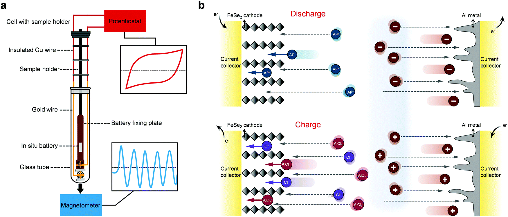 | ||
| Fig. 1 Schematics of in situ magnetometry technology and reaction mechanisms in an AIB. (a) Schematic of the advanced in situ magnetic testing setups. (b) Schematic illustration of the electrochemical process for the FeSe2 cathode in AIBs. | ||
Results and discussion
The synthetic process of FeSe2@GO is depicted in Fig. S1 (ESI†), and the more detailed synthesis strategy can be seen in Materials and Methods listed in the ESI.† The crystalline structures of the obtained FeSe2 and FeSe2@GO were characterized by X-ray diffraction (XRD). As shown in Fig. S2a and b (ESI†), all observed XRD peaks can be indexed to the orthorhombic FeSe2 (JCPDS card No. 79-1892) with no residues or impurity phase. Raman spectroscopic analyses were performed to confirm the formation of the composites (Fig. S3, ESI†).40 Typical disorder-induced D bands and the graphitic G bands of GO are clearly observed in the FeSe2@GO sample. The vibration modes of FeSe2 are also detected simultaneously from FeSe2@GO,41 suggesting that the GO has been successfully introduced into the composites. The morphology of the product was further identified with field-emission scanning electron microscopy (FESEM) and transmission electron microscopy (TEM). As shown in Fig. S4a (ESI†), a one-dimensional (1D) microrod morphology of the Fe2O3 precursor is revealed, and it consists of primary nanoparticles with a size of ∼100 nm in diameter (Fig. S5a, ESI†), forming a continuous porous structure. After converting into FeSe2, the overall microrod shape remains intact (Fig. S4b, ESI†). Interestingly, the size of the individual nanoparticles grows to ∼300 nm in diameter and an enlarged view is provided in Fig. S5b (ESI†). The morphology of the final product FeSe2@GO is displayed in Fig. S4c (ESI†), indicating that a thin layer of GO has been successfully coated on the surface of the rods, which can be further demonstrated by the TEM measurement shown in Fig. S6 (ESI†). From the high-resolution (HR) TEM image taken from the edge of the FeSe2@GO (Fig. S7a, ESI†), it can be clearly seen that FeSe2 is crystalline in nature with a lattice fringe spacing of 0.30 nm (Fig. S7b, ESI†), which can be indexed to the (011) crystal planes of FeSe2. Furthermore, the selected area electron diffraction (SAED) pattern for the FeSe2 region (Fig. S7c, ESI†) clearly proves the single-crystal nature of FeSe2@GO, matching well with its XRD pattern. Also Fig. S8 (ESI†) shows the energy-dispersive spectroscopy (EDS) elemental mapping of FeSe2@GO, revealing that C and O elements are distributed homogeneously on the surface of the rod-shaped FeSe2, which further confirms the introduction of GO.To evaluate the electrochemical performance of FeSe2@GO as the cathode of AIBs, cyclic voltammetry (CV) was carried out between 0.01 and 2.2 V (Fig. 2a), showing a dominant reduction peak at 1.84 V and an oxidation peak at 2.07 V, respectively. Galvanostatic charge–discharge curves in Fig. 2b show that the FeSe2@GO electrode operates along the expected plateau implied by the CV measurements, with a discharge specific capacity of up to 145 mAh g−1. Impressively, the present FeSe2@GO electrode exhibits not only high capacity but also high working potentials, indicating an overall high energy density output. Furthermore, the FeSe2@GO electrode can be effectively cycled at different current densities ranging from 1 A g−1 to as high as 10 A g−1, delivering reversible capacities of 145, 111, 100, 86, 78 and 75 mAh g−1, respectively (Fig. 2c). When the current density is switched abruptly from 10 to 1 A g−1 again, the discharge capacity can be recovered to its initial value without any sign of capacity loss. Fig. 2d presents the long-term cycling stability of FeSe2@GO at a current density of 1 A g−1, displaying a nearly constant specific capacity over 500 cycles with merely 0.06% capacity decay per cycle. In addition, the FeSe2@GO electrode is able to achieve Coulombic efficiency of over 98% after 500 cycles. As a comparison, the electrochemical performance of FeSe2 without the GO coating is shown in Fig. S9 (ESI†). Apparently, the bare FeSe2 exhibits inferior cycling life at 1 A g−1 and the specific capacity decreases rapidly to ∼21 mA h g−1 within 100 cycles. Fig. 2d also shows that the capacity contribution from GO to the overall capacity of the FeSe2@GO electrode is insignificant, but it is indispensable for the improved electrochemical performances in the composite electrode. In order to deepen the understanding of charge-transfer dynamics, the electrochemical impedance spectroscopy measurement and the equivalent circuit model were carried out as shown in Fig. S10 (ESI†). The charge transfer resistance (Rct) of the FeSe2@GO composite electrode is lower than that of the bare FeSe2 electrode, which indicates the excellent kinetics of the FeSe2@GO composite electrode,40,42 and thereby, leading to the superb electrochemical performances. We have also compared the performance parameter with state-of-the-art representatively reported congeneric AIBs such as G–VS2//Al,43 Cu2−xSe//Al,24 Co3S4//Al,31 G–SnS2//Al,5 MoS2/CNF//Al,44 CoS2@CNF//Al,45 CuS@C//Al,34 TiS2//Al,46 Ni3S2@Graphene//Al,6 VS4/rGO//Al,47 MoS2//Al,29 SnSe//Al48 and carbon paper//Al49 in Fig. 2e and Table S1 (ESI†). In general, in contrast to the low operating voltage and low specific capacity at moderate current densities observed in typical transition-metal composite based AIBs, FeSe2@GO exhibits the most outstanding electrochemical performances, which is possibly due to the advantage of the one-dimensional structure of the FeSe2@GO composite and the enhanced conductivity resulting from the introduction of GO.
 | ||
| Fig. 2 Electrochemical performance of the FeSe2-based cathode material. (a) CV curves at 0.5 mV s−1. (b) Typical charge and discharge curves at 1 A g−1. (c) Rate capability profiles. (d) Cycling stability over 500 cycles at 1 A g−1. (e) The comparison of operating voltage, capacity versus current densities of the FeSe2@GO electrode with various reported research electrodes for AIBs. | ||
It is of great interest to study the redox chemistry in the FeSe2-based AIB system, and detailed physicochemical property analyses were carried out on the rod-shaped FeSe2 electrode using a series of ex situ and in situ measurements during the cycling. The ex situ X-ray photoelectron spectroscopy (XPS) spectra of the FeSe2 electrode at different charge–discharge states are presented in Fig. 3a–d. To eliminate the effect of the trapped electrolyte and moisture, the electrodes were cleaned with propylene carbonate in a glovebox filled with argon, and then dried naturally. In the Fe 2p spectrum of the pristine FeSe2, two characteristic peaks located at 723.8 and 710.9 eV that correspond to the binding energies of Fe2+ 2p1/2 and Fe2+ 2p3/2 of FeSe2, together with two satellite peaks at 715.4 and 731.5 eV, respectively, are observed.50 Upon discharging to 0.01 V, two extra peaks (Fe 2p3/2 at 707.3 eV and Fe 2p1/2 at 720.5 eV) appear in the spectrum, which can be attributed to the reduction of Fe2+ to Fe0 due to the incorporation of Al3+ into the FeSe2 phase.23 However, these characteristic peaks of Fe0 still exist with the intensity decreased significantly after charging to 2.2 V, demonstrating that only part of the Fe0 can be oxidized reversibly. The Al 2p and Cl 2p spectra of the FeSe2 electrode were further collected, which are shown in Fig. 3b and c. It can be seen that the Al 2p XPS spectrum is remarkably more intense when fully discharged versus that in the fully charged state, which provides direct evidence of the incorporation of Al3+ during discharge. Note that the signal of Al 2p still exists in the FeSe2 electrode at the fully charged state, and it may be attributed to the following three points: (1) the Al3+ could not be completely extracted from the lattice of FeSe2, leading to the residual of AlxFeSe2; (2) contamination from the Al-containing electrolyte, due to the unsuccessful removal of the electrolyte; and (3) the AlCl4− anions may intercalate into the host and this phenomenon can also be found in other reported materials.51–53 Interestingly, the Cl 2p XPS spectrum of the FeSe2 electrode at the fully charged state shows a stronger signal than the discharge state, displaying an opposite trend compared with the Al 2p signal as shown in Fig. 3c. It is well known in the literature that free Cl−54–56 and AlCl4− anion clusters1,57 existing in the organic electrolyte tend to migrate to the cathode under the electric field during the charge process. Hence, it is quite possible that the significant increase of the Cl 2p signal after the charge process is caused by the intercalation of Cl− and AlCl4−. Fig. 3d shows the Se 3d XPS spectra of the pristine and fully discharged–charged FeSe2 electrodes. In the pristine state, the binding energy of Se 3d contains the 3d3/2 peak at ∼56.5 eV and the 3d5/2 peak at ∼54.7 eV. When the electrode has been fully discharged, the Se 3d signal is in accordance with the initial state. While in the fully charged state, a new peak appeared at 55.54 eV corresponding to the binding energy of Se0 3d, indicating the oxidation of Se.
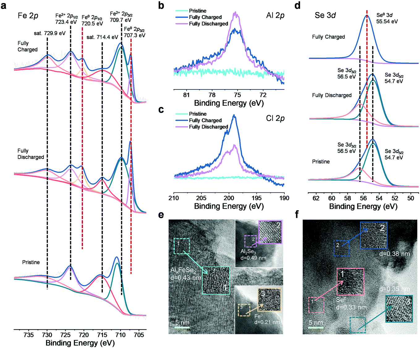 | ||
| Fig. 3 Valence states and atomistic evolution during cycling for the FeSe2 cathode material. (a–d) Ex situ XPS spectrum of the (a) Fe 2p, (b) Al 2p, (c) Cl 2p and (d) Se 3d peaks for pristine, fully charged and fully discharged FeSe2, respectively. (e) and (f) Ex situ TEM images of FeSe2 when discharged to 0.01 V and after charging back to 2.2 V. | ||
To further investigate the atomistic change of the FeSe2 cathode induced by the intercalation of different charge carriers, ex situ TEM measurements were performed. As shown in Fig. 3e and f, after being discharged to 0.01 V, well-resolved lattice fringes corresponding to Fe0 (0.21 nm) and Al2Se3 (0.49 nm) could be observed, resulting from the insertion of Al3+ into FeSe2. Notably, a few expanded lattice spacing (0.43 nm) compared with the structure of the predecessor can also be found in this region, corresponding to the discharging products AlxFeSe2,23,33,58 which indicates that the expected conversion reaction is not complete. The phenomenon of the incomplete redox reaction during cycling is also reported in other cathode materials for AIBs.23,31,45,53,58,59 After being fully charged back to 2.2 V, a lattice fringe of 0.33 nm can be observed and indexed to the (100) plane of Se. Two other expanded lattice fringes of 0.38 and 0.35 nm could also be observed. In association with the above-mentioned XPS results at the fully charged state, it can be reasonably assumed that they belong to (AlCl4)xFeSe2 and ClxFeSe2, respectively. These interesting structural evolutions strongly imply the possibility for intercalation of Cl− and AlCl4− into the FeSe2 host during the charge process.
Further investigations into the chemical structure and phase evolution of the FeSe2 cathode were carried out to support the above findings. Fig. 4a shows the in situ Raman spectra of the FeSe2 electrodes. In the initial discharge process, no notable change of Raman signals from the FeSe2 electrode could be detected. Nevertheless, in the reversible charge process, an extra peak located at ∼248 cm−1 appeared at ∼0.92 V and it survives until the end at a charge of 2.2 V. Such a peak belongs to FeCl2 resulting from the intercalation of Cl− due to which it matched well with that of the commercial FeCl2 as shown in Fig. S11 (ESI†). The ex situ XRD pattern collected at the fully charged state (2.2 V) (Fig. 4b) also shows the characteristic peaks of FeCl2, hence the intercalation of Cl− into FeSe2 during the charging process could be demonstrated. On the other hand, there is no success in detecting, by both the Raman and XRD studies, any evidence for the intercalation of AlCl4−. Instead, EDS mapping on the FeSe2 cathode at the fully charged state was conducted as shown in Fig. S12 (ESI†). The average atomic ratio of Cl and Al calculated from four different spots on the EDS mapping is found to be ∼5.30, which make the existence of two different charge carriers AlCl4− and Cl− during the charging process in FeSe2 based AIBs the most possible scenario.
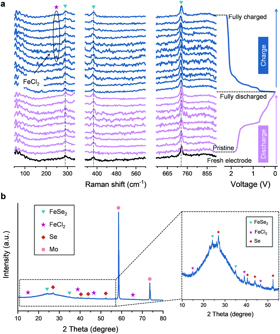 | ||
| Fig. 4 In situ Raman and ex situ XRD analysis of the FeSe2 cathode in an AIB. (a) In situ Raman spectra of the FeSe2 cathode recorded during charging and discharging processes. The peaks are marked with purple pentagrams, blue triangles correspond to FeCl2 and FeSe2, respectively. (b) Ex situ XRD spectra of the FeSe2-based electrode at the fully charged state. The peaks are marked with brown rhombus, and pink circles correspond to Se and Mo, respectively, Mo comes from current collector. | ||
Because the magnetic properties are sensitive to phase composition, structural transformation and the transfer of electrons (whether on the surface of the material or in the bulk) in transition metals and their compounds,60–63 the aluminium storage mechanism of the FeSe2 cathode is further explored by means of magnetic characterization. The ex situ magnetic hysteresis loops were firstly acquired as displayed in Fig. 5a. A significant increase in magnetization can be observed for FeSe2 in its fully discharged state, implicating the formation of Fe0 particles resulting from the reduction of FeSe2. Upon charging back to 2.2 V, the magnetization shows a pronounced decrease, but not to the value at the initial state, indicating that the redox reaction is not highly reversible. These results are in agreement with the ex situ XPS and TEM analysis. Next, the magnetic responses accompanying the discharge–charge processes were monitored using in situ magnetometry in real time. As shown in Fig. 5b, the magnetization keeps rising up to ∼3.7 emu g−1 during discharging (electrochemical reduction) when the potential decreases to ∼0.05 V, which could be interpreted as the formation of Fe0. It should be pointed out that, when the potential continued to decrease down to 0.01 V, the magnetization is nearly unchanged. However, the magnetization continues to increase to ∼3.9 emu g−1 in the subsequent charge (electrochemical oxidation) process, and the maximum value remained at 0.69 V. Such an abnormal magnetic change during both the discharge–charge processes at low voltage is reminiscent of our proposed spin-polarized surface capacitance behavior.38,39 Specifically, spin-polarized electrons are injected into the reduced transition metal nanoparticles (formed by the conversion reactions in the discharge process) to a depth on the order of the Thomas–Fermi screening length, while the cations are stored at the grain boundaries and surfaces, forming a space charge zone, which can produce a notable change in the interface magnetization.
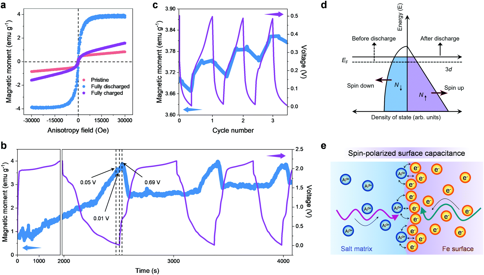 | ||
| Fig. 5 Magnetic characterization of the FeSe2 cathode. (a) Magnetic hysteresis loops of the as-prepared FeSe2 cathode for pristine, fully charged and fully discharged states. (b) The electrochemical charge–discharge profiles of FeSe2 and the corresponding reversible in situ magnetic response at an applied magnetic field of 3 T. (c) The corresponding operando magnetic responses over the potential range of 0.01–0.5 V. (d) The spin-polarized density of states at the surface of ferromagnetic metal grains. (e) Formation of a space charge zone in the surface capacitance model for extra aluminium storage. | ||
To further corroborate these findings, the magnetization variation of the FeSe2//Al battery upon cycling at low voltage (to exclude the effect of redox) was measured (Fig. 5c, the FeSe2//Al battery was discharged to 0.01 V in advance before testing). It can be observed that, being slightly different from that shown in Fig. 5b, the magnetization decreases significantly during the discharge process. It should be borne in mind that the fine Fe0 nanoparticles with a high density of states (DOS) at the Fermi level owing to the highly localized d orbitals can be created during the discharge (Fig. 3e), and the surface DOS of Fe shows that the spin-up d bands are filled much more than the spin-down d bands (Fig. 5d). Hence, it is reasonable to conjecture that electrons stored in the spin-split bands of the Fe0 nanoparticles can trigger a monotonic magnetization reduction during the discharge, which is in perfect agreement with the experimental results mentioned above. Fig. 5e schematically illustrates the formation of a space charge zone in the spin-polarized surface capacitance towards Al3+ storage, where spin-polarized electrons are injected into the DOS of Fe while Al3+ ions are stored outside the particles at the grain boundaries and surfaces. For the reversible charge process, the magnetization increases anew with the release of the spin-polarized electrons, which is opposite to that in the discharge process, further demonstrating that the spin-polarized surface capacitance dominates this cycling voltage range (0.01–0.5 V) in the FeSe2//Al battery.
In the end, to confirm the feasibility of hosting multiple charge carriers inside the FeSe2 material, first-principles calculations based on density functional theory (DFT) were performed. The calculations were carried out based on a periodic 2 × 2 × 1 supercell, which can avoid the interaction between adsorbate ions and its images in the neighboring supercells. For studying the insertion of ions within the FeSe2 lattice, a site with high binding energy had been selected when considering the orthorhombic symmetry (Fig. 6), which displays a possibly stable insertion configuration.64 For the configuration, the formation energy (Eb) of the intercalated ions is defined as: Eb = E(Total) − E(FeSe2) − E(AlxCly), where E(Total), E(FeSe2) and E(AlxCly) are the total energies of the FeSe2 supercell with/without inserted ions, and ions in the reservoir, respectively.
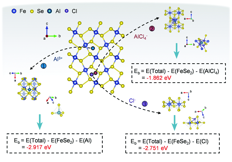 | ||
| Fig. 6 DFT calculations of the FeSe2 AIB. The formation energy of Al3+, Cl− and AlCl4− within the lattices of FeSe2. | ||
The intercalation of ions into the FeSe2 cathode was assessed by calculating the formation energy of ions, where a lower value implies a more facile ion embedding process, while a negative value implies stable insertion of ions. As shown in Fig. 6 and Table S2 (ESI†), the formation energies of Al3+, Cl−, and AlCl4− at the inferred adsorption sites are −2.917, −2.751 and −1.862 eV, respectively, suggesting that the insertion reactions of these ions are all feasible.35 Therefore, the DFT results are consistent with the above experimental observations and give strong theoretical evidence for the aluminium storage mechanism in the FeSe2 electrode.
On the basis of the above characterization and analyses, the aluminium storage mechanism of FeSe2 which undergoes multistep reactions involving three different charge carriers, Cl−, AlCl4− and Al3+, at the voltage range of 0.01–2.2 V (vs. Al3+/Al) is formulated as follows
For the cathode side:
Discharge process:
| [AlCl4−]nFeSe2 + [Cl−]m−2FeSe2 + FeCl2 + 2Se + (m + n)e− → 3FeSe2 + n[AlCl4−] + m[Cl−] (after the first charge) | (1) |
| FeSe2 + x[Al3+] + 3xe− → AlxFeSe2 | (2) |
| AlxFeSe2 → AlxSe2 + Fe | (3) |
 | (4) |
 | (5) |
| Fe + AlxSe2 → AlxFeSe2 | (6) |
| AlxFeSe2 → FeSe2 + x[Al3+] + 3xe− | (7) |
| 3FeSe2 + m[Cl−] + n[AlCl4−] → [AlCl4−]nFeSe2 + [Cl−](m−2)FeSe2 + FeCl2 + 2Se + (m + n)e− | (8) |
For the anode side:
| Al3+ + 7[AlCl4−] ↔ 4[Al2Cl7−] | (9) |
The typical cathode reactions in the discharge process are expressed by eqn (1), (2), (3) and (4), where x, m, and n represent the ratio of the Al3+ cation, Cl− and AlCl4− anions to FeSe2, respectively, and y represents the ratio of spin-polarized electrons to Fe. Here we should bear in mind that, first, the expected redox reaction in eqn (3) is not complete and only partially reversible. second, AlxSe2 could play the role of a medium for storing extra Al3+ in eqn (4), similar to Li2O in the previously reported Li-based system.38Eqn (5), (6), (7) and (8) propose the reactions during the charging process, and the typical aluminium deposition and shedding reactions are exhibited in eqn (9). Apparently, both the internal environment and reaction mechanisms of FeSe2 AIBs are very complicated, and more detailed characterization will be needed to completely understand the whole electrochemical cycles. Nevertheless, three different charge carriers including Cl−, AlCl4− and Al3+ can be ascertained to exist during the charge–discharge processes, as is evident from the combined experimental and theoretical approach carried out in this work.
Conclusions
In summary, an FeSe2-based cathode with high capacity and high operating potential was developed facilely, which can enable a fast rate capability and durable cyclability with a high Coulombic efficiency of over 98%. Most importantly, the aluminium storage mechanisms in FeSe2 are systematically investigated by a series of techniques. The results reveal that the electrochemical charge–discharge process proceeds by multistep reactions involving three different charge carriers, Cl−, AlCl4− and Al3+, among which the former two works during the charging process while the last one participated in the reaction in the discharging process. Furthermore, in situ magnetometry demonstrates the existence of spin-polarized surface capacitance in AIBs for the first time, proving that Al3+ can be used as a charge compensator in the formation of space charge zones with electrons. The understanding of these new aluminium storage mechanisms opens the door for rethinking of the key rules of the design and preparation of electrode materials with high electrochemical performance to obtain significant improvement.Author contributions
H. L. conceived and designed the experiments. H. W., L. Z., H. Z., Y. L., L. Y., F. L., W. L. and X. D. carried out the synthesis and electrochemical test. H. W., Y. X., Y. W. and K. W. performed the in situ Raman test. X. Q. and L. W. performed the ex situ XRD test. Q. L., H. L., X. L. and Z. L. carried out in situ magnetism measurement. S. Y. assisted in the interpretation of the magnetization variation. H. L., F. L., H. Y., Q. L., X. Z. and H. W. analyzed the data and co-wrote the paper. All authors discussed the experiments and final manuscript.Conflicts of interest
There are no conflicts to declare.Acknowledgements
H. L. acknowledges the support from the National Natural Science Foundation of China (51804173 and 11504192), and the National Natural Science Foundation of Shandong Province (ZR2018BB030).References
- M. C. Lin, M. Gong, B. Lu, Y. Wu, D. Y. Wang, M. Guan, M. Angell, C. Chen, J. Yang, B. J. Hwang and H. Dai, Nature, 2015, 520, 325–328 CrossRef PubMed.
- H. Chen, H. Xu, S. Wang, T. Huang, J. Xi, S. Cai, F. Guo, Z. Xu, W. Gao and C. Gao, Sci. Adv., 2017, 3, eaao7233 CrossRef.
- D.-Y. Wang, C.-Y. Wei, M.-C. Lin, C.-J. Pan, H.-L. Chou, H.-A. Chen, M. Gong, Y. Wu, C. Yuan, M. Angell, Y.-J. Hsieh, Y.-H. Chen, C.-Y. Wen, C.-W. Chen, B.-J. Hwang, C.-C. Chen and H. Dai, Nat. Commun., 2017, 8, 14283 CrossRef CAS.
- Z. Lin, M. Mao, C. Yang, Y. Tong, Q. Li, J. Yue, G. Yang, Q. Zhang, L. Hong, X. Yu, L. Gu, Y.-S. Hu, H. Li, X. Huang, L. Suo and L. Chen, Sci. Adv., 2021, 7, eabg6314 CrossRef CAS PubMed.
- Y. Hu, B. Luo, D. Ye, X. Zhu, M. Lyu and L. Wang, Adv. Mater., 2017, 29, 1606132 CrossRef.
- S. Wang, Z. Yu, J. Tu, J. Wang, D. Tian, Y. Liu and S. Jiao, Adv. Energy Mater., 2016, 6, 1600137 CrossRef.
- Z. Zhao, Z. Hu, Q. Li, H. Li, X. Zhang, Y. Zhuang, F. Wang and G. Yu, Nano Today, 2020, 32, 100870 CrossRef CAS.
- D. J. Kim, D.-J. Yoo, M. T. Otley, A. Prokofjevs, C. Pezzato, M. Owczarek, S. J. Lee, J. W. Choi and J. F. Stoddart, Nat. Energy, 2018, 4, 51–59 CrossRef.
- J. Zheng, D. C. Bock, T. Tang, Q. Zhao, J. Yin, K. R. Tallman, G. Wheeler, X. Liu, Y. Deng, S. Jin, A. C. Marschilok, E. S. Takeuchi, K. J. Takeuchi and L. A. Archer, Nat. Energy, 2021, 6, 398–406 CrossRef CAS.
- Z. Zhao, Z. Hu, R. Jiao, Z. Tang, P. Dong, Y. Li, S. Li and H. Li, Energy Storage Mater., 2019, 22, 228–234 CrossRef.
- H. Yang, H. Li, J. Li, Z. Sun, K. He, H.-M. Cheng and F. Li, Angew. Chem., Int. Ed., 2019, 58, 11978–11996 CrossRef CAS.
- S. He, J. Wang, X. Zhang, J. Chen, Z. Wang, T. Yang, Z. Liu, Y. Liang, B. Wang, S. Liu, L. Zhang, J. Huang, J. Huang, L. A. O'Dell and H. Yu, Adv. Funct. Mater., 2019, 29, 1905228 CrossRef CAS.
- D.-J. Yoo, M. Heeney, F. Glöcklhofer and J. W. Choi, Nat. Commun., 2021, 12, 2386 CrossRef CAS.
- Z. Hu, H. Zhang, H. Wang, F. Zhang, Q. Li and H. Li, ACS Mater. Lett., 2020, 2, 887–904 CrossRef CAS.
- C. Yan, C. Lv, L. Wang, W. Cui, L. Zhang, K. N. Dinh, H. Tan, C. Wu, T. Wu, Y. Ren, J. Chen, Z. Liu, M. Srinivasan, X. Rui, Q. Yan and G. Yu, J. Am. Chem. Soc., 2020, 142, 15295–15304 CrossRef CAS.
- Z. Liu, J. Wang, H. Ding, S. Chen, X. Yu and B. Lu, ACS Nano, 2018, 12, 8456–8466 CrossRef CAS PubMed.
- X. Yu, B. Wang, D. Gong, Z. Xu and B. Lu, Adv. Mater., 2017, 29, 1604118 CrossRef.
- C. Li, S. Dong, R. Tang, X. Ge, Z. Zhang, C. Wang, Y. Lu and L. Yin, Energy Environ. Sci., 2018, 11, 3201–3211 RSC.
- Y. Kong, C. Tang, X. Huang, A. K. Nanjundan, J. Zou, A. Du and C. Yu, Adv. Funct. Mater., 2021, 31, 2010569 CrossRef CAS.
- Y. Chen, Z. Wang, X. Li, X. Yao, C. Wang, Y. Li, W. Xue, D. Yu, S. Y. Kim, F. Yang, A. Kushima, G. Zhang, H. Huang, N. Wu, Y. W. Mai, J. B. Goodenough and J. Li, Nature, 2020, 578, 251–255 CrossRef PubMed.
- H. Huang, F. Zhou, X. Shi, J. Qin, Z. Zhang, X. Bao and Z.-S. Wu, Energy Storage Mater., 2019, 23, 664–669 CrossRef.
- P. Wang, H. Chen, N. Li, X. Zhang, S. Jiao, W.-L. Song and D. Fang, Energy Storage Mater., 2018, 13, 103–111 CrossRef.
- T. Cai, L. Zhao, H. Hu, T. Li, X. Li, S. Guo, Y. Li, Q. Xue, W. Xing, Z. Yan and L. Wang, Energy Environ. Sci., 2018, 11, 2341–2347 RSC.
- J. Jiang, H. Li, T. Fu, B. J. Hwang, X. Li and J. Zhao, ACS Appl. Mater. Interfaces, 2018, 10, 17942–17949 CrossRef PubMed.
- W. Guan, L. Wang, H. Lei, J. Tu and S. Jiao, Nanoscale, 2019, 11, 16437–16444 RSC.
- Y. Du, S. Zhao, C. Xu, W. Zhang, S. Fan, P. Li, H. Jin, Y. Zhang and J. Zhang, ChemElectroChem, 2019, 6, 4437–4443 CrossRef.
- W. Xing, D. Du, T. Cai, X. Li, J. Zhou, Y. Chai, Q. Xue and Z. Yan, J. Power Sources, 2018, 401, 6–12 CrossRef.
- L. Geng, G. Lv, X. Xing and J. Guo, Chem. Mater., 2015, 27, 4926–4929 CrossRef.
- Z. Li, B. Niu, J. Liu, J. Li and F. Kang, ACS Appl. Mater. Interfaces, 2018, 10, 9451–9459 CrossRef PubMed.
- Y. Hu, D. Ye, B. Luo, H. Hu, X. Zhu, S. Wang, L. Li, S. Peng and L. Wang, Adv. Mater., 2018, 30, 1703824 CrossRef PubMed.
- H. Li, H. Yang, Z. Sun, Y. Shi, H.-M. Cheng and F. Li, Nano Energy, 2019, 56, 100–108 CrossRef.
- K. Liang, L. Ju, S. Koul, A. Kushima and Y. Yang, Adv. Energy Mater., 2019, 9, 1802543 CrossRef.
- H. Hong, J. Liu, H. Huang, C. Atangana Etogo, X. Yang, B. Guan and L. Zhang, J. Am. Chem. Soc., 2019, 141, 14764–14771 CrossRef PubMed.
- S. Wang, S. Jiao, J. Wang, H.-S. Chen, D. Tian, H. Lei and D.-N. Fang, ACS Nano, 2017, 11, 469–477 CrossRef PubMed.
- W. Wang, B. Jiang, W. Xiong, H. Sun, Z. Lin, L. Hu, J. Tu, J. Hou, H. Zhu and S. Jiao, Sci. Rep., 2013, 3, 3383 CrossRef PubMed.
- Z. Zhao, Z. Hu, H. Liang, S. Li, H. Wang, F. Gao, X. Sang and H. Li, ACS Appl. Mater. Interfaces, 2019, 11, 44333–44341 CrossRef CAS.
- Z. Li, Y. Zhang, X. Li, F. Gu, L. Zhang, H. Liu, Q. Xia, Q. Li, W. Ye, C. Ge, H. Li, H. Hu, S. Li, Y. Z. Long, S. Yan, G. X. Miao and Q. Li, J. Am. Chem. Soc., 2021, 143, 12800–12808 CrossRef CAS.
- Q. Li, H. Li, Q. Xia, Z. Hu, Y. Zhu, S. Yan, C. Ge, Q. Zhang, X. Wang, X. Shang, S. Fan, Y. Long, L. Gu, G. X. Miao, G. Yu and J. S. Moodera, Nat. Mater., 2021, 20, 76–83 CrossRef CAS PubMed.
- H. Li, Z. Hu, Q. Xia, H. Zhang, Z. Li, H. Wang, X. Li, F. Zuo, F. Zhang, X. Wang, W. Ye, Q. Li, Y. Long, Q. Li, S. Yan, X. Liu, X. Zhang, G. Yu and G. X. Miao, Adv. Mater., 2021, 33, e2006629 CrossRef PubMed.
- S. Zhou, P. Huang, T. Xiong, F. Yang, H. Yang, Y. Huang, D. Li, J. Deng and M. J. T. Balogun, Small, 2021, 17, e2100778 CrossRef PubMed.
- Y. Tang, Z. Zhao, X. Hao, Y. Wei, H. Zhang, Y. Dong, Y. Wang, X. Pan, Y. Hou, X. Wang and J. Qiu, J. Mater. Chem. A, 2019, 7, 4469–4479 RSC.
- Y. Huang, H. Yang, T. Xiong, D. Adekoya, W. Qiu, Z. Wang, S. Zhang and M. S. Balogun, Energy Storage Mater., 2020, 25, 41–51 CrossRef.
- L. Wu, R. Sun, F. Xiong, C. Pei, K. Han, C. Peng, Y. Fan, W. Yang, Q. An and L. Mai, Phys. Chem. Chem. Phys., 2018, 20, 22563–22568 RSC.
- W. Yang, H. Lu, Y. Cao, B. Xu, Y. Deng and W. Cai, ACS Sustainable Chem. Eng., 2019, 7, 4861–4867 CrossRef.
- R. Zhuang, Z. Huang, S. Wang, J. Qiao, J.-C. Wu and J. Yang, Chem. Eng. J., 2021, 409, 128235 CrossRef CAS.
- L. Geng, J. P. Scheifers, C. Fu, J. Zhang, B. P. T. Fokwa and J. Guo, ACS Appl. Mater. Interfaces, 2017, 9, 21251–21257 CrossRef PubMed.
- X. Zhang, S. Wang, J. Tu, G. Zhang, S. Li, D. Tian and S. Jiao, ChemSusChem, 2018, 11, 709–715 CrossRef PubMed.
- Y. Zhang, B. Zhang, J. Li, J. Liu, X. Huo and F. Kang, Chem. Eng. J., 2021, 403, 126377 CrossRef.
- H. Sun, W. Wang, Z. Yu, Y. Yuan, S. Wang and S. Jiao, Chem. Commun., 2015, 51, 11892–11895 RSC.
- W. Ye, K. Wang, W. Yin, W. Chai, B. Tang and Y. Rui, Electrochim. Acta, 2019, 323, 134817 CrossRef.
- H. D. Yoo, Y. Liang, H. Dong, J. Lin, H. Wang, Y. Liu, L. Ma, T. Wu, Y. Li, Q. Ru, Y. Jing, Q. An, W. Zhou, J. Guo, J. Lu, S. T. Pantelides, X. Qian and Y. Yao, Nat. Commun., 2017, 8, 339 CrossRef PubMed.
- J. K. Kim, G. D. Park, J. H. Kim, S.-K. Park and Y. C. Kang, Small, 2017, 13, 1700068 CrossRef.
- Y. Ai, S.-C. Wu, K. Wang, T.-Y. Yang, M. Liu, H.-J. Liao, J. Sun, J.-H. Chen, S.-Y. Tang, D. C. Wu, T.-Y. Su, Y.-C. Wang, H.-C. Chen, S. Zhang, W.-W. Liu, Y.-Z. Chen, L. Lee, J.-H. He, Z. M. Wang and Y.-L. Chueh, ACS Nano, 2020, 14, 8539–8550 CrossRef CAS PubMed.
- X. Shen, T. Sun, L. Yang, A. Krasnoslobodtsev, R. Sabirianov, M. Sealy, W. N. Mei, Z. Wu and L. Tan, Nat. Commun., 2021, 12, 820 CrossRef CAS.
- C. Ferrara, V. Dall’Asta, V. Berbenni, E. Quartarone and P. Mustarelli, J. Phys. Chem. C, 2017, 121, 26607–26614 CrossRef CAS.
- H. Xu, T. Bai, H. Chen, F. Guo, J. Xi, T. Huang, S. Cai, X. Chu, J. Ling, W. Gao, Z. Xu and C. Gao, Energy Storage Mater., 2019, 17, 38–45 CrossRef.
- N. S. Hudak, J. Phys. Chem. C, 2014, 118, 5203–5215 CrossRef CAS.
- L. Xing, K. A. Owusu, X. Liu, J. Meng, K. Wang, Q. An and L. Mai, Nano Energy, 2021, 79, 105384 CrossRef CAS.
- Y. Tong, A. Gao, Q. Zhang, T. Gao, J. Yue, F. Meng, Y. Gong, S. Xi, Z. Lin, M. Mao, S. Peng, X. Wang, D. Xiao, D. Su, Y. Luo, H. Li, L. Chen, L. Suo and L. Gu, Energy Storage Mater., 2021, 37, 87–93 CrossRef.
- S. Dasgupta, B. Das, M. Knapp, R. A. Brand, H. Ehrenberg, R. Kruk and H. Hahn, Adv. Mater., 2014, 26, 4639–4644 CrossRef CAS.
- M. Weisheit, S. Fähler, A. Marty, Y. Souche, C. Poinsignon and D. Givord, Science, 2007, 315, 349–351 CrossRef CAS PubMed.
- G. Gershinsky, E. Bar, L. Monconduit and D. Zitoun, Energy Environ. Sci., 2014, 7, 2012–2016 RSC.
- T. Yamada, K. Morita, H. Wang, K. Kume, H. Yoshikawa and K. Awaga, Angew. Chem., Int. Ed., 2013, 52, 6238–6241 CrossRef CAS.
- B. Delley, J. Chem. Phys., 2000, 113, 7756–7764 CrossRef.
Footnotes |
| † Electronic supplementary information (ESI) available: Experimental methods, phase characterization, mapping patterns and Raman spectroscopy. See DOI: 10.1039/d1ee03070a |
| ‡ H. W. and L. Z. contributed equally to this work. |
| This journal is © The Royal Society of Chemistry 2022 |