 Open Access Article
Creative Commons Attribution 3.0 Unported Licence
Process intensification of element extraction using centrifugal contactors in the nuclear fuel cycle†
Alastair
Baker
 *a,
Alex
Fells
 a,
Michael J.
Carrott
b,
Chris J.
Maher
b and
Bruce C.
Hanson
 a
a
aSchool of Chemical and Process Engineering, University of Leeds, Leeds, UK. E-mail: A.R.Baker@leeds.ac.uk
bUK National Nuclear Laboratory, Seascale, UK
First published on 27th April 2022
Abstract
This review focuses on consolidating solvent extraction performed in the process intensification equipment known as Centrifugal Contactors (CCs), implemented in Spent Nuclear Fuel (SNF) reprocessing and radioactive waste processing. Recovery of valuable actinides is important from sustainability perspectives as it is a source of metals of technological interest from SNF, specifically the recovery of fissile and fertile material, and can also be employed in the processing of Waste Electrical and Electronic Equipment (WEEE). Solvent extraction (also referred to as liquid–liquid extraction, or aqueous separation), is employed in the separation of f-block elements and fission products in SNF. The sequential isolation using different flowsheets has been performed on a range of scales using CCs. However, solids, either present in the feed solution or formed in situ, are always cited as a concern for the operability of CCs, and their extraction efficiencies. This review quantifies the unexpected solid arisings and accumulation during operation in the presence and absence of highly radioactive isotopes from bench to plant scale. The review concludes with techniques implemented for the removal of solids from CCs.
Nuclear fuel cycle
At the atomic level, all elements are reusable, i.e. they can be recycled indefinitely. Recycling desirable elements from compounds requires chemically dissolving compounds in a medium, such as acids, then separating them into their constituents. However, as there is ever-growing global demand and a comprehensive understanding that resources are finite, closed-cycle systems for the scarce and endangered elements must be implemented to avoid losing them. This drives the pursuit to supersede the open cycle and develop a circular economy,1 where waste is eliminated, materials are recycled and recirculated, and both resources and the environment are protected. In the nuclear sector, separation of elements from irradiated fuel has always been fundamental. However, with the initial purpose of recovering plutonium for nuclear weapons, but concurrently the civil nuclear industry has driven the development of recycle technology, creating a circular economy for the sustainable use of f-block elements for civilian power generation.2At present, most nuclear nations pursue an unsustainable open cycle, where the disposal of spent nuclear fuel without separation in deep geological disposal facilities is the norm.3 If this situation continues, current estimates of virgin uranium sources are estimated to last 80 years.3 The consumption, or ‘burning,’ of virgin nuclear fuel is the conversion of fissile isotopes into fission products, neutrons and electromagnetic radiation, occurring at the atomic level traditionally in pure uranium oxide pellets. Fuel is defined as “spent,” (or more appropriately as “used”), once a portion of the fissile isotopes are consumed, resulting in the build-up of fission products, impeding further fission reactions and energy generation. Chemically, spent nuclear fuel does not differ significantly from virgin fuel, as only a small proportion of the uranium is converted (equating to the fissile content), so the composition of spent fuel (typically) consists of 96% the original uranium, with the 4% consisting of mixed fissile and fertile higher actinides, lanthanides and fission products. The chemical composition will further vary after every successful open cycle burnup as heavier transuranics become more prevalent.
Recycling these materials provides access to a closed fuel cycle which has many advantages.4,5 One advantage will be a reduction in the size of Geological Disposal Facilities (GDFs), as a result of reduced decay time, reduced heat loadings to the GDFs, reduced radiotoxicity and reduced size through consumption of fertile material whilst maintaining fissile content in fourth-generation fast reactors.3 Numerous commercial-scale facilities have been built worldwide to recycle spent nuclear fuel, primarily based on the Plutonium Uranium Reduction EXtraction (PUREX) process that uses solvent extraction to separate U and Pu from unwanted fission products.6 Future developments have looked to extend the range of species recovered to include Np, Am, and Cm to increase the fuel cycle's sustainability. Furthermore, ‘bolt-on’ flowsheets have been designed to treat the PUREX raffinate/waste generated to further reduce the decay time and heat loading, for example, using the Selective ActiNide EXtraction (SANEX) process to extract An3+.3 As these new processes are developing, there is a parallel development of solvent extraction technology to intensify the process and drive down costs. A series of partitioning approaches have been demonstrated in centrifugal contactors (CC) to intensify the process.7
The wide range of elements present in spent nuclear fuel and the flowsheet chemistry can result in unexpected side products. Furthermore, implementing these chemical reactions at different scales and intensities can further deviate from the expected behaviour. Of particular concern is the presence of solids, either formed in situ or entrained, as these tend to adhere to CC walls due to centrifugal force, resulting in reduced extraction efficiency.
Aims and objectives
Due to the extensive application of centrifugal contactors, this review aims to consolidate flowsheet chemistries and substrates demonstrated in a laboratory setting and implemented industrially within the nuclear fuel cycle. The review focuses on the formation of precipitates and third phases. The resultant effect of unpredicted precipitation upon solvent extraction, including entrainment and hydrodynamic failure, will also be considered. The review will conclude with a summary of solids generated, chemical solutions developed to prevent precipitation and mitigation strategies.Centrifugal contactors
CCs, also known as the centrifugal extractor, annular centrifugal extractor (ACE) and annular centrifugal contactor (ACC), are process intensification equipment for solvent extraction that contact an immiscible ligand with aqueous metals utilising high shear mixing to form a dispersion of droplets with a high surface to volume ratio, facilitating high rates of mass transfer. The two immiscible liquid phases are then separated using centrifugal force.Current technologies, such as mixer settlers and pulsed columns, rely on gravity. Replacing gravity with centrifugal force drastically reduces the time required for emulsion/dispersed phases to separate and reduces the area over which these solutions need to settle. The high-speed rotation also provides highly efficient shear mixing in a shorter footprint than a PC. There are excellent reviews on centrifugal contactors design principles9 and implementation in nuclear research.10 CCs as continuous counter-current extractors, like the forgoing mixer-settlers and pulsed-columns, perform sequential stage wise extraction and back extraction, more recently termed as continuous telescoped reactions. However, changes in concentration and polarity of solvents in a cascade of reaction may result in solids precipitation in a process designed for liquid phases only.
A CC consists of two cylinders, the outer cylinder is stationary, and the inner hollow cylinder containing vanes rotates (Fig. 1). The space between the two cylinders produces an annulus mixing region. Typically two immiscible liquids of different densities are pumped into an annular mixing zone, which is the void between a stationary outer and an inner rotating cylinder. The rotation creates a high shear mixing zone within the annulus and breaks up the two phases into a fine dispersion. The hydrodynamic principle used is that the inner cylinder rotation is above a threshold that destabilises Couette flow regimes and provides sufficient shear to induce Taylor vortexes through turbulent flows. The internal cylinder rotation also provides a vertical pumping motion, forcing the fluids downwards, where they are drawn up into the hollow inner rotating cylinder using guide vanes. The centrifugal force within the inner rotating cylinder then separates the two phases. Four flow regimes, which are covered in great depth by Vedantam and Joshi,11 have been defined for this type of CC.
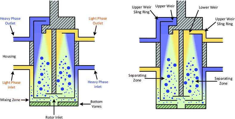 | ||
| Fig. 1 Diagram of CC, left showing the housing labelled in which sheer mixing occurs, right showing the inner hollow rotor in which phase separation follows.8 | ||
Around the world, several organisations have pursued the development of CCs. Webster and co-workers initially developed the design of centrifugal contactors at the Savannah River Plant with a paddle mixer below the rotor12 specifically for spent nuclear fuel (SNF) reprocessing, then Bernstein and co-workers at Argonne National Lab (ANL) replaced the paddle with fixed baffles at the base of the annular mixing zone.13–16 ‘Leonard and co-workers, also at ANL, developed many practical concepts and improved upon the design and utility of [CCs].16’
The commercialisation of the ANL design was carried out in partnership between AINL and Costner Industries Nevada Corporation (CINC) via a technical transfer agreement, for CCs to be used in other solvent extraction processes outside of the nuclear sector requiring process intensification.
The Institute of Nuclear and New Energy Technology (INET), Tsinghua University, developed an annular centrifugal contactor design.17 These centrifugal contactors have been used at the UK's National Nuclear Laboratory (formerly British Nuclear Fuels Limited, BNFL)18,19 and Germany's Institute of Energy and Climate Research.20
The French Atomic Energy Commission (Commissariat à l’Énergie Atomique or CEA) also developed a centrifugal contactor that appeared to be the basis for the Rousselet Robatel (RR) centrifugal contactor.21,22 The CEA also developed a novel design referred to as the ECRAN (the initials of the French words for centrifugal extractor with filled agitated rotor) for liquid–liquid systems that are sensitive to shearing, which can be encountered when washing solvents.23 The Japan Atomic Energy Agency (JAEA)24 and India's Indira Gandhi Center for Atomic Research25 have also deployed independent designs of contactors of different diameters. Connecting several stages produces a cascade in which several sequences of chemical reactions can be performed using a continuous stream of aqueous feed.
‘Commercially available contactors are now sold, with significant numbers of units being utilized in a wide range of separations, both in industrial and government sectors.26,27’ CCs are routinely used to develop the flowsheets for solvent extraction processes and radioactive waste treatment in France, Russia, China, USA and Japan. This is due to the advantages of performing experiments in CCs; small quantities are needed that generate less waste and reduce residence times, leading to flowsheets achieving steady-state in a shorter time.
This intensification processing technology includes; ‘lowering in-process volume [and] residence time, per stage, rapid mixing and separation in a single unit, connection-in-series for multi-stage use, and a wide operating range of input flow rates and phase ratios without adjustments. The centrifugal contactor is the equipment of choice for new solvent extraction based separations of SNF, primarily due to the minimisation of radiation exposure to the solvents.’26
However, ‘evaluation of these commercial units in support of the various nuclear fuel cycle and radioactive waste management goals is […] ongoing.’16 ‘Advantages of the centrifugal equipment over the pump-mix mixer-settler are associated principally with the fiftyfold reduction in liquid volume holdup and include reduced exposure of the solvent to radiolytic degradation, increase nuclear safety, easier flushing, and greater operating flexibility.28’
Partitioning and extraction of spent nuclear fuel f-block elements
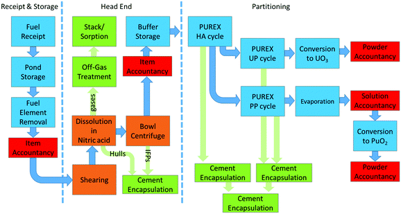
In the nuclear fuel cycle, the recovery of f-block elements is performed on a commercial scale and is known as reprocessing. At present, all commercial reprocessing plants employ aqueous recycling. There are several steps, specifically three key processes; receipt and storage, head-end processing and ultimately partitioning. Fig. 2 shows the expanded steps under each of these processes, using the UK's Thermal Oxide Reprocessing Plant, also known as THORP, as an example. Of relevance to f-element extraction, after initial storage allowing cooling SNF, the SNF is dissolved in nitric acid (in concentrations up to 7 M) after the cladding has been sheared to expose the fuel. The remaining pieces of cladding that are not dissolved are sent for cement encapsulation before it is sent to the GDF. Further solid management is required, and the solution from the dissolver is then clarified by settling and centrifugation to remove undissolved particulate solids (noble metals and metal oxides).However, small undissolved particles may not be separated and remain in suspension and may enter the aqueous reprocessing feed tank. This is an important fact that must be considered when undertaking process intensification within SNF processing due to criticality concerns. The aqueous feed containing the dissolved SNF is then treated sequentially with discrete compositions of selective ligands to partition and separate elements.
A concern in implementing CCs in nuclear reprocessing applications is a mechanical failure or a potential blockage. Operating CCs with feeds containing suspended particulates will result in particulate capture in the rotor assembly by high centrifugal forces leading to the formation of a cake/bed on the spinning rotor's inner wall. The cakes may negatively affect phase separations and introduce balance problems within the high speed inner rotating cylinder.
Solids in spent nuclear fuel aqueous phase to a solvent extraction process exist either as; fines that escape the filtration (typically using a bowl centrifuge) and are carried over from the dissolver, insoluble reaction products designated as “interface crud” or are generated in situ due to aggregation of nanoparticles and precipitation or the generation of solids via the degradation of solvent and ligand. Long duration exposure to high energy radiation through extended flowsheet operations is often cited as a potential problem that needs to be identified, both concerning ‘solvent degradation or long term buildup of materials in the organic phases.29’
The settling of solids under gravitational force, or G-force, measured as 1 G, is one of the most significant concerns when considering CC implementation for solvent extraction process intensification.30 The greater G-force in a CC (compared to gravity settling systems) results in solids accumulating as a bed along the rotor cylinder wall. If the fluid flow is insufficient to achieve shear thinning the bed depth will increase over time, altering the solvent![[thin space (1/6-em)]](https://www.rsc.org/images/entities/char_2009.gif) :
:![[thin space (1/6-em)]](https://www.rsc.org/images/entities/char_2009.gif) aqueous ratio in the CC. This will ultimately reduce the flow through the weir heavy phase outlets resulting in heavy phase diverting over the light phase weir and resulting in entrainment.
aqueous ratio in the CC. This will ultimately reduce the flow through the weir heavy phase outlets resulting in heavy phase diverting over the light phase weir and resulting in entrainment.
Solids/precipitates brought about by mechanical or chemical variations are another potential area of concern. The reprocessing of spent nuclear fuel partitions many different elements with different chemical properties in a single flowsheet. Understanding the level of risk from solids determines the point at which operation trips from normal to abnormal, either from a loss of phase separation or loss of extraction efficiency.
Several groups have described investigations into entrainment of solids and resulting bed formation in CCs, and the composition of these solids have also been reported. This work aims to thoroughly examine the effects of solids on the hydrodynamics of aqueous solvent extraction and the chemical composition of solids that form in situ in CCs, such as Pu4+ solids, generated in grams per litre concentrations in GANEX flowsheet experiments.31 In PUREX flowsheet experiments, insoluble DBP complexes with Fe or Zr have also been reported.32,33
This review consists of four sections; the first section consolidates all reprocessing flowsheets performed at all scales, primarily identifying CC flowsheets in which solids or third phase have formed. The second section discusses experiments that deliberately feed suspended simulant solids as slurries into CC flowsheets to determine solids hydrodynamic behaviour in CCs and solids' effect upon mass transfer. The penultimate section reports the CCs implemented at plant scale and the processes that handle or avoid solid arisings. The industrial reports highlighting the need for Clean-In-Place (CIP) methods and the methods developed in academic works are discussed in the final section of this review.
Nuclear fuel cycle solvent extraction
This paper will discuss the different organic ligands demonstrated in solvent extract in CCs in the partitioning and separation of elements that simultaneously arise due to virgin nuclear fuel elements fissioning. A single aqueous solution containing a mixture of elements is typically contacted with one or more organic ligands, often in subsequent stages, to recover specific elements selectively. Different organic ligands bind to different metal ions to form an organic soluble, metal-containing coordination complex. This is generally achieved by electron donation from heteroatoms on the ligands to the positively charged metal ions. The majority of ligands considered in the nuclear fuel cycle are either; oxygen-only ligands or nitrogen-only ligands.5Organic ligands are required to demonstrate a high selectivity towards a solute, which is reported as distribution ratios. The distribution ratio, also known as the partition ratio or simply KD, is the ratio of solute concentrations distributed between the solvent and aqueous phases after contacting them together; the higher the distribution ratio, the greater the extraction.34
Performing sequential extraction also increases the chemical extraction of a solute. This can be achieved in discrete stages, such as separatory funnels. Linking together several continuous solvent extraction equipments, such as CCs, in which the two-phase are fed counter current to each other also achieve this effect, and an overall stage efficiency of a cascade of CCs can then be determined.
Ligand and solvent recycling is also desirable. This is achieved through reverse stripping, which back extracts the solutes into an aqueous phase. After solvent extraction has been performed, the ligand and solvent are defined in the literature as ‘spent solvent.’ This is due to the likelihood of radiolytic breakdown of the solvent, also known as radiolysis. Ligands used in solvent extraction of radioactive ‘hot’ elements also require additional parameters to be considered.
The earliest recycling separations that were implemented singly focused on the partitioning of uranium and plutonium from fission products in SNF. These historical methods were: Bismuth phosphate process (Hanford, USA, 1943), REDOX (Hanford, USA, 1952) and BUTEX (Windscale, UK, 1958). These processes were not performed in CCs. In this report, waste streams containing lanthanides, actinides and fission products are referred to as dissolved spent nuclear fuel, model fission product composition, PUREX raffinate, high-level waste (HLW), highly active raffinate (HAR), sodium bearing waste (SBW), discrete aqueous feed composition devoid of fission products associated with spent nuclear fuel, and simulated tank waste.
The solvent extraction chemistries in flowsheets for different chemical compositions found in the Nuclear Fuel Cycle subsequently have been developed and implemented in CCs vary in chemistry, partitioning and aqueous feed material. The flowsheets are listed below alongside their commonly used abbreviations:
• Plutonium Uranium Reduction EXtraction (PUREX).
• Advanced PUREX.
• URanium EXtraction (UREX).
• Next Extraction system for Transuranium Recovery (NEXT).
• TRansUranium EXtraction (TRUEX).
• DIAMide EXtraction (DIAMEX).
• Selective ActiNide EXtraction (SANEX).
• UNiversal Extraction (UNEX).
• StRontium EXtraction (SREX).
• Trialkyl phosphine oxides/phosphine oxide (POR).
• Tri-alkylPhosphineOxide (TRPO).
• Lanthaniden und Curium Americium (LUCA).
• Caustic-Side Solvent Extraction (CSSX).
• CaeSium EXtraction (CSEX).
• Crown Ether Strontium Extraction(CESE).
The subsequent sections evaluate each flowsheet system that has been performed to elucidate successes, often greater than 99% extraction efficiencies,35 and the in situ solids formed, in the presence of different solvent extraction agents and concentrations.
PUREX
The partitioning of uranium and plutonium is the foundation of reprocessing with the Plutonium Uranium Reduction Extraction process (PUREX) used in several facilities, including the MAGNOX, THORP, UP2, UP3 and Hanford reprocessing plants. The next generation of reprocessing plants will need to demonstrate improved handling of highly active (HA) aqueous feeds containing dissolved SNF using CCs.The first step is the complexation of aqueous actinides in the 4+ and 6+ oxidation states with the organic ligand tributyl phosphate (TBP) in the organic solvent phase from the highly active (HA) aqueous nitric acid feed, shown in Scheme 1. The equilibrium is driven by a high nitric acid concentration, which results in the favourable formation of the neutral uranyl nitrate complex extracted by TBP. This produces a depleted aqueous feed, referred to in reprocessing as high active raffinate (HAR), and a loaded organic phase containing predominantly U6+, Pu4+, Np6+. The second step often is a highly active scrub, also referred to as the fission product back-extraction, which removes undesirable fission products that may have been entrained.
The third step is the kinetically favourable selective reduction of Pu4+ to Pu3+, for example, using Fe2+ in the Magnox reprocessing facility or using U4+, used in THORP. As TBP does not extract Pu3+, this results in the back-extraction, or stripping, of Pu3+ into the aqueous phase. This produces a predominately aqueous plutonium product and a loaded organic phase of predominately U6+. The fourth step is required to backwash the U6+ from the organic phase to produce the aqueous uranium product as the strip feed's low nitric acid concentration favours dissociation of the neutral nitrate complex. The complexation of U6+ with TBP is driven by nitric acid concentration, and upon contacting dilute nitric acid, the U6+ is back-extracted. The final step is solvent recycling, where a solvent rinse removes hydrolysis or radiolysis degradation products, usually using basic aqueous feeds of sodium carbonate and sodium hydroxide. Additional extract, scrub-backwash cycles can be used to achieve the required product purities.
The Japan Atomic Energy Agency (JAEA) has developed a cascade of 4 stages of 25 mm RD CCs within a single motor with a gearbox. Uranium extraction and stripping in a PUREX flowsheet with the chemical steps are shown in Scheme 2. The scheme illustrates the interface between the immiscible solvent and aqueous phases. The top phases is the less dense solvent containing a complexant and the more dense phase below containing the metal ions. The bulk solvent and aqueous phase are listed above the arrow. The complexation of the metal ion aqueous metal ion occurs at the interface and is diffusion-limited. With the addition of high shear caused by agitation, the interface is broken up into small droplets with a high surface area resulting in a more significant mass transfer coefficient. The other side of the equation shows the metals that have been coordinated to an organic ligand and, as a result, are in the organic phase.
 | ||
| Scheme 2 Uranium nitrate extraction and back extraction.36 | ||
The flowsheet implementation in centrifugal contactors is shown diagrammatically in Fig. 3,36 showing the solvent and complextant feed on entering the first contact of the stage on the left, passing through the four stages exiting with the specific ion extracted. Feeding in from left the is counter-current the aqueous feed containing the metal ions entering the 4th contactor in the cascade and exiting the cascade first CC as depleted a specific metal ion and is referred to as the aqueous raffinate.
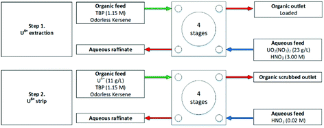 | ||
| Fig. 3 PUREX flowsheet performed sequentially on a cascade of 4 stages of 25 mm RD JAEA CCs.36 | ||
A uranium depleted aqueous nitric acid stream, referred to as the PUREX raffinate, is stored often in buffer tanks for further processing consisting of separating and partitioning the fission products. The isolated uranium laden solvent is stripped of uranium by contacting with dilute nitric acid, again performed in a cascade of 4 CCs.
The hydrodynamics of a cascade of four stages of 25 mm RD CCs was tested using a discrete aqueous feed composition in the absence of a fission product simulant. In this work over several solvent/aqueous ratios (0.03–30) and total flow rates (2–12 L h−1), U's extraction and back extraction performance was investigated, exhibiting very high stage efficiencies. However, this paper aims to learn more about solids, precipitates or third phase formation in flowsheet trials, and in this work, none were reported. The phenomenon of third phase formation arises due to the limited solubility of the metal–ligand complex in the non-polar organic phase in proximity to an aqueous phase with high loadings of heavy metals, and this results in the organic phase at the interface consolidating high concentrations of heavy metal and ligand whilst at the same time as depleted in solvent.37 The resultant precipitated metal–ligand inorganic complex suspended adjacent to the aqueous phase is reported as third phase formation.
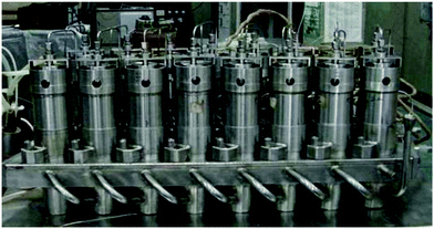
The Advanced Centrifugal Contactor Test System (ACT) is an engineering test facility at JAEA; early work demonstrated 50 and 80 mm RD CCs, with designed for remote maintenance and mal-operation testing alongside advanced CCs of internal circulation type with magnetic bearings, reported in a comprehensive conference paper in 2005.39 A cascade of 34 stages of 80 mm contactors and was demonstrated in 2009. The ACT consists of a three-story structure with the contactor cascade system located on the second floor, shown in Fig. 4, which was designed to achieve a throughput of 10 kg HM h−1. The results from several PUREX trials in 2009, Fig. S1 (ESI†), did not report solid precipitation or third phase formation.38
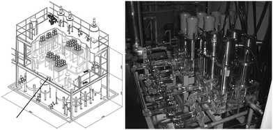 | ||
| Fig. 4 JAEA ACT facility and CC setup.38 | ||
In 1993 The Atomic Energy Authority Technology company based in Harwell and Culham in the UK, which since 2001 has become part of the UK Atomic Energy Authority (UKAEA), is the earliest available report of the UK testing centrifugal contactor, which was manufactured by Oak Ridge National Laboratory. A single block of stainless steel was machined to house 4 stages of the 55 RD CC, was combined to form a cascade of 12 stages.
The PUREX flowsheet was examined over two discrete flowsheets (Fig. S2, ESI†), the first consisted of a dual extraction of uranium and plutonium from non-active caesium with a scrub section, and the resultant heavy metal ion loaded solvent phase was fed into a second flowsheet to perform the stripping of uranium and plutonium. High efficiencies were achieved, with aqueous entrainment in the loaded heavy metal ion solvent of <1 vol% and scrubbing decontamination factors greater than 105 were achieved for caesium. No formation of third phase or precipitates were reported.
The UK National Nuclear Laboratory (UKNNL), formerly British Nuclear Fuels Limited (BNFL), performed a series of investigations to assess the effectiveness of advanced PUREX flowsheets for the control of Np and Pu using acetohydroxamic acid (AHA, Fig. 5).18,40–42 In a conventional PUREX flowsheet, Pu and Np are separated from the organic phase by reductive stripping. In an advanced PUREX flowsheet, ‘stripping is achieved by forming strong hydrophilic complexes with tetravalent actinides in nitric acid solutions.43’
The extraction of U and Np, partitioning by complexation using AHA was studied using a single 10 mm contactor, again using discrete aqueous feed compositions devoid of fission products.18 For extraction, a U and Np loaded aqueous solution of HNO3 was contacted with 30 vol% TBP in OK. For complexation, the U and Np loaded organic was contacted with an AHA–HNO3 solution, shown in Scheme 3 and Fig. 6. This provided the foundation for further work which aimed to understand Np routing in a typical PUREX flowsheet.
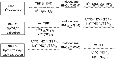 | ||
| Scheme 3 Sequential chemical extraction and separation of U and Np.18 | ||
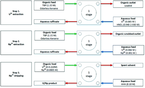 | ||
| Fig. 6 Advanced PUREX flowsheet for U/Np complexation using AHA performed on a single 10 mm CC.18 | ||
Using a cascade of 20 stages of 10 mm RD Chinese INET CCs modified with long rotors, formed an extract/scrub section.41 An organic phase loaded with U and Np was contacted with an aqueous phase of HNO3. Finally, using a cascade of 12 stages 10 mm RD Chinese INET contactors, the effectiveness of the complexation of AHA with Np was assessed.40 An organic phase loaded with U and Np was contacted with aqueous HNO3 and AHA, successfully demonstrating the process, Fig. S3 (ESI†). As a result of the interaction of U, Np, a TBP-solvent solution and an HNO3–AHA solution, no solid precipitation or third phase formed.
To understand Pu distribution via complexation with AHA, several Advanced PUREX flowsheets were configured using up to 30 stages of 10 mm RD Chinese INET CCs, Fig. S5 (ESI†).40,41 A discrete aqueous feed compositions devoid of fission products of U and Pu in HNO3 was contacted with an organic phase consisting of 30 vol% TBP and D80. This was subsequently contacted with AHA and HNO3. Three trials were carried out with feeds of varying Pu wt% representative of MOX fuels (7 wt% Pu, Fig. S8, ESI†), fast reactor fuels (20 wt% Pu, Fig. S9, ESI†) and Pu-residue processing (40 wt% Pu, Fig. S10, ESI†). No solid precipitation or third phase formation was reported due to the interaction of U, Pu, HNO3–AHA solutions or TBP–D80 solutions.
Several methods exist for the reductive extraction of Pu4+ to Pu3+, with early PUREX plants utilising ferrous sulphamate (Fe2+(NH2SO3)), which produces a salt–laden raffinate.44 A salt-free reducing strip agent hydroxylamine nitrate (HAN) is considered more suitable for flowsheets with higher Pu concentrations, such as those designed to reproduce fast reactor fuels. The reaction is as follows:
| 4Pu6+ + 2NH3OH → 4Pu3+ + N2O + H2O + 6H+ |
To facilitate a comparative assessment of Pu and Np partition performance from U using AHA, Pu and Np reductive extraction from U using HAN was investigated.40 Using a cascade of 30 stages of 10 mm RD Chinese INET contactors, Fig. S4 (ESI†), a solution of U (92 wt%), Pu (7 wt%) and Np (0.04 wt%), representative of Mixed Oxide (MOX) fuel, was contacted with a solution of 30 vol% TBP in D80. This was subsequently contacted with a solution of HNO3 and HAN. As a result of the interaction of U, Pu, Np, HNO3, TBP–D80 solutions and HNO3–HAN solutions, no solids or precipitates were reported. The next step in development being undertaken by the UK NNL is to produce the Advanced PUREX flowsheet encompassing Tc rejection in a single cycle solvent extraction process.45
NEXT
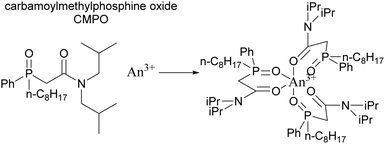
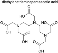
The JAEA is developing the Next Extraction System for Transuranium (TRU) Recovery (NEXT) reprocessing flowsheet for the co-recovery of U, Pu and Np using TBP,24 and Am and Cm using either extraction chromatography or solvent extraction using the Solvent Extraction for Trivalent f-elements Intra-group separation in n-octyl(phenyl)-N,N-diisobutylcarbamoylmethylphosphine oxide (CMPO)-complexant System (SETFICS) process.46,47 In the SETFICS process, spent fuel liquor is contacted with a solution containing TBP and CMPO which causes the extraction of U, Pu, Np, Am and Cm, shown in Scheme 4. The organic phase is then contacted with diethylenetriaminepentaacetic acid (DTPA), which selectively stripped the trivalent actinides, shown in Scheme 5.In 2012, three trials were performed by the JAEA using a cascade of 16 stages of 100 mm RD CCs, Scheme 6, using dissolved irradiated core fuel of the “JOYO” fast reactor. It should be noted that dissolved fuel was subjected to a bubbling stream for NO2 to maintain Pu4+ oxidation valence and was filtrated through a one μm glass filter to remove any insoluble solids.
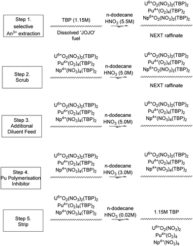 | ||
| Scheme 6 NEXT ‘RUN2’ sequential chemical extraction and separation of U, Pu, Np from irradiated fuel.46 | ||
Fig. 7 shows the second flowsheet performed, which had a double scrub. It was reported that in the stripping section, the polymerization of the Pu4+ in the high Pu concentration region was observed and that a small amount of a 3.00 M HNO3 solution was supplied to prevent Pu-hydrolysis.46,47
 | ||
| Fig. 7 NEXT flowsheet ‘RUN2’ performed on a cascade of 32 stages of 100 mm RD CCs.46 | ||
‘Nearly all the Np was extracted with TBP at the co-decontamination section in all runs, [however] the Tc scrub flowsheet of RUN3 is rather complicated, and further experimental investigation into the decontamination of Zr and Tc is required to design a simpler system.’46
In 2007, Japan Atomic Energy Agency (JAEA) performed four trials, listed in Table 1, of the NEXT and SETFICS flowsheets in centrifugal contactors. The fuels were fast reactor fuel ‘‘JOYO’’ supplied by JAEA, and high flux reactor fuel supplied by EURATOM. The SETFICS flowsheet was divided into two parts (A and B) due to apparatus limitations. No third phase formation or solid precipitates were reported; however, 3.00 M was reportedly used to suppress the Pu(IV) polymerisation in the stripping section.47
| Run | Process | Feed | Contactor | Facility |
|---|---|---|---|---|
| 1 | NEXT | Fast reactor fuel ‘‘JOYO’’ supplied by JAEA | 16 × 25 mL JAEA | CPF |
| 2 | NEXT | High flux reactor fuel supplied by EURATOM | 8 × 10 mm INET | ITU |
| 3a | SETFICS | Raffinate from RUN1 | 16 × 25 mL JAEA | CPF |
| 3b | Acid waste from RUN3a | 16 × 25 mL JAEA |
TRUEX
The TRansUranic EXtraction (TRUEX) process, developed at Argonne National Laboratory (ANL), is based on the PUREX but modified to facilitate the removal of Am and Cm as well as U and Pu from HAW. The process consists of five steps, shown in Scheme 7. First, the highly active feed is contacted with the TRUEX solvent, which consists of a solution of CMPO, shown in Scheme 4, and TBP in an organic solvent.48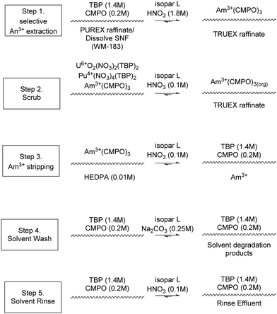 | ||
| Scheme 7 Chemistry employed in TRUEX flowsheet.51 | ||
Next, the organic phase is scrubbed using Al(NO3)3 to remove any fission products that may have been extracted into the organic feed. The third stage consists of an americium strip using dilute HNO3 removing >99% of the Am. The fourth stage consists of a Pu strip using (NH4)2CO3, removing >99% of the Pu and the remaining Am. The fifth stage consists of two washes of the organic solvent using Na2CO3. The process produces a total of 5 product streams; a non-transuranic loaded raffinate, americium stream, plutonium stream, the carbonate wash waste and acid rinse waste.
In 1997, ANL reported TRUEX flowsheets performed on a cascade of 20 stages of 40 mm ANL CCs.49 The report provides details on many aspects of preparation, solvent regeneration and wastes generated. The authors report in the first flowsheet, shown in Fig. 8, upon startup a spike in alpha activity in the raffinate. Although the procedure was modified, the peak could only be reduced and not eliminated. In the same trial, precipitation of plutonium oxalate occurred within the strip section's first stage, stage 15.
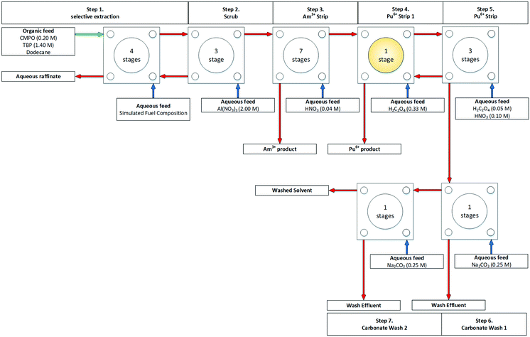 | ||
| Fig. 8 TRUEX flowsheet demonstration performed on a cascade of 20 stages of 40 mm RD CCs.49 | ||
Removal and recovery were attempted by washing with nitric acid and ammonium oxalate to dissolve the precipitate, of which the latter was more effective. The second flowsheet, shown in Fig. S12 (ESI†), replaced the two oxalic acid feeds (0.335 M at stage 15 and 0.050 M at stage 18) with a single ammonium oxalate feed (0.280 M at stage 18). Solvent recycling and regeneration were also demonstrated, which utilised a packed bed column of alumina and 1 micron filters.
Idaho National Lab (INL), previously known as Idaho National Engineering and Environmental Laboratory (INEEL), began commercialising annular centrifugal contactors in 1990 with a technology transfer patent.50 In 1996, Law and co-workers tested a TRUEX flowsheet, Scheme 7, on a cascade of 20 stages of 20 mm RD CCs in a shield cell facility, Fig. S13 (ESI†).51
A subsequent TRUEX flowsheet was performed two years later, and again no precipitate and third phase was observed, Fig. 9. However, between tests, it was mentioned that after shutdown, ‘re-equilibration of the solution drained from stage 11 (strip product stage) resulted in the formation of a white precipitate.’52 The precipitate was reported to likely be Am and Pu inorganic complex due to poor mass balances for these elements, however, the results from the flowsheet solution samples taken for alpha spectrometry showed >99.8% removal efficiency.
 | ||
| Fig. 9 TRUEX flowsheet demonstration with stage 11 in the stripping step highlighted in which an Am and Pu inorganic complex precipitate was collected.52 | ||
In 1999, INL researchers presented another TRUEX flowsheet at the Waste Management conference, shown in Fig. S14 of the ESI.†![[thin space (1/6-em)]](https://www.rsc.org/images/entities/char_2009.gif) 53 In the 0.01 M HEDPA strip stages of a cascade of 20 stages of 20 mm RD CCs, a ‘slight precipitate’ was discovered, which had not formed during 0.04 M HEDPA pervious flowsheet. The precipitates are presumed to be Am and Pu, due to the low material balances upon completion of the flowsheet.
53 In the 0.01 M HEDPA strip stages of a cascade of 20 stages of 20 mm RD CCs, a ‘slight precipitate’ was discovered, which had not formed during 0.04 M HEDPA pervious flowsheet. The precipitates are presumed to be Am and Pu, due to the low material balances upon completion of the flowsheet.
In 2010, Law and co-workers again at INL performed a TRUEX flowsheet on a cascade of 30 stages of 50 mm RD CCs, reported as pilot-scale rather than laboratory scale. They did not report any precipitation nor third phase formation whilst achieving >99.9% separation of all lanthanides from simulated fission product aqueous feeds over 174 minutes.54
DIAMEX
The first of the flowsheets that further process the waste from a PUREX process, known as PUREX raffinate, is diamide extraction (DIAMEX).55 These secondary follow-on flowsheets will produce different solids than those that process Highly Active Spent Nuclear Fuel feeds.The flowsheet is designed to extract trivalent actinides and lanthanides from a PUREX raffinate using malonamides, Scheme 8.56 The process consists of four steps, extraction, two scrubs and an actinide and lanthanide strip. The feed to the process, consisting of a PUREX raffinate containing fission products, nitric acid and oxalic acid is contacted with a solution containing a malonamide in an organic solvent. The organic product is then scrubbed, first with a solution of nitric acid and oxalic acid and secondly by a solution of nitric acid. The product of this is then stripped of actinides and lanthanides using a solution of nitric acid.
In 2000, Malmbeck and co-workers performed DIAMEX using dimethyl dibutyl tetradecyl-1,3-malonamide (DMDBTDMA) on a cascade of 16 (assumed 10 mm RD INET) CCs. They reported no precipitation or third phase formation.55,58 In 2005, Serrano-Purroy and co-workers performed DIAMEX, Scheme 9, on a cascade of 16 stages (assumed 10 mm RD INET) CCs, Fig. 10.57 The flowsheet was being developed to partition minor actinides from highly active aqueous feed solutions. The flowsheet extracts 99.5% Am and 99.7% Cm whilst preventing the co-extraction of molybdenum, zirconium and palladium.
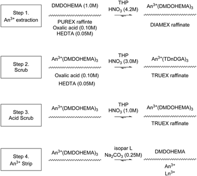 | ||
| Scheme 9 DIAMEX solvent extraction chemistry implemented in centrifugal contactor cascade.57 | ||
 | ||
| Fig. 10 DIAMEX flowsheet performed on a cascade of 16 stages of assumed 10 mm RD CCs.57 | ||
The aqueous acid concentration was followed across the cascade with inter-stage sampling, and optimisation determined that the minimum value of nitric acid was 0.3 M, and below <0.3 M third phase formation occurred in the acid scrubbing of the organic phase. Modolo and co-workers performed DIAMEX on the same cascade and noted that ‘lower scrub acidity must only be considered with care to avoid lanthanide oxalate precipitation, since the aqueous lanthanide concentrations are high in the scrubbing section.59’ The effect of solids on CC performance was not reported.
SANEX
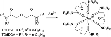
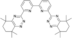
The Selective Actinide Extraction (SANEX) treats PUREX raffinates to extract trivalent actinides (Am and Cm). There are several variations, all of which use diglycolamide (DGA) ligands, see Scheme 10, that preferentially extract trivalent actinides over tetra- and hexavalent actinides.60 Generally, a PUREX raffinate containing both lanthanides and actinides is first contacted with DGA extracting the trivalent actinides, scrubbed to remove any extracted fission products and then the trivalent actinides are stripped.The have been three versions of SANEX performed in CCs which are:
• I-SANEX
• R-SANEX
• JAEA-SANEX
Each of these will be discussed separately.
I-SANEX
The Innovative Selective Actinide Extraction (I-SANEX) is a uses N,N,N′,N′-tetraoctyl diglycolamide (TODGA), see Scheme 10. The desired outcome was that TODGA would selectively coordinate to trivalent actinides removing them from a PUREX raffinate, then solvent phase loaded with trivalent actinides was stripped to produce an aqueous product that only contained trivalent actinides. The CEA developed I-SANEX to simplify DIAMEX/r-SANEX combined process.Modolo and co-workers performed two I-SANEX flowsheets. with. The flowsheet, shown in Scheme 11, used cascades of 16 or 24 stages of 10 mm RD INET CCs.61 They achieved greater than 99.8% extraction of trivalent actinides. Their trivalent actinides aqueous product contained <2% Pd, Mo and Sr. However, undesirable precipitation of solids occurred during the development of this I-SANEX flowsheet in CCs. It was discovered in the second test, using 24 stages, shown in Fig. 11, that high oxalic acid concentrations (>0.4 M) were required to suppress Zr and Mo's extraction and suppress third-phase formation. This resulted in stages 8, 9, and 10 becoming coated in crystalline precipitates, which consisted of lanthanides according to ICP-MS.61
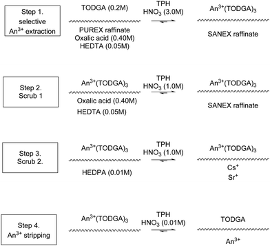 | ||
| Scheme 11 I-SANEX solvent extraction chemistry that generated precipitates.61 | ||
 | ||
| Fig. 11 SANEX flowsheet on a cascade of 24 stages of 10 mm RD INET CCs, step 2 (scrub 1) highlighted in yellow, indicating where precipitate accumulated.61 | ||
Modolo and co-workers in 2007 performed a trial on a cascade of 16 stages of 10 mm RD INET CCs, and another which consisted of two runs across the cascade to simulated a 32 stage cascade.62 In the first trial, Fig. 12, on 16 stages, the feed solution illustrated in blue, it was reported that precipitation of the lanthanide oxalates was avoided by restricting the concentration to oxalic acid in the first step of the extraction flowsheet. In addition, acidity and oxalate concentration in the fission product (FP) scrub solution was optimized to avoid precipitation in the subsequent six centrifugal extractors in the first scrub section (Scheme 11), which are also highlighted.
 | ||
| Fig. 12 First of two flowsheets for the first TODGA/TBP test on a cascade of 16 stages of 10 mm RD CCs.62 | ||
The second of the two flowsheets produced similar results to those obtained in the first flowsheet, shown in Fig. 13. Again the feed concentration in the selective actinide strip (step 1) was kept at 0.2 M oxalic acid to avoid precipitation in the first four contactors which contact the organic phase for the first time. No precipitation was reported in step 1, or in the subsequent primary scrub step in which the concentration of oxalic acid is increased to 0.5 M.
 | ||
| Fig. 13 Second of two first of two flowsheets for the first TODGA/TBP test on a cascade of 28 stages of 10 mm RD CCs.62 | ||
This was also combined with work from Geist and Modolo in which TBP was substituted with 1-octanol to reduce the nitric acid co-extraction.63 SANEX was then employed in a single stage 10 mm RD INET centrifugal contactor at 4200 rpm on the hot extraction of americium and europium, no solids were reported in this trials.64 This work was extended and performed using genuine dissolved reactor fuel liquor on a cascade of 16 stages of 12 mm diameter (RR BXP012) CCs with no reported solids, precipitation or 3rd phase formation on this scale.65,66
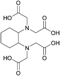
Sypula and co-workers concurrently examined trans-1,2-cyclohexanediaminetetraacetic acid (CDTA), see Scheme 12, as a substitute for oxalic acid, in the preparation of a SANEX sequential flowsheet being performed in a single 10 mm INET CC, shown in Fig. S15 (ESI†).67 The substitution was implemented to circumvent forming lanthanide oxalates that can form precipitates and suppress the extraction of Pd and Zr.
R-SANEX68
The Regular SANEX (R-SANEX)68 flowsheet has two distinct differences from the I-SANEX. The aqueous feed in R-SANEX has undergone PUREX and DIAMEX extractions and uses CyMe4–BTBP, see Scheme 13, in combination with TODGA to extract the trivalent actinides and the use of glycolic acid in the stripping of the trivalent actinides. The use of CyMe4–BTBP in R-SANEX improves upon I-SANEX, which requires aqueous buffering agents to maintain the acidity range for efficient actinide.A single stage 55 mm RD CC fed with synthetic PUREX raffinate demonstrated the ‘selective extraction of trivalent actinides’ was possible.20
Several batch mode experiments producing precipitates have been reported. These materials might be used to study in situ generated solids in flowsheets the affect hydrodynamics in CCs overtime. During tests in batch mode on 8 mL scale in the presence of high oxalic acid concentrations, slow precipitation of trivalent actinides and lanthanides was observed in the aqueous PUREX raffinate. Third phase formation was further suppressed when the flowsheet was modified further.69
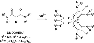
In another permutation of the flowsheet, Magnusson and co-workers in Karlsruhe Institut für Technologie (KIT) in Germany, a CyMe4–BTBP (0.015 M)/DMDOHEMA (0.25 M)/octanol system was performed on a single 12 mm RD CC. No precipitation was observed in the CCs, however, precipitates were produced in batch experiments performed on a vortex mixer over 10 minutes in a 2 mL sample vial.71 Using a cascade of 16 stages of 10 mm RD INET CCs, this flowsheet was conducted in two parts, and the scrub was further split into two. The selectivity and recovery of Am3+ was excellent and greater than 99.7%. However, for this flowsheet trial, no precipitates or third phase formation was reported.72
Two similar flowsheets in 1 mL scale batch mode, shown in Scheme 15, with a solvent–aqueous ratio of 1, was performed.20,73 This work initially generated ‘voluminous precipitates’ of L-cysteine complexed with Pd, Ag, Cd and Ba. The flowsheet was altered so that L-cysteine (0.01 M), Scheme 14, was only present in the third step (second scrub) so that the Pd raffinate was separate. The modification did not generate a precipitate or 3rd phase. ‘The solvent showed a high selectivity for trivalent actinides with a high lanthanide separation factor. However, the co-extraction of some fission product elements […] was observed.’73
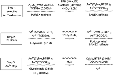 | ||
| Scheme 15 SANEX solvent extraction chemistry.20,73 | ||
In 2013 another SANEX flowsheet was performed in a smaller cascade, 8 stages of 10 mm RD INET CCs, using a PUREX highly active raffinate (HAR) as the aqueous feed, at 10–20 mL h−1 at 4500 rpm over two days. ‘It was demonstrated that a selective extraction and high recovery of >99.4% of the trivalent minor actinides [Am3+, Cm3+] was achieved with low contamination by fission products. The product contained 99.8% of the initial Am3+ and 99.4% of the initial Cm3+ content.’
At the end of both days, no precipitate or 3rd phase was reported.70 As Fig. 14 shows, the L-cysteine was introduced in step 3 rather than step 1. To avoid solid precipitation that had been reported two years earlier, Fig. S15 (ESI†).20,73
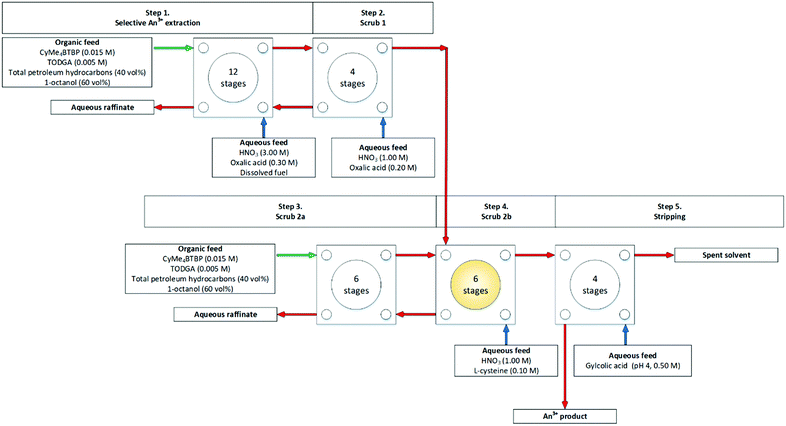 | ||
| Fig. 14 1-Cycle SANEX flowsheet performed on a cascade of 16 stages of 10 mm RD CCs.70 | ||
JAEA SANEX
The JAEA has investigations into a SANEX-like flowsheet for the partitioning of actinides from a PUREX using N,N,N′,N′-tetradodecyl-diglycolamide (TDdDGA), see Scheme 10. The flowsheet was developed for trivalent actinide recovery from a set of model fission products.The flowsheet was performed in 2016 on a cascade of 32 stages of 27 mm RD CCs.74 An alcohol, 2-ethyl hexanol (2EH) was added to the solvent shown in Scheme 16. With the aim for preventing precipitation in the back extraction stages in the flowsheet shown in Fig. 15. They reported good extraction efficiencies for trivalent actinides with a degree of co-extraction of Zr. It was reported that no entrainment was observed and that the centrifugal contactors. The SANEX flowsheet that was test was used N,N,N′,N′-tetradodecyl-diglycolamide (TDdDGA) upon a PUREX raffinate is shown in Scheme 10. A white precipitate was formed in the final four stages, shown in Fig. 16, but was not identified.
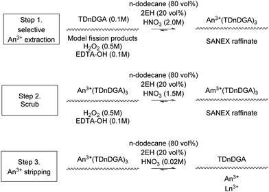 | ||
| Scheme 16 JAEA SANEX solvent extraction chemistry that generated precipitates, 2EH = 2-ethyl hexanol. | ||
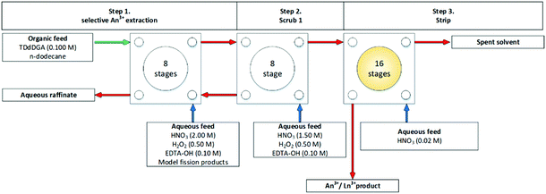 | ||
| Fig. 15 JAEA flowsheet performed on a cascade of 32 stages of 27 mm RD.74 | ||
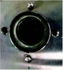 | ||
| Fig. 16 Bird's eye view into the housing with the rotor removed showing white precipitate settled in the mixing zone.74 | ||
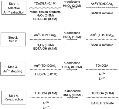
The JAEA performed another flowsheet, Fig. 18, on the same cascade to compare the extraction efficiency against mixer settlers.75 It is worth noting that the throughput of the centrifugal contactor was tenfold greater. The SANEX chemistry employed is shown in Scheme 17. A simulant PUREX raffinate of model FPs in HNO3 with H2O2 and EDTA–OH was contacted with an organic solution of TDdDGA with the organic product being scrubbed with nitric acid, H2O2 and EDTA–OH. The raffinate of this process is discharged, and the organic product of this process is fed forwards to the next cycle where it is stripped with dilute nitric acid, which is subsequently scrubbed with TDdDGA. Again, good extraction efficiencies for trivalent actinides with co-extraction of Zr was reported.
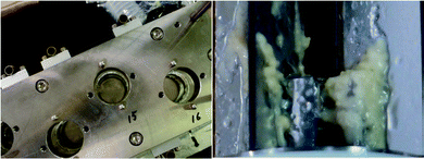 | ||
| Fig. 17 Left = looking down inside the housing with the rotor removed showing white precipitate settled in the mixing zone, right = white precipitate adhering to the inside of the rotor.75 | ||
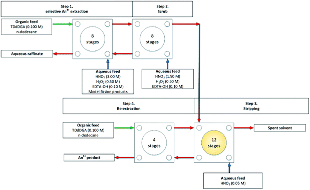 | ||
| Fig. 18 JAEA flowsheet performed on a cascade of 32 stages of 27 mm RD CCs.75 | ||
Again a white precipitate formed in the stripping section (the first four contactors of aqueous feed) and observed in the mixing zone (Fig. 17) upon removing the motor/rotor/bowl units. This time the material was qualitatively analysed by fluorescent X-ray and found to be primarily Zr, with Mo and Ru minor peaks.
UNEX
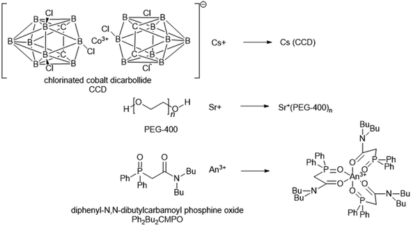
The Universal solvent extraction (UNEX) reprocessing process was developed to treat approximately 5 million litres of acidic, high activity liquid waste stored at the Idaho National Engineering and Environmental Laboratory (INEEL).76 The UNEX process is designed for ‘simultaneous separation of caesium, strontium, and the actinides from radioactive acidic tank waste.’77 The complexation agents (Scheme 20) chlorinated cobalt dicarbollide (CCD) for 137Cs, polyethylene glycol-400 (PEG-400) for 90Sr, and diphenyl-N,N-dibutylcarbamoyl phosphine oxide (Ph2Bu2CMPO) for extraction of actinides and lanthanides. The flowsheet results in a lower quantity of high active waste for disposal, and a low-level waste stream suitable for disposal as LLW by cementation. Initially para-xylene with octyldifluoromethyl sulfone was used as a solvent, which was soon replaced with phenyltrifluoromethyl sulfone (FS-13).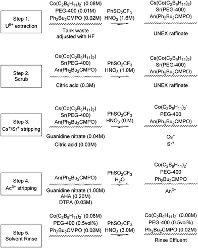 | ||
| Scheme 18 Sequential chemical extraction and separation of Cs+/Sr+ and An3+.78,79 | ||
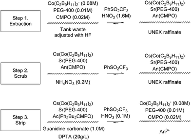 | ||
| Scheme 19 UNEX solvent extraction chemistry.83 | ||
During the process, high active liquor diluted in hydrofluoric acid is contacted with the UREX solvent, followed by scrubbing with a mixture of citric acid and nitric acid to remove extracted Zr and Fe. The solvent is then scrubbed using Guanidine Carbonate and DTPA to remove Cs, Sr and actinides from the solvent. The solvent is then washed using nitric acid to remove stripping reagents before the solvent is recycled.
In 1997, the first of six UNEX flowsheets, shown in Scheme 18, was performed using a cascade of 26 independent 33 mm RD CCs fabricated by the Research and Development Institute of Construction Technology (NIKIMT).78 A surrogate aqueous feed simulated wastes from reprocessing of spent nuclear fuel. It was reported that a Zr precipitate formed in the Cs/Sr strip section of the early test, Fig. 19.79
 | ||
| Fig. 19 UNEX flowsheet performed on INEEL cascade of 26 stages of 33 mm RD CCs.78,79 | ||
A further five tests were performed, with significant modifications summarised by Herbst et al.78 However, no precipitation was observed in the subsequent flowsheets with these improvements implemented,76,77,80–83 a run performed over 66 hours.77
In 2002, an experiment using a recycled organic solvent was performed in which degradation products are more likely to be present and pose a higher likelihood of precipitation. The contactor cascade was housed in a shield cell, and the flowsheet shown in Fig. S16 (ESI†), precipitates and third-phase formation were ‘never observed in the recycled organic solvent’83 in the chemistry implemented, show in Scheme 19.
SREX
The Strontium Extraction (SREX) process was developed at Argonne National Lab to remove Sr from acidic wastes and was utilised to process sodium bearings wastes (SBW) stored at the Idaho Chemical Processing Plant.84,85The process consists of three stages, extraction, strip and solvent recovery. During extraction, SBW is contacted with 4′,4′(5′)-di-(tert-butyldicyclohexo)-18-crown-6, Scheme 21, with the raffinate being disposed of as LLW, and the organic product being fed to a strip process. The strip consists of contacting the organic product with nitric acid producing a HAW raffinate. Finally, the organic solvent is re-acidified using nitric acid before recycling.
In 1997, a SREX flowsheet was performed on a cascade of 24 stages of 20 mm RD CCs (Fig. S18, ESI†), in which’ flooding, precipitate, and third phase formation were not observed during testing.’86 It has also been reported under the abbreviation SRTALK at ONRL, the flowsheet was performed on a cascade of 12 stages of 20 mm CCs in 1999 using a simulated alkaline-side tank waste aqueous feed, in which no precipitates were formed.87
A subsequent SREX flowsheet was performed using a cascade of 16 stages of 55 mm RD CCs, Fig. 20, and no problems with the desired extraction of Sr was encountered.84,88 The flowsheet achieved >99% Sr extraction. Pb was also extracted and accumulated in the SREX solvent, but a Pb precipitate was formed in the strip’ stages of the contactors. It was reported as suspended solids in interstage samples in significant quantities of the organic outlets, however, no masses were given. It was proposed that continued operation would have led to ‘resulted in a continued build-up’ of the precipitation.
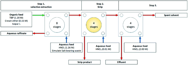 | ||
| Fig. 20 SREX flowsheet performed on a cascade of 16 stages of 55 mm RD CCs.84 | ||
The precipitate was determined to be the Pb-crown ether complex by X-ray fluorescence spectroscopy and defined as insoluble in both phases. The effect on mass transfer by these solids was not reported.
In 1997, Leonard and co-workers reported combining SREX with the Neptunium–Plutonium Extraction (NEPEX) process on a cascade of 20 stages of 20 mm RD CCs.89 At the end of the experiment, a sticky precipitate of strontium and crown ether was found in stages 11 and 12. In stage 11, the volume of precipitate was sufficient to prevent the rotor from rotating. The authors predict that the rotor had likely stopped spinning during the test. The precipitate was removed by dissolution in an ethanol solution and resulted in the implementation of 1-octanol in the flowsheet rather than the hydrocarbon Isopar-L solvent.
The following year, Wood and co-workers improved the flowsheet chemistry and shown in Fig. 21. The extraction of Pb was performed in the lab offline in batch. The Pb was extracted from the aqueous feed efficiently, and the strip was performed unsuccessfully. Very dilute HNO3 or water was used to overcome this. However, this resulted in the Pb dropping out of liquid phases as a precipitate once again, a thick white precipitate was formed, believed to be crown ether:Pb:nitrate complex.88
 | ||
| Fig. 21 SREX flowsheet performed on a cascade of 24 stages of 55 mm RD CCs.88 | ||
Miscellaneous
India has also been testing and scaling up centrifugal contactors for reprocessing. Fast reactor fuel reprocessing has been carried out at the Development Laboratory in Indira Gandhi Center for Atomic Research (IGCAR). Trials with active materials have been conducted in CCs in the Compact Reprocessing facility for Advanced fuels in a lead shielded cell, also known as CORAL, shown in Fig. 22.25 It has been reported that 35 mm CC have been operating for at least six years with several improvements during this time. ‘These units are remotely maintained using master-slave manipulator with occasional direct maintenance in glove boxes. High capacity units with bowls in the range of 55 mm, 150 mm, 360 mm, 500 mm and 1000 mm, some of them made from PVDF material, have been designed. Some of these units are planned for use in uranium recovery from phosphoric acid.’25 However, no further data in the literature is available on solid precipitation or third phase formation.Idaho National Labs have also performed the Trialkyl phosphine oxides, reported as the POR Process, and the Fission Product Extraction (FPEX) Process. The POR ligands are a mixture monofunctionalised phosphine oxides of differing alkyl or aryl substituents, designed to extract 3+, 4+, and 6+ Transuranic elements. The flowsheet was performed on a cascade of 24 stages of 20 mm RD CCs.53 The FPEX flowsheet demonstrated 4,4′,(5′)-di-(t-butyldicyclo-hexano)-18-crown-6, reported as DtBuCH18C6, for selective extraction of strontium, and Calix[4]arene-bis-(tertoctylbenzo-crown-6), reported as BOBCalixC6, for selective extraction of cesium, performed on a cascade of 30 stages of 33 mm CCs.90 No precipitation or third phase was reported. ANL have also demonstrated the caesium extraction (CSEX),91 Civex92 and Thorex92 flowsheets.
The URanium EXtraction (UREX) process is a variant of the traditional PUREX process, where the addition of AHA to the SNF aqueous feed before contacting with solvent results in the formation of aqueous complexes with Pu and Np.43 The solution was contacted with TBP as in conventional PUREX flowsheets; however, the presence of AHA complexes results in only uranium being extracted. With a CHON elemental composition, AHA is suitable for future reprocessing flowsheets as it does not add a salt bearing waste form to the Pu product. A variant of the traditional UREX process, UREX+, separated elements into the following groups; (U), (Tc), (Cs & Sr), (Pu & Np) (Am &Cm) and (rare earth fission products).93 It was demonstrated in parts on a cascade of 24 stages of 20 mm RD CCs at Argonne National Laboratory in US using simulated and actual spent nuclear fuel with no solids reported (Scheme 22).22
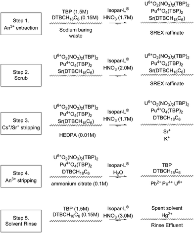 | ||
| Scheme 22 SREX solvent extraction chemistry implemented in centrifugal contactor cascade that generated Pb precipitates. | ||
The Cyanex 301 process, named after the mixture consisting predominant extract bis(2,4,4- trimethylpentyl)dithiophosphinic acid, also reported as HBTMPDTP) have been tested on a cascade of 20 mm ANL CCs94 and a cascade of 10 stages of 100 INET CCs95 ‘but the instability of the solvent makes it a poor choice for plantoperation.94’
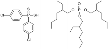
The separation of the adjacent trivalent actinides led to the development of the ‘Lanthaniden und Curium Americium’ (LUCA) process, for the selective recovery of Am3+ from aqueous nitric acid containing Cm3+ and Cf3+. ‘A mixture of 0.4 mol L−1 bis(chlorophenyl)dithiophosphinic acid and 0.15 mol L−1 tris(2-ethylhexyl)phosphate dissolved in 20% isooctane/80% tert-butyl benzene (Scheme 23) was used as the ligand.’96 The flowsheet was performed on a cascade of 24 stages of 10 mm RD INET CCs, which has also performed SANEX flowsheet,62 with no precipitation or third phase reported.96
Russian scientists have also investigated and developed centrifugal contactors for reprocessing.22 Russian centrifugal contactors are similar to the Savannah River Laboratory (SRL) CC design with paddle mixer under the rotor, unlike more contemporary CCs in which mixing occurs in the annular region due to Taylor–Couette flow.
Kuznetsov and co-workers reported CC designs for the continuous removal of solids from the heavy phase and remote servicing; these were reported as ETsRs (100–320 mm RD). ‘The outer walls of the rotor slope inward to form a cone that is truncated and the paddle mixer is attached in the region where the conical section is truncated. The rotor body is tapered in from the top to the bottom so that the solids settling out in the separating zone will be carried upward to the aqueous phase outlet. The outlet channels for the aqueous phase appear to be small so that the fluid velocities are greater to shear particle beds, so solids are re-suspended and entrained easily in the exiting aqueous phase. The concentration of the solids was reported up to 5 g L−1’.22
Kuznetsov and co-workers also reported a solid third phase formed when performing the co-extraction of Zr and Hf up to 3 g L−1. The 125 mm ETsT CCs facilitated the discharge of the precipitate, mainly in the raffinate, and also reported that there was a minimal disturbance of the hydrodynamic conditions.97 The INET in China produces miniature centrifugal contactors, of 10 or 20 mm RD. A flowsheet that has developed been developed in China is known as the Crown Ether Strontium Extraction (CESE) process,98 which is similar to the SREX process. It has been performed on a cascade of 16 stages of 10 mm RD CCs in a hot test using raffinate from TRPO trials.99–101 The was no precipitate or third phase formation observed. An improved total partitioning process was hot demonstrated on a cascade of 72 stages of 10 mm RD INET CCs over a long duration of 160 h.101 This sequentially performed an improved total partitioning process, including the TRPO process for the removal of actinides, the CESE process for the removal of Sr, and the calixcrown ether caesium extraction process for the removal of Cs, no precipitate for third phase reported at the end of the marathon flowsheet. The TRPO has also been demonstrated on a pilot plant scale cascade of 24 stages of 70 mm RD INET CCs upon simulated high level wastes uninterrupted for 72 h with no solids or third phase reported.102
An integrated AMP–PAN, TRUEX, and SREX has also been performed, combining ion-exchange in tandem with CC.29 In 2002, Herbst and co-worker undertook simulated reprocessing demonstration on 45 L of simulated acidic tank waste through three ion exchange columns packed with composite ammonium molybdophosphate–polyacrylonitrile (AMP–PAN) sorbent for Cs removal over 34 h. This was fed directly into a TRUEX flowsheet performed on a cascade of 23 stages of 33 mm rotor RD CCs over 71 h, shown in Fig. 23.29 The resultant TRUEX raffinate was further processed through a SREX flowsheet performed on the same cascade over a further 78 h.
 | ||
| Fig. 23 TRUEX section of an integrated AMP–PAN, TRUEX, and SREX performed on a cascade of 23 stages of 33 mm RD CCs.29 | ||
Monitoring the process for precipitation was performed during the TRUEX flowsheet, in which ‘stage 13 in the strip section and stage 19 in the carbonate wash section were opened and [visually] inspected for precipitates.29’ No precipitation or third phase formation was observed in the stripping section. ‘During visual inspection of the stage 19 contactor after approximately 4 h of operation, a slight band of rust/orange coloured precipitate was observed on the exterior of the contactor rotor. The solution in the contactor indicated no visible signs of precipitates. Based on previous experience, the precipitate was HgO.29’ It was quantitatively reported that the solid deposited in the contactor increased throughout the experiment.
The report proposes reducing the S/A ratio preventing the precipitation of HgO. The flow rate of the carbonate was implemented in the final 30 h to demonstrate this hypothesis and also evaluate if the deposited HgO could be dissolved. The result of a 5% increase of the carbonate wash indicated that the HgO precipitated did not dissolve, but the desired inhibition of further deposition was achieved, proving the primary hypothesis.
The mass of HgO precipitated was reported to be 3.71 g, and upon including it in the mass balance (making up 22% of the initially TRUEX feed concentration) resulted in ‘a 94.7% overall mass balance for mercury.’29 The authors state that ‘tributylphosphate (TBP) is added to the solvent as a phase modifier to prevent third phase formation.29’
The subsequent flowsheet performed on upon the actual TRUEX raffinate did not encounter any precipitation. The authors also state that contactors were operated without stopping or flooding, without interruption or alterations of the feed rates.103
In 1997, Leonard and co-workers produced a report of several laboratory-scale tests using CCs, one of which was a hot test of TRUEX combined with SREX, which was performed on a cascade of 20 stages of 20 mm RD ANL design CCs.89 It was reported that a bismuth oxalate precipitate was formed on the wall of a rotor, this also accounted for the low material balance found in the raffinate. No further operational details were provided in the report.
Summary of solids in contactors
The solvent extraction chemistries designed for reprocessing spent nuclear fuel demonstrated in CCs are comprehensively consolidated in this paper. However, a further concise set of tables allows further understanding of precipitates and third phase formation. Table 2 lists the flowsheets that were performed in CCs that generated solids. Due to the sample size and reporting, we cannot say that a specific flowsheet chemistry is more prone to solids formation. Solid precipitating is observed across all sizes and dimensions of CCs. A very useful observation from Chamberlian and co-worker is that even ‘the presence of unknown species, even at low concentrations, can […] significantly affect the operation of [a] flowsheet.’49 The table shows 8 different flowsheets and across the seven CC manufacturer designs. Precipitates were formed during demonstrations of flowsheets of simulated SNF compositions and during reprocessing of actual irradiated SNF. In addition, two entries included have found third phase formation in CCs for Zr and Hf extraction and upon re-equilibration of samples after separation in a CC cascade. In 12 of 15 reports the metal(s) present in the precipitates, and the authors have provided ligand in the flowsheets likely part of insoluble inorganic complex.| Flowsheet | Cascade | Manufacturer | Form | Solid | Assumed ligand |
|---|---|---|---|---|---|
| n/r = not reported.a Assumed, NIKIMT = Research and Development Institute of Construction Technology, Russia. | |||||
| UNEX78 | 26 × 33 mm | NIKIMT | During flowsheet demonstration | Zr precipitate | DBP |
| TRUEX52 | 20 × 20 mm | ANL | During re-equilibration | Undefined | Unknown |
| TRUEX53 | 20 × 20 mm | ANL | During flowsheet demonstration | Pu and Am precipitates | HEDPA |
| SANEX72 | 1 × 10 mm | INET | During flowsheet demonstration | L-Cysteine complexes of Pd | L-Cysteine |
| SANEX20,73 | 8 × 10 mm | INET | During reprocessing demonstration | L-Cysteine complexes of Pd, Ag, Cd, Ba | L-Cysteine |
| SANEX69 | 16 × 10 mm | INET | During reprocessing demonstration | Trivalent actinide and lanthanide precipitates | Oxalic acid |
| SANEX62 | 16 × 10 mm | INET | During flowsheet demonstration | Lanthanide oxalates | Oxalic acid |
| SANEX61 | 16 × 10 mm | INET | During flowsheet demonstration | Lanthanide oxalates | Oxalic acid |
| SANEX74 | 32 × 27 mm | JAEAa | During flowsheet demonstration | Undefined | Unknown |
| SANEX75 | 32 × 27 mm | JAEAa | During flowsheet demonstration | Zr, Mo, Ru precipitate | Unknown |
| SREX84 | 16 × 55 mm | ORNL | During flowsheet demonstration | Pd crown ether precipitate | Crown ether |
| SREX–NEPEX89 | 20 × 20 mm | ANL | During flowsheet demonstration | Sr crown ether precipitate | Crown ether |
| TRUEX–SREX89 | 20 × 20 mm | ANL | During flowsheet demonstration | Bismuth oxalate | Oxalic acid |
| Integrated AMP–PAN, TRUEX, SREX29 | 23 × 33 mm | NIKIMT | During flowsheet demonstration | HgO precipitate | N/A |
| Unknown15,22 | 1 × 100 mm | SRLa | During Zr and Hf extraction | Third phase | Unknown |
Further analysis of the isolated step of the telescoped reaction sequence that generates precipitates is shown in Table 3. Across the different flowsheet chemistries, the precipitates formed in the stripping step in all but one case which occurred in the scrubbing phase. The underlying chemical change is the rapid reduction in nitric acid concentration which may act as an anti-solvent and cause rapid ‘salting out’ of several inorganic complexes, or hydrolysis of nitrate species, for example, zirconium (4+) tetranitrate present in nitric acid which is soluble becoming zirconium oxynitrate that has a lower relative solubility. The key lesson learnt is that ‘the solvated metal complexes must be readily soluble in the solvent to prevent the formation of an immiscible third phase or solid precipitates,’ as stated by Herbst and co-workers.104 As part of flowsheet design, process conditions are selected to minimise maloperation, including subduing solid formation and third phase formation. This review has also captured successful chemistries that have been implemented listing the modification that prevents solid formation in centrifugal contactors and is reported in Table 4. The JAEA NEXT process has an additional stripping stage to allow the concentration of nitric acid to be reduced in smaller increments to prevent the polymerisation of plutonium dioxide. In a SANEX process, an additional stage to allow equilibration of Pd before complexation has been successfully implemented to inhibit the precipitation of the Pd complex with L-cysteine. Restriction of the oxalic acid concentration in SANEX systems has prevented lanthanide oxalates precipitating, and further recent developments have replaced oxalic acid all together with CDTA. The benefits of centrifugal contactors rapid mixing and reaction times comparative to a batch extraction in a classic centrifuge and avoid the slow precipitation of trivalent actinides and lanthanides reported when investigating the SANEX process. Integrated AMP–PAN, TRUEX, SREX29 demonstrated that simply altering the volumetric ratio within the contactor, by reducing the solvent/aqueous ratio, was sufficient in inhibiting further HgO formation. The non-polar solvent used extensively in flowsheets are less refined compositions of dodecane, known as kerosene. Substituting or adding a polar solvent has also been shown to be effective, in the SREX–NEPEX89 the kerosene non-polar hydrocarbon (commercially sold as Isopar-L was swapped entirely with 1-octanol, a polar fatty alcohol, which solubilised a Sr crown ether precipitates that form in hydrocarbon solvent. It has also been reported that non-polar solvent modifiers, such as diamyl amylphosphonate or TBP, have been used to suppress third phase formation.29
| Flowsheet | Step | Solid | Stage |
|---|---|---|---|
| UNEX78,79 | Cs/Sr strip | Zr precipitate | Rapid reduction in nitric acid concentration from 1.0 to 0.1 M HNO3, and addition of guanidine nitrate and citric acid |
| TRUEX52 | An strip | Undefined | Rapid reduction in nitric acid concentration from 0.1 to 0 M HNO3, and addition of HEDPA |
| TRUEX53 | Strip | Pu, Am precipitate | Rapid reduction in nitric acid concentration from 0.1 to 0 M HNO3, and addition of FHEDPA |
| SANEX61 | Scrub | lanthanide precipitates | Rapid reduction in nitric acid concentration from 1.0 to 0.1 M HNO3 |
| SANEX74 | Strip | Undefined | Rapid reduction in nitric acid concentration from 1.50 to 0.02 M HNO3 |
| SANEX75 | Strip | Zr, Mo, Ru precipitate | Rapid reduction in nitric acid concentration from 1.50 to 0.05 M HNO3 |
| SREX84 | Strip | Pd crown ether precipitate | Rapid reduction in nitric acid concentration from 2.00 to 0.01 M HNO3 |
| Integrated AMP–PAN, TRUEX, SREX29 | Carbonate wash | HgO precipitate | Rapid change in acidity |
| Flowsheet | Cascade | Manufacturer | Form | Solid |
|---|---|---|---|---|
| NEXT46 | 32 × 100 mm | JAEA | NO2 sparge to reduce Pu4+ oxidation state. Stripping concentration stepped down from 5 to 3 to 0.02 M HNO3 | Pre-emptively prevent PuO2 polymerisation |
| SANEX62 | 16 × 10 mm | INET | Oxalic acid feed restricted to >0.2 M | Pre-emptively prevent lanthanide oxalates precipitates |
| SANEX62 | 16 × 10 mm | INET | Oxalic acid feed restricted to >0.2 M | Pre-emptively prevent lanthanide oxalates precipitates |
| SANEX61 | 24 × 10 mm | INET | Oxalic acid feed restricted to >0.4 M | Suppress third-phase formation |
| SANEX67 | 1 × 10 mm | INET | CDTA substituted for oxalic acid | Pre-emptively prevent lanthanide oxalates precipitates |
| SANEX20,73 | 1 × 10 mm | INET | Split the scrub into two separate stages | Suppress Pd: L-cysteine precipitation |
| SANEX71 | 1 × 12 mm | RR | Performed in CC rather than centrifuge | Slow precipitation of trivalent actinides and lanthanides unable to form in residence time |
| Integrated AMP–PAN, TRUEX, SREX29 | 23 × 33 mm | NIKIMT | Reducing the S/A ratio of the carbonate wash feed, and ‘tributylphosphate (TBP) [added] as a phase modifier to prevent third phase formation29’ | Attempted to inhibit further precipitation of HgO |
| SREX–NEPEX89 | 20 × 20 mm | ANL | 1-Octanol substituted for Isopar-L | Solublise Sr crown ether precipitates that form in hydrocarbon solvent |
| TRUEX–SREX89 | 20 × 20 mm | ANL | Solvent modifiers were either diamyl amylphosphonate (DAAP) or TBP reported | ‘Phase modifier to prevent third phase formation’29 |
Investigation into solids in centrifugal contactors
As discussed in the introduction, highly active aqueous feed destined for aqueous separation flowsheets have been clarified to remove solids before solvent extraction. However, solids can form in the aqueous feed over time, during transitions in the chemical composition of a flowsheet, or not be removed in the clarification process. A few definitions are required to ensure the language used to describe the phenomena's is unambiguous. Solids suspended in fluids/solutions are referred to as slurries and require turbulent flow great enough to overcome gravity. In the absence of turbulence, gravity is the dominate force, and the solids settle as a bed, also known as a cake or a sludge. Introducing shear forces by increasing the average fluid velocity re-suspends the fluid's solids to create a slurry.Due to the nature of radioactivity and the workstations required to perform such chemistry, much of the early work establishing construction and hydrodynamics of centrifugal contactors in the presence of solids/slurries, has been performed in inactive chemical flowsheet. The simulants chosen have been summarised in Table 6. Webster and co-workers reported that the analysis of these solids has shown that mercuric sulfamate represents head-strained solids, specifically aluminium oxide, which remains undissolved during the dissolution stage of reprocessing entrains into the CCs highly active feed.12
| Exp 1 | Exp 2 | Exp 3 | Exp 4 | Units | |
|---|---|---|---|---|---|
| MnO2 concentration | 0.5 | 0.5 | 0.5 | 5.0 | g L−1 |
| Aqueous slurry feed rate | 38 | 76 | 38 | 38 | L h−1 |
| S/A ratio | 1 | 1 | 1 | 1 | — |
| Rotor speed | 1650 | 1650 | 1650 | 1650 | rpm |
| Centrifugal force | ∼430 | ∼430 | ∼430 | ∼430 | G |
| Duration | ∼20 | ∼20 | ∼20 | ∼20 | min |
| Retained Al2O3 | 6 | 13 | 25 | 20 | g |
| Solid simulant | Original solid | Head end/SX represented |
|---|---|---|
| Mercuric sulfamate106 | Aluminium nitrate | Small undissolved aluminium nitrate may escape clarification |
| Diatomaceous earth (SiO2)108 | SiO2 interfacial scums formed in mixer-settlers | ‘MnO2 and SiO2 both form interfacial scums in mixer-settlers’106 |
| Manganese dioxide13,105–107 | MnO2 interfacial scums formed in mixer-settlers | ‘MnO2 and SiO2 both form interfacial scums in mixer-settlers’106 |
| Aluminium oxide109,110 | Zirconyl molybdate | Formed in late-stage evaporation after solvent extraction |
Manganese dioxide and silicon dioxide are reportedly used as they form interfacial cruds in mixer-settlers during reprocessing solvent extraction operations. The aluminium oxide was chosen as the density was similar to in situ generated zirconyl molybdate, formed in evaporators at high temperatures and long reaction times, however, this is not found in the solvent extraction process. However, the information learned from these experiments is still relevant and will be discussed.
A point that must be made is that most of the flowsheets trailed up to this point rarely use recycled spent solvent in a second cycle. In industrial application spent solvent will be washed to reduce operation costs, however, it is known that solvent degradation also results in the formation of in situ generated solids (Table 7).
| Flowsheet | Cascade | Manufacturer | Form | Solid |
|---|---|---|---|---|
| n/a= not applicable.a Assumed. | ||||
| PUREX105 | 1 × 10 in | SRLa | Simulant for flocculent solids | Manganese dioxide |
| PUREX106 | 5 × 10 in | SRLa | Simulant for flocculent solids | Manganese dioxide |
| PUREX109 | 1 × 55 or 80 mm | JAEA | Simulant for zirconyl molybdate | Aluminium oxide |
| PUREX110 | 3 × 40 mm | RR | Simulant for zirconyl molybdate | Aluminium oxide |
| PUREX106 | 5 × 10 in | SRLa | Simulant for aluminium nitrate | Mercuric sulfamate |
| PUREX107 | 1 × 4 in | SRLa | Simulant for flocculent solids | Manganese dioxide |
| PUREX13 | 1 × 4 in | SRLa | Simulant for flocculent solids | Manganese dioxide |
| PUREX/UREX108 | 1 × 125 mm | SRLa | Simulant for entrained solids from head end | Diatomaceous earth (SiO2) |
Savannah river laboratory
The earliest work pumping suspended solids in the aqueous feed into centrifugal contactors was reported by Clarke in 1962.105 He performed 4 runs (Table 5) using a 254 mm (10 inch) RD single-stage CC of paddle design. Suspensions of 0.5 g L−1 of MnO2 (run 1–3) and 5.0 g L−1 MnO2 (run 4) were fed into a single stage without any notable effect. A cake formed only in the contactor rotor, and after equilibration (approx. 20 min) there was no additional increase in the mass retained, and there was no increase in power draw to the motor.Kishbaugh in at the Savannah River Laboratory, in 1963 described a 6-stage CC as a centrifugal mixer-settler, Fig. 24, as this design consisted of two parts; 254 mm (10 inch) RD CCs and 366 mm (14 inch) long separating zones.106 However, the flowsheet was undertaken on a cascade of 5 stages shown in Fig. 26 due to one motor malfunction on one of the contactors.
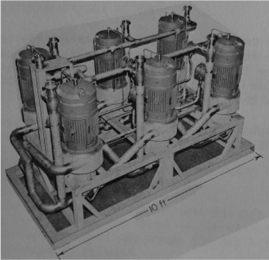 | ||
| Fig. 24 Kishbaugh's 6 stage 254 mm CC.106 | ||
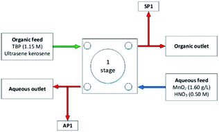 | ||
| Fig. 25 Suspended solids PUREX flowsheet performed on a 102 mm RD CCs.107 | ||
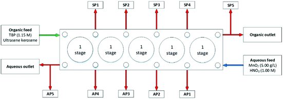 | ||
| Fig. 26 Suspended solids PUREX flowsheet performed on a cascade of 5 stages of 254 mm RD CCs.106 | ||
The two solids studied were manganese dioxide (MnO2) and mercuric sulfamate. The solid suspensions in 1 M HNO3 were maintained with good agitation and held at 43 °C. In the first test, freshly prepared MnO2 was reported to be relatively flocculent and settled very slowly in an aqueous medium. The feed solution was prepared by adding KMnO4 slowly to Mn(NO3)2 in 1.0 M HNO3 with a good agitation rate at 65 °C.
The experiment was performed over a period until steady state was reached, which was the point at which the outlet concentration from the cascade was equal to the inlet concentration (5.0 g L−1), although time was not reported. No solids were observed in the organic phase, and complete phase separation occurred throughout the experiment. However, each stage accumulated 2 kg of solid, and the mass captured did not increase the power to the motors.
The second test using 5.0 g L−1 mercuric sulfamate did not reach steady-state due to the feed solution being exhausted, the outlet concentration contained 1.3 g L−1 of suspended solids. “Solids are centrifuged out of solution and accumulate as a thin layer in each stage until the rate of re-suspension equals the rate of deposition into the aqueous phase at the underpass baffle; after that, the solids follow the aqueous phase through the bank. In contrast, many of these solids collect at the interface of pump-mix mixer-settlers until phase separation is greatly slowed”12
Argonne national lab
The work began in 1973 using 102 mm (4 inch) RD CC developed from the design used in Savanah River Laboratory.107 The PUREX flowsheet was employed with 1.6 g L−1 MnO2 in the aqueous feed, shown in Fig. 25.The experiment was run for a duration of time at which the MnO2 concentration in the effluent from the aqueous outlet was equal to the feed stream, and it was also noted that no solids were found in the effluent from the organic outlet. The bed that formed inside the rotor was determined not to affect the performance. The results shown in Table 8 showed that solids accumulated in the rotor section.
| Run 124A | Run 124B | Units | |
|---|---|---|---|
| MnO2 concentration | 2.6 | 2.4 | g L−1 |
| Total feed rate (A/O = 1) | 15.1 | 26.5 | L m−1 |
| Rotor speed | 2000 | 3500 | rpm |
| Running time | 70 | 85 | min |
| Aqueous throughput | 530 | 1135 | L |
| Retained MnO2 | 83 | 105 | g |
Argonne National Lab (ANL) further developed and tested the performance of a high-speed, long-rotor 102 mm RD CC for reprocessing short-cooled liquid metal fast breeder reactor fuels.13 In the tests evaluating effects of operability resulting from finely divided solids in the feed solutions did not encounter any operating difficulties. Two further experiments were performed using freshly prepared solid manganese dioxide (MnO2), from ammonium hydroxide (NH4OH) and potassium permanganate (KMnO4), which was reported to be moderately flocculent and settled slowly in aqueous solutions. The solvent was 30 vol% TBP in n-dodecane, and the aqueous phase was suspended MnO2 in aqueous 0.5 M HNO3, with a solvent/aqueous feed ratio of 1. The rotor speed and throughput were varied, the first run was performed at 2000 rpm rotor speed and 15.1 L min−1 (4 gpm) total throughput, the second run at 3500 rpm and 26.5 L min−1 (7 gpm) throughput.
Solid MnO2 was immediately observed exiting from the aqueous outlet, indicating that the solid did not initially settle in the contactors. The aqueous outlet was sampled periodically to determine the concentration of MnO2, the concentration equalled to the concentration in a feed solution after 30 minutes of operations. No solids were observed in the effluent from the organic outlet throughout the experiment. At the end of each test, the contactors were flushed to re-suspend and elute the solids that had accumulated within them; first with water, then with a solution of oxalic acid in nitric acid.
The results showed that relatively low masses of solids were retained in the contactor, shown in Table 8. It was also reported there were no mechanical difficulties encountered.
It was reported in this work that the outlet pipping was equipped with stainless steel wire wool filters to remove extraneous solids, however during solid tests, the filter was removed from the aqueous supply pump line to avoid separation of MnO2, from the aqueous feed.
The ANL design for the underflow uses long tubes or slots so that the riser is narrow and creates a high liquid velocity up to the upper weir, which carries out any fine suspended solids that might be brought into the contactor by the feed solutions. The narrow riser creates a strong Coriolis effect that makes the liquid level over the upper weir higher.’8,111
Japan
Work in Japan by Sakamoto and co-workers undertook experiments with 55 and 80 mm CCs.109 The research investigated cake formation inside two rotors that had different confinement volumes. Aluminium oxide (Al2O3, mean particle size ∼1.0 um, 3.99 g mL−1 density) was chosen as the suspended solid due to its similar density to molybdenum zirconium hydrate (4.00 g mL−1 density). The experiments, Table 9, demonstrated that cake formation occurs over time until reaching a maximum mass, and the cake did not affect the phase disengagement in this design of CC.| Exp 1 | Exp 2 | Units | |
|---|---|---|---|
| Contactor rotor diameter | 55 | 80 | mm |
| Al2O3 concentration | 15 | g L−1 | |
| Aqueous slurry feed rate | 17.5 | 44.0 | L h−1 |
| Duration | Approx. 300 | min | |
| Rotor speed | 4000 | 3500 | rpm |
| Centrifugal force | 500 | 500 | G |
| Retained Al2O3 | ∼400 | ∼1500 | g |
The concentration of Al2O3 at the outlet was measure using a turbidity analyser, and the mass captured was measured gravimetrically.109 After 5 minutes of operation, an additional at-line measurement to determine the particle size caught in the two contactors showed that the distribution uptake was not affected by the rotor's diameter. For the two diameters, the masses retained in the rotors were achieved within 300 min, reported approximately as 400 and 1500 g in the 55 and 80 mm CC respectively. The rate of Al2O3 accumulation was consistent over time until reaching these masses, shown in Fig. 28. The greater force inside the rotors was the gravitational force approximately 500 G, which resulted in solids forming a cake along the inner rotor's outer walls. The cake formed reduces the volume in the rotor in which phase disengagement occurs.
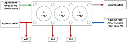 | ||
| Fig. 27 Suspended solids PUREX flowsheet performed on a cascade of 3 stages of 40 mm RD CCs.110 | ||
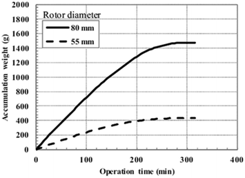 | ||
| Fig. 28 Sludge accumulation weight over time.109 | ||
Upon determining the bed formation depth, the Japanese team then further simulated bed formation of a specified volume of the rotor using metal inserts. The metal inserts were reported as percentages of the rotor volume; 0, 10, 30, 50% of CC rotors. This approach reduced the downtime between experiments, as this avoided using suspended solids which avoided an additional step flushing the contactors to remove said solids. For PUREX flowsheets with solvent to aqueous feed ratios of 1 and 2, entrainment was not observed with a 10 vol% simulated bed, however, as the simulated bed increased entrainment occurred with increasing magnitude, and was amplified as the diameter of the CC rotor was increased from 55 to 80 mm. The inlet flow rate was also examined between 30 and 250 L h−1 to determine the residence time within the CCs, and the results showed that the 30 vol% simulated bed did not affect the residence time within the unit.
Sakamoto and co-workers performed the PUREX flowsheet using uranyl nitrate (23 g L−1) in nitric acid (3 M) aqueous phase with TBP (1.15 M) in n-dodecane.109 The rotor speed was 3500 rpm with the solvent: aqueous feed ratio of 1![[thin space (1/6-em)]](https://www.rsc.org/images/entities/char_2009.gif) :
:![[thin space (1/6-em)]](https://www.rsc.org/images/entities/char_2009.gif) 1 at flow rates of 60 L h−1. A simulated bed consisting of metal inserts of a percentage of the rotor's internal confinement volume was examined. The work used a bed depth of 30 vol% of the volume within the rotor. The work demonstrated that the reduced volume resulting from a simulated bed forming did not reduce the stage efficiency compared to normal operation over a 10 minute operating period, shown in Fig. 29.
1 at flow rates of 60 L h−1. A simulated bed consisting of metal inserts of a percentage of the rotor's internal confinement volume was examined. The work used a bed depth of 30 vol% of the volume within the rotor. The work demonstrated that the reduced volume resulting from a simulated bed forming did not reduce the stage efficiency compared to normal operation over a 10 minute operating period, shown in Fig. 29.
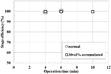 | ||
| Fig. 29 Extraction performance with and without simulated particle bed inserts.109 | ||
Work from this group using actual slurries also stated that: “The capture ratio of [slurries] in the contactor was measured as a function of particle size at various flow rates, rotor speeds, and contactor scales. The sludge adhered and accumulated inside the rotor as the operational time increased, and the operational conditions influenced the capture ratio of the sludge; a lower flow rate and higher rotor speed increased the capture ratio. The results confirmed that Stokes' law can be applied to estimate the experimental result on the behaviour of the capture ratio for centrifugal contactors with different scales”.112
UK
In 2019, Baker and co-worker also investigated the effect of suspended Al2O3 in an aqueous feed in a PUREX flowsheet was performed on a cascade of 3 stages of 40 mm RD CCs, shown in Fig. 27. The effect of particle size and concentration upon phase disengagement and the degree to which solids entrain in a cascade. Suspended solids that are pumped into CCs results in bed formation in the separator bowl.The suspended solids did not impact the phase disengagement of 1 M nitric acid and 1.15 M TBP in D-80 (Brenntag tradename of refined kerosene) at 20 L h−1 total flow rate with a rotor speed of 2000 rpm. Upon termination of the experiment, suspended solids settled in the mixing zone. Two steps were implemented to understand the nature of the slurries in centrifugal contactors. First, the contactors were drained the bottom valve to isolate the suspended solids. The contactors were flushed, dismantled and flushed again to separate the solids retained within the separating rotor.
The masses found in each contactor are shown in Table 10. However, a critical mass was not required, and entrainment of solids into the subsequent contactors was observed regardless of solids loading or size or experiment duration. This demonstrates that the fluid velocities in operation are sufficient to shear the particle beds during operations and that solids can potentially be removed.
| Exp 1 | Exp 2 | Exp 3 | Exp 4 | Exp 5 | Exp 5 | |
|---|---|---|---|---|---|---|
| C1 retained Al2O3 (g) | 7.97 | 12.57 | 52.92 | 2.84 | 27.80 | 53.25 |
| C2 retained Al2O3 (g) | 0.02 | 0.19 | 1.42 | 0.09 | 0.24 | 0.59 |
| C3 retained Al2O3 (g) | 0.12 | 0.01 | 0.27 | 0.01 | 0.18 | 0.06 |
| Suspended solid (g L−1) | 0.64 | 1.56 | 4.20 | 0.23 | 2.23 | 7.09 |
| Aqueous feed duration (min) | 76 | 49 | 78 | 76 | 76 | 45.6 |
This work's methodical approach provides insight into the sludge bed and slurry in the mixing zone at the termination of an experiment not previously discussed by the existing works reported above.12,13,105–107,109Fig. 30 shows the masses of solids recovered after each cleanout operation. Draining the contactor to determine the solids that had remained suspended contained was only >30 vol% of the mass. The flush method employed was found to be insufficient but showed some promise. However, most of the solids had formed a sludge that had adhered to the walls of the separation rotor, which required dismantling to remove them in all cases. This demonstrates that the majority of suspended solids form compact sludge beds with significant shear force to remove them. The mass transfer of nitric acid was also recorded at the end of these experiments. The results show the insoluble particles impact nitric acid extraction and is exacerbated with increasing concentration of particles in the feed to the contactors.
The authors state that this is counter-intuitive as most of the extraction would be expected to occur in stage 3 (C3) where the aqueous phase, in which >1% of the solids were present, is contacted with fresh unloaded solvent entering the contactors. The authors state further experiments are required to determining the effect of particle beds upon mass transfer.
Reprocessing plant application of centrifugal contactors
The previous sections demonstrate several routes by which solids may be entrained or form within a nuclear facility and understand the impact on CC performance. Having been successfully utilised in several nuclear facilities, the technical maturity of CCs has been demonstrated and adequate mechanisms for the management of unanticipated solid arising within the process developed. The commercial reprocessing facilities are shown in Table 11.| Commercial reprocessing facility | Operation throughput | Commissioned | Shut down |
|---|---|---|---|
| a Undergoing hot commissioning. | |||
| West Valley, NY, USA, | ∼275 MT per yearr | 1966 | 1972 |
| UP1, Marcoule, France | ∼400 MT per year | 1958 | 1997 |
| UP2, La Hague, France | 800 MT per year | 1976 | n/a |
| UP3, La Hague, France | 800 MT per yearr | 1990 | n/a |
| MAGNOX, Sellafield, UK | ∼1350 MT per year | 1964 | n/a |
| THORP, Sellafield, UK | ∼1100 MT year | 1994 | 2018 |
| Tokai-Mura plant, Ibaraki Prefecture, Japan | ∼200 MT year | 1975 | 2014 |
| Rokkasho plant, Aomori Prefecture, Japan | ∼800 MT per year | 2024a | n/a |
| Plant RT-1, Chelyabinsk Oblast, Russia | ∼400 MT year | 1976 | n/a |
Due to the sensitive nature of information concerning existing nuclear facilities' operation, the dissemination of information regarding the management of solids within contactors is limited. This section presents an overview and discussion of the available literature.
Savannah river
In 1970, Starks reported on the PUREX flowsheet implement on plant scale at the Savannah River Plant.26 The highly active feed was fed into a cascade of 18 CCs installed in batteries of 6, known as 6-packs. A 6-packs assembly, shown in Fig. 32 before installation in a hot canyon, would allow the access to a failure or associated piping by withdrawing a 6-pack and replacing it with another. The cascade of 18 stages of 250 mm RD CCs was implemented in the first of 3 cycles for processing irradiated fuel.
 | ||
| Fig. 31 Highly active PUREX flowsheet performed on a cascade of 18 CCs at SRL.26 | ||
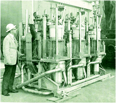 | ||
| Fig. 32 Centrifugal contactor 6 stage cascade assembly.26 | ||
The head end feed was typically targets, fuel slugs with a depleted core or natural uranium in an aluminium cladding. After clarification the dissolver feed removing undissolved material, the solution was adjusted before feeding into the first solvent extraction cycle. The highly active PUREX flowsheet was performed using a cascade centrifugal contactors is shown in Fig. 31.
To cope with mechanical failures, the control system installed initiates a controlled system shutdown of a contactor based upon vibration, temperature, or other indicators. If an individual contactor fails, the whole CC cascade will shut down immediately, including the bank's various feed systems. A controlled system shutdown, allows the CCs to be emptied of radioactive liquor, using drain and flush connections, provided at each contactor's bottom. They also allowed for flushing of the CCs internally, using the CINC clean in place system, which sprays process water, caustic, or HNO3 into the internal rotor, to facilitate contactor cleaning and flushing. The drained, flushed and cleaned CCs consequently have reduced radiation levels and allows operators access to the CCs operating area for repairs. This procedure enables the CCs to be cleaned in place and can also deal with potential blockages from solids. Before installation, the centrifugal contactors designed for use in the SWPF were tested in a prototype system using non-radioactive simulants and real waste at approximately one-fourth scale at Savannah River Laboratory. However, no solids in the CCs, either simulant slurry feeds or highly active feeds, have been reported.
Barnwell nuclear fuel plant
The Barnwell Nuclear Fuel plant was designed to reprocess 1500 metric tons of heavy metals per year. The construction was nearly completed, and testing with ‘cold’ with natural uranium has been performed at this facility; however, in 1977, the USA's policies changed to never reprocess commercial spent nuclear fuel due to its proliferation concerns.The plant employed PUREX flowsheets, highly active (HA) first cycle solvent extraction was to be performed in centrifugal contactors. A single multi-stage CC containing 10 internal stages from RR was used, although not reported the model is most likely the LX 670 N which would have been able to operate the flowrates used in the report (max 5500 L h−1). ‘The centrifugal contactor [was] used in series with the scrub column. The scrub column [was] designed as a dual extraction/scrub column, and is used in this dual operating mode when the process is operating on an installed highly active CC bypass piping system.’116
‘Cold’ testing was performed with aqueous natural uranium feed. The total flow through the centrifugal contactor, at flowsheet rates (5 MTU per day), was 3600 L h−1 at an aqueous to organic flow ratio of 0.42. Several important lessons relative to the operation and design of associated piping were learnt about the CC during this integrated cold testing. It was reported that upon testing, accumulation of in situ generated solids was encountered. Unfortunately, these solids were not identified and caused problems in the facility's commissioning, which resulted in changes to the contactors' design to make them more tolerant.116 The weirs in the contactor were altered to enable solids to be flushed through. Unfortunately, no specific information was available or reported on the type of solids that initiated the problems. The issues encountered were alleviated by increasing the flow rate through the contactor, most likely to increase the shear thinning of the unknown solids to re-suspend them. The aqueous transfer channels were subsequently modified, and an internal flushing system to permit routine flushing out of the channels was installed.
The final test was a two-phase operation using natural uranium as feed, and extraction efficiencies of >99.97% were achieved during this cold testing. Testing showed that the unit could handle flow rates at least 35% higher than those required by the flowsheet.
Plummer reported that the Barnwell Facility employed periodic operation of a flush system, even when bed formation was not observed. Some success in removing the bed that had formed was achieved ‘by repeatedly introducing solutions through the aqueous inlet while maintaining a low speed (approximately 300 rpm) and then stopping liquid flow and allowing it to drain. This procedure [provided] some temporary relief but is not as effective as the flush system.’116 Discussed earlier in this paper was the work performed by Sakamoto and co-workers using Al2O3 (15 g L−1) slurries, and cakes were formed in masses up to 400 g in the 55 mm CC and 1500 g in the 80 mm CCs respectively. It was reported that to remove the sludge accumulated attempts by washing with water while the rotors spun at low speeds for a few hours, however, no further details were provided. The group also stated that they were developing internal spray nozzles in the rotor to enable clean in place functionality demonstrated in USA.109
In 2007, Mann and co-workers began testing a single stage 127 mm diameter annular CC fitted with a clean-in-place (CIP) system, Fig. 33 middle & right.120 A suspension of 0.1 g L−1 diatomeous earth (mean particle size 80 micron and a density ∼2.4 g cm−3) was pumped into the contactor at various flow rates with the rotor at multiple speeds. At the end of the experiment, the rotor was stopped, and the CC was slowly drained to avoid dislodging the solids. Table 12 shows that >98% of solids are captured with varying flowrate and rotor speed. An interesting observation is that solids were observed to entrain and shown in the raffinate outlet stream (Table 13).
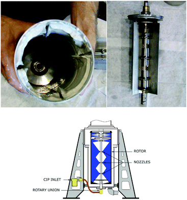 | ||
| Fig. 33 Left = bed formed on the wall of the rotor bowl, middle = schematic of nozzles, right = rotor with vanes and nozzles visible.108 | ||
| Measured flowrate (lpm) | Rotor speed (rpm) | Average outlet solid loading (g L−1) | Average capture (%) |
|---|---|---|---|
| 1.5 | 1750 | 0.00016 | 99.8 |
| 1.1 | 2300 | 0.00010 | 99.9 |
| 1.9 | 2900 | 0.00010 | 99.9 |
| 5.7 | 1750 | 0.00131 | 98.6 |
| 5.7 | 2300 | 0.00063 | 99.3 |
| 6.1 | 2900 | 0.00029 | 99.7 |
| 5.7 | 2900 | 0.00031 | 99.7 |
| 5.7 | 3500 | 0.00022 | 99.8 |
| 11.4 | 1750 | 0.00052 | 99.4 |
| 11.4 | 2300 | 0.00150 | 98.2 |
| 11.0 | 2900 | 0.00073 | 99.1 |
| 10.2 | 2900 | 0.00071 | 99.2 |
| 11.0 | 3500 | 0.00347 | 95.9 |
| CIP cycle | Pulse duration (s) | Sample vol (L) | Recovered solids | CIP efficiency |
|---|---|---|---|---|
| n.r. = not reported. | ||||
| First | 10 | n.r. | n.r. | n.r. |
| Second | 10 | 4.00 | 2.751 g | 97% |
| Third | 10 | 3.85 | 0.015 g | >99% |
| First | 15 | n.r. | n.r. | n.r. |
| Second | 15 | 4.11 | 2.854 g | 97% |
| Third | 15 | 4.15 | 0.015 g | >99% |
The bed formed in the contactors appeared to be uniform, and the bed formed in rotor bowl and weir assembly visible in Fig. 33 left. The bed formed along the wall of the contactor is uniform. The bed formed in the weir plate, although difficult to see, appears to be thinner than cake along the entire rotor wall. This is likely due to constriction and increased flow that sheers the bed and allows the effluent to flow. This may be a useful design characteristic when considering the separator zone.
The CIP methodology was as follows. First, the rotor was connected to a pump, water pumped at 25 L min−1 and 2.75 MPa through the rotor and out of the nozzles for a designated time, followed by two repetitions. The first CIP cycle was reported to have removed most of the solids, with 97% of solids removed after the first two cycles and 99% of solids removed after the third cycle. Increasing the duration of the pulse, from 10 or 15 seconds, did not further improve the efficiency of this CIP system.
In 2008, a further publication by Garn and co-worker reported the results of a larger single 127 mm annular CC with a clean-in-place solution.108 A slurry of 0.1 g L−1 diatomaceous earth was pumped into the contactor at several rotor speeds at several flow rates shown in Fig. 34. The percentage capture was calculated using the concentration of the solid that was eluted at the end of the experiment, shown in equation below:
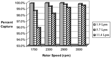 | ||
| Fig. 34 Percent capture as a function of flow rate and rotor speed.108 | ||
The capture rate of solids was dependent on both flow rate and rotation speed. However, a greater flow rate appeared to have reduced capture, which is most likely due to shorter residence times and increased shearing of the formed beds; this would have increased the solids' entrainment potential. The data also suggests the combination of lower g force at lower rotor speed with shorter residence time further reduces the accumulation of solids.
The clean-in-place modification consisted of several nozzles (impinging jets) down the length of the central rotor shaft. The bottom valve was opened, and water was pumped out of these nozzles at 25 L min−1 and 40 psig for either 10 or 15 seconds, three times. Elution from the bottom valve contained no solids after this process, and the removal of the bed was confirmed after dismantling.
CIP units have clearly been shown to be the most well documented and most effective method of removing solid beds formed in CCs.108 However, the environments in which CCs will be deployed will be highly active regarding radiation, and dismantling will have to be performed remotely. Remote disassembly his has been developed in industrial suppliers in collaboration with research labs and discussed in the next section.
A cascade of 3 stages of 127 mm RD CCs, Fig. 35, was constructed in a simulated highly radioactive environment (simulated hot cell) to develop remote handling expertise.121 The standard CINC V-05 CIP was modified for remote service; the connection to solution inlets, outlets, drain, and CIP component. Seven additional drain holes were introduced to the bottom plate, and a solids collector plenum was placed below the normal process fluids flow path, the design was designated V-05R.
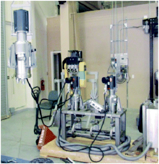 | ||
| Fig. 35 Centre position V-05R contactor unit removed from a cascade of 3 stages of 127 mm RD CCs in a simulated highly radioactive environment. | ||
‘Removal and replacement of the centre position V-05R contactor in the three-stage assembly was demonstrated using an overhead rail mounted’ master-slave manipulator (MSM) arm from PaR Systems. ‘Initial evaluation indicates a viable new design for interconnecting and cleaning individual stages while retaining the benefits of commercially reliable annular CC equipment. Replacement of a single-stage via remote manipulators and tools [took]; 30 min, perhaps fast enough to support a contactor change without loss of process steady-state equilibrium.’121 The test was performed on the 127 mm (CINC V-05), but the authors believe that this system could be scaled fourfold to the 508 mm (CINC V-20) CC model, capable of plant scale total throughputs up to 650 L min−1.
Removal of solids has also been achieved with the implementation of one-micron filters on a number of process stream on the ANL TRUEX demonstrations in 1997.49 Plugging was observed on the aqueous feed stream which led to the implementation of the filters being installed ‘the suction side of the pumps […] under a slight vacuum.’49
Conclusions
This review has consolidated the effect of performing solvent extraction processes sequentially, known as flowsheets, in centrifugal contactors (CCs) which deliver process intensification. This review builds upon the aqueous solvent extraction and chemical separation in discrete batch processes of many elements that comprise nuclear fuel reviewed by Leoncini and co-workers (also reported in Chem. Soc. Rev.).60 In the available literature many substrates and solvent compositions have been demonstrated from lab scale up to industrial scale. The second half of this review not only provides clarity on the subject of solid particulates that arise as a result of process intensification, but goes further to identify the underlying chemistry and how to manage them using industrail remote manipulation methods.The formation of solids in flowsheet testing occurs due to unexpected chemistry. In subsequent flowsheet developments, the potential for solid precipitation must be reduced so solids are not formed in ‘normal’ operating conditions. Though solids formation may occur in mal-operations. This review's central message is during short flowsheet tests, the amounts of solids encountered have largely not been reported to cause operational issues or reductions in solvent extraction efficiencies.
How solids behave in CCs
Several designs and sizes of CCs have been employed in solvent extraction, from lab scale to plant implementation for reprocessing spent nuclear fuel. Solids either enter the CCs in the aqueous feed as suspended solids or are formed in situ due to the solvent extraction process's chemical and physical composition.During operation, solids remain suspended in the CC mixing zone due to high turbulence, before being centrifuged out of solution by centrifugal force where they accumulate as a bed along walls of the separation rotor, accumulating as the operational time increases.
Solids in flowsheets
The majority of chemistry developed for future plant scale reprocessing has been performed in CCs, either in discrete single CCs sequentially simulating cascades, or in cascades of up to 72 CCs. The aqueous feed solutions have included; cold natural uranyl nitrate, simulated SNF compositions, and actual highly active dissolved SNF.Experience from flowsheet tests, increasing in size and complexity, was that in many cases, solids were not formed. In the cases in which solids have formed the duration of the experiment was not long enough for sufficient bed to develop and so the hydrodynamics and extraction efficiencies were not affected. Very few flowsheets have been performed with recycled/washed spent solvent, which are also known to be a source of generating in situ generated solids. ‘The presence of unknown species, even at low concentrations, can also significantly affect the operation of the flowsheet.’49
Analysis of the chemistry showed that the in situ generated solids predominately formed in the stripping stage in which there was a rapid reduction in nitric acid concentrations. The precipitates appear to form from unexplained chemistry that is undefined. Furthermore, the solids did not cause any issue during operation or reduction in extraction efficiency. The formation of solids is likely to be avoided by optimising the flowsheet. Iterative improvements of the chemical steps have been reported to inhibiting solid formation and demonstrated in CCs. Temperature-sensitive flowsheets, where a third phase could form as the temperature drops, temperature control could also improve solubility.
Slurries into CCs
Further investigation of the effect of solid accumulation is needed. Suspended solids, also referred to as slurries, have been fed directly into CCs. The four solids used as simulants (manganese dioxide, aluminium oxide, mercuric sulfamate, diatomaceous earth), may not representative of highly active feed entrained or in situ generated solids. And it must also be stated that a single simulant solid may not currently fit all scenarios, such as density and particle size distribution, and a simulant must be tailored to each process.Nevertheless, the solid behaved the same, forming a particle bed that demonstrated shear thinning and solids do entrain.
The accumulation and the resultant bed have been shown to have a limit where the rate of deposition is equalled by the rate of re-suspension into the aqueous phase,12,57 at which point the concentration of the solids in the outlet stream is representative of the aqueous feed concentration.
Solid management strategies
Feed clarification may stop entrainment of insoluble fission products from reprocessing but will not prevent in situ generated solids forming. The solid management strategies identified are modified operating regimes and clean-in-place modifications to the rotors; these overcome the need to dismantling for cleanouts.Little information is available on the modified operating regimes' success, which involved periodic flushing with high flow rates and low rotor speeds; however, this was implemented on a plant scale at the Barnwell facility. Low rotor speeds may be as sufficient as it reduces the accumulation of solids as a result of using less g-force.119
In all likelihood, a plant design would probably look at including several options, i.e. running the contactors at lower speed in flush mode to try and displace solids/use of CIP to dislodge beds of solids in the rotor and finally if all else fails, a design to allow maintenance of blocked/failed components.
Nomenclature
| ACE | Annular Centrifugal Extractor |
| AHA | Acetohydroxamic Acid |
| ANL | Argonne National Laboratory |
| BEIS | Business, Energy And Industrial Strategy |
| BNFL | British Nuclear Fuels Limited |
| BUTEX | β,β′-Dibutyoxydiethyl ether |
| CC | Centrifugal Contactors |
| CDTA | trans-1,2-Cyclohexanediaminetetraacetic acid |
| CEA | Commissariat À L’énergie Atomique |
| CHON | Carbon, Hydrogen, Oxygen, Nitrgen |
| CINC | Costner Industries Nevada Corporation |
| CIP | Clean-In-Place |
| CMPO | n-Octyl(phenyl)-n,n-diisobutylcarbamoylmethylphosphine oxide |
| CORAL | Compact Reprocessing Facility For Advanced Fuels |
| CPF | Chemical Processing Facility |
| CSSX | Caustic-Side Solvent Extraction |
| DBP | Dibutyl Phosphate |
| DGA | Diglycolamide |
| DIAMEX | Diamide Extraction |
| DTPA | Diethylenetriaminepentaacetic acid |
| EURATOM | European Atomic Energy Community |
| FP | Fission Product |
| GANEX | Grouped Actinide Extraction |
| HA | High Active |
| HAN | Hydroxylamine nitrate |
| HAR | High Active Raffinate |
| HAW | High Active Waste |
| HLW | High Level Waste |
| HM | Heavy Metal |
| ICP-MS | Inductively Coupled Plasma Mass Spectrometry |
| IGCAR | Indira Gandhi Centre For Atomic Research |
| INEEL | Idaho National Engineering And Environmental Laboratory |
| INET | Institute Of Nuclear And New Energy Technology, Tsinghua University, China |
| INL | Idaho National Laboratory |
| I-SANEX | Innovative SANEX |
| ITU | Institute Fuer Transuranium Elements, Germany |
| JAEA | Japan Atomic Energy Agency |
| JOYO | Sodium-Cooled Fast Reactor, Japan |
| LLW | Low Level Waste |
| MAGNOX | Magnesium Non-Oxidising |
| MOX | Mixed Oxide |
| MS | Mixer-Settler |
| MSM | Master-Slave-Manipulator |
| NEXT | Next Extraction System For Transuranium Recovery |
| NIKIMT | Institute Of Construction Technology |
| NNL | National Nuclear Laboratory |
| NRC | Nuclear Regulator Commission |
| OK | Odourless Kerosene |
| ORNL | Oak Ridge National Laboratory |
| PC | Pulsed Column |
| PUREX | Plutonium Uranium Reduction Extraction |
| PVDF | polyvinylidene fluoride |
| RD | Rotor diameter of a centrifugal contactor |
| REDOX | Reduction–Oxidation |
| RPM | Revolutions Per Minute |
| RR | Rousselet Robatel |
| R-SANEX | Regular SANEX |
| SANEX | Selective Actinide Extraction |
| SBW | Sodium Bearing Waste |
| SETFICS | Solvent Extraction For Trivalent F-Elements Intra-Group Separation In N-octyl(phenyl)-N,N-diisobutylcarbamoylmethylphosphine oxide Complexant System |
| SNF | Spent Nuclear Fuel |
| SREX | Strontium Extraction |
| SRL | Savannah River Laboratory |
| SWPF | Salt Waste Processing Facility |
| SX | Solvent Extraction |
| TBP | Tributyl phosphate |
| THORP | Thermal oxide reprocessing plant |
| TODGA | n,n,n′,n′-Tetraoctyl diglycolamide |
| TRU | Transuranium |
| TRUEX | Transuranic Extraction |
| UNEX | Universal Extraction |
| UREX | Uranium Extraction |
| WEEE | Waste Electrical And Electronic Equipment |
Conflicts of interest
There are no conflicts to declare.Acknowledgements
This research was funded under the £46m Advanced Fuel Cycle Programme as part of the Department for Business, Energy and Industrial Strategy's (BEIS) £505m Energy Innovation Programme.References
- K. Kümmerer, J. H. Clark and V. G. Zuin, Science, 2020, 367, 369–370 CrossRef PubMed.
- M. F. Simpson and J. D. Law, Nuclear Fuel Reprocessing, Idaho National Laboratory INL/EXT-10-17753, 2013.
- R. Cashmore, J. Billowes, W. Bowen, C. Brown, R. Grimes, R. Howsley, F. Livens, J. Simpson and P. Styles, Fuel cycle stewardship in a nuclear renaissance, The Royal Society, UK, 2011 Search PubMed.
- G. R. Choppin and M. K. Khankhasayev, Chemical separation technologies and related methods of nuclear waste management: applications, problems, and research needs, Springer, Netherlands, 1999 Search PubMed.
- R. Taylor, Reprocessing and recycling of spent nuclear fuel, Elsevier, 2015 Search PubMed.
- E. R. Bertelsen, M. R. Antonio, M. P. Jensen and J. C. Shafer, Solvent Extr. Ion Exch., 2021, 1–22 Search PubMed.
- N. Okamura, M. Takeuchi, H. Ogino, T. Kase and T. Koizumi, presented in part at the Global 2007: Advanced Nuclear Fuel Cycles and Systems, Boise, Idaho, USA, September, 2007.
- R. Leonard, M. Regalbuto, S. Aase, H. Arafat and J. Falkenburg, Hydraulic performance of a 5-cm CINC contactor for caustic-side solvent extraction, Argonne National Lab., Illinois, ANL-02/18 TRN: US0206071, USA, 2002.
- R. A. Leonard, in Ion Exchange and Solvent Extraction: A Series of Advances, CRC Press, Boca-Raton, Florida, USA, 2010, ch. 10, pp. 563–616 Search PubMed.
- W. Duan, M. Zhao, C. Wang and S. Cao, Solvent Extr. Ion Exch., 2014, 32, 1–26 CrossRef CAS.
- S. Vedantam and J. Joshi, Chem. Eng. Res. Des., 2006, 84, 522–542 CrossRef CAS.
- D. Webster, A. Jennings, A. Kishbaugh and H. Bethmann, presented in part at the Symposium on Recent Advances in Reprocessing of Irradiated Fuel American Institute of Chemical Engineers Meeting, New York, New York, USA, November, 1967.
- G. J. Bernstein, D. E. Grosvenor, J. F. Lenc and N. M. Levitz, Development and performance of a high-speed, long-rotor centrifugal contactor for application to reprocessing LMFBR fuels, Argonne National Laboratory ANL-7968, Illinois, USA, 1973.
- R. Leonard, G. Bernstein, A. Ziegler and R. Pelto, Sep. Sci. Technol., 1980, 15, 925–943 CrossRef CAS.
- R. A. Leonard, Sep. Sci. Technol., 1988, 23, 1473–1487 CrossRef CAS.
- J. Law, D. Meikrantz, T. Garn, N. Mann, S. Herbst and T. Todd, presented in part at the Pacific Basin Nuclear Conference 2006, Sydney, Australia, 2006.
- W. Duan, X. Zhou and C. Zhang, Sep. Sci. Technol., 2006, 41, 573–581 CrossRef.
- I. May, E. Birkett, I. Denniss, E. Gaubert and M. Jobson, presented in part at the Atalante 2000, CEA Marcoule, France, 2000.
- O. Fox, M. Carrott, E. Gaubert, C. Maher, C. Mason, R. Taylor and D. Woodhead, presented in part at the 7th International Conference on Advanced Nuclear Fuel Cycles and Systems (GLOBAL 2007), Boise, Idaho, USA, 2007.
- A. Wilden, M. Sypula, C. Schreinemachers, J. Assenmacher, S. Gülland and G. Modolo, 1-cycle SANEX process development studies and lab-scale 5.5. demonstrations for the direct recovery of trivalent actinides from PUREX raffinate, Institute of Energy and Climate Research, Forschungszentrum Jülich GmbH, Germany, Report 2009/2010, 2011.
- P. Bergeonneau, C. Jaouen, M. Germain and A. Bathellier, presented in part at the International Solvent Extraction Conference (ISEC-77), Toronto, Ontario, Canada, 1977.
- B. A. Moyer, Ion Exchange and Solvent Extraction: A Series of Advances, CRC Press, 2009, vol. 19 Search PubMed.
- P. Rivalier, F. Gandi and J. Duhamet, presented in part at the Atalante 2004, Nimes, France, 2004.
- K. Sato, S. Kotake, Y. Fujita and T. Mizuno, Energy Procedia, 2011, 7, 140–145 CrossRef.
- R. Natarajan and R. Baldev, Energy Procedia, 2011, 7, 414–420 CrossRef.
- J. Starks, Purex process, Du Pont de Nemours (EI) and Co., Aiken, South Carolina, USA, Report DPSPU 77-11-1, 1977.
- B. C. Seyfang, A. Klein and T. Grützner, Chem. Eng. J., 2019, 3, 17 CAS.
- A. A. Kishbaugh, presented in part at the 50 years of excellence in science and engineering at the Savannah River Site, Washington, D.C., USA, May, 2000.
- R. S. Herbst, J. D. Law and T. A. Todd, Sep. Sci. Technol., 2002, 37, 1321–1351 CrossRef CAS.
- D. Hebditch, R. Henry, M. Goff, K. Pasamehmetoglu and D. Ostby, Issues for Conceptual Design of AFCF and CFTC LWR Spent Fuel Separations Influencing Next-Generation Aqueous Fuel Reprocessing, Report 0931-7597, Idaho National Laboratory (INL), 2007.
- J. Brown, F. McLachlan, M. Sarsfield, R. Taylor, G. Modolo and A. Wilden, Solvent Extr. Ion Exch., 2012, 30, 127–141 CrossRef CAS.
- A. J. Moffat and R. D. Thompson, Basic Studies of Chemical Stability in Extraction Systems I. The Effect of Zirconium Nitrate and Nitric Acid upon the Stability of Tributyl Phosphate, Report IDO-14543, Phillips Petroleum Co. Atomic Energy Div., Idaho Falls, Idaho, 1961.
- N. Uetake, J. Nucl. Sci. Technol., 1989, 26, 329–338 CrossRef CAS.
- N. M. Rice, H. M. N. H. Irving and M. A. Leonard, Pure Appl. Chem., 1993, 65, 2373–2396 CrossRef CAS.
- J. D. Law, T. A. Todd and R. S. Herbst, presented in part at the International Solvent Extraction Conference (ISEC), Cape Town, South Africa, March 17–21 2002, 2002.
- A. Sakamoto, Y. Sano, M. Watanabe, K. Koizumi and M. Takeuchi, presented in part at the International Solvent Extraction Conference (ISEC), Japan, 2017.
- Y. Marcus and A. S. Kertes, Ion exchange and solvent extraction of metal complexes, Wiley-Interscience, London, 1969 Search PubMed.
- M. Takeuchi, H. Ogino, H. Nakabayashi, Y. Arai, T. Washiya, T. Kase and Y. Nakajima, J. Nucl. Sci. Technol., 2009, 46, 217–225 CrossRef CAS.
- T. Washiya, M. Takeuchii, H. Ogino and S. Aose, presented in part at the Global 2005, International conference on nuclear energy systems for future generation and global sustainability, Tsukuba, Japan, October, 2005.
- J. E. Birkett, M. J. Carrott, O. D. Fox, C. J. Jones, C. J. Maher, C. V. Roube, R. J. Taylor and D. A. Woodhead, J. Nucl. Sci. Technol., 2007, 44, 337–343 CrossRef CAS.
- J. Birkett, M. Carrott, G. Crooks, O. Fox, C. Maher, R. Taylor and D. Woodhead, presented in part at the Waste Management Symposium Tucson, Arizona, USA, February, 2006.
- J. Birkett, M. Carrott, O. Fox, C. Maher, C. Roube and R. Taylor, Plutonium and neptunium stripping in single cycle solvent extraction flowsheets: recent progress in flowsheet testing, Nuclear Sciences and Technology Services, 2004.
- B. A. Moyer, presented in part at the International Solvent Extraction Conference (ISEC), Montreal, Quebec, Canada, 2008.
- K. L. Nash and G. J. Lumetta, Advanced separation techniques for nuclear fuel reprocessing and radioactive waste treatment, Elsevier, 2011 Search PubMed.
- R. Taylor and G. Matther, Nuclear Futures, 2019, 40–48 Search PubMed.
- M. Nakahara, Y. Nakajima and T. Koizumi, Ind. Eng. Chem. Res., 2012, 51, 13245–13250 CrossRef CAS.
- M. Nakahara, Y. Sano, Y. Koma, M. Kamiya, A. Shibata, T. Koizumi and T. Koyama, J. Nucl. Sci. Technol., 2007, 44, 373–381 CrossRef CAS.
- E. P. Horwitz and W. W. Schulz, in New separation chemistry techniques for radioactive waste and other specific applications, ed. M. L. Cecille, M. Casarci and L. Pietrelli, Springer, Dordrecht, The Netherlands, 1991, pp. 21–29 Search PubMed.
- D. B. Chamberlain, C. Conner, J. C. Hutter, R. A. Leonard, D. G. Wygmans and G. F. Vandegrift, Sep. Sci. Technol., 1997, 32, 303–326 CrossRef CAS.
- D. H. Meikrantz, US Pat., US4959158A, 1990 Search PubMed.
- J. D. Law, K. N. Brewer, R. S. Herbst and T. A. Todd, Demonstration of the TRUEX process for partitioning of actinides from actual ICPP tank waste using centrifugal contactors in a shielded cell facility, Idaho National Engineering Laboratory, INEL-96/0353, USA, 1996.
- J. D. Law, K. N. Brewer, T. A. Todd and L. G. Olson, in Science and Technology for Disposal of Radioactive Tank Wastes, ed. W. W. Schulz and N. Lombardo, Springer Science & Business Media, Plenum Press, New York, 1998, pp. 245–253 Search PubMed.
- J. Law, K. Brewer, R. Herbst, T. Todd and D. Wood, Waste Manage., 1999, 19, 27–37 CrossRef CAS.
- J. D. Law, T. G. Garn, D. H. Meikrantz and J. Warburton, Sep. Sci. Technol., 2010, 45, 1769–1775 CrossRef CAS.
- R. Malmbeck, O. Courson, G. Pagliosa, K. Romer, B. Satmark, J. P. Glatz and P. Baron, Radiochim. Acta, 2000, 88, 865–871 CrossRef CAS.
- O. Courson, R. Malmbeck, G. Pagliosa, K. Römer, B. Sätmark, J. Glatz, P. Baron and C. Madic, 1998.
- D. Serrano-Purroy, P. Baron, B. Christiansen, J.-P. Glatz, C. Madic, R. Malmbeck and G. Modolo, Sep. Purif. Technol., 2005, 45, 157–162 CrossRef CAS.
- O. Courson, M. Lebrun, R. Malmbeck, G. Pagliosa, K. Römer, B. Sätmark and J.-P. Glatz, Radiochim. Acta, 2000, 88, 857–864 CrossRef CAS.
- G. Modolo, H. Vijgen, D. Serrano-Purroy, B. Christiansen, R. Malmbeck, C. Sorel and P. Baron, Sep. Sci. Technol., 2007, 42, 439–452 CrossRef CAS.
- A. Leoncini, J. Huskens and W. Verboom, Chem. Soc. Rev., 2017, 46, 7229–7273 RSC.
- G. Modolo, H. Vijgen, C. Schreinemachers, P. Baron and B. Dinh, presented in part at the Global 2003: Atoms for Prosperity: Updating Eisenhower's Global Vision for Nuclear Energy, New Orleans, Louisiana, USA, 2003.
- G. Modolo, H. Asp, H. Vijgen, R. Malmbeck, D. Magnusson and C. Sorel, Solvent Extr. Ion Exch., 2008, 26, 62–76 CrossRef CAS.
- A. Geist and G. Modolo, presented in part at the Global 2009: The Nuclear Fuel Cycle: Sustainable Options and Industrial Perspectives, Paris, France, 2009.
- D. Magnusson, B. Christiansen, J.-P. Glatz, R. Malmbeck, G. Modolo, D. Serrano-Purroy and C. Sorel, Radiochim. Acta, 2009, 97, 155–159 CAS.
- D. Magnusson, B. Christiansen, M. Foreman, A. Geist, J. P. Glatz, R. Malmbeck, G. Modolo, D. Serrano-Purroy and C. Sorel, Solvent Extr. Ion Exch., 2009, 27, 97–106 CrossRef CAS.
- D. Magnusson, B. Christiansen, J. P. Glatz, R. Malmbeck, G. Modolo, D. Serrano-Purroy and C. Sorel, Solvent Extr. Ion Exch., 2009, 27, 26–35 CrossRef CAS.
- M. Sypula, A. Wilden, C. Schreinemachers and G. Modolo, Innovative SANEX process for actinide (III) separation from PUREX raffinate using TODGA-based solvents, Institute of Energy and Climate Research, Forschungszentrum Jülich GmbH, Report 2009/2010, 2011.
- A. Geist, U. Müllich, D. Magnusson, P. Kaden, G. Modolo, A. Wilden and T. Zevaco, Solvent Extr. Ion Exch., 2012, 30, 433–444 CrossRef CAS.
- G. Modolo, H. Asp, C. Schreinemachers and H. Vijgen, Solvent Extr. Ion Exch., 2007, 25, 703–721 CrossRef CAS.
- A. Wilden, G. Modolo, C. Schreinemachers, F. Sadowski, S. Lange, M. Sypula, D. Magnusson, A. Geist, F. W. Lewis and L. M. Harwood, Solvent Extr. Ion Exch., 2013, 31, 519–537 CrossRef CAS.
- D. Magnusson, A. Geist, R. Malmbeck and U. Müllich, Solvent Extr. Ion Exch., 2013, 31, 578–589 CrossRef CAS.
- D. Magnusson, A. Geist, A. Wilden and G. Modolo, Solvent Extr. Ion Exch., 2013, 31, 1–11 CrossRef CAS.
- A. Wilden, C. Schreinemachers, M. Sypula and G. Modolo, Solvent Extr. Ion Exch., 2011, 29, 190–212 CrossRef CAS.
- S. Kibe, K. Fujisaku, A. Sakamoto, Y. Sano, M. Takeuchi, H. Suzuki, Y. Tsubata and T. Matsumura, Countercurrent extraction/stripping experiments using TDdDGA solvent extractant in a centrifugal contactor system,2; Evaluation on the improved flowsheet for MA recovery, JAEA-Research 2016-024, 2016.
- S. Kibe, A. Sakamoto, Y. Sano, M. Takeuchi, K. Fujisaku, H. Ambai, H. Suzuki, Y. Tsubata and T. Matsumura, Countercurrent extraction/stripping experiments using TDdDGA solvent extractant in a centrifugal contactors system, Japan Atomic Energy Agency, JAEA-Research 2015-021, 2016.
- J. D. Law, R. S. Herbst, T. A. Todd, V. N. Romanovskiy, V. A. Babain, V. M. Esimantovskiy, I. V. Smirnov and B. N. Zaitsev, Solvent Extr. Ion Exch., 2001, 19, 23–36 CrossRef CAS.
- J. Law, R. Herbst, T. Todd, V. Romanovskiy, V. Esimantovskiy, I. Smirnov, V. Babain, B. Zaitsev and M. Logunov, Demonstration of the UNEX Process for the Simultaneous Separation of Cesium, Strontium, and the Actinides from Actual INEEL Tank Waste, Idaho National Engineering and Environmental Laboratory, Idaho, USA, INEEL/EXT-99-00954, 1999.
- R. S. Herbst, J. D. Law, T. A. Todd, V. Romanovskiy, I. Smirnov, V. Babain, V. Esimantovskiy and B. Zaitsev, Sep. Sci. Technol., 2003, 38, 2685–2708 CrossRef CAS.
- J. D. Law, R. S. Herbst, K. N. Brewer, T. A. Todd, V. N. Romanovskiy, V. M. Esimantovskiy, I. V. Smirnov, V. A. Babain, B. N. Zaitsev, G. I. Kuznetsov and L. I. Shklyar, Testing of a Universal Solvent for the Removal of the Radionuclides from INEEL Simulated Tank Waste Using Centrifugal Contactors, Idaho National Engineering and Environmental Laboratory, Idaho, USA, INEEL/EXT-98-00544, 1998.
- J. Law, R. Herbst, K. Brewer, T. Todd, V. Romanovskiy, V. Esimantovskiy, I. Smirnov, V. Babain, B. Zaitsev and Y. Glagolenko, Demonstration of a Universal Solvent Extraction Process for the Separation of Radionuclides from Actual INEEL Sodium-Bearing Waste and Dissolved Calcine, Idaho National Engineering Environmental Laboratory, Idaho, USA, INEEL/EXT-98-01065, 1998.
- J. Law, R. Herbst, T. Todd, V. Romanovskiy, V. Esimantovskiy, I. Smirnov, V. Babain, B. N. Zaitsev and S. B. Podoynitsyn, Extended Flowsheet Testing of the UNEX Process for the Simultaneous Separation of Cesium, Strontium, and the Actinides from Simulated INEEL Tank Waste., Idaho National Engineering and Environmental Laboratory, Idaho, USA, INEEL/EXT-2000-01328, 2000.
- J. D. Law, R. S. Herbst, T. A. Todd, D. R. Peterman, V. N. Romanovskiy, V. M. Esimantovskiy, I. V. Smirnov, I. V. Babain and B. N. Zaitsev, presented in part at the Waste Management, Tucson, Arizona, USA, 2001.
- R. S. Herbst, J. D. Law, T. A. Todd, V. N. Romanovskiy, V. A. Babain, V. M. Esimantovskiy, I. V. Smirnov and B. N. Zaitsev, Solvent Extr. Ion Exch., 2002, 20, 429–445 CrossRef CAS.
- J. D. Law, D. J. Wood and R. Scott Herbst, Sep. Sci. Technol., 1997, 32, 223–240 CrossRef CAS.
- E. P. Horwitz, M. L. Dietz and D. E. Fisher, Solvent Extr. Ion Exch., 1991, 9, 1–25 CrossRef CAS.
- J. D. Law, D. J. Wood, T. A. Todd and L. G. Olson, presented in part at the GLOBAL’97 International Conference on Future Nuclear Systems, Yokohama, Japan, October 5–10, 1997, 1997.
- B. A. Moyer, P. V. Bonnesen, L. H. Delmau, T. J. Haverlock, R. A. Sachleben, R. A. Leonard, C. Conner and G. J. Lumetta, presented in part at the International Solvent Extraction Conference (ISEC), Barcelona, Spain, July, 1999.
- D. J. Wood, J. D. Law and T. A. Todd, in Science and Technology for Disposal of Radioactive Tank Wastes, ed. W. W. Shulz and N. J. Lombardo, Springer, New York, New York, USA, 1998, pp. 255–267 Search PubMed.
- R. A. Leonard, D. B. Chamberlain and C. Conner, Sep. Sci. Technol., 1997, 32, 193–210 CrossRef CAS.
- J. Law, D. Peterman, C. Riddle, D. Meikrantz and T. Todd, presented in part at the International Conference on Radioactive Waste Management and Environmental Remediation, Bruges, Belgium, 2007.
- R. Leonard, C. Conner, M. Liberatore, J. Sedlet, S. Aase and G. Vandegrift, Evaluation of an alkaline-side solvent extraction process for cesium removal from SRS tank waste using laboratory-scale Centrifugal Contactors, Argonne National Lab., Illinois, USA, ANL-99/14, 1999.
- A. Siczek, J. Meisenhelder, G. Bernstein and M. Steindler, Radiochim. Acta, 1980, 27, 51–60 CrossRef CAS.
- G. F. Vandegrift, M. C. Regalbuto, S. Aase, H. Arafat, A. Bakel, D. Bowers, J. P. Byrnes, M. A. Clark, J. W. Emery and J. R. Falkenberg, presented in part at the Proceedings of WM-04, Tucson, Arizona, USA, 2004.
- G. Vandegrift, M. Regalbuto, S. Aase, A. Bakel, J. Battisti, D. Bowers, J. Byrnes, M. Clark, J. Emery, J. Falkenberg, A. Gelis and C. Pereira, presented in part at the Atalante 2004, Nimes, France, June, 2004.
- J. Chen, G. Tian, R. Jiao and Y. Zhu, J. Nucl. Sci. Technol., 2002, 39, 325–327 CrossRef.
- G. Modolo, P. Kluxen and A. Geist, Radiochim. Acta, 2010, 98, 193–201 CAS.
- G. I. Kuzentsov, A. A. Pushkov, A. V. Kosogorov and L. I. Shklyar, Russ. Chem. Ind., 1996, 28, 125–134 Search PubMed.
- W. Jianchen and S. Chongli, Radiochim. Acta, 2001, 89, 151–154 CrossRef CAS.
- W. Duan, J. Wang, J. Chen, J. Zhou and X. Zhou, J. Radioanal. Nucl. Chem., 2007, 273, 103–107 CrossRef CAS.
- W. Duan, Q. Cheng, X. Zhou and J. Zhou, Prog. Nucl. Energy, 2009, 51, 313–318 CrossRef CAS.
- W. Duan, J. Chen, J. Wang, S. Wang, X. Feng, X. Wang, S. Li and C. Xu, J. Hazard. Mater., 2014, 278, 566–571 CrossRef CAS PubMed.
- W. Duan, J. Wang, X. Zhou and J. Chen, Solvent Extr. Ion Exch., 2008, 26, 783–796 CrossRef CAS.
- J. D. Law, R. S. Herbst and T. A. Todd, Sep. Sci. Technol., 2002, 37, 1353–1373 CrossRef CAS.
- R. S. Herbst, J. D. Law, T. A. Todd, V. N. Romanovskii, V. A. Babain, V. M. Esimantovski, B. N. Zaitsev and I. V. Smirnov, Sep. Sci. Technol., 2002, 37, 1807–1831 CrossRef CAS.
- A. Clark Jr, Performance of a 10-Inch Centrifugal Contactor, E. I. du Pont De Nemours & Co. Savannah River Laboratory, Aiken, South Carolina, DP-752, 1962.
- A. A. Kishbaugh, Performance of a Multistage Centrifugal Contactor, Du Pont de Nemours (EI); Co. Savannah River Lab., Aiken, South Carolina, DP-841, 1963.
- G. Bernstein, D. Grosvenor, J. Lenc and N. Levitz, Nucl. Technol., 1973, 20, 200–202 CrossRef CAS.
- T. G. Garn, D. H. Meikrantz, N. R. Mann, J. D. Law and T. A. Todd, Hydraulic and clean-in-place evaluations for a 12.5-cm annular centrifugal contactor at INL, Idaho National Laboratory (INL), INL/CON-07-12942, 2008.
- A. Sakamoto, Y. Sano and M. Takeuchi, Procedia Chem., 2016, 21, 495–502 CrossRef.
- A. Baker, M. J. Carrott, C. J. Maher and B. C. Hanson, unpublished work.
- M. Davis and A. Jennings, in Chemical Processing of Reactor Fuels, ed. J. F. Flagg, Academic Press, New York, New York, USA, 1961, pp. 271–303 Search PubMed.
- A. Sakamoto, Y. Sano, M. Takeuchi, N. Okamura and K. Koizumi, presented in part at the International Conference On Nuclear Engineering (ICONE-23), Chiba, Japan, 2015.
- M. E. Hodges, Hydraulic performance of a multistage array of advanced centrifugal contactors, Savannah River Site, Du Pont de Nemours (EI) and Co., DP-MS-83-124, 1984.
- K. D. Gerdes, H. D. Harmon, H. G. Sutter, M. C. Thompson, J. R. Shultz and S. C. Smith, Savannah River Site Salt Waste Processing Facility Technology Readiness Assessment Report, U.S. Department of Energy Washington, D.C., USA, 2009.
- M. W. Geeting, E. A. Brass, S. J. Brown and S. G. Campbell, Sep. Sci. Technol., 2008, 43, 2786–2796 CrossRef CAS.
- K. E. Plummer, presented in part at the National topical meeting of fuel cycles for the 80's, Gatlinburg, Tennessee, USA, 1980.
- J. A. Coste, C. A. Breschet and G. L. Delafontaine, presented in part at the International Solvent Extraction (ISEC), Kyoto, Japan, 1991.
- F. Drain, R. Vinoche and J. Duhamet, presented in part at the Waste Management, Tucson, Arizona, USA, 2003.
- D. H. Meikrantz, J. D. Law and T. A. Todd, presented in part at the Chemical Engineering Division of the AIChE Spring National Meeting, Atlanta, Georgia, USA, 2005.
- N. R. Mann, T. G. Garn, D. H. Meikrantz, J. D. Law and T. A. Todd, presented in part at the Global 2007: Advanced Nuclear Fuel Cycles and Systems, Boise, Idaho, USA, 2007.
- D. H. Meikrantz, J. D. Law, T. G. Garn and L. L. Macaluso, Nucl. Technol., 2011, 173, 289–299 CrossRef CAS.
Footnote |
| † Electronic supplementary information (ESI) available. See DOI: https://doi.org/10.1039/d2cs00192f |
| This journal is © The Royal Society of Chemistry 2022 |

