
Revisiting the K-edge X-ray absorption fine structure of Si, Ge–Si alloys, and the isoelectronic series: CuBr, ZnSe, GaAs, and Ge
E. L.
Shirley
 a and
J. C.
Woicik
b
a and
J. C.
Woicik
b
aSensor Science Division, Physical Measurement Laboratory, National Institute of Standards and Technology, Gaithersburg, Maryland 20899, USA. E-mail: eric.shirley@nist.gov
bMaterials Measurement Science Division, Material Measurement Laboratory, National Institute of Standards and Technology, Gaithersburg, Maryland 20899, USA. E-mail: joseph.woicik@nist.gov
First published on 18th August 2022
Abstract
Extended X-ray absorption fine structure (EXAFS) has evolved into an unprecedented local-structure technique that is routinely used to study materials’ problems in the biological, chemical, and physical sciences. Like many other experimental techniques, EXAFS also requires that several key atomic parameters must be known a priori before structural information can be quantitatively determined. Utilizing current analytical methods, we revisit the isoelectronic series CuBr, ZnSe, GaAs, and Ge originally studied by Stern et al. during the early development of EXAFS [E. A. Stern et al., Phys. Rev. B: Condens. Matter Mater. Phys., 1980, 21, 5521; B. A. Bunker and E. A. Stern, Phys. Rev. B: Condens. Matter Mater. Phys. 1983, 27, 1017]. We demonstrate that the ab initio EXAFS code FEFF accurately predicts the atomic phase shifts and backscattering amplitudes that are primarily functions of the sum of atomic numbers Z along an EXAFS scattering path. We also investigate quantitative fitting and first- and second-shell phase transferability together with problems that arise if a backscattering atom is identified incorrectly in an EXAFS fitting model. Features in the near-edge region, on the other hand, are shown to require a comprehensive treatment of the band structure and density-of-states, including effects of the screened Coulomb interaction between the photoelectron and core hole. We demonstrate that the Bethe–Salpeter equation (BSE) accurately captures the NEXAFS (or XANES) portion of the spectrum for the isoelectronic series in addition to Si and Ge–Si alloys, including within a few eV of the absorption edge, where band structure and excitonic effects are most important.
 E. L. Shirley (left) and J. C. Woicik (right) |
1 Introduction
In 1971, Sayers, Stern, and Lytle1 demonstrated the Fourier inversion of the experimental extended X-ray absorption fine structure (EXAFS) to obtain local or short-range structural information such as distance, number of atoms, and widths of coordination shells around a photon-absorbing atom. The technique has since been widely embraced, having solved numerous local-structure related materials’ problems in the biological, chemical, and physical sciences. However, as with other experimental techniques, like X-ray and neutron diffraction (cf. the atomic form factor), several key atomic parameters must be known a priori before structure can be quantitatively determined. For EXAFS, these parameters are the energy-dependent atomic phase shifts and backscattering amplitudes of the individual atoms within a given structure, while for the near-edge EXAFS (NEXAFS, also known as X-ray absorption near-edge structure or XANES), accurate knowledge about unoccupied states and the screened Coulomb interaction between the photoelectron and core hole must also be known.Here we examine the EXAFS and NEXAFS of the seven K edges of the isoelectronic series CuBr, ZnSe, GaAs, and Ge. This series was first investigated by Stern et al. at the dawn of the modern EXAFS age,2,3 and we revisit it using current analytical methods. The diamond and zinc blende structures sufficiently separate first-, second-, and third-shell single-scattering peaks in the R (distance) domain thereby allowing precise experimental determination of atomic phase shifts and backscattering amplitudes. The high quality and extended k range of our data (recorded at LN2 temperature) further diminishes the relative importance of multiple-scattering effects that complicate analysis of measurements.4 This situation is quite different in face-centered cubic (fcc) and body-centered cubic (bcc) metals, where the first- and second-shell peaks overlap, and shadowing effects within the first several shells lead to strong multiple-scattering contributions.5,6 An ab initio quantum-mechanical EXAFS code such as FEFF7 accurately predicts backscattering amplitudes and atomic phase shifts for the first three coordination shells of this series, and these quantities are primarily functions of the sum of atomic numbers Z along a scattering path. We go on to give a quantitative FEFF analysis of the EXAFS and investigate phase-shift transferability and pitfalls that can arise when a backscattering atom is not properly identified in an EXAFS fitting model. Regarding the NEXAFS, the Bethe–Salpeter equation (BSE) accurately accounts for spectral features for these materials.8 We also discuss Si and Ge–Si alloys and exploit the high-energy resolution attainable at the Si K edge to examine the unoccupied conduction bands of Si and Ge using a dilute Si-in-Ge alloy.9,10
The balance of this work is organized as follows. Section 2 gives experimental details for the data collection of the isoelectronic series. Section 3 gives a phenomenological motivation and interpretation of the EXAFS equation, including its ability to characterize the backscattering environment around an absorbing atom. Section 4 describes the theoretical methodology used to calculate electronic structure and to incorporate the electron core–hole interaction using the BSE in the NEXAFS region. Section 5 presents an EXAFS phase-shift analysis for the isoelectronic series and compares experimental results to FEFF simulations. Section 6 quantitatively investigates EXAFS fitting for the isoelectronic series using FEFF. Section 7 presents NEXAFS results and compares theory and experiment with a focus on the density-of-states and effects of the electron–core hole interaction. Section 8 concludes and suggests new directions to explore in NEXAFS theory.
2 Experimental
Data for the isoelectronic series were collected at the National Institute of Standards and Technology beamline for materials measurement (BMM) of the National Synchrotron Light Source II, Brookhaven National Laboratory, using the high-resolution Si(311) crystal pair of the beamline's double-crystal monochromator. The beamline was operated with an upwards reflecting parabolic mirror upstream of the monochromator that provides both vertical and horizontal collimation of the synchrotron beam from the 3-pole wiggler source together with a downwards reflecting flat mirror downstream of the monochromator that provides both harmonic rejection and direction of the beam towards the sample. The monochromator energy axis was calibrated prior to the measurements using a series of standard foils and their edge energies as tabulated in ref. 11. EXAFS data were recorded in transmission from finely ground crystalline CuBr, ZnSe, GaAs, and Ge powders immersed in a liquid nitrogen (LN2) bath to reduce thermal vibrational damping of the EXAFS. The bath was placed between two N2 gas-filled ionization chambers. The CuBr NEXAFS data were acquired at LN2 temperature, while the remaining NEXAFS data were acquired at room temperature. All data manipulations were performed using the Athena, Artemis, and IFEFFIT EXAFS data analysis software.123 Phenomenological EXAFS theory
EXAFS analysis deduces local structure information from the oscillatory behavior in the X-ray absorption coefficient that occurs immediately above an X-ray edge.13 The oscillations result from interference at an absorbing atom between the original outgoing photoelectron wave and waves scattered back from other atoms (and, in turn, the absorber) close to the absorber. This process is illustrated in Fig. 1(a). The normalized EXAFS signal is taken as| χ(k) = [μ(k) − μ0(k)]/Δμ0, | (1) |
 | (2) |
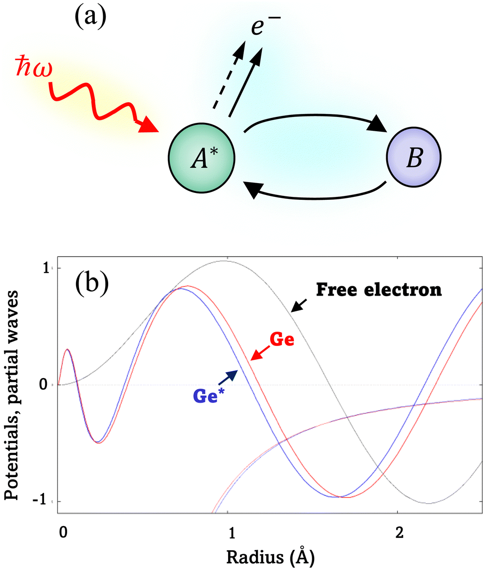 | ||
| Fig. 1 (a) EXAFS: A* is a photon-excited atom that has ejected a photoelectron, and B is a neighboring atom that has backscattered the photoelectron. The incoming photon is represented by its photon energy ħω and the outgoing photoelectron by e−. The total outgoing-electron wave is represented as the original wave (dashed line) plus an additional part (solid line) resulting from the scattering process. (b) Partial waves for the l = 1 channel for a free electron (black), an electron scattered by a neutral Ge atom (red), and an electron scattered by a core-excited Ge atom (blue). Density-functional theory (DFT) atomic potentials are also shown. The relative differences of the potentials are barely discernible on this scale. The extra radial nodes for a 4p-like state are visible within the first 0.5 Å of the absorber, as are the phase shifts in the atom and core-excited atom. All partial waves are normalized consistently. We assumed excitation energy E − E0 = 30 eV. | ||
More than one backscatterer can contribute to χ(k) even if only single-scattering events (prior to the absorber's scattering) are considered. For the i th coordination shell of Ni scatterers, fi(k) denotes its backscattering amplitude, and the scatterer is at a distance Ri from the absorber. The relative phase shift between the original and scattered photoelectron waves is 2kRi + ψi(k). The first term is a “structural” contribution, whereas the second term is an “atomic” contribution that includes phase shifts because of scattering from both the backscatterer and the central absorbing atom. Also relevant are the energy-dependent inelastic mean free path λ(k), spherical wave factors of the form (kRi2)−1, temperature-dependent Debye–Waller effects characterized by mean-square variations in distances σi2, and the many-body amplitude reduction factor S02. The EXAFS signal is therefore modeled using the “EXAFS equation,”
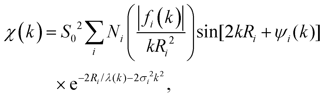 | (3) |
Because the atomic contribution to the phase shift, ψi(k), is accrued as the scattered electron traverses the closed loop between the absorber and scatterer, to a zeroth approximation it should be the same for groups of isoelectronic absorber–scatterer atom pairs in the Periodic Table. This situation may be understood by the one-dimensional scattering diagram in Fig. 1(b) that shows the change in phase of an electron that has been scattered by either a neutral Ge atom or a photoionized Ge atom placed at the origin. The phase shift is the same for incoming and outgoing waves. Angular integration of the photoemission over 4π steradians and many-body effects break this symmetry, however, and the atomic phase shift must be written absorber and scatterer specific:14
 | (4) |
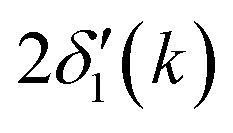 is twice the l = 1 partial-wave phase shift of the ionized absorber (the prime denotes that it is photoionized while channels other than l = 1 would be relevant for edges other than K), and ϕi(k) is the phase shift associated with the scatterer, defined as fi(k) = |fi(k)|exp[iϕi(k)]. (An analogous factor of 2 occurs within ϕi(k).) In principle, fi(k) involves phase shifts in all angular momentum channels.
As discussed by Teo and Lee,15 both the absorber and backscatterer phase shifts vary systematically with atomic number across rows and down columns of the Periodic Table. Peaks and valleys in the backscattering amplitude occur at low photon energies because of various atomic resonances. These resonances are analogous to the Ramsauer–Townsend effect in noble gases, and they are reflected by abrupt jumps by π radians in the backscattering-atom phase shift.16 For the isoelectronic series, these changes in phase occur between approximately 15 eV and 60 eV above the edge, and their effect is the reduced amplitude of the fine-structure oscillations in this energy range (that is observed, for example, in crystalline Ge vs. crystalline Si9,10).
The central atom's phase shift decreases monotonically with k and is independent of the backscattering atom. It is therefore primarily the backscattering atom's phase shift and amplitude functions that give EXAFS its unique ability to identify backscattering atoms and hence “fingerprint” local atomic geometry. As an example, Fig. 2 compares NEXAFS spectra for crystalline Si, crystalline Ge, and two dilute crystalline Ge–Si alloys (Si in Ge and Ge in Si) obtained at both the Si K edge and the Ge K edge, as indicated.9,10 The Si and Ge K edges occur at 1839 eV and 11103 eV, with natural core hole widths of 0.48 eV and 1.96 eV, respectively.17,18 Other than effects of the disparity in core–hole widths, differences between the spectra uniquely identify the backscattering environment as being either predominantly Ge or predominantly Si.
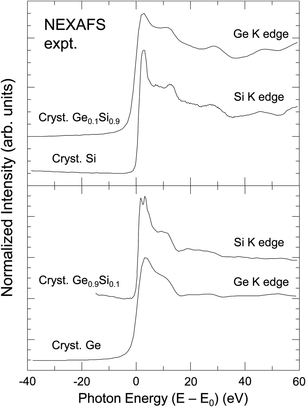 | ||
| Fig. 2 Sensitivity of XAFS to backscattering environment. Top: Si K edge of crystalline Si and Ge K edge of a dilute Ge in Si crystalline Ge0.1Si0.9 alloy. Bottom: Ge K edge of crystalline Ge and Si K edge of a dilute Si in Ge crystalline Ge0.9Si0.1 alloy. The splitting of the white line (or “rabbit ears”) observed at the Si K edge is a density of states effect (see text). (After Woicik and Pianetta.10) | ||
The sharp “rabbit ear” features in the Si K-edge spectrum in dilute crystalline Ge0.9Si0.1 are also noteworthy. A hint of these features is seen in the Si K-edge spectra from pure crystalline Si. These features were first discovered by Woicik et al.19 and attributed to the splitting of the unoccupied conduction band density of states of the Si and Ge crystalline band structures as calculated by Chelikowsky et al.20 The crystalline Si NEXAFS spectrum has since been calculated by Shirley et al.;21 it has also been re-measured by Karlin et al.22 with a photon–energy acceptance width smaller than the natural Si 1s core hole in a unique measurement utilizing a mismatched InSb/KDP high-resolution monochromator crystal pair. The Si K edge of a dilute Si impurity in a Ge host provided a better view of the Ge crystal through the eyes of the Si core, which, figuratively speaking, has an enhanced visual acuity because of its longer core–hole lifetime. These and the NEXAFS spectra from the isoelectronic series will be discussed further below.
4 NEXAFS calculations
NEXAFS calculations were performed in a well-established, two-step manner that is used by several practitioners. In the first step, which is really a preliminary step, we performed self-consistent density-functional-theory (DFT) calculations to have a description of the ground-state electronic structure of a system. This was done within a plane-wave pseudopotential framework utilizing the local-density approximation (LDA).23–26 We used hard norm-conserving pseudopotentials of the Hamann–Schlüter–Chiang type27 with Vanderbilt cut-off functions.28 We used a Ne-like core for the Si pseudopotential, an Ar-like core for the Cu and Zn pseudopotentials, and a Cu+-like core for the Ga, Ge, As, Se, and Br pseudopotentials. (Ordinarily, the strong spatial overlap between 3s, 3p, and 3d Cu states would motivate use of a Ne-like core for Cu, if not Zn. However, a Ne-like pseudopotential was found to adversely affect the band structure near the conduction-band minimum.) We used a 64 Rydberg plane-wave cutoff for the Bloch states in most systems, but a 100 Ry cutoff in CuBr and ZnSe. Fourier transform of the pseudopotentials and their non-local projectors supported these cut-offs. Further details of the methodology for the calculations are described elsewhere.29 While we used a conventional plane-wave/pseudopotential framework, we used a code that we maintain, having compared results with those of other codes on multiple occasions.Regarding atomic coordinates, we used experimental lattice constants for the isoelectronic series and crystalline Si. However, for the Ge0.9Si0.1 alloy, we used an eight-atom cubic unit cell with one Si atom and seven Ge atoms. This choice was close to the target stoichiometry. The cube-side length was interpolated according to Vegard's law. The Si atom was at the cube corner, 3 Ge atoms were at the face centers, and the other 4 Ge atoms were placed symmetrically around the Si with a Si–Ge bond length of 2.386 Å. For the Ge0.1Si0.9 alloy, an analogous cell was used, with a Si–Ge bond length of 2.382 Å. These Si–Ge bond lengths are close to the natural average of the Si–Si and Ge–Ge bond lengths, with small corrections to account for alloy concentration.30 We also computed spectra for the alloys with analogous unit cells in which all bond lengths were those found in bulk Si and bulk Ge, and these spectra appeared nearly identical to those presented.
In the second step, we carried out BSE calculations using a version of the program OCEAN.31–34 OCEAN is a non-commercial program that can be obtained as described in the references. The BSE calculations were performed with all-electron wave functions reconstructed in a projector-augmented-wave fashion.35 This reconstruction restores the radial nodes in valence and unoccupied states required when studying core excitations, and it is described in detail by Vinson and Shirley.34 We used the scalar-relativistic Koelling–Harmon equation in our all-electron atomic calculations, including when pseudopotentials were generated. However, spin degrees of freedom (necessary in the BSE calculations) were incorporated using a paramagnetic, two-component Pauli formalism.
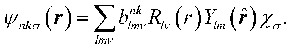
The BSE is an equation of motion for a pair of particles (here, a Bloch electron and core hole) in a many-electron system.36 In the case of a K edge, a basis function for the wave function can be denoted by
 | (5) |
 and a†nkσ create a core hole and Bloch electron, respectively. The ground state is denoted by |0〉. While it may appear peculiar to refer to a crystal momentum for a core hole, it is mathematically convenient to use the fact that a localized state is a superposition of Bloch sums of states like itself. Such Bloch sums are even more pertinent in diffraction anomalous fine structure (DAFS)37 and non-resonant inelastic X-ray scattering (NRIXS),38 which can involve coherent superpositions of stationary states, each with a localized core hole.
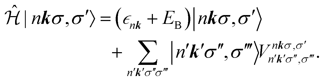
The BSE can be mapped onto a two-particle eigenvalue problem with an effective Hamiltonian described by
 | (6) |
 as an input parameter. For the Ge–Si alloys, we assumed a Vegard's-law-like interpolation scheme to estimate
  . The direct part is attractive and moves oscillator strength in spectra to lower energies, which sometimes leads to discrete bound states. The electron–core hole interaction also includes a repulsive exchange part, which is also described in detail by Vinson and Shirley.34
We included four occupied bands and 91 unoccupied bands in Si, Ge, and GaAs (all of which had two atoms per unit cell). We included sixteen occupied bands and 279 unoccupied bands in the alloys (because of larger unit cells). We included nine occupied bands and 82 unoccupied bands in ZnSe and CuBr, with the five additional occupied bands being because of the filled Zn and Cu 3d states. The energy scale of the bands was enhanced by 5%, which captures most of the many-body correction to the LDA bands (with only the unoccupied bands being of primary interest).
The Brillouin zones were sampled on regular grids up to 16 × 16 × 16 for two-atom unit cells and up to 10 × 10 × 10 for eight-atom unit cells. The grids were offset to accelerate convergence. Spectra differed imperceptibly between the highest two grid densities in all cases. Therefore, the calculations are effectively equivalent to results that would be obtained from an infinitely large cluster in a real-space multiple-scattering framework. Moreover, our results show that spectra would be minimally affected by cluster termination in a real-space multiple-scattering calculation farther than about 6 nm from the central site. The BSE calculations were performed in reciprocal-space, so there were no bona fide supercells. However, the Brillouin-zone sampling means that our calculations correspond to ones using de facto supercells with Born-von Karman boundary conditions: an fcc lattice with primitive lattice-vector length 6.4 nm in two-atom unit cell cases, and a cubic lattice with minimum primitive-lattice vector length 5.6 nm for eight-atom unit cell cases. This establishes the minimum distance between the core-excited site and fictitious replicas of itself that are artifacts of periodicity.
Spectra were calculated in practice using a final-state rule, in which all bands, occupied and unoccupied, were included in the sum over n, but only portions of the spectra above the band gap were retained. This is highly analogous to other methods such as the excited-core hole (XCH)41,42 approach and what is implicitly done in programs such as FEFF. Omitting the occupied bands neglects level-repulsion effects because of the core hole potential that can be important in metals and systems such as those studied here.
Calculated spectra included lifetime damping with three constituents. One constituent was the experimental photon resolution. Another constituent was the natural core–hole width, as reported by Krause and Oliver17 or Campbell and Papp.18 The remaining constituent was the energy-dependent lifetime damping of the Bloch states. We estimated this latter damping using a model dielectric function and electron self-energy that rely on knowledge of sum rules and the one-electron density matrix in each system.43 For the alloys, we used lifetime damping of states in a pure crystal of the majority constituent.
The near-edge spectrum is related to a contribution to the imaginary part of the dielectric function. A contribution is made by each core shell on each site in the unit cell. For one K shell (on one site), one has
 | (7) |
 | (8) |
 | (9) |
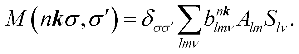
 within the space of pair states after dipole matrix elements of the form M (nkσ,σ′) = 〈0|ê·r|nkσ,σ′〉 have been found. The evaluation can be done using the Haydock recursion method, such as is described in an analogous context by Benedict and Shirley.44
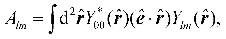
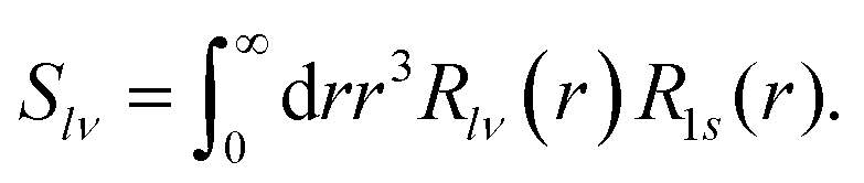
Regarding matrix elements, orthogonality ensures that a dipole matrix element is independent of the location of an atomic site. For convenience and without loss of generality, however, we now suppose that a core hole's site is located at the origin. A core-level wave function has the form
 | (10) |
 | (11) |
 | (12) |
 | (13) |
 | (14) |
 :
: | (15) |
5 EXAFS phase-shift analysis
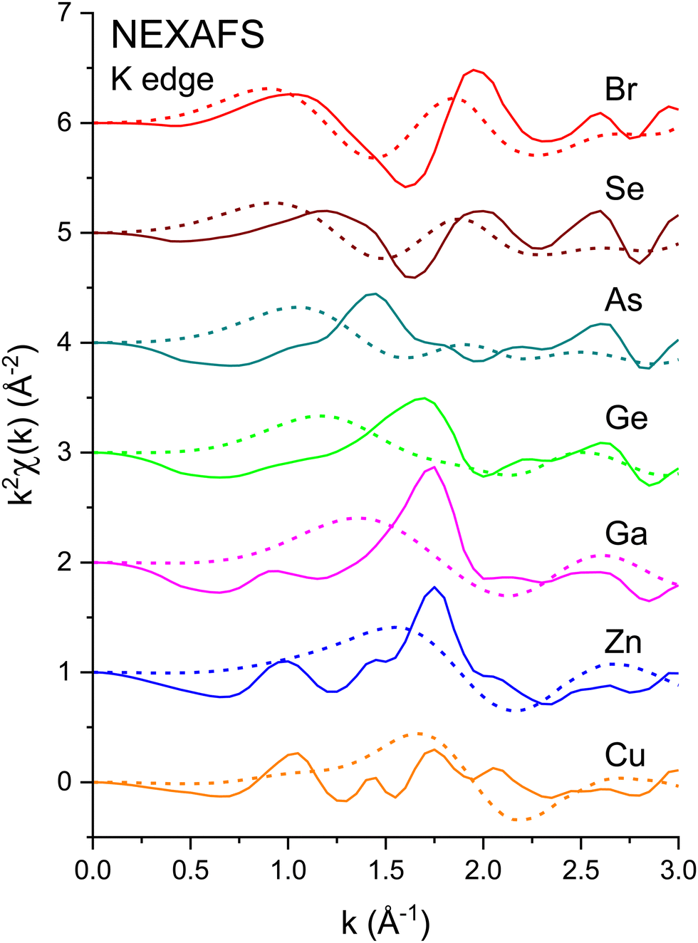
Fig. 3 shows the k2-weighted EXAFS, k2χ(k), measured at the Cu K edge (8979 eV), the Zn K edge (9659 eV), the Ga K edge (10![[thin space (1/6-em)]](https://www.rsc.org/images/entities/char_2009.gif) 367 eV), the Ge K edge (11103 eV), the As K edge (11867 eV), the Se K edge (12658 eV), and the Br K edge (13474 eV) for the crystalline I–VII, II–VI, III–V, and group-IV isoelectronic series. EXAFS was extracted from the normalized μ(k) curves following standard EXAFS procedures.45E0, the energy offset that defines the photoelectron k-vector zero in eqn (2), was taken as the energy of the maximum of the first derivative of the edge jump, which was within 1 eV of the energy position of the edge-jump midpoint. Each spectrum sports the characteristic EXAFS oscillations of a crystalline material, but the higher frequency oscillations of the Cu and Br spectra are quickly damped with increasing k compared to the rest of the series. Note the general similarities of structure; the fact that the feature near 5.2 Å−1 appears in all spectra indicates that it is not a multiple-electron excitation as recently suggested.46
367 eV), the Ge K edge (11103 eV), the As K edge (11867 eV), the Se K edge (12658 eV), and the Br K edge (13474 eV) for the crystalline I–VII, II–VI, III–V, and group-IV isoelectronic series. EXAFS was extracted from the normalized μ(k) curves following standard EXAFS procedures.45E0, the energy offset that defines the photoelectron k-vector zero in eqn (2), was taken as the energy of the maximum of the first derivative of the edge jump, which was within 1 eV of the energy position of the edge-jump midpoint. Each spectrum sports the characteristic EXAFS oscillations of a crystalline material, but the higher frequency oscillations of the Cu and Br spectra are quickly damped with increasing k compared to the rest of the series. Note the general similarities of structure; the fact that the feature near 5.2 Å−1 appears in all spectra indicates that it is not a multiple-electron excitation as recently suggested.46
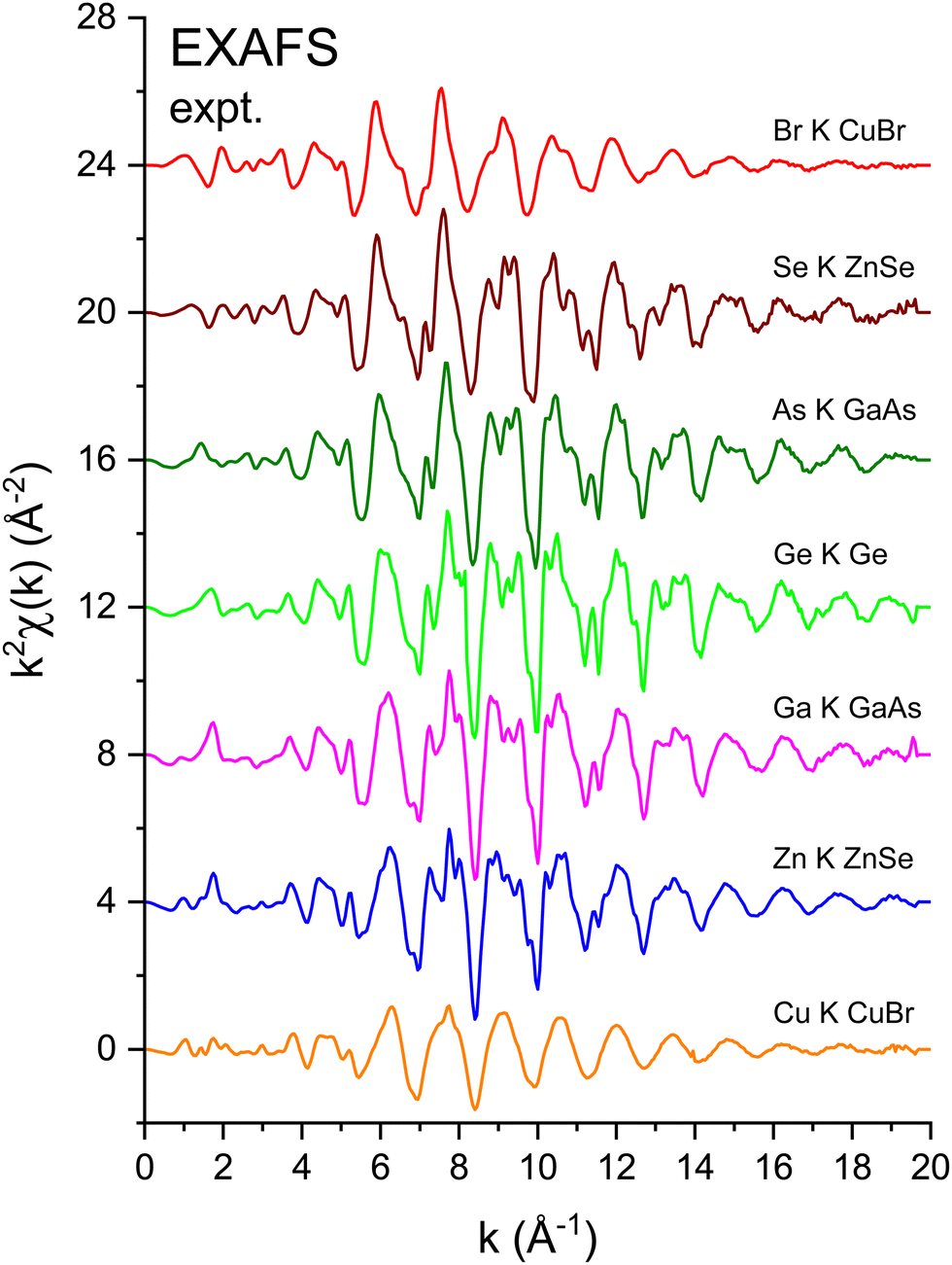 | ||
| Fig. 3 k 2-Weighted EXAFS, k2χ(k), for crystalline CuBr, ZnSe, GaAs, and Ge recorded at the Cu, Zn, Ga, Ge, As, Se, and Br K edges. All data were recorded at LN2 temperature. The zero of the k axis was defined as the maximum of the first derivative of the edge jump (see text). | ||
Both the diamond (C, Si, and Ge) and zinc blende (CuBr, ZnSe, and GaAs) crystal structures consist of two interpenetrating fcc sublattices with one displaced by  along the [111] direction, resulting in tetrahedral bonding around every atom.47 In the homopolar diamond structure, the same element occupies both fcc sublattices, whereas in the heteropolar zinc blende structure, cations occupy one fcc sublattice, and anions occupy the other, as shown in Fig. 4. Thus, in the zinc blende structure, both first- and third-shell single-scattering paths are heteropolar, being either cation–anion or anion–cation, whereas second-shell single-scattering paths are homopolar, being either cation–cation or anion–anion, depending on the edge. The Ge–Si alloy, on the other hand, is technically heteropolar, but it differs from the zinc blende structure in that it is a true binary alloy system; the Si and Ge atoms randomly occupy both fcc sublattices. (For this reason, the zinc blende semiconductors are often referred to as pseudo-binary alloys.)
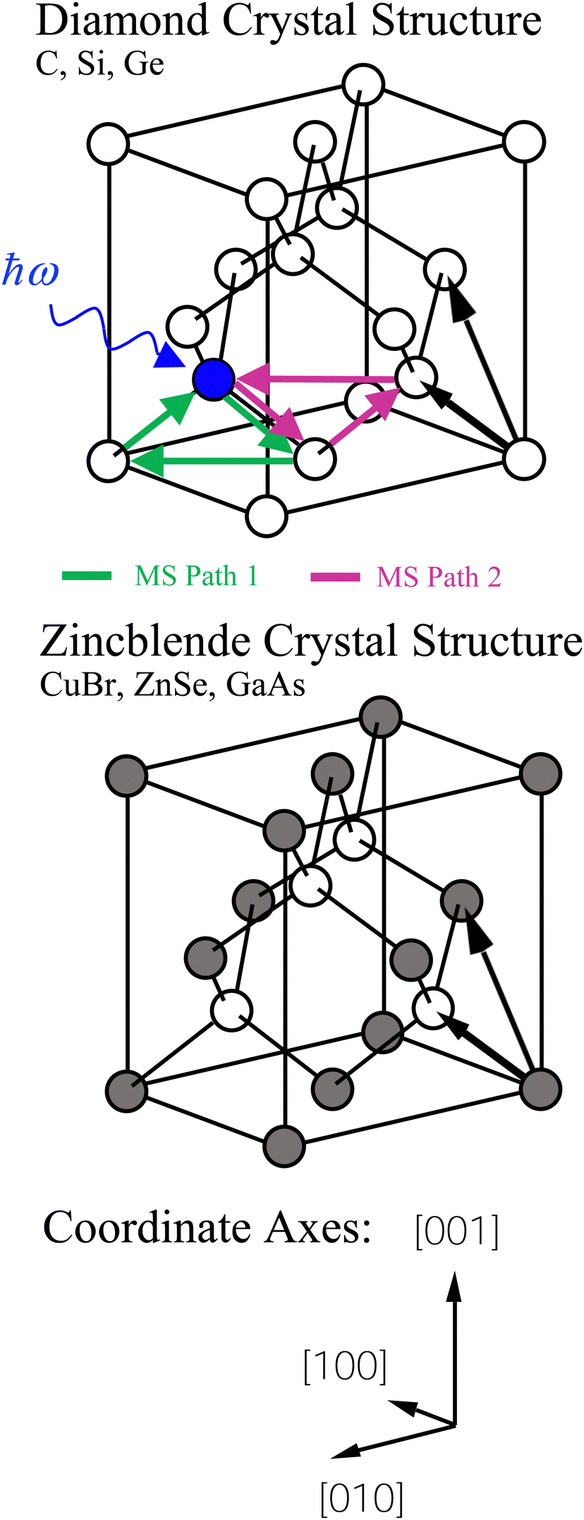 | ||
| Fig. 4 Diamond (C, Si, and Ge) and zinc blende (CuBr, ZnSe, and GaAs) crystal structures. Each are composed of two interpenetrating fcc sublattices displaced by a quarter of a (111) lattice constant along the [111] direction. The cations and anions of the zinc blende structure uniquely occupy separate fcc sublattices as shown. The two most important multiple scattering paths are indicated (see text). | ||
Multiple-scattering pathways also contribute to the EXAFS. The two most important contributions, Path 1 and Path 2, are also indicated in Fig. 4. While Path 1 is contained within the first coordination shell, Path 2 includes an atom in the second shell, although both paths have the same total length. Path 1 contributes less to the EXAFS than Path 2 because Path 1 requires two sharp scattering angles to keep the photoelectron within the first shell.4 The relative contributions to the EXAFS (not including vibrations) may be estimated by the FEFF path analysis shown in Fig. 5, which plots the Fourier transforms of each k2-weighted scattering path. The dominant contributions to the EXAFS are first-, second- and third-shell single scattering for the k range k = 3 Å−1 to 20 Å−1, with relatively small multiple-scattering contributions being as indicated. The first three single-scattering contributions to the EXAFS have little overlap in the R domain for this extended k range, allowing the experimental measurement of their phase and amplitude functions. However, this is not true for the low-k region of the spectra, as shown in Fig. 6, which compares experimental data to its FEFF simulation that includes both single- and multiple-scattering paths within the first four coordination shells (Rmax = 6 Å).48
 | ||
| Fig. 5 FEFF path analysis of the diamond crystal structure for crystalline Ge. Note that the first three single-scattering paths are well resolved in R, and the two multiple scattering paths make only a small contribution to the total scattering for the k range k = 3 Å−1 to 20 Å−1 (see text). | ||
 | ||
| Fig. 6 The XANES or low-k region of the EXAFS shown in Fig. 3 compared to its FEFF simulation for Rmax = 6 Å: Solid line: Experiment. Dashed line: FEFF. Note the high-frequency contributions to the data are not reproduced by the FEFF simulations (see text). | ||
To measure atomic contributions to the phase shifts, the EXAFS data of Fig. 3 were Fourier transformed to the R domain, windowed, and transformed back to the k domain.49Fig. 7 shows the forward transforms, and Fig. 8–10 show the first-, second- and third-shell single-scattering contributions compared to their FEFF simulations.50 Except for the lowest-k region of the figures, excellent agreement is found for both the similarity of phases for cation–anion and anion–cation scattering and the differences of phases for cation–cation and anion–anion scattering. (Note, however, the “aliasing” in the Fourier-filtered experimental second- and third-shell signals at high k, because of their additional damping.)
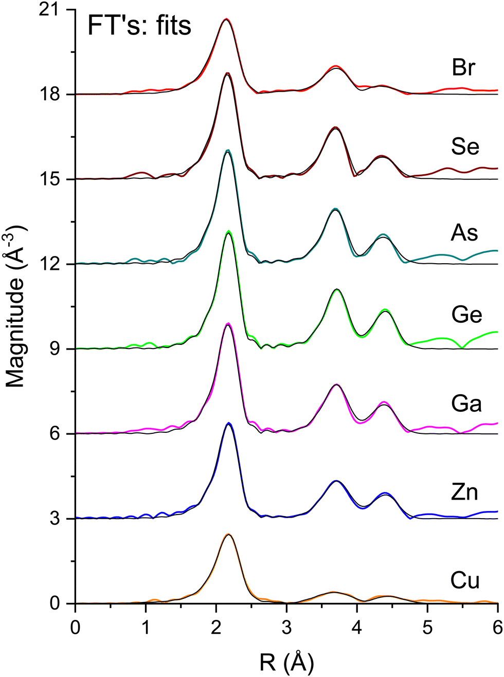 | ||
| Fig. 7 Fourier transforms of the k2-weighted EXAFS shown in Fig. 3 for each absorption edge. The black lines are the best fits to the first three single-scattering paths (see text). | ||
 | ||
| Fig. 8 First-shell, single-scattering contributions to the EXAFS shown in Fig. 3 compared to their FEFF simulations. The FEFF simulations include σ2, but not S02 or E0 corrections (see text). | ||
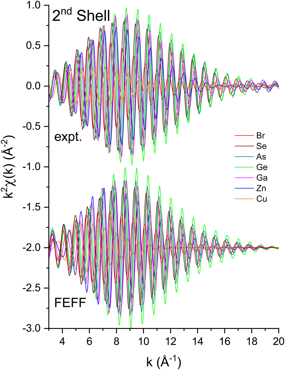 | ||
| Fig. 9 Second-shell, single-scattering contributions to the EXAFS shown in Fig. 3 compared to their FEFF simulations. The FEFF simulations include σ2, but not S02 or E0 corrections (see text). | ||
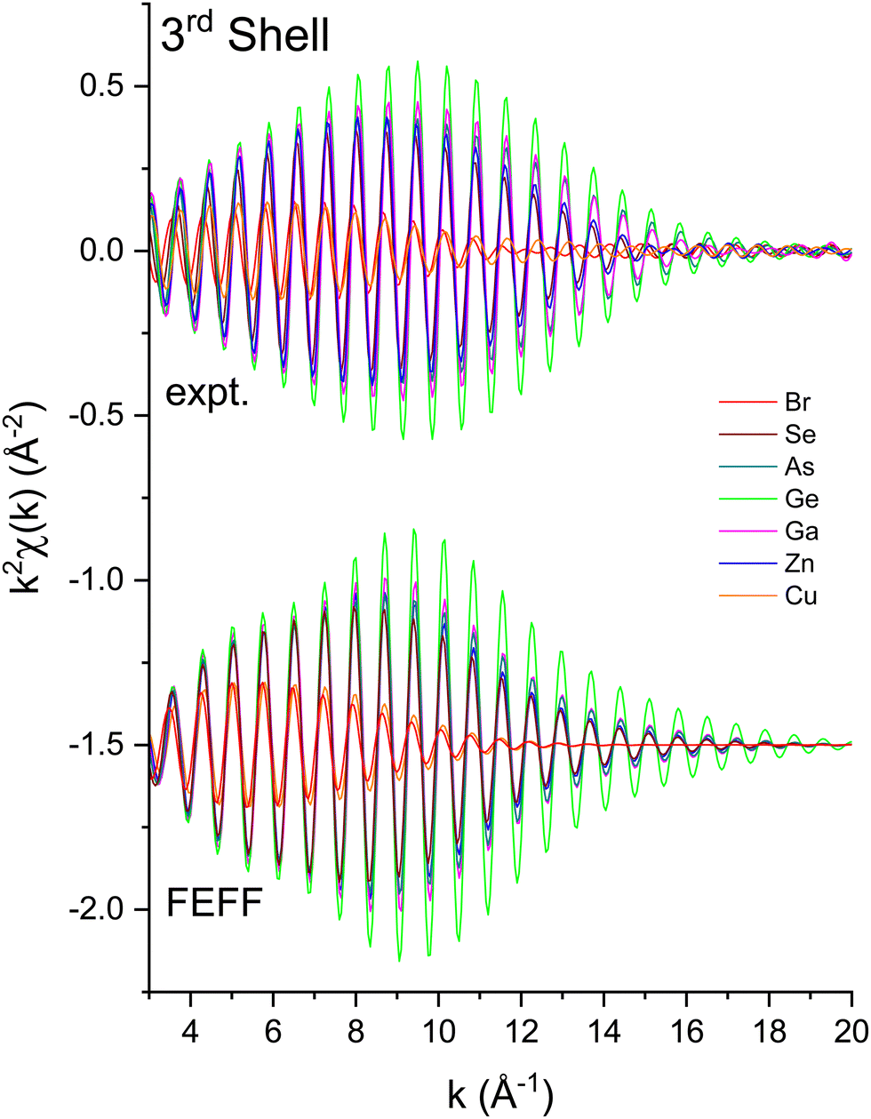 | ||
| Fig. 10 Third-shell, single-scattering contributions to the EXAFS shown in Fig. 3 compared to their FEFF simulations. The FEFF simulations include σ2, but not S02 or E0 corrections (see text). | ||
We next deduced atomic contributions for each path from the complex back-transformed data. For each shell, Fig. 11 and 12 show measured atomic contributions to phase shifts, ψexpt(k), and theoretical ones, ψtheory(k). The first- and third-shell contributions are all similar, but the second-shell contribution increases monotonically with increasing atomic number of the absorber until it reaches a full π-radians (180°) phase difference between waves originating at the Cu and Br sites, which compares to a 30 eV shift of E0 within this k range.
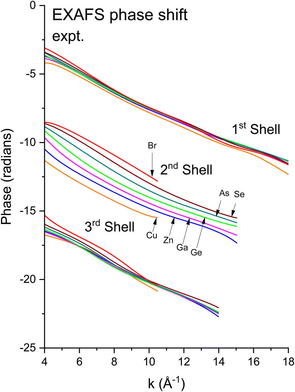 | ||
Fig. 11 Experimental phase functions  corresponding to single scattering from the first, second, and third shells. Each set of phase shifts has been displaced by 2π radians for clarity (see text). corresponding to single scattering from the first, second, and third shells. Each set of phase shifts has been displaced by 2π radians for clarity (see text). | ||
 | ||
Fig. 12 Theoretical FEFF phase functions  corresponding to single scattering from the first, second, and third shells. Each set of phase shifts has been displaced by 2π radians for clarity (see text). corresponding to single scattering from the first, second, and third shells. Each set of phase shifts has been displaced by 2π radians for clarity (see text). | ||
To interpret the behavior of the phase shifts in view of the underlying diamond and zinc blende crystal structures, Fig. 13 illustrates the relevant portion of the Periodic Table. (GaP and AlAs are also shown, because these compounds were used to determine an experimental Ge–Si phase shift in previous work.30) The chemical alchemy of transferring one, two, or three protons between the nuclei of a Ge–Ge homopolar bond respectively creates a heteropolar Ga–As, Zn–Se, or Cu–Br bond. Because EXAFS depends on closed-loop scattering paths as shown in Fig. 1(a), such transfers should have little effect on the total atomic contribution to a phase shift. This is confirmed by Fig. 8–12 for the first- and third-shell single-scattering paths. However, because the second shell of the zinc blende structure always contains either cation–cation or anion–anion neighbors, each second-shell single-scattering path contains a different sum of atomic numbers, and hence the phase shifts vary systematically as observed.
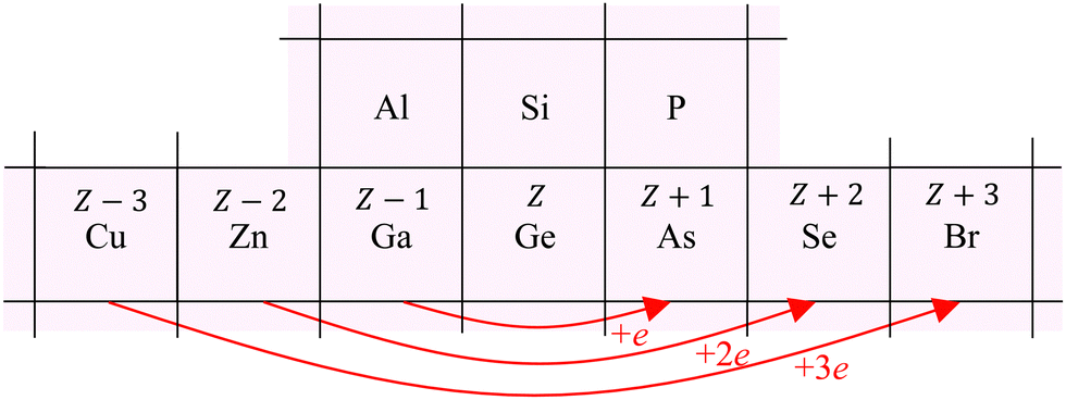 | ||
| Fig. 13 Chemical alchemy and the EXAFS phase shift for the iso-electronic series. The transfer of one proton between the two Ge atoms of a homopolar Ge–Ge bond creates a heteropolar Ga–As bond, the transfer of two protons creates a heteropolar Zn–Se bond, and the transfer of three protons creates a heteropolar Cu–Br bond. First- and third-shell single-scattering EXAFS for the zinc blende structure therefore reflect the same sum of atomic numbers Z along a scattering path, whereas second-shell single-scattering EXAFS reflects a variable sum. Also shown are the group-III and group-V elements compounding AlAs and GaP. These compounds have been used in prior work by Woicik et al.30 to determine the experimental Ge–Si atomic phase shift. | ||
6 Fitting results
The EXAFS data of Fig. 3 were fit according to eqn (3) for the first three coordination shells.51 The FEFF simulations were performed for the ideal, non-vibrating diamond and zinc blende crystal structures using the room temperature lattice constants tabulated in ref. 2 and 3. Negative values of ΔR should therefore be expected for each distance, corresponding to the materials’ thermal contraction at LN2 temperature,52,53 barring anomalous vibrational effects on the EXAFS.54–56Ni for each path was set to its known crystallographic value: N1 = 4, N2 = 12, and N3 = 12. Data for the single homopolar Ge edge were modeled using the 8 fitting parameters: S02, ΔE0, ΔR1, σ12, ΔR2, σ22, ΔR3, and σ32, while data for the two edges of each heteropolar material were co-refined using the 12 fitting parameters: S02 (C), S02 (A), ΔE0 (C), ΔE0 (A), ΔR1, σ12, ΔR2 (C), σ22 (C), ΔR2 (A), σ22 (A), ΔR3, and σ32. Here (C) and (A) denote parameters unique to either a cation or anion edge. (Any term of the form “ΔX” is included in the replacement X → X + ΔX that is implicitly made when computing the theoretical EXAFS, whereas X is the otherwise known or assumed value of a quantity, such as E0 found as described earlier, R1 being the first-neighbor bond length, etc.)Multiple-scattering paths were explicitly neglected in the fits, in part for simplicity, but also for definitiveness, and as already discussed this was deemed acceptable because of the large k range of the collected EXAFS data. Nonetheless, we further tested this approximation for crystalline Ge. Fig. 14 compares the “raw” k2-weighted EXAFS of crystalline Ge to its first 3-shell Fourier filtered contribution. The figure also shows both single-scattering and multiple-scattering fits in k space and the individual single-scattering and multiple-scattering paths considered; this figure is therefore the k-space analogue of Fig. 5, but with the inclusion of the experimentally determined EXAFS Debye–Waller factors. It should be mentioned that even for the extended k range and relative simplicity of the homopolar Ge data, the multiple-scattering paths could not be fit independently, so their path parameters were written as sums of the single-scattering parameters according to ref. 57. Results of the single-scattering and multiple-scattering fits are compared in Fig. 15. Within statistical uncertainties, inclusion of multiple scattering does not improve results for the first three coordination shells.
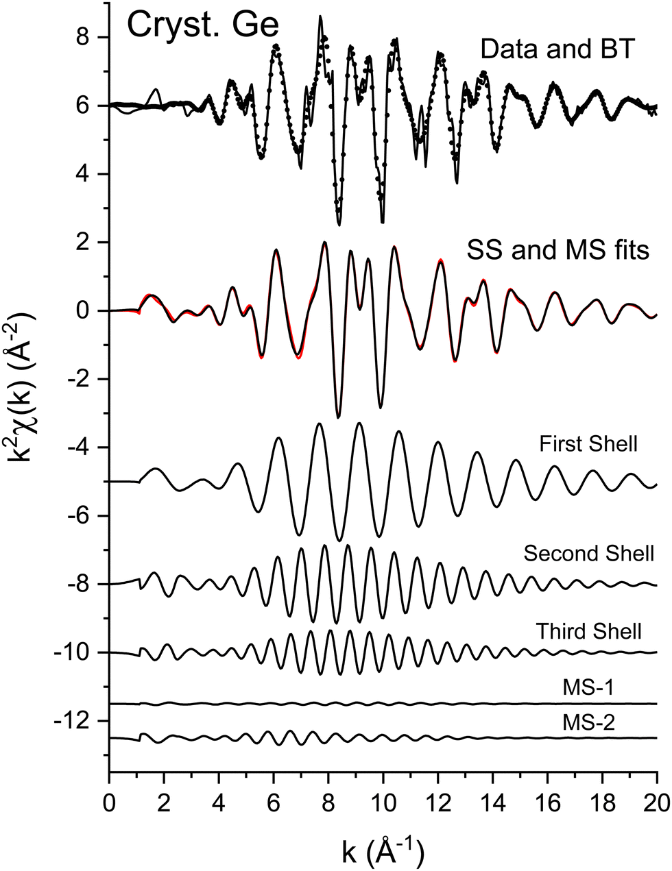 | ||
| Fig. 14 Upper: k2-Weighted EXAFS, k2χ(k), for crystalline Ge (solid line) plotted with its Fourier-filtered first three-shell contribution (dots). Immediately below are single-scattering (black) and multiple-scattering (red) fits to the filtered data. Lower: Individual scattering contributions: first-, second-, and third-shell single-scattering paths and the multiple-scattering paths 1 and 2 (see text). | ||
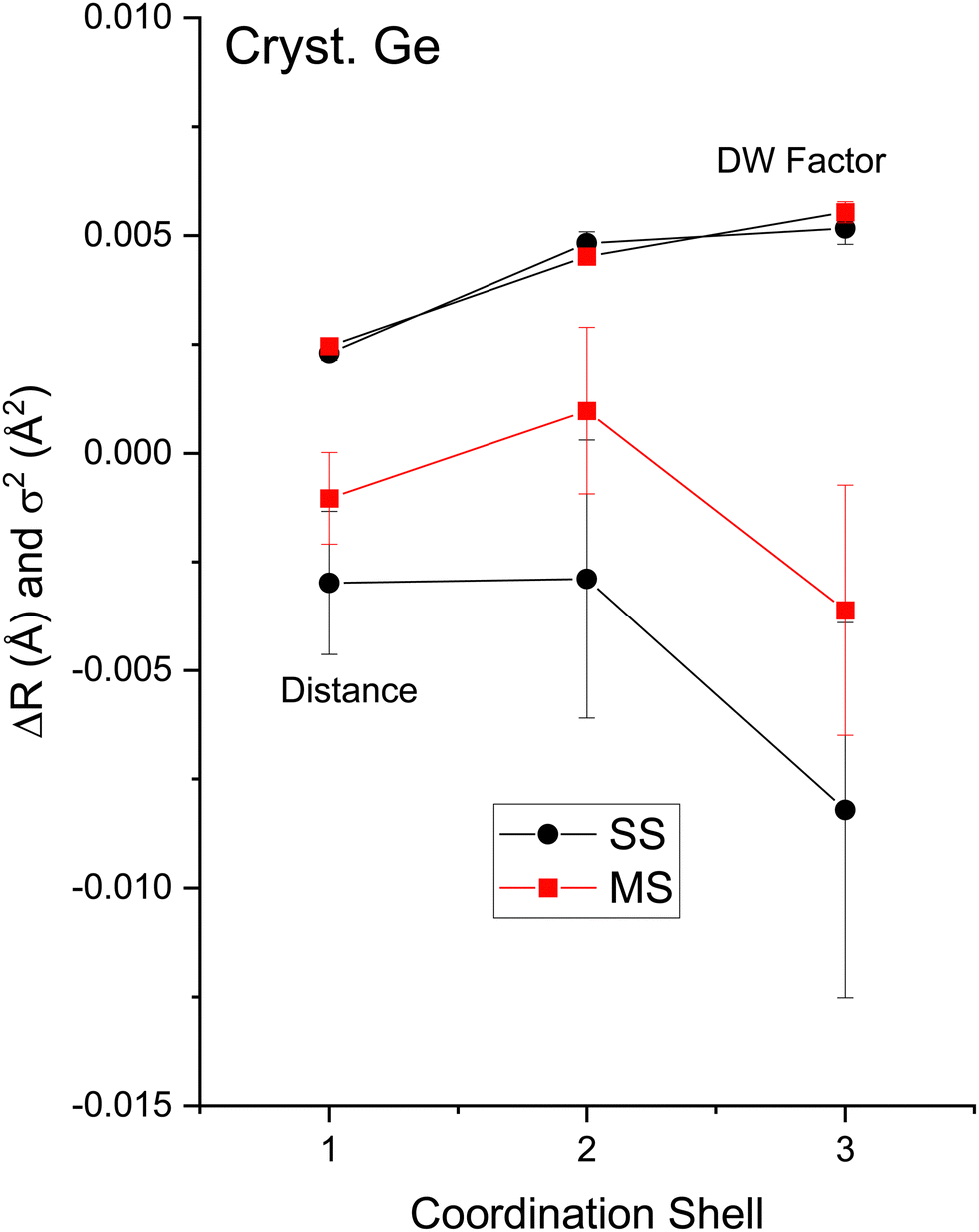 | ||
| Fig. 15 Single-scattering and multiple-scattering EXAFS fit results for crystalline Ge. The figure plots changes in bond lengths ΔR1,2,3 and Debye–Waller factors σ1,2,32 for the first-, second-, and third-coordination shells. Results of single-scattering (black) and multiple-scattering (red) fits are indicated (see text). | ||
Fig. 7 plots the magnitudes of the Fourier transforms of the k2χ(k) data and their single-scattering fits, and Fig. 16–18 summarize fit results that are discussed below.
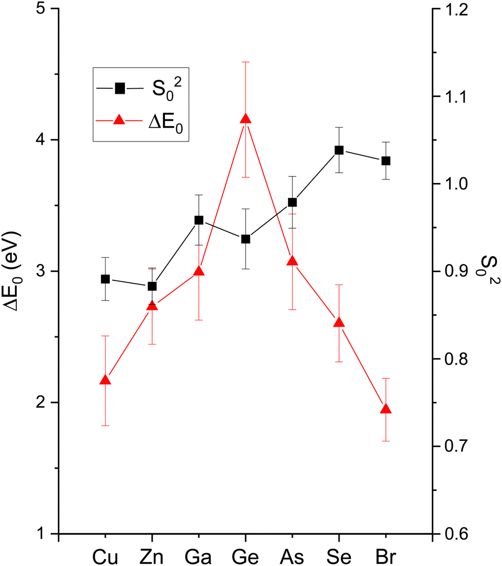 | ||
| Fig. 16 EXAFS fitting results for crystalline CuBr, ZnSe, GaAs, and Ge at the Cu, Zn, Ga, Ge, As, Se, and Br K edges as indicated. Both edges of each heteropolar material were co-refined. The figure plots ΔE0 and S02 (see text). | ||
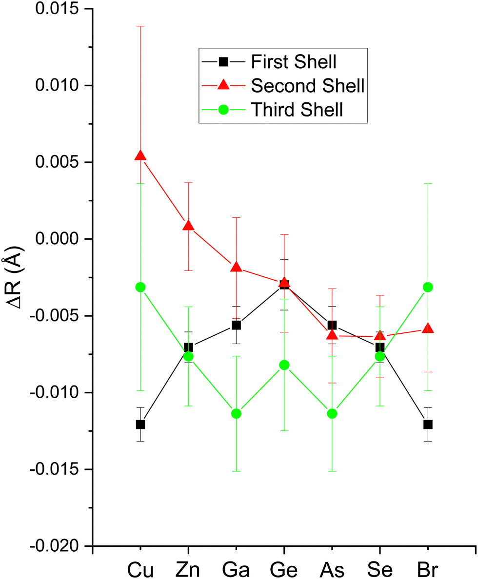 | ||
| Fig. 17 EXAFS fitting results for crystalline CuBr, ZnSe, GaAs, and Ge at the Cu, Zn, Ga, Ge, As, Se, and Br K edges as indicated. Both edges of each heteropolar material were co-refined. The figure plots changes in the first-, second-, and third-shell bond lengths ΔR1,2,3 from their room-temperature values (see text). | ||
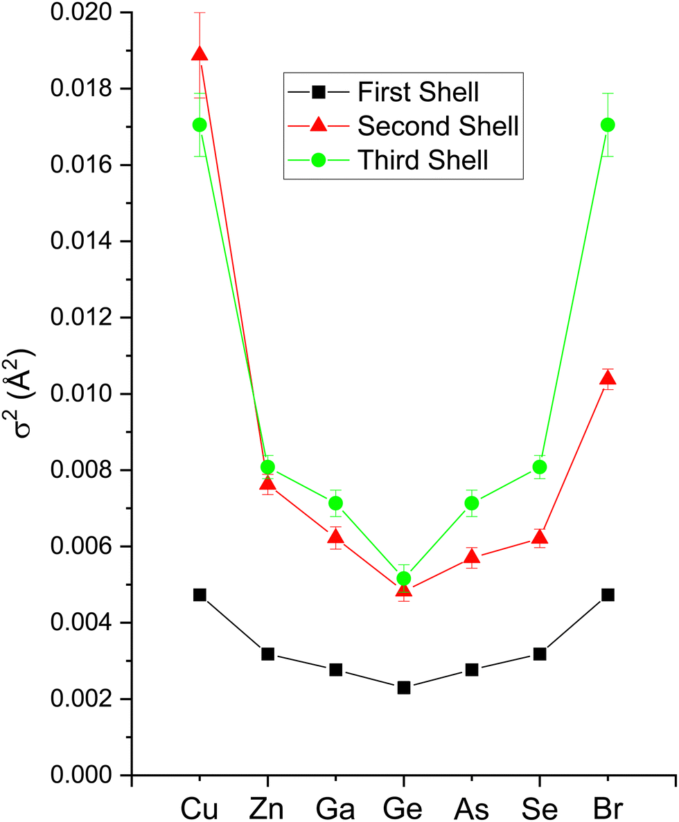 | ||
| Fig. 18 EXAFS fitting results for crystalline CuBr, ZnSe, GaAs, and Ge at the Cu, Zn, Ga, Ge, As, Se, and Br K edges as indicated. Both edges of each heteropolar material were co-refined. The figure plots Debye–Waller factors σ1,2,32 for the first, second, and third coordination shells (see text). | ||
The amplitude reduction factor S02 increases with atomic number going from Cu to Br. This finding is consistent with the ansatz suggested by Stern et al.2,3 that the amount of charge transfer following excitation of the core hole would be larger for the cation than for the anion of a heteropolar material (note that the relative changes in S02 between the anion and cation also scale with ionicity). Both ΔE0 (C) and ΔE0 (A) decrease simultaneously with increasing ionicity, as does the cation–anion (or anion–cation) bond length ΔR1. Having a greater amount of disorder in each material further emphasizes this trend, as noted by the Debye–Waller factor σ12 that increases with increasing ionicity.
The second-shell cation–cation distribution σ22 (C) is always greater than its second-shell anion–anion distribution σ22 (A). In fact, CuBr σ22 (C) exceeds its σ22 (A) by nearly a factor of two; it also exceeds its third-shell distribution σ32, breaking the general rule of such disorder increasing monotonically with distance.58 We note that a negative ΔR2 (C) was never found for the Cu–Cu second-neighbor distance in CuBr, despite data being collected at liquid–nitrogen temperature. (We also tested models with separate ΔE0's for the first and second shells in addition to including the multiple-scattering paths MS-1 and MS-2 in the fits.) In fact, ΔR2 (C) > ΔR2 (A) for all zinc blende materials studied, and this trend is also emphasized by the amount of disorder present. Consequently, the observed bond lengths and distances may reflect large second-shell cation–cation displacements and anharmonic first-shell cation–anion (or anion–cation) displacements in the most ionic of these materials.55,57,59–63
Despite these apparent anomalies, it appears that a proper FEFF analysis of high-quality, low-temperature and high-k EXAFS data can produce bond lengths with uncertainties as small as ΔR1 = ±0.005 Å, ΔR2 = ±0.01 Å, and ΔR3 = ±0.01 Å.
Having explored the Z-dependence of the atomic phase shifts, we now turn to errors that may result if individual scattering paths are not properly identified in an EXAFS fitting model. Fig. 19 shows fit results for both the second-shell cation–cation ΔR2 (C) and anion–anion ΔR2 (A) distances for the heteropolar compounds using the second-shell phase and amplitude functions for crystalline Ge. For crystalline Ge itself, its second-shell distance ΔR2 was fit using its first-shell phase and amplitude functions. Clearly, including the wrong backscattering atom in an EXAFS model can lead to significant, yet compensated errors in both ΔE0 and ΔRi that still produce a good fit. On the other hand, there are no discernable differences between the fits for the second shell of crystalline Ge using either its first- or second-shell phase and amplitude functions. This analysis therefore establishes the general transferability of phase and amplitude functions between the first- and second-shell EXAFS oscillations for a given structure if the backscattering atom is properly identified. Strict transferability of phase functions between scattering shells is also demonstrated in Fig. 11 and 12 by the equivalence of the first-, second- and third-shell phase functions of crystalline Ge (that have been offset by factors of 2π radians in each plot).
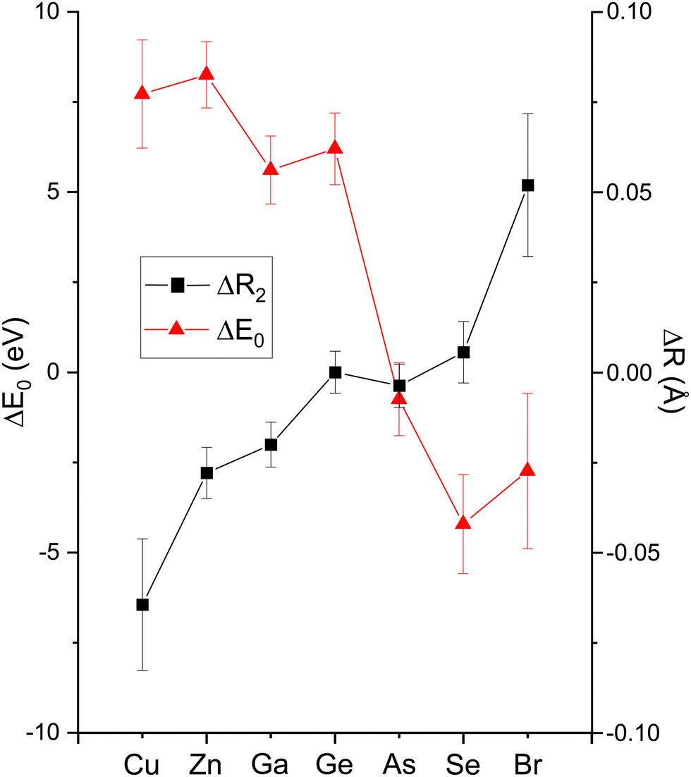 | ||
| Fig. 19 EXAFS fitting results for the second shells of crystalline CuBr, ZnSe, GaAs, and Ge recorded at the Cu, Zn, Ga, Ge, As, Se, and Br K edges as indicated. The figure plots both ΔR2 and ΔE0. For the heteropolar materials, the fits were performed using the FEFF calculation of the second-shell scattering for crystalline Ge. For Ge itself, the FEFF calculation of the first-shell Ge scattering was used to fit the Ge second shell (see text). | ||
7 NEXAFS results
The EXAFS signal and NEXAFS spectral features are both aspects of the absorption spectrum. The EXAFS equation isolates interference between the primary outgoing photoelectron wave and backscattered contributions thereto, but not terms that are second order in the latter. In contrast, NEXAFS usually considers the entire Δμ(E). Furthermore, when interpreting NEXAFS it is important to remember that the photoelectron effective mean free path reflects both photoelectron and core–hole lifetime damping. It therefore remains finite even for a long-lived photoelectron final state. It may therefore be possible to interpret salient aspects of NEXAFS structure using a small number of coordination shells, and a full multiple-scattering description of NEXAFS could, in principle, converge even for energies close to an edge.13 Nonetheless, the low-energy behavior of scattering amplitudes can be complicated. In addition, the low kinetic energy of the photoelectron can necessitate a more complete solution of the one-electron wave equation, including non-spherical contributions to atomic potentials and variations in the potential experienced by an electron in interstitial regions, because these effects may not be small compared to an electron's kinetic energy. For these reasons, it can be expedient to use band-structure-based methods, such as our BSE approach, to treat near-edge spectral features, because these methods include the electron wave functions and the potentials they experience in full detail.Fig. 20(a) shows the experimental K-edge NEXAFS for CuBr, ZnSe, GaAs, and Ge. A material specific, sharp, structured rise at threshold, followed by the near-edge fine-structure modulations appears in all spectra. The fine structure is absent in the spectrum from amorphous Ge that has been plotted atop its crystalline spectrum, consistent with the absence of long-range order in the amorphous lattice.64
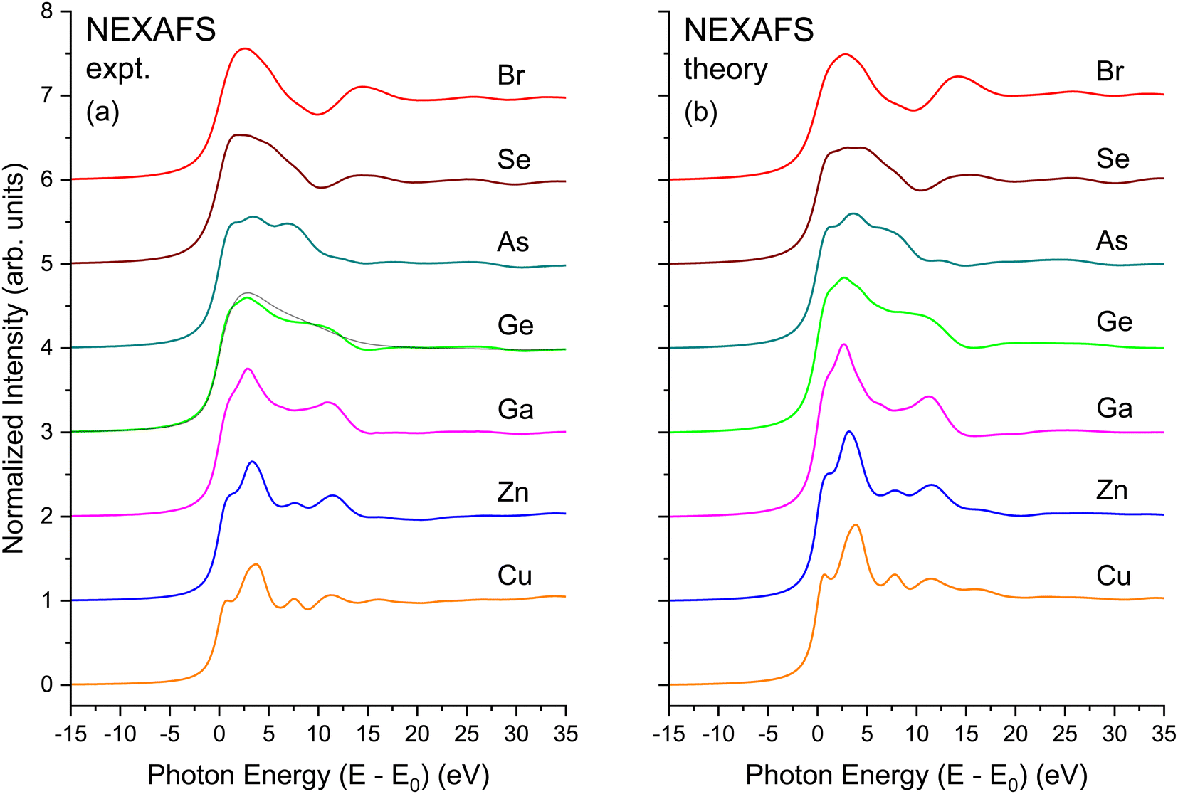 | ||
| Fig. 20 NEXAFS spectra for crystalline CuBr, ZnSe, GaAs, and Ge recorded at the Cu, Zn, Ga, Ge, As, Se, and Br K edges as indicated. (a) Experiment. (b) BSE theory. The black line in (a) overplotting the crystalline Ge data are data from amorphous Ge (see text). | ||
Fig. 20(b) shows results of BSE calculations for each crystalline edge. In all cases, comparison with the data of Fig. 20(a) is quite satisfactory in terms of reproducing features, with only minor differences in relative oscillator strengths and energies of the primary features and the signature edge. Important to point out is that this agreement has been achieved with no adjustable parameters. The fact that the calculations so closely reproduce the measured spectra speaks favorably about the validity of the customary DFT-plus-BSE approach used here.
Fig. 21 shows the matrix-element weighted l = 1 PDOS (l = 1 alone, because we are considering K-edge dipole excitations) for each material. Along with each PDOS we also plot the non-interacting NEXAFS spectra that include the lifetime effects but not the electron–core hole interaction. Each PDOS consists of two lobes within approximately 5 eV of the conduction-band minimum (approximately equal to E0) that closely follow even very early band-structure calculations for the diamond and zinc blende semiconductors.20 These features arise from critical points associated with the first four conduction bands of the crystalline band structure, and they most strongly contribute to the shape of the edge in the immediate vicinity of its peak. The PDOS also reveal significant higher-energy structures that arise from higher-lying conduction bands.
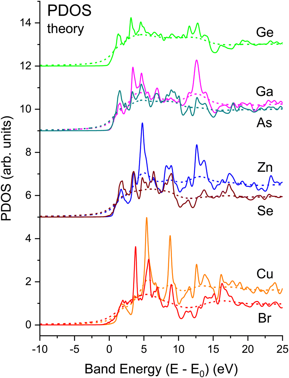 | ||
| Fig. 21 Matrix element weighted l = 1 partial density of states (PDOS) for crystalline CuBr, ZnSe, GaAs, and Ge calculated by density functional theory (DFT) (solid lines) compared to electron self-energy damped spectra (dashed lines). Neither include the electron core hole interaction, i.e., they are “non-interacting” spectra. Both the cation and anion spectra have been normalized by the same factor; they reflect both the larger matrix element and the larger unoccupied state density for the cation in each case (see text). | ||
Strong correlations between PDOS features for anions and cations reflect shared unoccupied anti-bonding states. The common features have different intensities on the cation vs. anion sites, which reflects relative energy orderings of atomic levels (e.g., Ga vs. As 4s and 4p) and their solid-state chemical bonding.65 (Obviously, the crystalline environment spreads these and higher energy states into bands.) Slight differences occur between energies of corresponding features, although maxima in the PDOS tend to indicate flat parts of bands.23 The relative weights of these features are heralded in the NEXAFS spectra. For example, a feature is found near 13 eV in both the Ga and As spectra, but it is stronger in the Ga one, while the reverse is true for a feature near 10 eV. Such details of the chemical bonding as measured by NEXAFS are analogous to the energy dependence of the occupied Ga and As PDOS as measured by X-ray standing-wave valence-band photoemission.66 In contrast, similar correlations between cation and anion PDOS are not as pronounced in more ionic compounds, e.g., TiO2,67 which has non-bonding O π states at the valence-band maximum.68
To illustrate the role of the photoelectron–core hole interaction, Fig. 22 compares the non-interacting spectrum for each edge to its full BSE calculation. The onset of each edge exhibits a large amount of excitonic enhancement. It is also clear that the interaction shifts oscillator strength to lower energies, and its inclusion in the BSE is necessary to bring the intensities of the PDOS into overall agreement with experiment. The peak heights decrease with increasing energy in both the non-interacting and interacting spectra, but the decrease is more pronounced in the interacting case, with the net effect being the energy shifts observed. These shifts are analogous to the positive effect on spectra by the central atom phase shift as calculated by Teo and Lee15 for the positively charged Ca2+ ion.
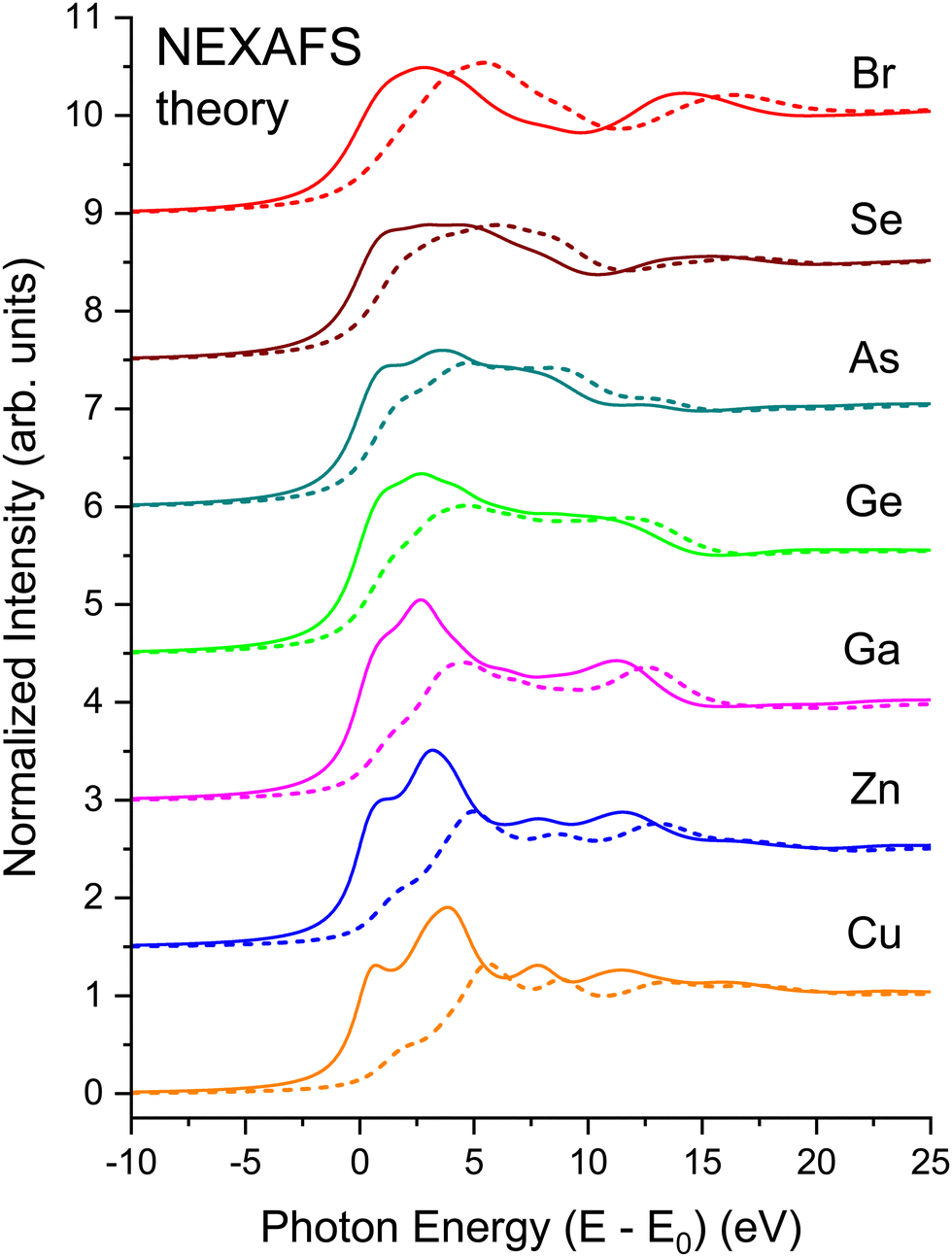 | ||
| Fig. 22 Comparison of interacting BSE (solid lines) and non-interacting (dashed lines) NEXAFS spectra for crystalline CuBr, ZnSe, GaAs, and Ge at the Cu, Zn, Ga, Ge, As, Se, and Br K edges as indicated (see text). The non-interacting spectra do not include the core–hole interaction. | ||
Considerable redistribution of oscillator strength should always be observed because of the core hole, but it is only in the case of a bound exciton that energy shifts are observed.69 Close examination of the eigenstates for CuBr, on the other hand, finds that the shifts associated with the excitonic binding energy are only as small as 0.3 eV, consistent with the large amount of dielectric screening expected in these materials.70 Consequently, the major differences between the interacting and non-interacting spectra may be attributed to core hole-induced changes in the transition-matrix elements and to the effects of the attractive core–hole potential on the central atom phase shift, but not to an exciton binding energy. As previously deduced, these changes can account for nearly all discrepancy between one-electron theories and experiment.44
A partial harmonization of the scattering and band-structure interpretations of NEXAFS also emerges. The phase-shift analysis demonstrates that the different atomic numbers in zinc blende systems produce scattering resonances at different energies for mixed- vs. pure-atom scattering paths.71 These resonances add both constructively and destructively to produce the energy dependence of the fine structure, in analogy to the different energies of the cation and anion 4s and 4p atomic states that contribute to the crystalline band structure as discussed above.
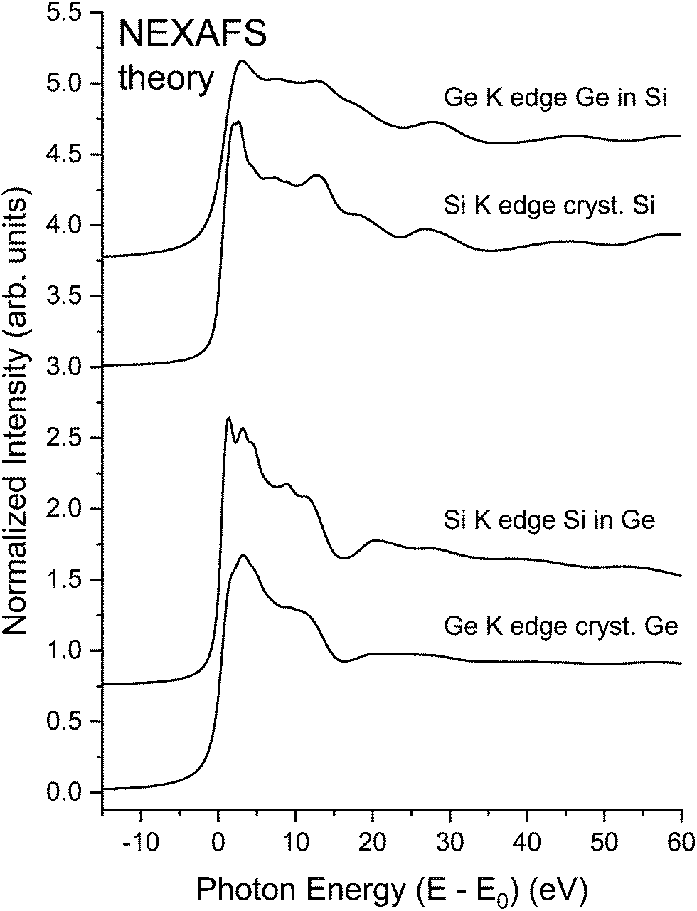
To further demonstrate the utility of our NEXAFS methodology, we consider the NEXAFS for crystalline Si, crystalline Ge, and the two crystalline Ge–Si alloys shown in Fig. 2. Fig. 23 shows the results of BSE calculations, which again compare favorably with experiment. Other than core–hole widths differing, the spectra for each alloy closely resemble spectra of pure samples of their majority constituent, therefore illustrating how the extended backscattering environment (including contributions from long paths) and lifetime widths dominate spectral features.
 | ||
| Fig. 23 Theoretical NEXAFS spectra for crystalline Si, crystalline Ge, a dilute Si impurity in a crystalline Ge host, and a dilute Ge impurity in a crystalline Si host recorded at the Si K edge and the Ge K edge as indicated (see text). | ||
As demonstrated in Fig. 22, excitonic enhancement of the near edge structure for these materials is significant, and it is significantly larger than would be deduced based on a 1/ε2 reduction of the exciton binding energy.19,70 This warrants closer examination of spectra with the higher resolution gained at the Si K edge. The splitting of the “white line” or “rabbit ears” observed in crystalline Si and crystalline Ge–Si alloys has been attributed to the splitting between the first two large density of states features of the crystalline Si and crystalline Ge band structures:19 about 1.1 eV for crystalline Si and 1.8 eV for crystalline Ge.20 (For the dielectric functions of Si and Ge, cf. ref. 72.) Because the band structure of the Ge–Si alloy system closely follows the virtual-crystal approximation (VCA),73 the splitting of these density-of-states features would also follow this trend,19 as displayed by the theoretical Si K-edge NEXAFS spectra shown in Fig. 23. Fig. 24, on the other hand, shows the high-resolution Si near-edge spectrum recorded with the mismatched InSb/KDP monochromator crystal pair22 with its PDOS and higher-resolution (less broadened) BSE calculation. The Si spectrum displays significant excitonic enhancement, and its inclusion is necessary for an accurate description of the NEXAFS.
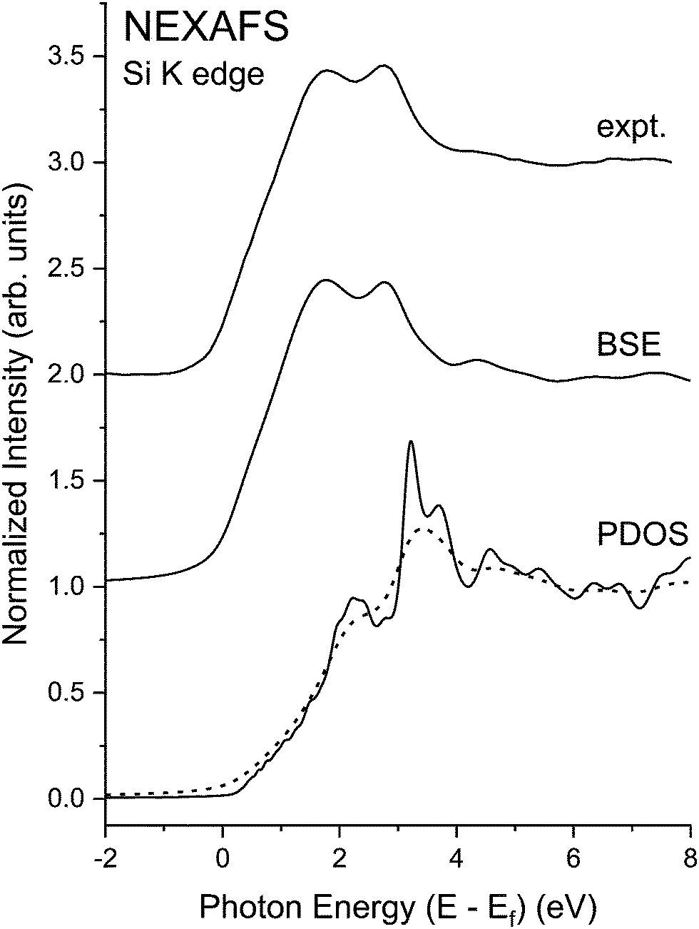 | ||
| Fig. 24 Si K-edge NEXAFS spectra from crystalline Si recorded with the high-resolution InSb/KDP monochromator crystal pair22 compared to its “interacting” BSE spectrum. Also shown are the matrix element weighted l = 1 partial density of states (PDOS) (solid line) calculated by density functional theory (DFT) and the electron self-energy damped “non-interacting” spectrum (dashed line). Note the significant excitonic enhancement of the near-edge features (see text). Ef indicates the Fermi level. | ||
8 Conclusions
We have presented a comprehensive experimental and theoretical study of the K-edge EXAFS and NEXAFS for the isoelectronic series CuBr, ZnSe, GaAs, and Ge. In all cases, the ab initio EXAFS code FEFF accurately predicts the first three EXAFS single-scattering shells, while calculations based on the BSE accurately capture the NEXAFS. Consideration of the NEXAFS of crystalline Si and a series of crystalline Ge–Si alloys demonstrates the power of NEXAFS in determining the local backscattering environment around an absorbing atom. It also emphasizes the importance of the photoelectron–core hole interaction and details of the unoccupied density-of-states in the chemical interpretation of spectra. The importance of the scattering phase shifts over the full spectral energy range has also been demonstrated. It should be clear that NEXAFS has developed to the point where it can be used as an analytical tool for structural determination and for testing the accuracy of theoretical calculations that predict both ground- and excited-state electronic structures.The results shown here can also be compared to those using enhanced multiple-scattering74 and finite-difference-method techniques.75 The latter results appear as efficacious as our BSE approach, to which both papers cited refer. The qualitative improvements in agreement between predicted and observed spectral features are demonstrated here when considering Fig. 20 and 22. This is a typical outcome when including electron core–hole interactions via the BSE. However, the high-energy normalization of the absorption spectra indicates the need to include effects of multiple excitations that transfer oscillator strength upward in energy as noted in Section 7. The cumulant representation of the core–hole Green's function76 has recently been used to incorporate charge-transfer satellites and their associated losses in the X-ray spectra of SrTiO3, MoS2, and TiO2.77,78 This work applied the cumulant to BSE calculations of the NEXAFS via an ex post facto convolution in frequency space, in a manner analogous to how the many-body amplitude reduction factor S02 is included as a multiplicative factor in FEFF simulations and EXAFS modeling. Close examination of Fig. 20(a) and (b) reveals how the edge intensities of the Cu and Br NEXAFS also follow the trend advocated by Stern et al.2,3 concerning S02. In fact, the intensity of all cation NEXAFS displayed is over-represented by theory while the intensity of the corresponding anion NEXAFS is much better described, and these results follow the S02 values determined from the EXAFS fits indicating areas for future improvements.
In conclusion, this work has presented experimental data and a modern theoretical NEXAFS analysis of the seven K edges in the isoelectronic series CuBr, ZnSe, GaAs, and Ge in a uniform manner that may be compared to earlier studies. EXAFS for the same systems has uniquely revealed properties of scattering physics when successive protons are transferred between the nuclei of two sites, beginning with (homopolar) Ge. It has also provided a materials’ comparison that goes further than previous work, being enabled by the greater energy range of present measurements. Similar NEXAFS analysis of Si and crystalline Ge–Si alloys, including treatment of the Si 1s edge probed with unusually high-energy resolution, has also been given.
Author contributions
Both authors contributed to the entire text of the manuscript. E. L. S. performed NEXAFS calculations, and J. C. W. performed all measurements and EXAFS analysis. All figures are original to this work.Conflicts of interest
There are no conflicts to declare.Acknowledgements
This research was performed at the National Institute of Standards and Technology (NIST) beamline BMM of the National Synchrotron Light Source II, a U.S. Department of Energy (DOE) Office of Science User Facility operated for the DOE Office of Science by Brookhaven National Laboratory under Contract No. DE-SC0012704. Preliminary data were collected at the National Synchrotron Light Source and the Advanced Photon Source. Previously published work was performed at the Stanford Synchrotron Radiation Laboratory and the National Synchrotron Light Source. Additional funding was provided by NIST.References
- D. E. Sayers, E. A. Stern and F. W. Lytle, Phys. Rev. Lett., 1971, 27, 1204 CrossRef CAS.
- E. A. Stern, B. A. Bunker and S. M. Heald, Phys. Rev. B: Condens. Matter Mater. Phys., 1980, 21, 5521 CrossRef CAS.
- B. A. Bunker and E. A. Stern, Phys. Rev. B: Condens. Matter Mater. Phys., 1983, 27, 1017 CrossRef CAS.
- A. Bianconi, A. Di Cicco, N. V. Patel, M. Benfatto, A. Marcelli, C. R. Natoli, P. Pianetta and J. C. Woicik, Phys. Rev. B: Condens. Matter Mater. Phys., 1987, 36, 6426 CrossRef CAS PubMed.
- E. A. Stern, Phys. Rev. B: Condens. Matter Mater. Phys., 1974, 10, 3027 CrossRef CAS.
- P. A. Lee and J. B. Pendry, Phys. Rev. B: Condens. Matter Mater. Phys., 1975, 11, 2795 CrossRef CAS.
- J. J. Rehr, J. Mustre de Leon, S. I. Zabinsky and R. C. Albers, J. Am. Chem. Soc., 1991, 113, 5136 CrossRef ; see also https://feff.phys.washington.edu/feffproject-feff-download.html.
- E. L. Shirley, Phys. Rev. Lett., 1998, 80, 794 CrossRef CAS.
- J. C. Woicik, PhD thesis, Stanford University, 1989.
- J. C. Woicik and P. Pianetta, Studies of Si-Ge Interfaces with Surface EXAFS and Photoemission, in Synchrotron Radiation Research: Advances in Surface and Interface Science, ed. R. Z. Bachrach, Springer, Boston, MA, 2015, vol. 2 Search PubMed.
- S. Kraft, J. Stümpel, P. Becker and U. Kuetgens, Rev. Sci. Instrum., 1996, 67, 681 CrossRef CAS.
- B. Ravel and M. Newville, J. Synchrotron Rad., 2005, 12, 537 CrossRef CAS PubMed.
- J. J. Rehr and R. C. Albers, Rev. Mod. Phys., 2000, 72, 621 CrossRef CAS.
- P. A. Lee, P. H. Citrin, P. Eisenberger and B. M. Kincaid, Rev. Mod. Phys., 1981, 53, 769 CrossRef CAS.
- B.-K. Teo and P. A. Lee, J. Am. Chem. Soc., 1979, 101, 2815 CrossRef CAS.
- L. I. Schiff, Quantum Mechanics, McGraw-Hill, New York, 1968 Search PubMed.
- M. O. Krause and J. H. Oliver, J. Phys. Chem. Ref. Data, 1979, 8, 329 CrossRef CAS.
- J. L. Campbell and T. Papp, At. Data Nucl. Data Tables, 2001, 77, 1 CrossRef CAS.
- J. C. Woicik, R. S. List, B. B. Pate and P. Pianetta, Solid State Commun., 1988, 65, 685 CrossRef CAS.
- J. Chelikowsky, D. J. Chadi and M. L. Cohen, Phys. Rev. B: Condens. Matter Mater. Phys., 1973, 8, 2786 CrossRef CAS.
- E. L. Shirley, J. A. Soininen and J. J. Rehr, SPIE Proc., 2004, 5538, 125 CrossRef.
- B. A. Karlin, J. C. Woicik and P. L. Cowan, Nucl. Instrum. Methods Phys. Res., Sect. A, 1994, 347, 360 CrossRef CAS.
- P. Hohenberg and W. Kohn, Phys. Rev., 1964, 136, 864 CrossRef.
- W. Kohn and L. J. Sham, Phys. Rev., 1965, 140, 1133 CrossRef.
- D. M. Ceperley and B. J. Alder, Phys. Rev. Lett., 1980, 45, 566 CrossRef CAS.
- J. Perdew and A. Zunger, Phys. Rev. B: Condens. Matter Mater. Phys., 1981, 23, 5048 CrossRef CAS.
- D. R. Hamann, M. Schlüter and C. Chiang, Phys. Rev. Lett., 1979, 43, 1494 CrossRef CAS.
- D. Vanderbilt, Phys. Rev. B: Condens. Matter Mater. Phys., 1985, 32, 8412 CrossRef CAS PubMed.
- E. L. Shirley, L. J. Terminello, J. E. Klepeis and F. J. Himpsel, Phys. Rev. B: Condens. Matter Mater. Phys., 1996, 53, 10296 CrossRef CAS PubMed.
- J. C. Woicik, K. E. Miyano, C. A. King, R. W. Johnson, J. G. Pellegrino, T.-L. Lee and Z. H. Lu, Phys. Rev. B: Condens. Matter Mater. Phys., 1998, 57, 14592 CrossRef CAS.
- J. Vinson, J. J. Rehr, J. J. Kas and E. L. Shirley, Phys. Rev. B: Condens. Matter Mater. Phys., 2011, 83, 115106 CrossRef PubMed.
- K. Gilmore, J. Vinson, E. L. Shirley, D. Prendergast, C. D. Pemmaraju, J. J. Kas, F. D. Vila and J. J. Rehr, Comput. Phys. Comm., 2015, 107, 109 CrossRef.
- E. L. Shirley, J. Vinson and K. Gilmore, Int. Tables. Crystallogr. I, 2020 DOI:10.1107/S157487072000333X.
- J. Vinson and E. L. Shirley, Phys. Rev. B, 2021, 103, 245143 CrossRef CAS.
- P. E. Blöchl, Phys. Rev. B: Condens. Matter Mater. Phys., 1994, 50, 17953 CrossRef PubMed.
- A. L. Fetter and J. D. Walecka, Quantum Theory of Many Particle Systems, McGraw-Hill Book Co., New York, 1971 Search PubMed.
- H. Stragier, J. O. Cross, J. J. Rehr, L. B. Sorensen, C. E. Bouldin and J. C. Woicik, Phys. Rev. Lett., 1992, 69, 3064 CrossRef CAS PubMed.
- J. A. Soininen, A. L. Ankudinov and J. J. Rehr, Phys. Rev. B: Condens. Matter Mater. Phys., 2005, 72, 045136 CrossRef.
- E. L. Shirley, Ultramicroscopy, 2006, 106, 986 CrossRef CAS PubMed.
- E. L. Shirley, PhD thesis, University of Illinois at Urbana-Champaign, 1991.
- M. Taillefumier, D. Cabaret, A. Flank and F. Mauri, Phys. Rev. B: Condens. Matter Mater. Phys., 2002, 66, 195107 CrossRef.
- D. Prendergast and G. Galli, Phys. Rev. Lett., 2006, 96, 215502 CrossRef PubMed.
- E. L. Shirley, Rad. Phys. Chem., 2020, 167, 108165 CrossRef CAS PubMed.
- L. X. Benedict and E. L. Shirley, Phys. Rev. B: Condens. Matter Mater. Phys., 1999, 59, 5441 CrossRef CAS.
- See, for example: X-ray Absorption: Principles, Applications, Techniques of EXAFS, SEXAFS and XANES, ed. R. Prins and D. Köningsberger, Wiley, New York, 1988 Search PubMed.
- A. Di Cicco and F. Iesari, Phys. Chem. Chem. Phys., 2022, 12, 6988 RSC.
- N. Ashcroft and N. D. Mermin, Solid State Physics, Saunders College Publishing, New York, 1976 Search PubMed.
- Within the first four coordination shells, there are four single-scattering paths and eight multiple-scattering paths. FEFF finds two of the eight multiple-scattering paths inconsequential, hence Fig. 6 plots the FEFF sum of ten paths.
- For the phase shift extractions, the raw k2χ(k) data were Fourier transformed from k = 0 Å−1 to 19.6 Å−1, and the following back-transform windows were applied for the first-, second-, and third-shell contributions, respectively: R1 = 1.5 Å to 2.8 Å, R2 = 3.1 Å to 4.1 Å, and R3 = 4.1 Å to 4.8 Å.
- The FEFF oscillations of the filtered spectra are displayed with the inclusion of their Debye–Waller factors as determined from the fits for comparison with experiment. However, the amplitude reduction factors S02 and changes in E0 between theory and experiment have not been included in the theoretical spectra.
- The raw k2χ(k) data were Fourier transformed from k = 3 Å−1 to 19.6 Å−1, and the fits were performed for the windowed range R = 1.45 Å to 4.75 Å to include the first three scattering shells. The room temperature lattice constants used in the FEFF simulations were taken from ref. 2 and 3.
- Difference in lattice constants between liquid nitrogen and room temperature were obtained from data collected in S. I. Novikova, Phys. Solid State, 1961, 3, 129 Search PubMed.
- The thermal contraction of the lattice constant a for each material, [a(LN2) − a(RT)] = −0.0151 Å (CuBr), −0.00642 Å (ZnSe), −0.00535 Å (GaAs), and −0.00541 Å (Ge), may be used to predict changes in the first-, second-, and third-neighbour distances for the ideal zinc blende and diamond crystallographic structures: CuBr: ΔR1 = −0.00654 Å, ΔR2 = −0.0107 Å, and ΔR3 = −0.0125 Å, ZnSe: ΔR1 = −0.00278 Å, ΔR2 = −0.00454 Å, and ΔR3 = −0.00532 Å, GaAs: ΔR1 = −0.00232 Å, ΔR2 = −0.00378 Å, and ΔR3 = −0.00444 Å, and Ge: ΔR1 = −0.00234 Å, ΔR2 = −0.00383 Å, and ΔR3 = −0.00449 Å.
- P. Eisenberger and G. S. Brown, Solid State Commun., 1979, 29, 481 CrossRef CAS.
- G. Bunker, Nucl. Instrum. Methods, 1983, 207, 437 CrossRef CAS.
- See for example, P. Fornasini, F. Monti and A. Sanson, J. Synchrotron Rad., 2001, 8, 1214 CrossRef CAS PubMed and references therein.
- B. K. Teo, EXAFS: Basic Principles and Data Analysis, Springer-Verlag, Berlin, 1986 Search PubMed.
- A. Di Cicco, N. V. Pavel, A. Bianconi, M. Benfatto and C. R. Natoli, J. Phys., 1986, 47, C8–C71 Search PubMed.
- Anharmonic vibrations are a pre-requisite for thermal expansion to occur in a crystal. See, for example, C. Kittel, Introduction to Solid State Physics, Wiley, New York, 1976 Search PubMed.
- J. M. Tranquada and R. Ingalls, Phys. Rev. B: Condens. Matter Mater. Phys., 1983, 28, 3520 CrossRef CAS.
- D. Diop and R. Grisenti, Phys. B, 1995, 208&209, 164 Search PubMed.
- E. Burattini, G. Dalba, D. Diop, P. Fornasini and F. Rocca, Jpn. J. Appl. Phys., 1993, 32, 89 CrossRef CAS.
- G. Dalba, P. Fornasini, M. Grazioli and F. Rocca, Phys. Rev. B: Condens. Matter Mater. Phys., 1995, 52, 11034 CrossRef CAS PubMed.
- M. G. Proietti, S. Mobilio, A. Gargano, L. Incoccia and F. Evangelisti, in EXAFS and Near Edge Structure III, ed. K. O. Hodgson, B. Hedman and J. E. Penner-Hahn, Springer-Verlag, Berlin, Heidelberg, 1984 Search PubMed.
- W. A. Harrison, Electronic Structure and the Properties of Solids, W.H. Freeman and Company, San Francisco, 1980 Search PubMed.
- J. C. Woicik, E. J. Nelson, T. Kendelewicz, P. Pianetta, M. Jain, L. Kroni and J. R. Chelikowsky, Phys. Rev. B: Condens. Matter Mater. Phys., 2001, 63, 041403(R) CrossRef.
- J. C. Woicik, E. J. Nelson, L. Kronik, M. Jain, J. R. Chelikowsky, D. Heskett, L. E. Berman and G. S. Herman, Phys. Rev. Lett., 2002, 89, 077401 CrossRef CAS PubMed.
- F. A. Cotton, Chemical Applications of Group Theory, 2nd edn, Wiley-Interscience, New York, 1971 Search PubMed.
- L. Sponza, V. Véniard, F. Sottile, C. Giorgetti and L. Reining, Phys. Rev. B: Condens. Matter Mater. Phys., 2013, 87, 235102 CrossRef.
- J. F. Morar, F. J. Himpsel, G. Hollinger, G. Hughes and J. L. Jordan, Phys. Rev. Lett., 1985, 54, 1960 CrossRef CAS PubMed.
- G. Dalba, D. Diop, P. Fornasini, A. Kuzmin and F. Rocca, J. Phys.: Condens. Matter, 1993, 5, 1643 CrossRef CAS.
- D. E. Aspnes and A. A. Studna, Phys. Rev. B: Condens. Matter Mater. Phys., 1983, 27, 985 CrossRef CAS.
- D. J. Stukel, Phys. Rev. B: Condens. Matter Mater. Phys., 1971, 3, 3347 CrossRef.
- A. L. Ankudinov and J. J. Rehr, Phys. Scr., 2005, T115, 24 CrossRef CAS.
- G. Smolentsev, A. V. Soldatov, Y. Joly, S. Pascarelli and G. Aquilanti, Rad. Phys. Chem., 2006, 75, 1571 CrossRef CAS.
- J. J. Kas, F. D. Vila, J. J. Rehr and S. A. Chambers, Phys. Rev. B: Condens. Matter Mater. Phys., 2015, 91, 121112(R) CrossRef.
- J. C. Woicik, C. Weiland, A. K. Rumaiz, M. T. Brumbach, J. M. Ablett, E. L. Shirley, J. J. Kas and J. J. Rehr, Phys. Rev. B, 2020, 101, 245105 CrossRef CAS PubMed.
- J. C. Woicik, C. Weiland, C. Jaye, D. A. Fischer, A. K. Rumaiz, E. L. Shirley, J. J. Kas and J. J. Rehr, Phys. Rev. B, 2020, 101, 245119 CrossRef CAS PubMed.
| This journal is © the Owner Societies 2022 |